

Page 1
VCC-28 USB Desktop Audio Device
Installation Guide
99 AAuussttiinn DDrriivvee,, MMaarrllbboorroouugghh,, CCTT 00664
TTHHEE PPOOSSSSIIBBIILLIITTIIEESS AARREE
EENNDDLLEESSSS..
44477 ((886600)) 229955--88110000 wwwwww..eesssseennttiiaalltteell..ccoomm
ssaalleess@@eesssseennttiiaalltteell..ccoomm
Page 2

Table of Contents
Introduction .................................................................................................3
IMPORTANT: Windows and USB Sound Device Settings .........................3
Parts List.....................................................................................................4
VCC-28 Key Pad ........................................................................................6
USB Audio Flowchart..................................................................................7.
PHONE Audio Flowchart ............................................................................8
PTT Function Flowchart..............................................................................9
Num Lock mode Key Chart.......................................................................11
Hot Key mode Key Chart ..........................................................................12
Hardware Connections .............................................................................13
Windows XP Audio Device Hardware Configuration ................................15
Windows 7 Audio Device Hardware Configuration ...................................20
WAVE Dispatch Communicator Configuration .........................................23
APPENDIX: Windows USB Audio Device Settings ..................................28
Specifications ...........................................................................................32
VCC-28 Hardware Product Limited Warranty...........................................33
VCC-28 Installation Guide with WAVE Page 2 of 33 Essential Trading Systems Corp.
Page 3

Introduction
ETC’s VCC-28 USB programmable microphone is designed to integrate with Twisted Pair
Solutions’ WAVE Dispatch Communicator. In conjunction with a wireless headset and phone, the
VCC-28 not only allows an operator to access all the functions of a dispatch software, but provides
multiple hardware features. This powerful tool has five mechanical/hardwired keys to allow
toggling between modes, twelve software hot-keys to control panel functions, and twelve software
hot-keys that are user programmable while in WAVE. Features include the following:
• RJ-9 ports for Phone and Handset
• RJ-25 port for a Wireless Headset Device (such as Plantronics CA12CD)
• Speaker Out Jack
• Foot Switch Input Jack
• Record Out Jack
• USB 1.0 or 2.0 compliant port
• Enumeration LED
• Record Out Switch for recording options
• Microphone
• Speaker Volume Control Knobs
• Speaker Activity Indicator LEDs
This guide will cover configuring the VCC-28 in Windows XP Pro, Windows 7, and WAVE Dispatch
Communicator (the basics only). Linux is noted in this manual, although the VCC-28 has not been
tested with it. The key/functions described in this manual assume WAVE Dispatch Communicator
to be installed and running. The screen shots in this guide were taken with a VM-4; your screens
will show a VCC-28 device name.
IMPORTANT: Windows and USB Sound Device Settings
In Windows OS (all versions through Vista) the sound device is not seen as a removable device.
When a USB sound device is removed, the Registry corrupts. Upon reconnection, Windows
defaults back to the sound device and the settings hard-coded in the chip-set and does not retain
the USB settings. TToo wwoorrkk aarroouunndd tthhiiss iissssuuee,, pplleeaassee sseeee tthhee AAppppee
In Windows 7, Microsoft addressed the problem of USB sound devices defaulting back to hardcoded levels in the chip-set when they are disconnected and reconnected. The levels set for the
device will remain the same if you unplug it then plug it back in. However, on a computer with
multiple sets of speakers (internal and external), Windows 7 will revert back to whatever speaker it
sees as the default device. Upon reconnecting your ETC equipment, the system will recognize it
but may not choose it as the active device. If your system does not see the ETC equipment as the
default sound device, you still need to choose it each time the USB cable is disconnected.
nddiixx SSeeccttiioonn ooff tthhiiss GGuuiiddee..
n
VCC-28 Installation Guide with WAVE Page 3 of 33 Essential Trading Systems Corp.
Page 4
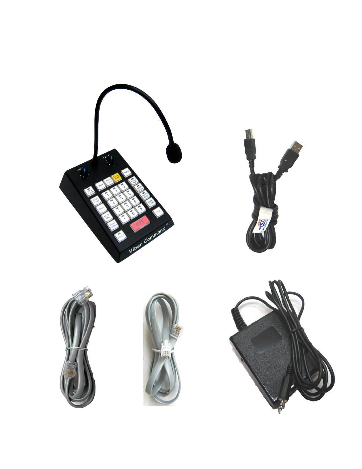
Parts List
The VCC-28 (Figure A).comes equipped with a USB “A/B” 2.0 cable (Figure B), a four wire RJ-9
satin cord (
replace the PJ-7 connecting cord included with dispatch headsets (Figure D). An optional foot
pedal is available (Figure E)
tab up – tab down
) (Figure C), and a six wire RJ-25 satin cord (
tab up – tab down
) to
Figure C Figure D Figure E
Figure A Figure B
VCC-28 Installation Guide with WAVE Page 4 of 33 Essential Trading Systems Corp.
Page 5

VCC-28 Key Pad
The VCC-28 key pad (see Figure F page 6) has five hardware keys that control certain functions of
the key pad. These keys are illuminated when they are active.
A
Key Latch: Changes the number keys (1 thru #) from momentary into latching action. When the
Key Latch key is illuminated (latched), the number key chosen (illuminated) will stay latched
“ready”. When the operator initiates PTT from the VCC-28 keypad, headset adapter, footswitch, or
software, the chosen channel will transmit. The same channel will stay ready until that key is
pushed again to unlatch it, another channel is chosen, or the Key Latch function is turned off. IE:
The operator wants channel 5 to stay ready for an extended period. He/She pushes the Key Latch
key (which illuminates), then selects the 5 key (which illuminates). The operator can now use the
PTT function from the VCC-28 keypad, headset adapter, footswitch, or software as needed to talk
on channel 5. When he/she is done with channel 5, another channel can be chosen and latched
ready, or the Key Latch key can be pushed and all keys will revert to momentary action.
B
Head Set: Enables –or- disables the wireless headset. When this key is illuminated (latched), all
available audio input is routed to the headset. When the Head Set key is not illuminated, the VCC28 routes the USB audio to the external speakers, and the incoming phone audio to the phone
handset. The headset PTT function is activated only when the Head Set key is illuminated
(latched).
C
Num Lock: Toggles the number keys (1 thru #) between numerical –or- programmed hot key.
This key works the same as a traditional keyboard Num Lock key. When it is illuminated (latched),
a number key acts like a numerical key and does not produce any programmed hot key sequence.
When it is not illuminated, a number key will produce the programmed hot key sequence
associated with it.
*
Num Lock overrides Key Latch* IE: The operator has Key Latch illuminated (latched) and is PTT
on channel 5. If he/she pushes Num Lock, channel 5 is disconnected and no longer active as a
transmit channel.
D
Phone Only: This key is only functional when the Phone key is illuminated (latched) and external
phone calls are being routed to the wireless headset. The Phone Only key toggles between phone
audio only –or- phone audio summed with USB audio getting through to the wireless headset. ALL
transmitting is disabled when Phone Only is illuminated (latched).
E
Phone: Determines how external phone calls will be routed. When this key is illuminated
(latched), the telephone handset is bypassed and the phone call is routed directly to the wireless
headset. The operator would pick up the handset to answer a call, set it aside, and use the
headset to speak into and listen from. When the call is completed, the operator would put the
handset back on the telephone cradle. This is necessary because the head set does not have the
ability to physically pick up or hang up a phone call. When the Phone key is not illuminated, the
phone handset works as a traditional handset (operator speaks into and listens from the handset)
and the Phone Only key is N/A.
For clarification of USB / PHONE audio paths and PTT Functional path, please see
Flowcharts 1, 2 , 3, 4 on pages 7 , 8, 9. 10.
VCC-28 Installation Guide with WAVE Page 5 of 33 Essential Trading Systems Corp.
Page 6
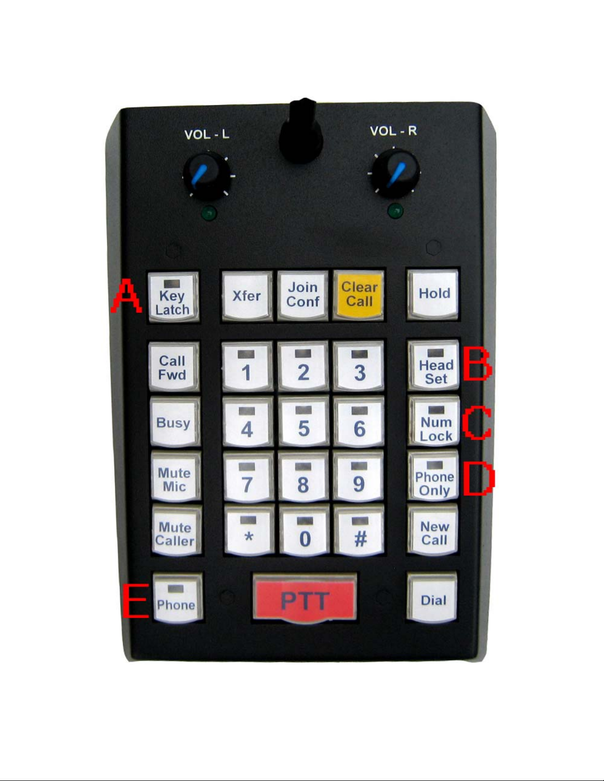
Figure F
VCC-28 Installation Guide with WAVE Page 6 of 33 Essential Trading Systems Corp.
Page 7
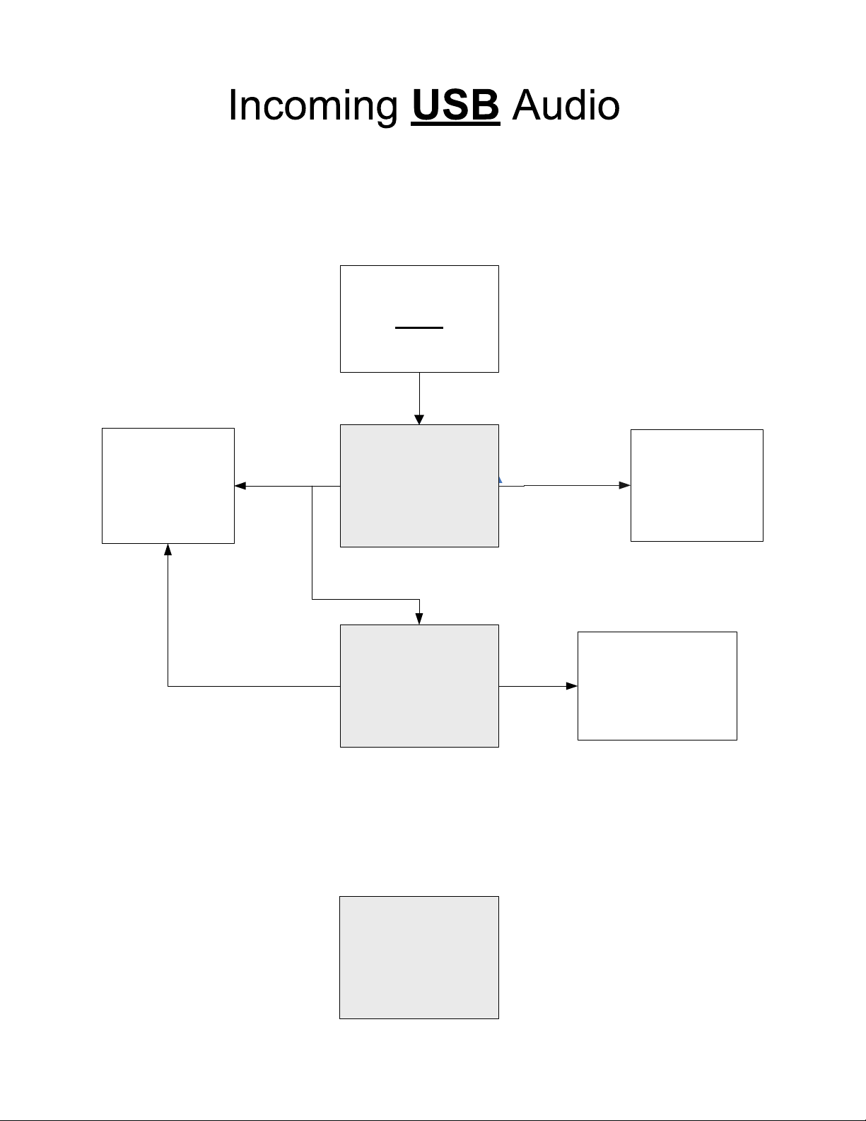
HEAD SET, PHONE ONLY, PHONE
incoming
USB
audio
Wireless
headset
ON OFF
HEAD SET
key
OFF
PHONE ONLY
ON
key
N/A
The PHONE key does not
have any bearing on the
incoming USB audio
External
speakers
Mutes incoming
USB Audio to
wireless headset
PHONE
key
Page 8
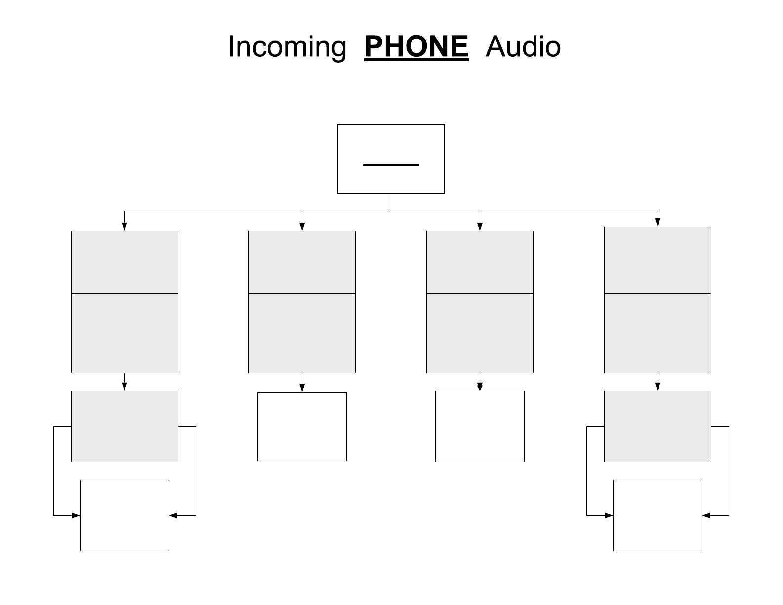
HEAD SET, PHONE, PHONE ONLY
incoming
PHONE
audio
HEAD SET
Key
ON
PHONE
Key
ON
ON OFF OFFON
PHONE ONLY
Key
Wireless
headset
HEAD SET
Key
OFF
PHONE
Key
OFF
Phone
handset
HEAD SET
Key
ON
PHONE
Key
OFF
Phone
handset
HEAD SET
Key
OFF
PHONE
Key
ON
PHONE ONLY
Key
Wireless
headset
Page 9
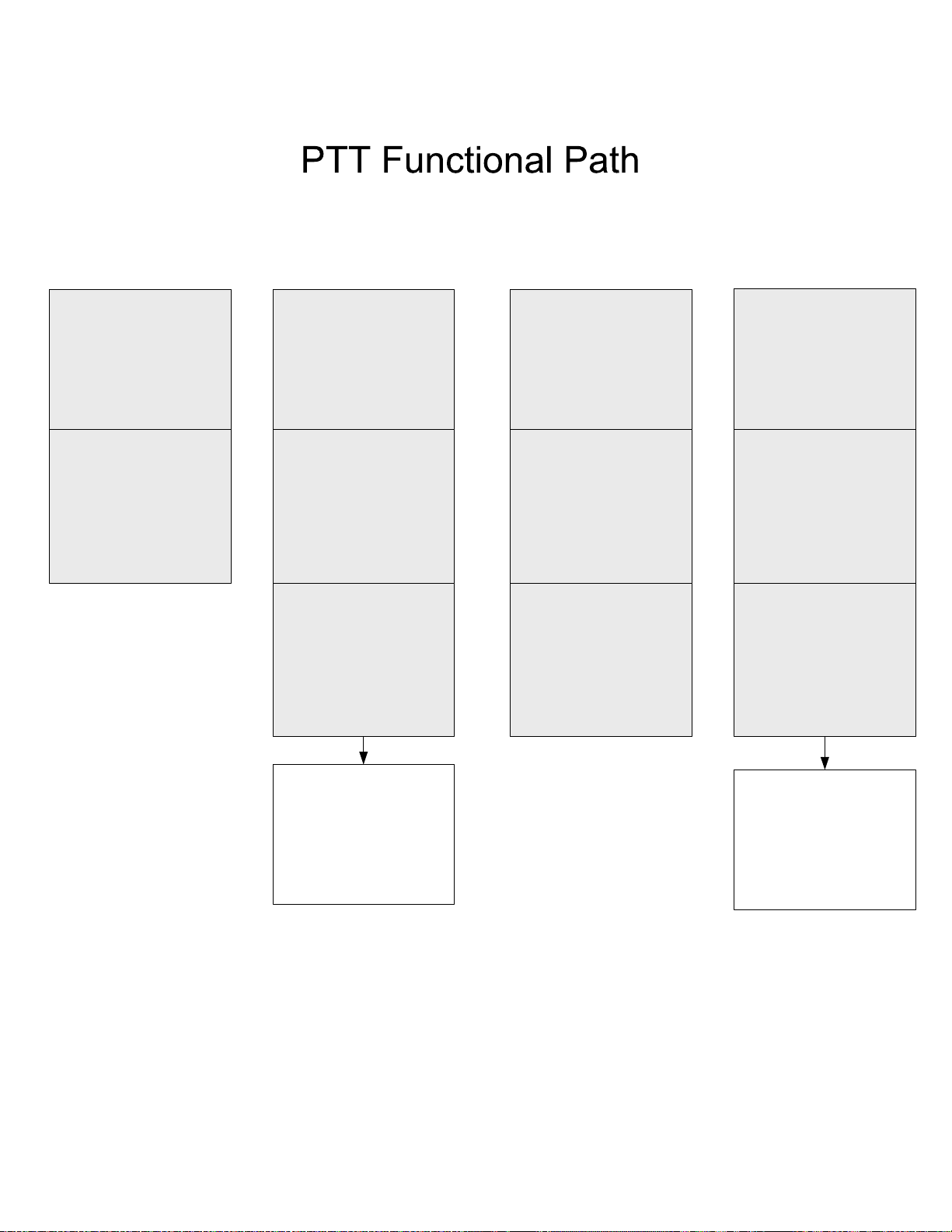
PTT Key ON
or
Foot Pedal
pressed
PTT Key ON
or
Foot Pedal
pressed
PTT Key ON
or
Foot Pedal
pressed
Head Set
Key
ON
Key Latch
Key
OFF
N/A
The PTT key does
not function
unless Key Latch
key is active AND
a channel has
been chosen on
the keypad
Key Latch
Key
ON
“3” Key
ON
Transmits audio
on Channel 3
Key Latch
Key
ON
Num Lock
Key
ON
N/A
The Num
Lock key
overrides the
Key Latch and
PTT keys
Key Latch
Key
ON
“3” Key
ON
Enables PTT
function from
wireless head set
Page 10
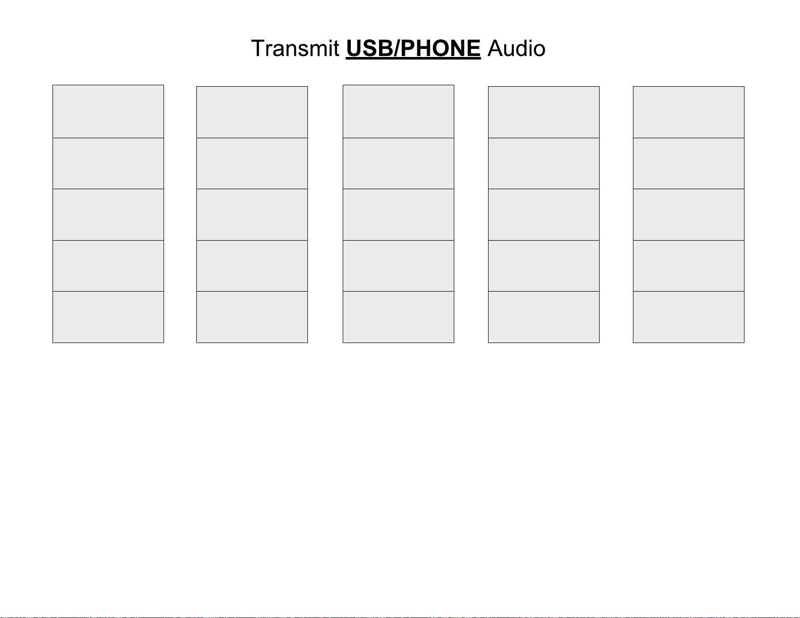
Key Latch
Key Latch
Key Latch
Key Latch
Key Latch
ON
Head Set
ON
“3” Key
ON
Phone
ON
Phone Only
ON
NO USB
TRANSMIT
Talk on
phone only
from the
headset
ON
Head Set
ON
“3” Key
ON
Phone
ON
Phone Only
OFF
USB TRANSMIT
from
PTT
FOOTPEDAL
HEADSET
Talk on phone and
USB together at
same time from
headset
ON
Head Set
ON
“3” Key
ON
Phone
OFF
Phone Only
OFF
USB TRANSMIT
from
PTT
FOOTPEDAL
HEADSET
Talk on USB
from headset
Talk on phone
from handset
ON
Head Set
OFF
“3” Key
ON
Phone
OFF
Phone Only
OFF
USB TRANSMIT
from
PTT
FOOTPEDAL
Talk on USB
from VCC-28
microphone
Talk on phone
from handset
OFF
Head Set
OFF
“3” Key
ON
Phone
OFF
Phone Only
OFF
USB TRANSMIT
from
pushing “3” key
Talk on USB
from VCC-28
microphone
Talk on phone
from handset
Page 11

Num Lock mode Key Chart
The functionality of the VCC-28 keys in Num Lock mode (the Num Lock key is illuminated) is
shown in Table 1. The number keys (1 through #) function as a normal key pad.
Key Label Programming Function
1 1 1
2 2 2
3 3 3
4 4 4
5 5 5
6 6 6
7 7 7
8 8 8
9 9 9
0 0 0
*
# # Left Shift 3
Head Set
Num Lock
Phone Only
New Call Ctrl-Alt-Shift-x Dial/Answer a call
Dial Ctrl-Alt-Shift-w Initiates the dialing of a new call
PTT Ctrl-Alt-Shift-z INOP: Over-ridden by Num Lock function
Phone
Mute Caller Ctrl-Alt-Shift-u Mute Caller
Mute Mic. Ctrl-Alt-Shift-t Mute Microphone for call
Busy Ctrl-Alt-Shift-s Stop taking incoming calls
Call Fwd Ctrl-Alt-Shift-r Forward incoming calls
Key Latch
Xfer Ctrl-Alt-Shift-n Transfer a call
Join Conf Ctrl-Alt-Shift-o Add/Remove a call from conference
Clear Call Ctrl-Alt-Shift-p Release (hang up) phone
Hold Ctrl-Alt-Shift-q Place call on hold
Foot Pedal Ctrl-Alt-Shift-z INOP: Over-ridden by Num Lock function
Hardware Key
Hardware Key
Hardware Key
Hardware Key
Hardware Key
*
Numpad *
Toggles Head Set: Enable –or- Disable
Toggles Number (1 - #) Keys: Numerical –or-
Programmed Hot Key
Toggles Audio Input: USB audio disabled with phone
audio only routed to head set –or- USB audio summed
with phone audio routed to head set. Disables xmit.
Toggles Phone Audio Routing: Phone audio routed to
handset –or- phone audio routed to head set
INOP: Over-ridden by Num Lock function
Table 1
VCC-28 Installation Guide with WAVE Page 11 of 33 Essential Trading Systems Corp.
Page 12

Hot Key mode Key Chart
The functionality of the VCC-28 keys in Hot Key mode (the Num Lock key is not illuminated) is
shown in Table 2. The number keys (1 through #) function as user programmed hot keys.
Key Label Programming Function
1 Ctrl-Alt-Shift-a
2 Ctrl-Alt-Shift-b
3 Ctrl-Alt-Shift-c
4 Ctrl-Alt-Shift-d
5 Ctrl-Alt-Shift-e
6 Ctrl-Alt-Shift-f
7 Ctrl-Alt-Shift-g
8 Ctrl-Alt-Shift-h
9 Ctrl-Alt-Shift-i
*
0 Ctrl-Alt-Shift-k
# Ctrl-Alt-Shift-l
Head Set
Num Lock
Phone Only
New Call Ctrl-Alt-Shift-x Dial/Answer a call
Dial Ctrl-Alt-Shift-w Initiates the dialing of a new call
PTT Ctrl-Alt-Shift-z Press/Hold to talk over selected channel
Phone
Mute Caller Ctrl-Alt-Shift-u Mute Caller
Mute Mic. Ctrl-Alt-Shift-t Mute Microphone for call
Busy Ctrl-Alt-Shift-s Stop taking incoming calls
Call Fwd Ctrl-Alt-Shift-r Forward incoming calls
Key Latch
Xfer Ctrl-Alt-Shift-n Transfer a call
Join Conf Ctrl-Alt-Shift-o Add/Remove a call from conference
Clear Call Ctrl-Alt-Shift-p Release (hang up) phone
Hold Ctrl-Alt-Shift-q Place call on hold
Foot Pedal Ctrl-Alt-Shift-z Press/Hold to talk over selected channel
Ctrl-Alt-Shift-j
Hardware Key
Hardware Key
Hardware Key
Hardware Key
Hardware Key
These keys are user programmable while in WAVE
Dispatch Communicator. Programming preferences
are unique to a user’s sign-in and profile.
Toggles Head Set: Enable –or- Disable
Toggles Number (1 - #) Keys: Numerical –or-
Programmed Hot Key
Toggles Audio Input: USB audio disabled with phone
audio only routed to head set –or- USB audio summed
with phone audio routed to head set. Disables xmit.
Toggles Phone Audio Routing: Phone audio routed to
handset –or- phone audio routed to head set
Table 2
Latches number (1 - #) keys
VCC-28 Installation Guide with WAVE Page 12 of 33 Essential Trading Systems Corp.
Page 13

Hardware Connections
(see Figure G, page 13)
HANDSET
This allows you to answer calls from a traditional telephone, but have them routed through the
VCC-28 for recording purposes.
PHONE
supplies this cable and it is necessary to maintain proper polarity between the VCC-28 and
phone.**
HEADSET
cord. **ETC supplies this cable and it is necessary for connectivity between the VCC-28 and
wireless headset.** This cable replaces the PJ-7 coiled cable supplied with dispatch wireless
headsets.
SPKR
: External speakers plug into this jack.
FOOT PEDAL
command. The foot pedal will PTT on any channel while the Key Latch function is active.
REC. OUT
recording device. Depending on the
only –or- USB radio and VCC-28 microphone/head set audio (dispatcher’s voice) output.
USB
connecting the VCC-28 by USB cable, it will install automatically with Windows/Linux drivers when
you power on your computer. Please note that it takes the system time to recognize new hardware
has been hooked up, and that the VCC-28 should not be disconnected until the “New Hardware
Installed” message is displayed.
SEL :
(closest to FOOT PEDAL
REC. OUT
output are recorded.
PWR
: A USB cable is plugged into this jack to connect the VCC-28 to a computer. Upon properly
This switch controls which audio is sent to the REC. OUT jack. In the RIGHT position
: This lights when the sound card successfully connects to Windows.
: The original telephone coil cord is used to connect the Hand Set to this RJ-9 port.
: The cable connecting the VCC-28 to the Phone base is an RJ-9 satin cord. **ETC
: The cable connecting the VCC-28 to the Wireless Headset base is an RJ-25 satin
: An optional foot pedal plugs into this jack. The foot pedal acts as a PTT
: This jack puts out an Analog signal at Line Level. It will connect to an external
SEL
switch status, this jack records either USB radio output
jack) only USB radio output is recorded. In the LEFT position (closest to
jack) both USB radio and VCC-28 microphone/head set audio (dispatcher’s voice)
VCC-28 Installation Guide with WAVE Page 13 of 33 Essential Trading Systems Corp.
Page 14

Figure G
VCC-28 Installation Guide with WAVE Page 14 of 33 Essential Trading Systems Corp.
Page 15

Windows XP Audio Device Hardware Configuration
Click on SSoouunnddss,, SSppeeeecchh,, aanndd AAuuddiioo DDeevviicceess icon located in the CCoonnttrrooll PPaanneell (Figure 1).
Figure 1
Click on the SSoouunnddss aanndd AAuuddiioo DDeevviicceess icon (Figure 2). Check “PPllaaccee vvoolluummee iiccoonn iinn tthhee tt
box so you can access these settings quicker in the future if needed (Figure 3).
aasskkbbaar
r”
Figure 2 Figure 3
VCC-28 Installation Guide with WAVE Page 15 of 33 Essential Trading Systems Corp.
Page 16

To ensure proper VCC-28 microphone performance, sound card settings must be adjusted after
initial device installation (or sudden disconnect or power loss). Click on the AAddvvaanncceedd button in the
DDeevviiccee vvoolluumme
does NOT show a MMiiccrroopphhoonnee device you will need to activate it. From the OOppttiioonnss drop down
menu choose PPrroopp
e box (Figure 4). The ETC VCC-28 SSppeeaakkeerr mixer window will open. If your window
s (Figure 5)
eerrttiiees
Figure 4 Figure 5
In the PPrrooppeerrttiieess window check the MMiiccrroopphhoonnee box (Figure 6) then click the OOKK button (Figure 7).
Figure 6 Figure 7
VCC-28 Installation Guide with WAVE Page 16 of 33 Essential Trading Systems Corp.
Page 17

You will see a MMiiccrroopphhoonnee device for ETC VCC-28 in the SSppeeaakkeerr window. Using your cursor,
move the SSppeeaakkeerr (master) volume lever up to the recommended playback level shown (Figure 8)
Figure 8
The MMiiccrroopphhoonnee volume lever must be down all the way and the Microphone Mute box must
cchheecckkeedd ((FFiigguurree 99))
FFiigguurree 9
VCC-28 Installation Guide with WAVE Page 17 of 33 Essential Trading Systems Corp.
9
Page 18

ATTENTION:
The microphone Mute
box must be checked.
An unchecked Mute box
will cause echo on the
network and down-time
for troubleshooting your
installation.
The Recording volume for the VCC-28 can now be adjusted. From the OOppttiioonnss drop down menu
choose PPrrooppeerrttiieess (Figure 10).
Figure 10
VCC-28 Installation Guide with WAVE Page 18 of 33 Essential Trading Systems Corp.
Page 19

In the PPrrooppeerrttiieess window click on the RReeccoorrddiinngg circle (Figure 11). Click the OOKK button (Figure 12).
.
Figure 11 Figure 12
The WWaavvee IInn (recording level) window will appear. Adjust the volume to the recommended level
(Figure 13). Close out the WWaavvee IInn window (Figure 14), and any other windows left open, and your
VCC-28 is ready to be configured with WAVE Dispatch Communicator software.
Figure 13 Figure 14
NOTE: The VCC-28 utilizes standard Windows/Linux USB audio device drivers. If the unit is
disconnected the settings may revert to default levels. These levels should be checked upon
reconnection in the event the VCC-28 becomes suddenly disconnected or loses power.
VCC-28 Installation Guide with WAVE Page 19 of 33 Essential Trading Systems Corp.
Page 20

Windows 7 Audio Device Hardware Configuration
Click on the SSoouunnddss icon located in the CCoonnttrrooll PPaanneell (Figure 15).
Figure 15
In the SSoouunndd window, choose the PPllaayybbaacckk tab, select SSppeeaakkeerrss EETTCC VVCCCC--2288 DDeeffaauulltt DDeevviiccee,,
click the PPrrooppeerrttiieess button (Figure 16). In the SSppeeaakkeerrss PPrrooppeerrttiieess window, choose the LLeevveellss tab.
Adjust the SSppeeaakkeerrss level to 90, the MMiicc
(Figure 17).
roopphhoonnee level to 0 (zero), and MMUUTTEE tthhee MMiiccrroopphhoonnee
r
and
Figure 16 Figure 17
VCC-28 Installation Guide with WAVE Page 20 of 33 Essential Trading Systems Corp.
Page 21

ATTENTION:
The microphone speaker icon
must be in mute mode. An un-muted microphone
will cause echo on the network and down-time for
troubleshooting your installation.
Click the OOKK button to return to the SSoouunndd window (Figure 18). In the SSoouunndd window, choose the
RReeccoorrddiinng
(Figure 19).
g tab, select MMiiccrroopphhoonnee EETTCC VVCCCC--2288 DDeeffaauu
lltt DDeevviiccee,,
Figure 18 Figure 19
and click the PPrrooppeerrttiieess button
VCC-28 Installation Guide with WAVE Page 21 of 33 Essential Trading Systems Corp.
Page 22

In the MMiiccrroopphhoonnee PPrrooppeerrttiieess window, choose the LLeevveellss tab. Adjust the MMiiccrroopphhoonnee level to 80
(Figure 20). Click the OOKK button to return to the SSoouunndd window (Figure 21).
Figure 20 Figure 21
Close out the SSoouunndd window, and any other windows left open, and your VCC-28 is ready to be
configured with WAVE Dispatch Communicator software.
VCC-28 Installation Guide with WAVE Page 22 of 33 Essential Trading Systems Corp.
Page 23

WAVE Dispatch Communicator Configuration
NOTE: These instructions require the WAVE Management Server to be configured, running, and
on the same network as the VCC-28.
The VCC-28 is now ready to be software configured for WAVE. The WWAAVVEE DDiissppaattcchh
CCoommmmuunniiccaattoor
DDiissppaattcchh CCoommmmuunni
the correct PPaasssswwoorrdd::.. Click on the SSeerrvveerr:: drop down menu and choose the correct WAVE
Management Server URL or address, then click on the LLoogg IInn button (Figure 22).
r can be started by clicking on the WAVE icon. The first screen to appear in WWAAVVEE
iccaattoorr is your WWAAVVEE LLooggiinn screen. Type in the correct UUsseerr NNaammee:: then type in
Figure 22
The UUsseerr PPrrooffiilleess window will open. Choose the correct PPrrooffiillee then choose the correct ZZoonnee:: from
the drop down menu (Figure 23). Click the SSeelleecctt button to enter your choices (Figure 24).
Figure 23 Figure 24
VCC-28 Installation Guide with WAVE Page 23 of 33 Essential Trading Systems Corp.
Page 24

The WWAAVVEE DDiissppaattcchh CCoommmmuunniiccaattoorr window will open (Figure 25).
Figure 25
Click on FFiillee and choose SSeettttiinnggss from the drop down menu (Figure 26).
Figure 26
VCC-28 Installation Guide with WAVE Page 24 of 33 Essential Trading Systems Corp.
Page 25

The WWAAVVEE DDiissppaattcchh CCoommmmuunniiccaattoorr SSeettttiinnggss window will open. Click on the Devices button
(Figure 27) and make sure the SSttaannddaarrdd DDeevvii
Figure 27 Figure 28
The HHoottkkeeyyss programming window will open. Click the NNeeww button to begin programming a hotkey
(Figure 29). When the KKeeyy SSeeqquueennccee SSeelleeccttiioonn window opens, the KKeeyy sseeqquueennccee area will be
empty (Figure 30).
: settings are correct. Click on the HHoottkkeeyyss button.
cceess:
Figure 29 Figure 30
VCC-28 Installation Guide with WAVE Page 25 of 33 Essential Trading Systems Corp.
Page 26

Push the VCC-28 key you want to program (the 22 key in this example) and the factory hot key
combination will appear in the KKeeyy CCoommbbiinnaattiioonn area (Figure 31). Click the OOKK button and the
s window will open. Choose PPTTTT oonn CChhaannnneell from the
t
WWAAVVEE DDiissppaattcchh CCoommmmuunniiccaattoorr SSeet
n drop down menu (Figure 32).
AAccttiioon
ttiinnggs
Figure 31 Figure 32
Choose the desired CChhaannnneell (Hoot 2 in this example) from the drop down menu (Figure 33). Click
the AAppppllyy button to save the CChhaannnneell’s programming (Figure 34).
Figure 33 Figure 34
VCC-28 Installation Guide with WAVE Page 26 of 33 Essential Trading Systems Corp.
Page 27

When you have programmed ALL the channels as desired, click the OK button (Figure 35) to close
the SSeettttiinnggss window. The WWAAVVEE DDiissppaattcchh CCoommmmuunniiccaattoorr window will open (Figure 25 pg 17).
Figure 35
The WAVE literature provided by Twisted Pair Solutions will give you more detailed information.
VCC-28 Installation Guide with WAVE Page 27 of 33 Essential Trading Systems Corp.
Page 28

APPENDIX: Windows USB Audio Device Settings
Microsoft .NET Framework (Option)
Note: The following steps are highly recommended if the microphone will be unplugged on a
regular basis.
When a USB audio device is disconnected the volume levels usually revert back to the factory
default settings. For maximum ETC equipment operation, these levels need to be set and stay
constant. The provided ETC Utility (installed later in this guide) uses Microsoft’s .NET Framework
4 to achieve this. Microsoft's .NET Framework 4 is free and can be downloaded at
http://www.microsoft.com/NET/
ETC Driver Utility Installation (Option)
By a quirk of Windows, sound devices were never meant to be portable / removable. Some of
these drivers date back to Windows-95 era. Since there are no provisions for portability, when a
device is disconnected the volume levels usually revert back to what is programmed in the
hardware of the soundcard. With the ETC series of USB microphones and sound cards this can be
inconvenient.
ETC’s Driver Utility makes sure the volume settings remain constant. This is a service running in
Windows, not actually a driver in the strict sense. As the volume changes these values are written
to the Registry. When a microphone is removed and later re-plugged, the previous volume levels
are read out of the registry and set in the Windows mixer panel.
Insert the provided Utility disc and open the UUSSBB PPrroodduuccttss folder (Figure 42). In the UUSSBB PPrroodduuccttss
folder, click on the IIMMPPOORRTTAANNTT–– RREEAADD
message (Figure 43). Make sure you copy the CCOOPPYY TTOO YYOOUURR DDEESSKKTTOOPP zipped folder to your
local computer’s desktop (Figure 43A).
Figure 42 Figure 42A
Figure 43 Figure 43A
MMEE FFIIRRSSTT
icon (Figure 42A) and read the enclosed text
VCC-28 Installation Guide with WAVE Page 28 of 33 Essential Trading Systems Corp.
Page 29

Once you have copied (or moved) the CCOOPPYY TTOO YYOOUURR DDEESSKKTTOOPP folder, open it and click on the
IINNSSTTAALLLLEER
VVoolluummee CCoonnttrrool
R icon (Figure 44). The EETTCC VVoolluummee CCoonnttrrooll window will open. Click on the RRee
l circle (Figure 45).
ppaaiirr EETTCC
Figure 44 Figure 45
Click the FFiinniisshh button (Figure 46). When IInnssttaallllaattiioonn CCoommpplleettee is shown,, click the CClloossee button
(Figure 47).
Figure 46 Figure 47
VCC-28 Installation Guide with WAVE Page 29 of 33 Essential Trading Systems Corp.
Page 30

The actual Batch file must be started now. Click on the SSTTAARRTT icon (Figure 48). The
CC::\\WWIINNDDOOWWSS\\ssyysstteemm3322\\ccmmdd..eexxe
volume control service (Figure 48). When the process stops, close the window. To verify the
volume control service is running, check for the EETTCC icon in the system tray (the lower right corner
of the screen by the clock) (Figure 49).
Figure 48 Figure 48A Figure 49
e window will open and run through the process of activating the
USB Microphone Removal Procedure (Option)
By right clicking on the EETTCC icon in the system tray (Figure 49), the UUnnpplluugg MMiiccrroopphhoonnee dialog box
opens. Click on UUnnpplluugg MMiiccrroopphhoonnee (Figure 50). The Volume Control window will open. Click the
K button (Figure 51). A DDiissccoonn
OOK
(Figure 52).
Figure 50 Figure 51 Figure 52
The Disconnect Complete window will self close as soon as the process is successfully stopped.
The ETC Volume Control service will automatically restart the next time a microphone is plugged
in.
neecctt CCoommpplleettee message will appear in the VVoolluummee CCoonnttrrooll window
n
VCC-28 Installation Guide with WAVE Page 30 of 33 Essential Trading Systems Corp.
Page 31

Uninstall ETC Volume Control (Option)
Go to the CC::\\WWIINNDDOOWWSS\\ssyysstteemm3322\\ccmmdd..eexxee directory run “stop.bat” (see Figure 48 pg 20). This
stops and removes the service.
In the Windows Control Panel under “Add or Remove Programs” find ETC Volume Control and
click the RReemmoovvee button.(Figure 53).
Figure 53
Click the Yes button to remove the program (Figure 54)
Figure 54
VCC-28 Installation Guide with WAVE Page 31 of 33 Essential Trading Systems Corp.
Page 32

Specifications
Weight: 2.75 lbs
Dimensions: 8.25”L x 6.25”W x 2”H (chassis only)
Frequency Response: 200 Hz – 8 KHz @ -3db
Distortion: .05% at max output
USB Powered
RJ-9 Four wire (stranded) Satin Cord Pin Out
(known as
Pin 1 Black Pin 1 Black
Pin 2 Red Pin 2 Red
Pin 3 Green Pin 3 Green
Pin 4 Yellow Pin 4 Yellow
tab up – tab down
)
RJ-25 Six wire (stranded) Satin Cord Pin Out
(known as
Pin 1 Blue Pin 1 Blue
Pin 2 Yellow Pin 2 Yellow
Pin 3 Green Pin 3 Green
Pin 4 Red Pin 4 Red
Pin 5 Black Pin 5 Black
Pin 6 White Pin 6 White
tab up - tab down
)
NOTE: The gain settings on the Plantronics CA12CD base need to be set at:
• Microphone Volume = 2
• Head Set Volume = 4
(switches are on the bottom of the base)
Endorsement of ETC or ETC’s products is not implied by use of other companies’ product names.
To ensure highest quality, ETC reserves the right to change product specifications at any time.
Windows® is a registered trademark of Microsoft Corporation in the United States & other countries
Linux® is a registered trademark of Linus Torvalds
WAVE® is a registered trademark of Twisted Pair Solutions
Plantronics® is a registered trademark of Plantronics, Inc.
VCC-28 Installation Guide with WAVE Page 32 of 33 Essential Trading Systems Corp.
Page 33

VCC-28 Hardware Product Limited Warranty
ETC warrants that your ETC hardware product shall be free from defects in material and workmanship for
the length of time specified in the Warranty Periods below, beginning from the date of purchase. Except
where prohibited by applicable law, this warranty is nontransferable and is limited to the original purchaser.
This warranty gives you specific legal rights, and you may also have other rights that vary under local laws
Remedies
ETC’s entire liability and your exclusive remedy for any breach of warranty shall be, at ETC’s option, (1) to
repair or replace the hardware, or (2) to refund the price paid, provided that the hardware is returned to the
point of purchase or such other place as ETC may direct with a copy of the sales receipt or dated itemized
receipt. Shipping and handling charges may apply except where prohibited by applicable law. ETC may, at
its option, use new or refurbished or used parts in good working condition to repair or replace any hardware
product. Any replacement hardware product will be warranted for the remainder of the original warranty
period or thirty (30) days, whichever is longer or for any additional period of time that may be applicable in
your jurisdiction. This warranty does not cover problems or damage resulting from (1) accident, abuse,
misapplication, or any unauthorized repair, modification or disassembly; (2) improper operation or
maintenance, usage not in accordance with product instructions or connection to improper voltage supply;
or (3) use of consumables, such as replacement batteries, not supplied by ETC except where such
restriction is prohibited by applicable law.
How to Obtain Warranty Support
Before submitting a warranty claim, we recommend you contact ETC support at support@essentialtel.com
for technical assistance. Valid warranty claims are generally processed through the point of purchase
during the first thirty (30) days after purchase; however, this period of time may vary depending on where
you purchased your product – please check with ETC for details. Warranty claims or other product related
questions should be addressed directly to ETC. at support@essentialtel.com
between the hours of 8:30 AM and 5:00 PM.
Limitation of Liability
ETC SHALL NOT BE LIABLE FOR ANY SPECIAL, INDIRECT, INCIDENTAL OR CONSEQUENTIAL
DAMAGES WHATSOEVER, INCLUDING BUT NOT LIMITED TO LOSS OF PROFITS, REVENUE OR
DATA (WHETHER DIRECT OR INDIRECT) OR COMMERCIAL LOSS FOR BREACH OF ANY EXPRESS
OR IMPLIED WARRANTY ON YOUR PRODUCT EVEN IF ETC HAS BEEN ADVISED OF THE
POSSIBILITY OF SUCH DAMAGES. Some jurisdictions do not allow the exclusion or limitation of special,
indirect, incidental or consequential damages, so the above limitation or exclusion may not apply to you.
©
Essential Trading Systems Corps. All intellectual property rights in this publication are owned by Essential
Trading Systems Corps. and are protected by United States copyright laws, other applicable copyright laws
and international treaty provisions. Essential Trading Systems Corps. Retains all rights not expressly
granted. No part of this publication may be reproduced in any form whatsoever or used to make any
derivative work without prior written approval by Essential Trading Systems Corps. No representation of
warranties for fitness for any purpose other than what is specifically mentioned in this guide is made either
by Essential Trading Systems Corps. or its agents. Essential Trading Systems Corp. reserves the right to
revise this publication and make changes without obligation to notify any person of such revisions or
changes. Essential Trading Systems Corps. may make improvements or changes in the product(s) and/or
the program(s) described in this documentation at any time. All rights reserved.
or call (860) 295-8100 option 3
VCC-28 Installation Guide with WAVE Page 33 of 33 Essential Trading Systems Corp.
 Loading...