

Page 1

Touchscreen
User Manual
Revision B
Copyright © 2010 Electronic Theatre Controls, Inc.
All Rights reserved.
Product information and specifications subject to change.
Part Number:
7184M1200
Released: 2010-07
Rev B
Page 2

Table of Contents
Introduction . . . . . . . . . . . . . . . . . . . . . . . . . .1
Touchscreen Specifications . . . . . . . . . . . . . . . . . . . . . . . . . . . . . . . .1
Warnings and Notice Conventions . . . . . . . . . . . . . . . . . . . . . . .2
Contacting ETC . . . . . . . . . . . . . . . . . . . . . . . . . . . . . . . . . . . . . .2
Overview. . . . . . . . . . . . . . . . . . . . . . . . . . . .3
Power and Data Connections . . . . . . . . . . . . . . . . . . . . . . . . . . . . . .3
LinkConnect. . . . . . . . . . . . . . . . . . . . . . . . . . . . . . . . . . . . . . . . .3
NetConnect . . . . . . . . . . . . . . . . . . . . . . . . . . . . . . . . . . . . . . . . .3
Touchscreen Inputs, Outputs and Indicators . . . . . . . . . . . . . . . . . . .4
Ports . . . . . . . . . . . . . . . . . . . . . . . . . . . . . . .
Buttons and Indicator LEDs . . . . . . . . . . . . . . . . . . . . . . . . . . . . .4
Status . . . . . . . . . . . . . . . . . . . . . . . . . . . . . . . . . . . . . . . . . . . . . . .5
LON . . . . . . . . . . . . . . . . . . . . . . . . . . . . . . . . . . . . . . . . . . . . . . . . .5
NET . . . . . . . . . . . . . . . . . . . . . . . . . . . . . . . . . . . . . . . . . . . . . . . . .5
ControlDesigner Software . . . . . . . . . . . . . . . . . . . . . . . . . . . . . . . . .5
Image Resources. . . . . . . . . . . . . . . . . . . . . . . . . . . . . . . . . . . . .5
Image Format . . . . . . . . . . . . . . . . . . . . . .
Sound Resources . . . . . . . . . . . . . . . . . . . . . . . . . . . . . . . . . . . .6
Sound File Format . . . . . . . . . . . . . . . . . . . . . . . . . . . . . . . . . . . . .6
. . . . . . . . . . . . . . .4
. . . . . . . . . . . . . . . . . . .6
Touchscreen Setup Menu. . . . . . . . . . . . . . . 7
Setup Menu . . . . . . . . . . . . . . . . . . . . . . . . . . . . . . . . . . . . . . . . . . . .8
About tab . . . . . . . . . . . . . . . . . . . . . . . . . . . . . . . . . . . . . . . . . . .8
Screen tab . . . . . . . . . . . . . . . . . . . . . . . . . . . . . . . . . . . . . . . . . .9
Calibrate Touchscreen . . . . . . . . . . . . . . . . . . . . . . . . . . . . . . . . .10
Sound tab . . .
Comms tab . . . . . . . . . . . . . . . . . . . . . . . . . . . . . . . . . . . . . . . .11
Config tab . . . . . . . . . . . . . . . . . . . . . . . . . . . . . . . . . . . . . . . . .12
Protected Features and Tabs. . . . . . . . . . . . . . . . . . . . . . . . . . . . . .13
Timed Events. . . . . . . . . . . . . . . . . . . . . . . . . . . . . . . . . . . . . . .13
Add Event . . . . . . . . . . . . . . . . . . . . . . . . . . . . . . . . . . . . . . . . . . .14
Files tab . . . . . . . . . . . . . . . . . . . . . . . . . . . . . . . . . . . . . . . . . .17
Saving and Loading Configuratio
Network tab . . . . . . . . . . . . . . . . . . . . . . . . . . . . . . . . . . . . . . . .18
IP Addressing . . . . . . . . . . . . . . . . . . . . . . . . . . . . . . . . . . . . . . . .19
System tab. . . . . . . . . . . . . . . . . . . . . . . . . . . . . . . . . . . . . . . . .19
Reload Firmware . . . . . . . . . . . . . . . . . . . . . . . . . . . . . . . . . . . . . .20
Reset to Defaults . . . . . . . . . . . . . . . . . . . . . . . . . . . . . . . . . . . . .20
. . . . . . . . . . . . . . . . . . . . . . . . . . . . . . . . . . . . . .11
n Files . . . . . . . . . . . . . . . . . . . .18
Cleaning the Display. . . . . . . . . . . . . . . . . . 21
ETC®, Un ison® a nd Para dig m ™ are e ither re gi st ered t ra de mar ks or trade ma rks o f E lect roni c T heat re Co nt rols , I nc.
in t he Unite d Stat es and oth er coun tr ies. All oth er tradema rks, bot h mark ed and not marked, are the pro pe rty of the ir
res pe ct ive owne rs . ETC i nt en ds th is docume nt, whether pr inte d o r el ectroni c, to b e pr ovid ed i n its e nt irety.
i
Page 3
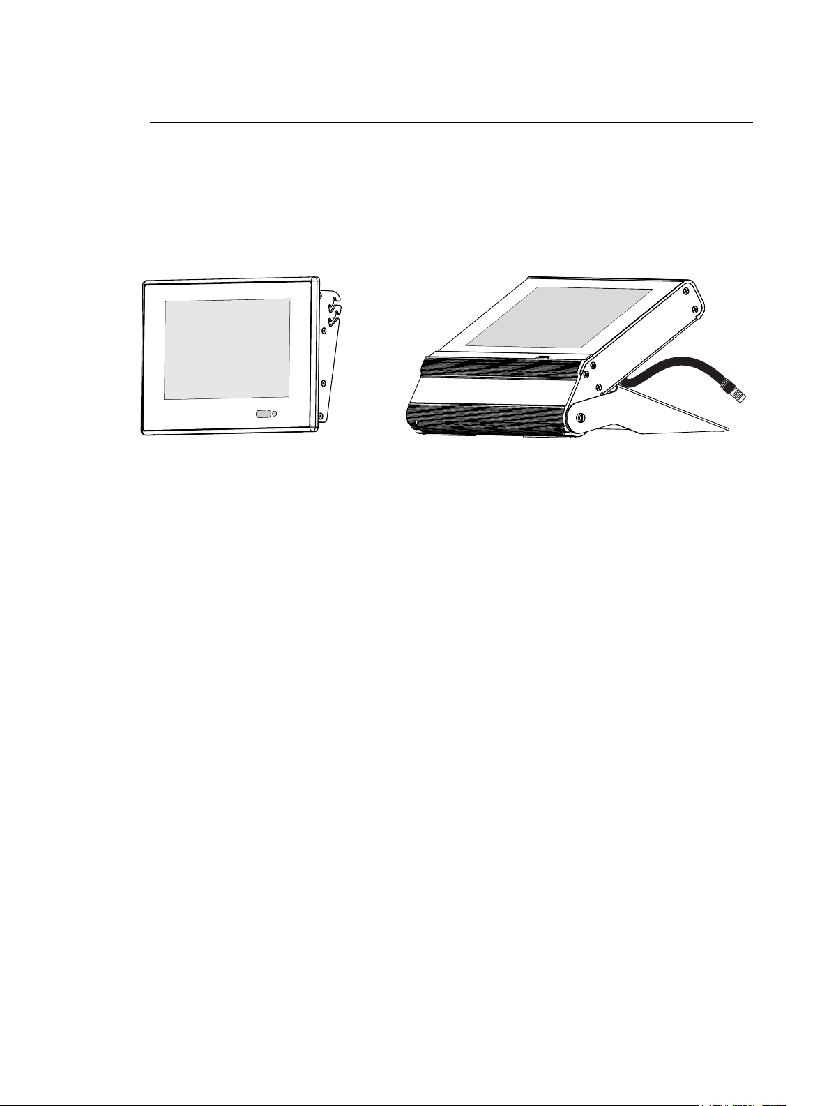
Introduction
Unison Paradigm Wall Mount Touchscreen Unison Paradigm Portable Touchscreen
Welcome to the Paradigm Touchscreen user’s guide. This manual contains the procedures
for setup of the Paradigm Touchscreens including theme file loading, menu navigation,
touchscreen calibration, timed events editing, and cleaning instructions.
Reference the related Paradigm Touchscreen Installation or Setup Guide for information on
installation and hardware setup.
The wall mount Touchscreen is also available with a locking cover or in a rack mount panel.
Touchscreen Specifications
The Paradigm Touchscreen is a high resolution color Touchscreen for use with the
Paradigm Architectural Control Processor (P-ACP). The Touchscreen features a 7"
(17.8cm) WVGA display with 800x480 pixel resolution utilizing 24-bit color depth and a 10:6
aspect ratio.
Introduction 1
Page 4
Warnings and Notice Conventions
These symbols are used in ETC documentation to alert you to danger or important
information:
Note:
CAUTION:
Notes are helpful hints and information that is supplemental to the main text.
A Caution statement indicates situations where there may be undefined or
unwanted consequences of an action, potential for data loss or an equipment
problem.
WARNING:
A Warning statement indicates situations where damage may occur, people
may be harmed, or there are serious or dangerous consequences of an
action.
WARNING:
RISK OF ELECTRIC SHOCK! This warning statement indicates situations
where there is a risk of electric shock.
Contacting ETC
If you are having difficulties with your Paradigm Touchscreen, your most convenient
resources are the references given in this user guide. To search more widely, try the ETC
website at www.etcconnect.com
Technical Services directly at one of the offices identified below. Emergency service is
available from all ETC offices outside of normal business hours. When calling for help,
please have the following information handy:
• Your location and job name.
. If none of these resources is sufficient, contact ETC
• A complete list of ETC product including model and serial numbers if available.
• A list of other installed components in your system (Unison
®
, other consoles, etc.).
Americas United Kingdom
Electronic Theatre Controls Inc. Electronic Theatre Controls Ltd.
Technical Services Department Technical Services Department
3031 Pleasant View Road 26-28 Victoria Industrial Estate
Middleton, WI 53562 Victoria Road,
800-775-4382 (USA, toll-free) London W3 6UU England
+1-608 831-4116 +44 (0)20 8896 1000
service@etcconnect.com service@etceurope.com
Asia Germany
Electronic Theatre Controls Asia, Ltd. Electronic Theatre Controls GmbH
Technical Services Department Technical Services Department
Room 1801, 18/F Ohmstrasse 3
Tower 1, Phase 1 Enterprise Square 83607 Holzkirchen, Germany
9 Sheung Yuet Road +49 (80 24) 47 00-0
Kowloon Bay, Kowloon, Hong Kong techserv-hoki@etcconnect.com
+852 2799 1220
service@etcasia.com
Please email comments about this manual to: TechComm@etcconnect.com
2 Unison Paradigm Touchscreen User Manual
Page 5

Overview
Power and Data Connections
Paradigm Wall Mount and Rack Mount Touchscreen stations are designed to connect to
the Paradigm Control system using either LinkConnect or NetConnect for power and data.
Note:
A Paradigm Portable Touchscreen is designed to connect to the Paradigm Control system
using only Portable LinkConnect; a Unison Heritage Portable Connector (UH1RS) station
wired using LinkConnect is required.
LinkConnect
LinkConnect uses Echelon® LonTalk® with LinkPower to connect between the Paradigm
Touchscreen and the Paradigm Architectural Control Processor.
The Paradigm Wall Mount Touchscreen, when connected over LinkConnect, utilizes three
watts of power at 24 Vdc.
Reference the related Touchscreen installation guide for details of installation and setup.
NetConnect
NetConnect uses Power over Ethernet (PoE 802.3af) communications to connect between
the Paradigm Touchscreen and the host Paradigm rack enclosure.
Reference the related Touchscreen installation guide for details of installation, wiring
requirements and setup.
The ground connection to the Wall Mount and Rack Mount Touchscreen is
provided through the RJ11 connection, regardless of the data connection type,
LinkConnect or NetConnect.
Overview 3
Page 6
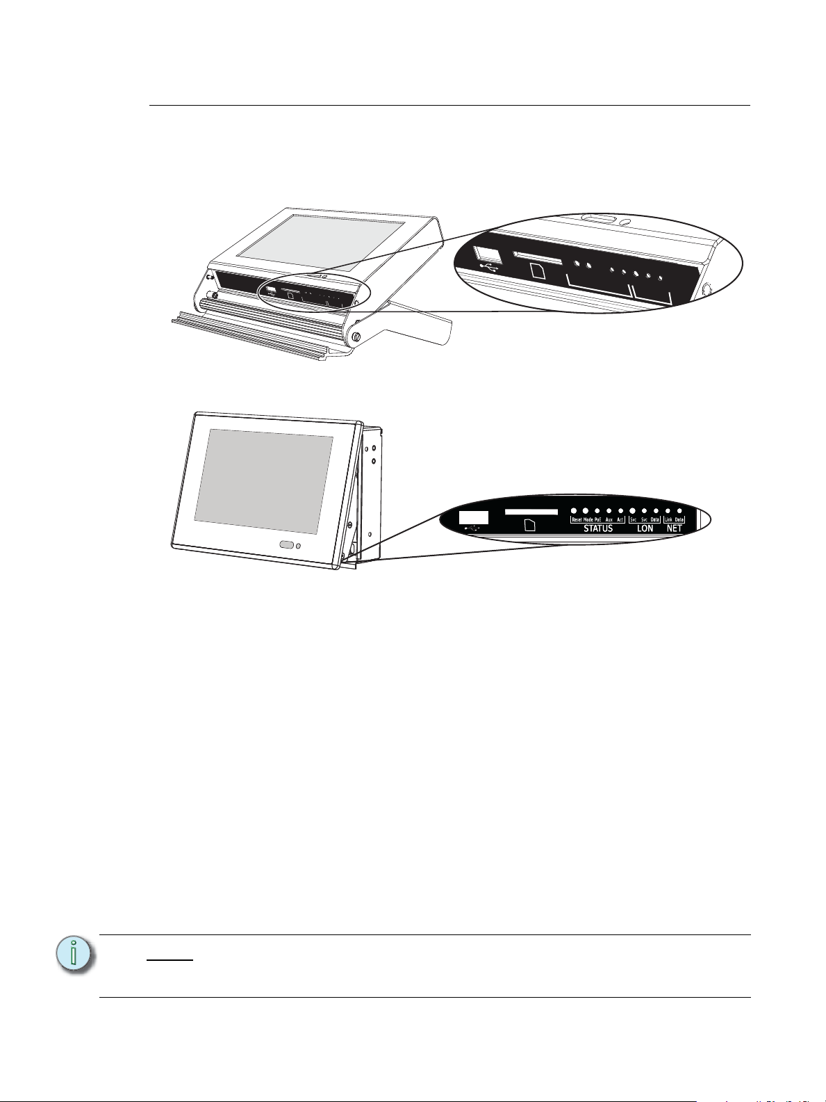
Touchscreen Inputs, Outputs and Indicators
Reset
Mode
Aux
Act
Svc
Svc
Data
LON
Status
To change the Touchscreen into a service
position, lift up and pull out to a slight angle
from the bottom of the display. The I/O panel
is located on the bottom side.
Each model of the Touchscreen has an I/O panel that includes an USB port, SD card slot,
and a selection of indicators and service pins. The indicator and service pin selections vary
depending on the model of Touchscreen.
The Portable Touchscreen I/O panel is revealed behind a door on the bottom of the unit.
Reset
Mode
Aux
Act
Svc
Status
Svc
Data
LON
The Wall Mount and Rack Mount Touchscreen I/O panel is located on the bottom side of
the unit, viewable only when the LCD is in the Service position.
Ports
• USB port - This connection is used for local upload or download of configuration and
theme files. The USB connection supports all USB keys that require 250mA of power
or less.
• Secure Digital (SD) card slot - This connection is used for local upload and download
of configuration and theme files. The SD card slot supports standard SD cards up to
2GB. High capacity (SDHC) cards are not supported.
Buttons and Indicator LEDs
Each of the buttons and indicators on the Touchscreen I/O panel are labeled and grouped
according to its relationship and function.
For example, the section labeled with “Status” include all buttons and indicators that relate
specifically to the Touchscreens function and features including software reset, setup menu
access, and power source.
Buttons and indicators that relate specifically to LinkConnect data use are labeled in the
“LON” section and others that relate specifically to NetConnect data use are labeled in the
“NET” section.
Note:
Availability of buttons and indicators varies according to the Touchscreen model.
For example, a Paradigm Portable Touchscreen will not have a “NET” related
items as it does not support NetConnect.
4 Unison Paradigm Touchscreen User Manual
Page 7

Status
• “Reset” button - when pressed, resets the LCD software causing a reboot and service
pin message to the connected processor.
• “Mode” button - press once for “Setup menu”. Press and hold four seconds to
calibrate the Touchscreen.
• “PoE” LED- illuminates solid when Power over Ethernet is present (NetConnect only).
• “Aux” LED - illuminates solid when the Touchscreen is powered (LinkConnect only).
• “Act” LED - reserved for future development.
LON
• “Svc” pin button - sends a “service pin” message when pressed, which sends the
station Neuron ID to the connected processor. This provides the same function as the
on screen [Service Pin] button found in the Setup Menu.
• “Svc” LED - illuminates when a service pin command has been sent to the processor.
• “Data” LED - illuminates (flashing) to indicate transmission of data packets when the
Touchscreen is connected to a processor using LinkConnect.
NET
• “Link” LED - indicates a valid network connection is present to the Touchscreen using
NetConnect. This indicates connection to any Ethernet device (such as a switch).
• “Data” LED - indicates by flashing LED when data is transmitted over NetConnect.
This indicates connection to any network device (such as a switch).
ControlDesigner Software
Paradigm ControlDesigner software is used to create graphical layouts and page
navigation for Unison Paradigm Touchscreen stations. These graphical layouts and page
navigations are also known as the Touchscreen configuration file.
Among the many other tools provided in ControlDesigner software, a user is provided the
ability to add custom images to Touchscreen controls such as page backgrounds and
button states.
The Paradigm Touchscreen supports configuration files that are uploaded from the
connected Paradigm Architectural Control Processor (P-ACP) or loaded directly to the
Touchscreen using removable media, such as a USB key or Secure Digital (SD) card.
Image Resources
Multiple unique page background images can be used in a single Paradigm Touchscreen
configuration. To reduce the configuration file size and amount of data the Touchscreen
must process, all background images should be resized to the native resolution of the
Touchscreen, 800 x 480 pixels, or smaller.
Other control object states may also have unique images. Image resources should be sized
as small as possible for the application they are to be used.
Note:
Overview 5
For best results, an image that is used more than one time in a Touchscreen
configuration should be added to the theme using Paradigm ThemeDesigner
software. Adding the image to the theme reduces the configuration file size,
thereby reducing the file transfer time and storage space required on the
Touchscreen. Contact ETC Technical Services for assistance.
Page 8

Image Format
ControlDesigner software supports the following image formats for use on page
backgrounds and button states:
• Portable Network Graphic (.png).
• Graphical Interchange Format (.gif).
• JPEG Image File (.jpg). Excluding compressed .jpg files as they will not display on the
Paradigm Touchscreen.
• X11 Pixmap Graphic (.xpm)
Note:
ETC recommends that all images used in a configuration file for the Paradigm
Touchscreen be a .png file format as it supports transparency, reduces the file
size, and maintains the best performance of the Touchscreen.
Configuration files and even specific image resources that are too large will not
load onto the Touchscreen.
Sound Resources
Paradigm Portable Touchscreen stations are equipped with an integrated speaker; a
standard hardware feature. In ControlDesigner software, sounds (audio) can be associated
to a control’s skin as to provide audible feedback, as indication of a control’s state change.
Sound File Format
The Paradigm Touchscreen station uses Waveform Audio File Format (.wav) for audio
playback. Support is provided for either 8-bit or 16-bit stereo formatted .wav files with a
sample rate of 8 kHz, 11 kHz, 22kHz, or 44kHz.
6 Unison Paradigm Touchscreen User Manual
Page 9

Touchscreen Setup Menu
How a Touchscreen behaves when it is powered depends on two things:
1 Is a ControlDesigner configuration file loaded onto the Touchscreen?
2 Is the Touchscreen bound/connected with the P-ACP?
When both of these are true, and the Touchscreen is powered, the configuration will load
to the home page of the selected configuration.
On initial power-up, with no ControlDesigner configuration installed or when the
Touchscreen is not bound/connected to a processor, the Touchscreen displays the default
splash page; which includes the ETC logo and two buttons; [Setup] and [Service Pin].
Pressing the [Setup] button accesses the Setup Menu where setup options and technical
information are displayed. Pressing the [Service Pin] button issues a binding request to
the Paradigm Architectural Control Processor over the control network. When the
Touchscreen is bound/connected to a processor, a configuration file will begin to load.
Touchscreen Setup Menu 7
Page 10

Setup Menu
Pressing the [Setup] button on the default page displays the About tab of the Touchscreen
setup menu. Alternatively, you can access the setup menu by pressing the “Mode” pin on
the Touchscreen I/O panel. See “Touchscreen Inputs, Outputs and Indicators” on page 4.
Each tab of the setup menu displays a footer of buttons including [Service Pin], [Ok] and
[Cancel].
About tab
Note:
The About tab displays read-only information pertaining to the Touchscreen including;
• MAC Address: a unique identifier assigned to the Touchscreen by ETC for
identification over the Paradigm network.
• IP Address: the current network IP address assigned to the Touchscreen. This number
can be modified from the Network tab.
• Neuron Id: a station specific unique hardware address that is permanent to the
Touchscreen. This ID is used by the Paradigm Architectural Control Processor to bind/
associate (bind) stations within the LightDesigner configuration.
• Bootloader: the bootloader software version.
• Firmware: the firmware version loaded onto the Touchscreen. Firmware can be
updated, reference System tab, page 19 for instructions.
The firmware version in the Touchscreen must be compatible with the firmware
version in the Paradigm Architectural Control Processor (P-ACP) for the two
devices to communicate.
• Memory Usage: a Paradigm Touchscreen has 128 megabytes (Mb) of memory
available for configuration storage. The “Memory Usage” section displays the “Total”
memory available, the memory “Used” and the available memory that is “Free” for use.
• Boot Reason: the last action that caused the Touchscreen to boot. Reasons for reboot
could be due to a [Reset] button press on the Touchscreen I/O panel, power loss, etc.
8 Unison Paradigm Touchscreen User Manual
Page 11

• Watchdog: displays the status of the Watchdog tool.
Note:
Screen tab
Watchdog is a service that monitors Touchscreen activity and will automatically
reboot the device in the event it would suffer a crash or lockup. Watchdog should
be “enabled” unless instructed otherwise by ETC Technical Services.
Note:
The “Screen” tab provides user settings for the Touchscreen including:
• Backlight Level: a level bar is provided to set the relative brightness of the
Touchscreen backlight. By default, the level is set to full.
When the light sensor is “On”, the backlight level sets the maximum level of
brightness.
• Backlight Timeout: sets the length of inactivity time before the backlight fades to its
backlight timeout level. This is separate from any configuration related Inactivity
Timeout settings.
• Backlight Timeout “Level”: the intensity level the backlight will fade to when its
“Backlight Timeout” has been reached. This level can be set to either “Off” or “Dim”.
• Light Sensor: allows the Touchscreen to determine an appropriate Backlight Level
based on ambient light in the space. The internal light sensor measures the ambient
light and adjusts the backlight proportionally based on the established backlight level
settings. By default, the light sensor is “Off”.
• Proximity Sensor: when enabled (“On” which is default), proximity allows the
Touchscreen to detect a user’s presence as he/she approaches the Touchscreen for
use. When proximity is detected, the Touchscreen automatically turns on the backlight
and displays the inactivity page that was configured in ControlDesigner. Proximity is
only supported on the Paradigm Wallmount Touchscreen.
• The proximity sensor uses active IR to determine proximity to the Touchscreen.
The sensor has a sensing distance of approximately one foot with a field angle of
15 degrees.
Touchscreen Setup Menu 9
Page 12

• If the sensor registers any moving or stationary objects within this range, it will
“wake” the station from its sleeping state and reset the backlight timeout and the
station inactivity timer as set in ControlDesigner.
Note:
Be aware of stationary objects (such as rack doors) that remain within the sensing
range as it may interfere with the function of the sensor. In these applications, it is
best practice to disable the Proximity Sensor.
The proximity sensor is looking for reflected IR; therefore any IR devices (such as
alarms or listening assistance systems) within a range of the proximity sensor may
prevent the system from sleeping or displaying an inactivity page.
Calibrate Touchscreen
The “Screen” tab provides a [Calibrate Touchscreen] button that will launch the
calibration display. This display is provided as a tool for recalibration of the Touchscreen.
Calibration may be required if presses on the Touchscreen are recognized in an area other
than where the screen was pressed.
Note:
To calibrate the Touchscreen, simply touch as close to the center of the “+” symbol as it is
displayed. The “+” symbol will move to five separate coordinates on the touchscreen to
complete the calibration.
Alternatively, press and hold the [Mode] button (located on the I/O panel of the
Touchscreen) for four seconds to launch the calibration display.
When all five coordinates have been calibrated, press [Close] to return to the previously
displayed page. If you are unsatisfied with the calibration results, press [Recalibrate] to
start the calibration again or press [Clear] to clear your settings.
10 Unison Paradigm Touchscreen User Manual
Page 13

Sound tab
The “Sound” tab provides a volume control for the master volume level of the
Touchscreen’s built-in speaker.
Comms tab
The “Comms” tab provides read-only information pertaining to which Paradigm
Architectural Control Processor (P-ACP) the Touchscreen is connected over the Paradigm
control network.
• Server Name: this is the name of the P-ACP
Touchscreen Setup Menu 11
Page 14

• Connection Type: this is the type of connection that is made to the P-ACP. Options
include “Ethernet” which is NetConnect, or “Lon” which is LinkConnect.
Note:
Config tab
This is a very useful tool when troubleshooting your communication connection
between the Paradigm Touchscreen and your Paradigm control system.
When a Paradigm Touchscreen is connected by NetConnect, the IP address of
the P-ACP will display as the “Server Address”.
A Paradigm Portable Touchscreen will indicate the Connector ID of the Portable
Connector Station (UH1RS) it is connected to.
The “Config” tab displays the project information that was provided in ControlDesigner.
Project information can only be modified in ControlDesigner.
12 Unison Paradigm Touchscreen User Manual
Page 15

Protected Features and Tabs
The “Files”, “Network” and “System” tabs as well as the “Timed Events” feature on the
“Config” tab are protected by passcode and should be used only by trained personnel.
Typically these displays are accessed only during system commissioning. Pressing any of
the tab names will display a keypad for passcode entry.
Note:
Enter your four digit passcode _ _ _ _ to access these menus. These protected
tabs should be accessed only by trained personnel.
Timed Events
The “Timed Events” button on the Config tab is a passcode protected feature that allows
users to add and edit Timed Events. Press the [Timed Events] button on the Config tab, and
enter the passcode to begin. All created timed events will display in the “Timed Event
Setup” menu. From this menu you can add new events, or delete or edit existing events in
the list.
Note:
ControlDesigner provides a page navigation action to reach a Timed Event
configuration directly. Use this feature to provide access for end users who wish
to edit Timed Events.
Touchscreen Setup Menu 13
Page 16

Adding a new event and editing an event are similar in process.
Add Event
Step 1: Press the [Add] button, a “New Timed Event” configurator will display.
Step 2: Specify the “Start Time”. Pressing the default [Time of Day] button displays a list
of available start times including; “Time of Day”, “Sunrise”, and “Sunset”. Press
to select the option. Depending on the selection, additional options may display:
• If “Time of Day” is selected, additional selection for a “Start Time” is required.
• If “Sunrise” or “Sunset” are selected, additional selection for an “Offset” is
required. An offset is specified as an additive (press the [+] button) or
negative (press the [-] button) hour and minutes setting from the
astronomical time.
14 Unison Paradigm Touchscreen User Manual
Page 17

Step 3: Specify the “End Time”. The options for “End Time” are similar to the “Start Time”
except “Duration” is now an option. When “Duration” is the selected “End Time”,
you will also be required to specify the hours and minutes the event should run
from its start time.
Step 4: If an override has been created for the Timed Event, select the override from the
options. For more information regarding overrides, please reference the
Paradigm LightDesigner online help system or contact ETC Technical Services.
Step 5: Press [Next] to specify the Recurrence settings of the Timed Event.
Step 6: Select the “Recurrence Type” from the options available.
Touchscreen Setup Menu 15
Page 18

• Additional settings are provided depending on the “Recurrence Type”
selected. For example, if “Weekly” is selected, the following options display -
Step 7: Press [Next] then select the drop down selection located next to “Start Action” to
display available options.
Step 8: Press to select the option from the list. Notice the ability to scroll to more options
using the scroll bar on the right. Depending on the selection, more options may
display for setting on the “Start Action” page. Complete the options as required.
Step 9: Press [Next] then select the drop down selection located next to “End Action” to
display available options.
Step 10: Press to select the option from the list. Notice the ability to scroll to more options
using the scroll bar on the right. Depending on the selection, more options may
display for setting on the “End Action” page. Complete the options as required.
16 Unison Paradigm Touchscreen User Manual
Page 19

Files tab
The “Files” tab allows you to view, modify, and delete the configuration and theme files that
are currently loaded on the Touchscreen. As well, you are provided access for uploading
and downloading the configuration and theme files from/to removable media such as an SD
card or USB key. See “Ports” on page 4.
Note:
If the Paradigm Touchscreen is already associated with a Paradigm Architectural
Control Processor (P-ACP), it will automatically begin retrieving its LCD
configuration file when powered.
Standard ETC provided themes are loaded for you at ETC and will display
beneath the “Themes” directory.
Touchscreen Setup Menu 17
Page 20

Saving and Loading Configuration Files
Saving and loading configuration and theme files is simple.
Step 1: To begin, you must have an USB key or SD card (your choice) inserted into the
port receptacle of the Touchscreen.
Step 2: Select either [Config] or [Theme] (whichever file type you want to transfer).
Step 3: If saving a file to removable media select the file from the list and press [Save
to]. If loading a file from removable media, press [Load From].
Step 4: Choose the removable media (SD or USB) you are transferring to/from.
Step 5: Navigate the file structure of the removable media to select the location you are
saving to/loading from. To return to a previous directory in the removable media,
press the [Up] button. Press [Ok] to set the directory location.
Note:
Network tab
Multiple files can be selected for upload or download by simply touching to select
each file. When a file with the same name exists at the save to location or if it
already exists on the Touchscreen when loading from removable media, you will
be prompted to either [Cancel] the action or [Overwrite] the existing conflicting
file.
15
01
1.1
The “Network” tab provides access to view and edit the network address settings for the
Touchscreen. The Touchscreen ships with the defaults displayed in the image above.
18 Unison Paradigm Touchscreen User Manual
Page 21

IP Addressing
Two “IP Addressing” modes are available for use with the Touchscreen; Manual and
Automatic.
• Manual Mode - in manual address mode the IP address and settings are user
configured. To change any portion of the address, simply touch inside the field you wish
to modify. A numeric keypad will display for edit of the selected field. Make the
modifications to the selected field then select another field for edit as necessary.
Pressing [Ok] saves your changes, exits the Setup Menu and returns the display to
your default page (or inactivity page as defined in your configuration).
Note:
• Automatic Mode - in automatic mode, the Touchscreen is configured to obtain an IP
address and other network settings automatically from a connected DCHP server. The
Touchscreen will display the current settings provided from the connected DHCP
server but the settings are not user editable. If no DHCP server is present, the
Touchscreen will assign itself a link-local address in the default 169.254.x.x range.
Pressing [Ok] saves your “Setup menu” changes, exits the Setup Menu and returns the
display to your default page (or inactivity page as defined in your configuration),
automatic mode is not recommended for most applications.
System tab
When multiple Touchscreens are installed into your system, they must each have
a unique IP address. For example, 10.101.15.101, 10.101.15.102, etc. Duplicate
IP addresses will cause system communication problems.
The read only-information displayed on this tab is of interest only to ETC Technical Services
for troubleshooting and has minimal use to an end user.
• System - the system information relates specifically to the Touchscreen hardware.
• Board Revision - the Touchscreen hardware revision level.
• Co-Processor - the co-processor provides portable specific functionality. These will
appear as "N/A" for wall mount Touchscreens.
• Bootloader: the Touchscreen co-processor bootloader version.
Touchscreen Setup Menu 19
Page 22

• Firmware: the Touchscreen co-processor firmware version.
Reload Firmware
The [Reload Firmware] button is provided as a tool to load new firmware. Firmware is
loaded to the Touchscreen from removable media.
Note:
Step 1: Insert the USB key or SD card, with the firmware files saved, into the port on the
Step 2: Press the [Reload Firmware] button.
Step 3: Select the removable media (USB or SD) from the recognized installed media.
Note:
Step 4: Select the “firmware.pts” file from the list. As the firmware file completes loading,
Note:
Reset to Defaults
Restores factory defaults to the settings on the “Screen”, “Sound”, and “Network” pages.
The Touchscreen firmware file is stored in the LightDesigner installation directory
firmware folder (the file is titled “firmware.pts”). Save the file to the root directory
of a USB or SD card for loading onto the Paradigm Touchscreen.
Touchscreen.
A message may display when the firmware file is not recognized on the selected
removable media. Check that the firmware file was saved to the root directory of
the selected media, then try the reload process again.
the Touchscreen will reboot.
When updating your Touchscreen firmware, you may also need to update your
Paradigm Architectural Control Processor firmware to remain compatible.
20 Unison Paradigm Touchscreen User Manual
Page 23

Cleaning the Display
Use a dry micro fibre or lint-free cloth to clean any finger prints and oils from the LCD. Do
not use any chemical or water-base solution as they will damage the display.
Cleaning the Display 21
Page 24

Corporate Headquarters
London, UK
Rome, IT
Unit 26-28, Victoria Industrial Estate, Victoria Road, London W3 6UU, UK Tel +44 (0)20 8896 1000 Fax +44 (0)20 8896 2000
Via Ennio Quirino Visconti, 11, 00193 Rome, Italy Tel +39 (06) 32 111 683 Fax +44 (0) 20 8752 8486
Holzkirchen, DE
3031 Pleasant View Road, P.O. Box 620979, Middleton, Wisconsin 53562-0979 USA Tel +608 831 4116 Fax +608 836 1736
Ohmstrasse 3, 83607 Holzkirchen, Germany Tel +49 (80 24) 47 00-0 Fax +49 (80 24) 47 00-3 00
Hong Kong Rm 1801, 18/F, Tower 1 Phase 1, Enterprise Square, 9 Sheung Yuet Road, Kowloon Bay, Kowloon, Hong Kong Tel +852 2799 1220 Fax +852 2799 9325
Service:
(Americas) service@etcconnect.com
Web:
www.etcconnect.com
7184M1200
Rev B Released 2010-07
Copyright © 2010 ETC. All Rights Reserved. Product information and specifications subject to change.
(UK) service@etceurope.com (DE) techserv-hoki@etcconnect.com
(Asia) service@etcasia.com
 Loading...