

ETC Unison Paradigm Repeater Wall Mount User Manual
ETC® Setup Guide
Paradigm Wall Mount Repeater Installation
Paradigm Wall Mount Repeater
The Paradigm Wall Mount Repeater enclosure can contain a single or dual repeater. Installation
procedures for the single or dual repeater enclosures are identical.
The Paradigm repeater is designed for use with a
Paradigm control system to supply LinkPower for up
to 62 Paradigm control stations on the topology-free
and polarity-independent LinkPower control
network.
Wall Mount Enclosure Installation
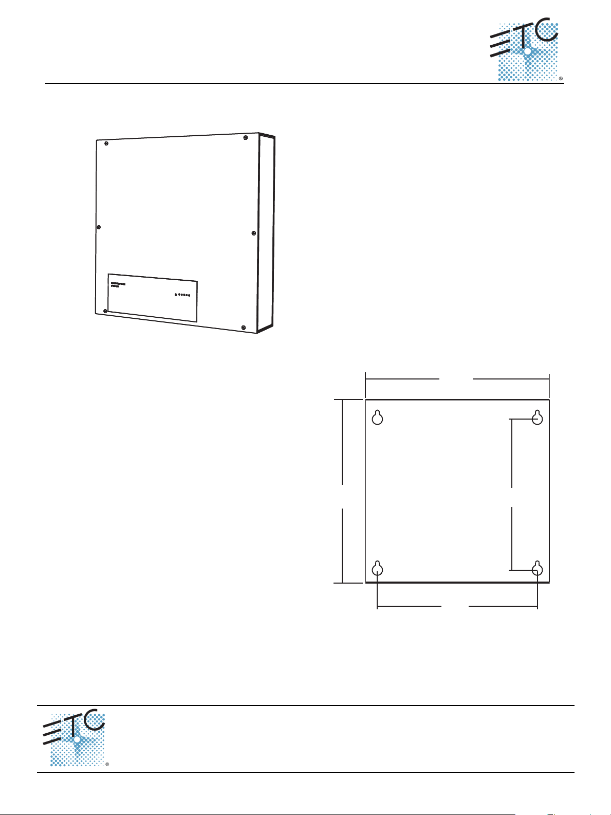
Mount the Unit to the Wall
Step 1: Remove the front cover of the unit
to reveal the four mounting
keyholes.
Step 2: Use the measured keyhole
dimensions located in the graphic
to mark the hole locations for the
mounting hardware.
Step 3: Drill the holes and install the
mounting hardware.
• Mounting hardware is not
supplied.
• Expose at least 1” (25mm) of
threads for mounting the unit.
Step 4: A
ttach the station power supply to
the mounting hardware and
tighten the mounting hardware for
a secure installation.
14”
356mm
14”
356mm
11.5”
292mm
12.2”
310mm
Corpora te H eadquarter s
London, UK
Rome, IT
Holzkirch en, DE
Hong Kon g Rm 1801, 18/F, Tower 1 Ph ase 1, Enterprise Squ are, 9 Sheung Yuet Roa d, Kowloon Bay, Kowloon, Hong Kong Tel +852 2799 1220 Fa x +852 2 799 9325
Service:
Web:
7182M22 60
Unit 26-2 8, Victoria Industrial E state, Vi ctoria Road, London W3 6UU, UK Tel +44 (0)2 0 8896 1000 Fax +44 (0)2 0 8896 2000
Via Pieve Torina, 48 , 00156 Rome , Italy Tel +39 (06 ) 32 111 683 Fax +44 (0) 2 0 8752 8486
(Amer icas) service@etcconnect.com
www.etcconnect.com
Rev B Rele ased 2010 -10 ETC intend s this document to be pr ovided in its e ntirety.
3031 P leasant Vi ew Road, P.O. Box 6 20979, Middleton, Wisconsin 53562-097 9 USA Tel +608 831 4116 Fax +608 836 1736
Ohms trasse 3, 8360 7 Holzkirchen, Ge rmany Tel +49 (80 24) 47 0 0-0 Fax +49 (80 24 ) 47 00-3 00
Copyright © 2010 ETC. All Rights Reserved. Product inf ormation and specific ations subject to change.
(UK) service@etceur ope.com (DE) te chserv-hoki@etcconnect.com
(Asia) se rvice@etcasia.com
.cnI ,slortnoC ertaehT cinortcelE4 fo 1 egaPediuG puteS retaepeR tnuoM llaW mgidaraP
ETC Setup Guide
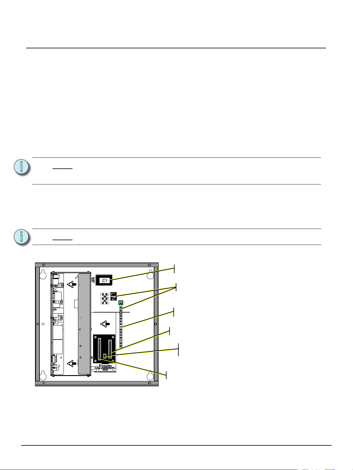
Voltage selector (115 or 230/240 VAC)
AC Input (2 wire + ground)
LinkPower on removable, pluggable connector
Aux power on removable, pluggable connector
LinkPower input from the Paradigm Station
Power Module (SPM)
Ground bus - terminate station ground here
Rough-In Conduit and Wiring
The wall mount enclosure is provided with knockouts on top and bottom for conduit access into the unit.
All wiring terminations are accessible from the front of the unit with the cover removed.
Required terminations include -
• A single phase 115 VAC, 230 VAC, or 240 VAC power input (two wire) which terminates to the
power input terminal block, plus a ground wire which terminates to the ground bar screw terminal.
• LinkPower (Belden 8471 or approved equal) for the station communication bus. All stations must
be grounded by using grounded metal conduit or a 14 AWG ESD drain wire per run. Two
LinkPower wire runs are required including:
• One run from the associated Paradigm Station Power Module (P-SPM) which terminates
on the two pin header labeled J2 on the repeater I/O board.
• One LinkPower run (or more as desired) for station data and power out. These runs
terminate to the removable pluggable connector labeled LON on the repeater I/O board.
Paradigm Wall Mount Repeater
Note:
• 24Vdc auxiliary power to the control station(s). Auxiliary power requires two 16 AWG (1.5mm
stranded wires which terminate to the removable pluggable connector labeled “AUX” on the
repeater I/O board. Auxiliary wire are topology-free. A maximum auxiliary voltage run is
dependant by the wire gauge and the distribution of auxiliary load determined by installation. The
auxiliary supply is capable is of 36W (1.5A at 24Vdc).
Note:
Terminate Wiring
LinkPower includes one pair of wires (data+ and data -). The total combined length of
a LinkPower wire run cannot exceed 1,640 feet (500m), with a maximum distance of
1,313 feet (400m) between any two devices.
2
)
All low voltage control cables must run in separate conduit from power wires.
The Paradigm repeater and dual repeater is supplied with a voltage regulator for selection of either
115 VAC or 230/240 VAC operation; a single phase (2 wire plus ground) AC input terminal; a pluggable
connector for LinkPower data input from the associated Paradigm Station Power Module; and a
pluggable connector each for LinkPower data and Auxiliary power out to the Paradigm control stations.
Paradigm Wall Mount Repeater Setup Guide Page 2 of 4 Electronic Theatre Controls, Inc.
 Loading...