

Page 1
ETC® Setup Guide
Paradigm Rack Mount Repeater Installation
Paradigm Rack Mount Repeater
The Paradigm rack mount repeater can contain a single or dual repeater. Installation procedures for the
single or dual repeater unit are identical.
The Paradigm repeater is designed for use with a Paradigm control system to supply LinkPower for up
to 62 Paradigm control stations on the topology-free and polarity-independent LinkPower control
network.
Rack Mount Installation
Install Unit in Equipment Rack
Step 1: Locate the included rack mounting hardware kit including the mounting screws and
washers.
Step 2: Use the hardware provided to mount the unit to the mounting rails in your equipment rack.
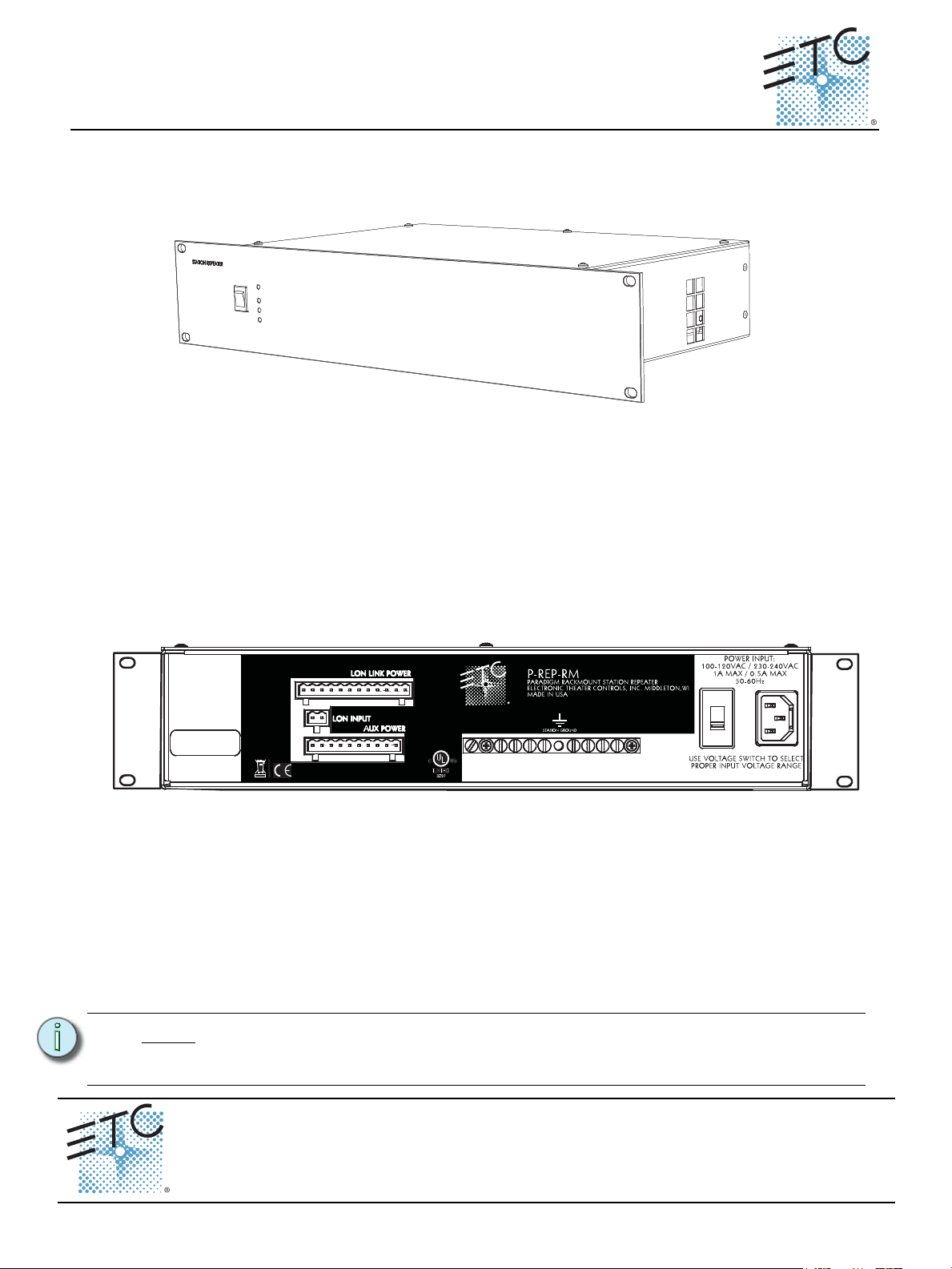
Power and Control Wiring
The rack mount enclosure is provided with wiring connections on the rear of the unit. Required
terminations include:
• Connect a single phase 115 VAC, 230 VAC, or 240 VAC power input to the IEC connector.
• LinkPower (Belden 8471 or approved equal) for the station communication bus. All stations must
be grounded by using grounded metal conduit or a 14 AWG ESD drain wire per run. Two
LinkPower wire runs are required including:
• One run from the associated Paradigm Station Power Module (P-SPM) which terminates
on t
he two pin header labeled J2 on the repeater I/O board.
• One LinkPower run (or more as desired) for station data and power out. These runs
terminate to the removable pluggable connector labeled LON on the repeater I/O board.
Note:
LinkPower includes one pair of wires (data+ and data -). The total combined length of
a LinkPower wire run cannot exceed 1,640 feet (500m), with a maximum distance of
1,313 feet (400m) between any two devices.
Corporate Headquarters
London, UK
Rome, IT
Holzkirchen, DE
Hong Kon g Rm 1801, 18/F, Tower 1 P hase 1, E nterprise S quare, 9 Sheung Yuet Road, K owloon Bay, Kowloon, Ho ng Kong Tel +8 52 2799 1220 Fa x +852 2 799 9325
Service:
Web:
7182M2261
Unit 26-28, Victoria Industr ial Estate, Victo ria Road, London W3 6UU, UK Tel +44 (0)20 8896 1000 Fax +44 (0 )20 8896 2000
Via Pieve Tori na, 48, 00156 Rome, Italy Tel +39 (06) 32 111 683 Fax +44 (0 ) 20 8752 8486
(Americas) service@etcconnect.c om
www.etcconnect.com
Rev A Released 2010-10 ETC intend s this document to be pro vided in its entiret y.
3031 Ple asant View Road, P.O. Box 620979, Middleton, Wisconsin 53562-0979 USA Tel +608 831 4116 Fax +608 836 1736
Ohmstrasse 3, 83607 Holzkirchen, Germany Tel +49 (80 24) 47 00-0 Fax +49 ( 80 2 4) 47 00-3 00
Copyright © 2010 ETC. All Right s Reserv ed. Product information and specifications subject to change.
(UK) service@etceurope.com (DE) techser v-hoki@etcconnect. com
(Asia) service@etc asia.com
.cnI ,slortnoC ertaehT cinortcelE3 fo 1 egaPediuG puteS retaepeR tnuoM kcaR mgidaraP
Page 2
ETC Setup Guide
B A B A B A B A B A B A
1 2
• 24Vdc auxiliary power to the control station(s). Auxiliary power requires two 16 AWG (1.5mm2)
stranded wires which terminate to the removable pluggable connector labeled “AUX” on the
repeater I/O board. Auxiliary wire are topology-free. A maximum auxiliary voltage run is
dependant by the wire gauge and the distribution of auxiliary load determined by installation. The
auxiliary supply is capable is of 36W (1.5A at 24Vdc).
Terminate Wiring
LinkPower (LON®) Control Wiring
Paradigm Rack Mount Repeater
Note:
Unison control stations communicate with the Paradigm architectural control processor using the
LinkConnect station communication bus from the architectural control processor to the stations.
LinkConnect is based on Echelon
LinkConnect is referred to by the protocol it uses, LinkPower.
Note:
All low voltage control cables must run in separate conduit from power wires.
®
LonWorks® with LinkPower. Throughout this document,
LinkPower wiring is topology-free and polarity-independent, you can install your
LinkPower data runs in any desired combination of bus, star, loop, and home run. The
total combined length of LinkPower wire run cannot exceed 1,640 feet (500m), with a
maximum distance of 1,313 feet (400m) between any two un-repeated communicating
devices.
LinkPower Input from P-SPM
Step 1: Pull a single run of Belden 8471 (or approved equal) control wiring to the rear panel from
the associated Paradigm Station Power Module.
Step 2: Strip 3/16” (4.8mm) of insulation from the ends of each wire pair.
Step 3: Remove the 2 pin connector (labeled “LON IN”) from J2 on the rear panel.
Step 4: Loosen the terminal screws and insert the wires into the terminals.
• Insert the white (typical) wire from the pair into the “A” terminal on the connector.
Tighten the screw firmly to secure the wire into the terminal.
• Insert the black (typical) wire from the pair into the “B” terminal on the connector.
Tighten the screw firmly to secure the wire into the terminal.
Step 5: Replace the connector to the rear panel.
Step 6: A 14 AWG ground wire, if wiring is not installed in grounded metal conduit, terminates to
the ground bus located on the rear panel.
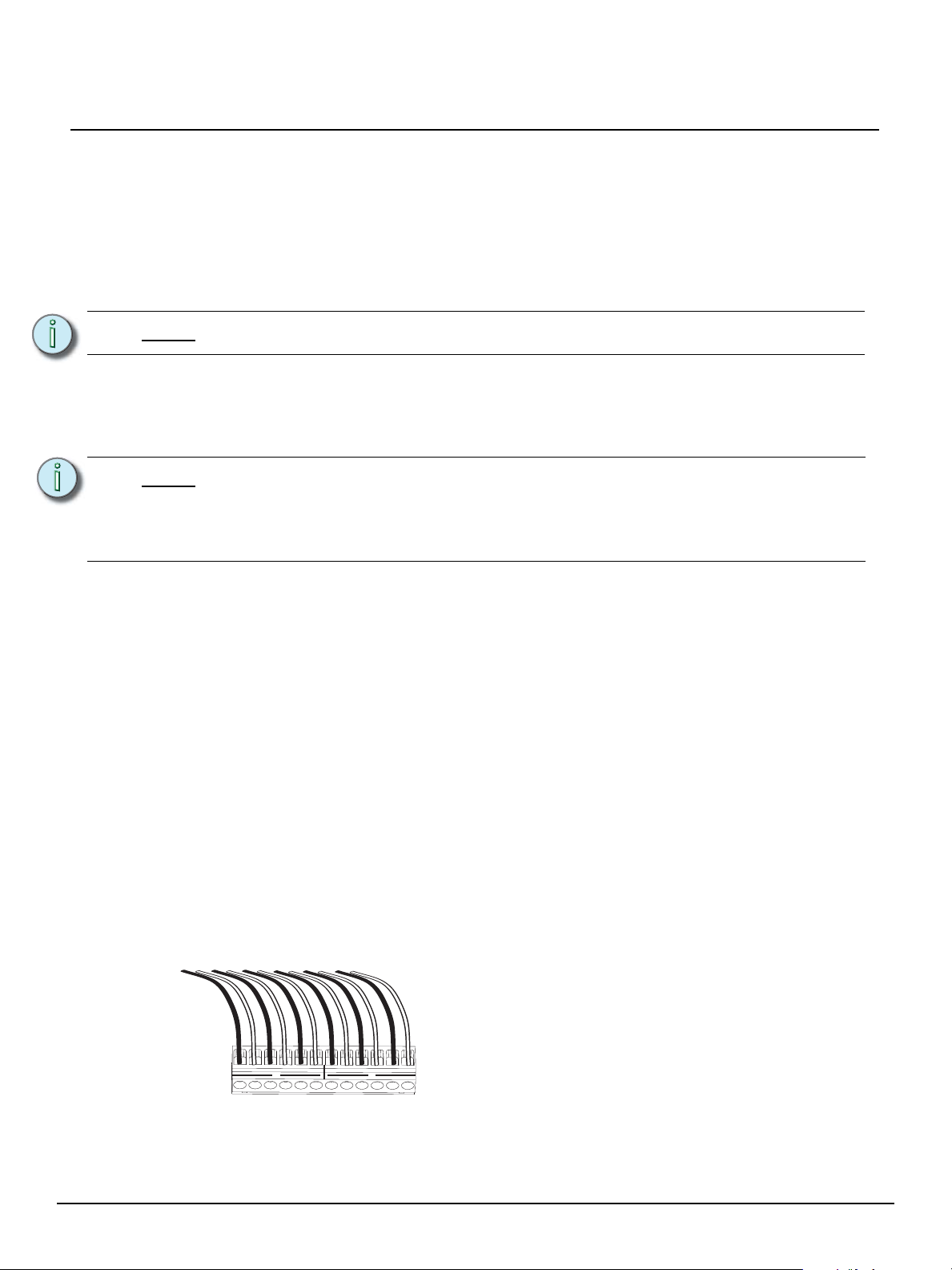
LinkPower Out to Paradigm Stations
Step 1: Pull Belden 8471 (or approved equal) control wiring to the rear panel.
Step 2: Strip 3/16” (4.8mm) of insulation from the ends of each wire pair.
Step 3: Remove the LinkPower connector (labeled LON) from J3 on the rear panel.
Notice the LinkPower/LON connector is labeled to
indicate that the connector is split between two LON
segments (1 and 2). This is effective only when a
Paradigm dual station repeater module (P-DREP) is
used. With the standard Paradigm station repeater
module (P-REP) all six station home runs connect to the
single LON control segment.
Step 4: Loosen the terminal screws for the wire pairs you are terminating.
Step 5: Insert each white (typical) wire from the pairs into a “A” terminal on the connector and
tighten the screw(s) firmly to secure the wire into the terminal.
Paradigm Rack Mount Repeater Setup Guide Page 2 of 3 Electronic Theatre Controls, Inc.
Page 3

ETC Setup Guide
- + - + - + - + - +
Step 6: Insert each black (typical) wire from the pairs into a “B” terminal on the connector and
tighten the screw(s) firmly to secure the wire into the terminal.
Step 7: Replace the connector to the rear panel.
Step 8: A 14 AWG ground wire, if wiring is not installed in grounded metal conduit, terminates to
the ground bus located inside the enclosure.
Terminate Auxiliary Power
Auxiliary power is required when you are installing powered Unison control stations. ETC recommends
using two 16 AWG stranded wires for 24 Vdc auxiliary power to the control station(s). Auxiliary power is
topology-free. Maximum auxiliary voltage runs are dependant by the wire gauge and the distribution of
auxiliary load determined by installation. The auxiliary supply is capable of providing 36W (1.5A at
24Vdc).
Paradigm Rack Mount Repeater
The auxiliary power connector (labeled Aux Power)
provides termination for up to 20 wires in the ten position
pluggable connector. Each terminal allows up to two 16
AWG wire and provides 24 Vdc power to Unison control
stations.
Step 1: Pull auxiliary control power wiring (typically 16 AWG red / black wire pair) into the
equipment rack.
Step 2: Strip 3/16” (4.8mm) of insulation from the ends of each wire pair.
Step 3: Remove the auxiliary power connector from the I/O board.
Step 4: Loosen the terminal screws for the auxiliary wire pairs you are terminating.
Step 5: Insert the black (typical) auxiliary power wire from the pair into a “-” terminal on the
connector and tighten the screw(s) to secure the wire into the terminal.
Step 6: Insert the red (typical) auxiliary power wire from the pair into a “+” terminal on the
connectors and tighten the screw(s) to secure the wire into the terminal.
Step 7: Replace the connector on the I/O board.
Final Installation
Step 1: Supply power to the unit.
Step 2: Check status indicators for faults.
Status Indicators
When power is applied to the Station Repeater Module, the LEDs located on the front panel illuminate,
indicating the status of the auxiliary power, LinkPower control network, and connected stations.
The Aux Power and LinkPower LEDs indicate in green when the Paradigm station power module is
connected properly and auxiliary power and LinkPower are present. When there is an unbalance in
LinkPower the fault indicators illuminate. This condition typically means that the station wiring has a
fault, however it could mean a connected device is having an issue. A qualified technician should
inspect the system wire and terminations first, then proceed to disconnecting devices to pinpoint the
fault and correct it. The power supply will update the fault indicators automatically when the fault
condition is cleared.
• If the NET A line has a fault (is shorted or has leakage to ground), the Fault + LED lights.
• If the NET B line has a fault (is shorted or has leakage to ground), the Fault - LED lights.
• If neither fault LED is illuminated the data connections are properly installed and the stations are
receiving the data and power required for operation.
Paradigm Rack Mount Repeater Setup Guide Page 3 of 3 Electronic Theatre Controls, Inc.
 Loading...