

ETC Unison Paradigm P-TS7 Installation Manual

ETC® Installation Guide
Unison Paradigm® P-TS7 Rack Panel
P-TS7 Rack Panel Page 1 of 4 Electronic Theatre Controls, Inc.
Corporate Headquarters
3031 Pleasant View Road, P.O. Box 620979, Middleton, Wisconsin 53562-0979 USA Tel +608 831 4116 Fax +608 836 1736
London, UK
Unit 26-28, Victoria Industrial Estate, Victoria Road, London W3 6UU, UK Tel +44 (0)20 8896 1000 Fax +44 (0)20 8896 2000
Rome, IT
Via Pieve Torina, 48, 00156 Rome, Italy Tel +39 (06) 32 111 683 Fax +44 (0)20 8896 2000
Holzkirchen, DE
Ohmstrasse 3, 83607 Holzkirchen, Germany Tel +49 (80 24) 47 00-0 Fax +49 (80 24) 47 00-3 00
Hong Kong Rm 1801, 18/F, Tower 1 Phase 1, Enterprise Square, 9 Sheung Yuet Road, Kowloon Bay, Kowloon, Hong Kong Tel +852 2799 1220 Fax +852 2799 9325
Service:
(Americas) service@etcconnect.com
(UK) service@etceurope.com (DE) techserv-hoki@etcconnect.com
(Asia) service@etcasia.com
Web:
www.etcconnect.com
Copyright © 2015 ETC. All Rights Reserved. Product information and specifications subject to change.
7184M2190
Rev A Released 2015-01 ETC intends this document to be provided in its entirety.
Overview
The Unison Paradigm® P-TS7 Touchscreen can be installed in an equipment rack using a rack panel,
which is shipped separately. It is powered by either LinkPower with auxiliary power or by PoE (Power
over Ethernet 802.3af).
• Echelon
®
LinkPower® (LinkConnect) control network using Belden 8471 (or approved equal) and
24 Vdc Auxiliary power (two 16 AWG 1.5mm
2
) wires.
• PoE (Power Over Ethernet 802.3af) using Category 5 cable (or approved equal).
Control wiring should only be installed and terminated by a qualified technician and should follow
standard wiring installation practices. Leave approximately 10 inches (254mm) of wiring in the backbox
for connection and to allow slack for future service needs. For more information about terminating CAT5
cable, refer to the ETC Ethernet Cat5 Termination Kit Setup Guide.
Install Collar in Rack Panel
Installation should follow local codes and standard practices. Ensure that all wiring is installed correctly.
The touchscreen is supplied with an installation kit which includes the necessary hardware and
electrical supplies.
Step 1: Slide the collar into the rack panel.
Step 2: Install and tighten four M4 x 20mm collar mount screws through the collar and into the
rack panel.
Paradigm Touchscreen Model
Model Description
P-TS7-RM Paradigm Touchscreen Rack Panel
Note:
It is important to orient the rack panel with the cutout on the right side to provide better
cable access between the touchscreen and the Termination PCB.
In addition, the collar should be installed with the stamped arrow (
) pointing up.
Mounting
Pin
Cutout on
right side
ETC Installation Guide
P-TS7 Rack Panel
P-TS7 Rack Panel Page 2 of 4 Electronic Theatre Controls, Inc.
Install the Termination PCB
The printed circuit board (PCB) assembly is designed to accommodate either Ethernet or LON
connections. Prior to installing the PCB, terminate all necessary wiring. The PCB is installed on the
back (inside) of the rack panel.
The PCB consists of three parts:
• PCB with female RJ11, LinkPower connector, 24 Vdc (Aux) connector, and ground spade
• RJ45 with punch down wire termination
• Mounting bracket and screws
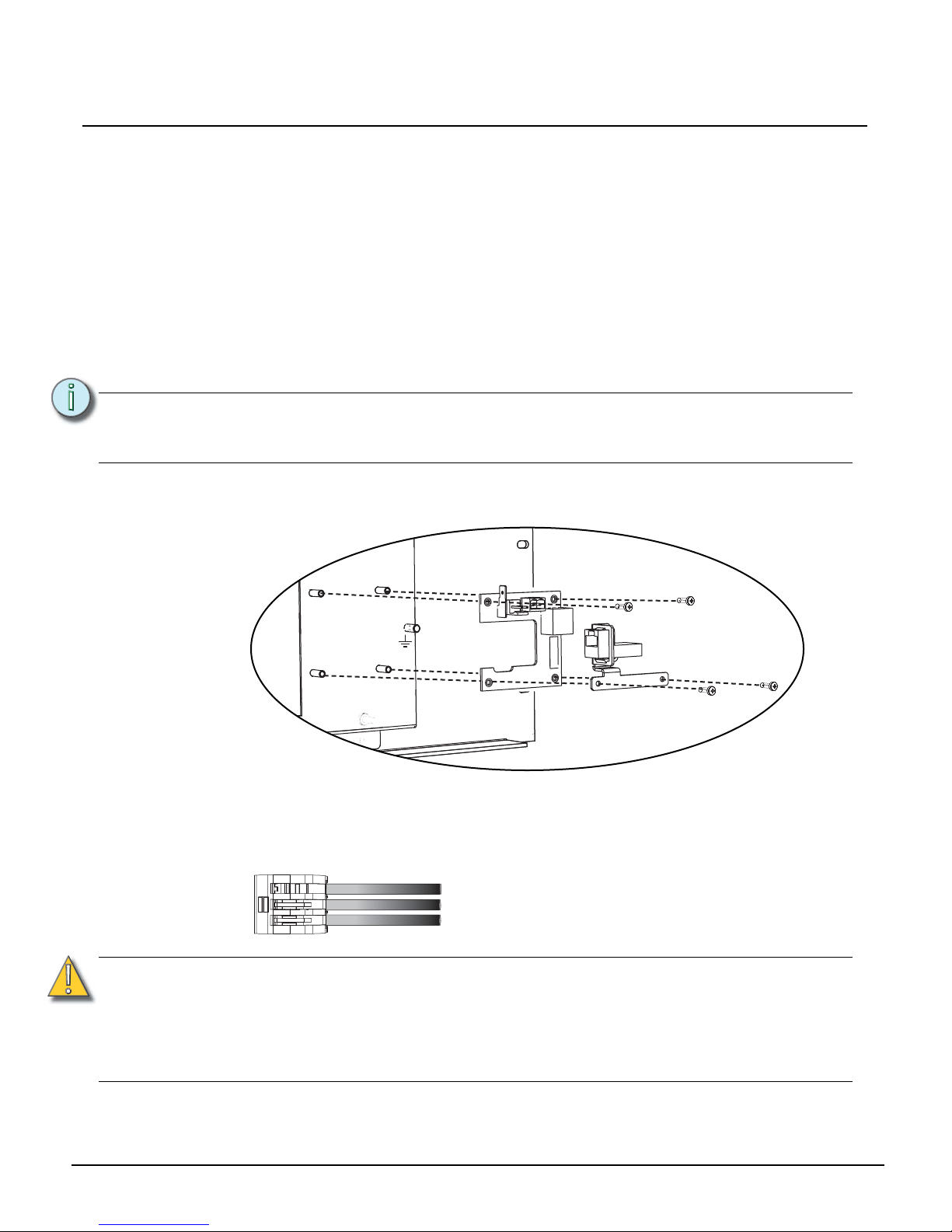
Installing the Termination PCB on the Rack Panel
Step 1: Position the PCB on the four standoffs on the back of the rack panel and secure with two
M3x10mm pan head screws on the RJ11 side of the PCB only.
Step 2: Place the bracket and RJ45 assembly (if used) on top of the PCB. Secure the PCB to the
backbox through the remaining two holes in the PCB with M3x10mm pan head screws.
Step 3: A ground connection is required for all touchscreen assemblies. Using one three position
WAGO connector, connect the (typically green and yellow) installed wire(s) with the
ground wire pigtail (with attached spade), provided in the installation kit, and the ground
wire attached to the rack panel.
Note:
The termination PCB can be installed in any orientation to accommodate wiring.
Orienting the PCB with the ground and LinkPower connections toward the top of the
rack (as illustrated) will simplify installation.
CAUTION:
Only one network type (LON or Ethernet) may be connected to the touchscreen at a
time. Do not connect both Auxiliary power and PoE.
ETC requires that all backboxes and touchscreens are grounded in accordance with
local electrical codes.
The RJ11 connection must be used to provide a ground connection from the backbox
to the touchscreen even when Ethernet connectivity is used.
Installed ground wire
Ground wire pigtail (spade connector to the termination PCB)
Ground wire pigtail (ring terminal connected to the rear rack panel)
 Loading...