

Page 1
ETC Installation Guide
The Paradigm Occupancy Sensor provides 360 degree coverage
of the installed location and is available in three models:
• P-OCC-SR- Occupancy Sensor with small room lens covers 450 sq. ft.
at 8 ft./ 800 sq. ft. at 10 ft.
• P-OCC - Occupancy Sensor with standard room lens covers
1,800 sq. ft. at 8 ft./ 3,000 sq. ft. at 10 ft.
• P-OCC-HC - Occupancy Sensor with high ceiling lens covers 300 sq. ft.
at 10 ft./ 7,000 sq. ft. at 40 ft.
Each sensor is available in neutral white or black finish. Lens
masks are provided to allow customized occupancy detection
fields as required by each installation.
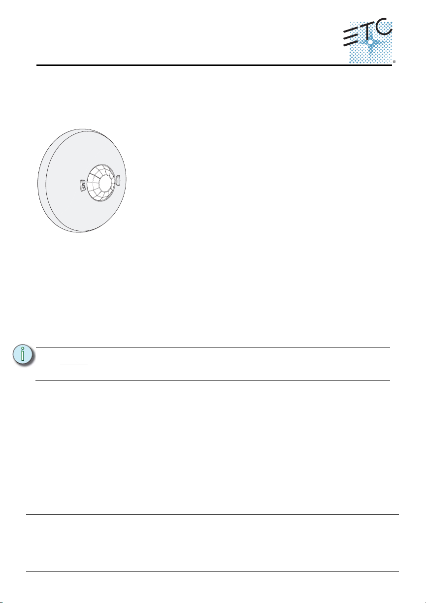
Unison Paradigm® Occupancy Sensor
Overview
The Unison Paradigm® Occupancy Sensor is a ceiling mounted sensor that utilizes
passive infrared (PIR) technology; providing reliable vacancy and occupancy
detection for lighting control. Paradigm Occupancy Sensors integrate with Paradigm
lighting control systems, providing energy efficient lighting control solutions.
Wire Specification
The Paradigm Occupancy Sensor utilizes LinkConnect to power the sensor and to
provide data to and from the connected Paradigm control system. LinkConnect is
topology-free and polarity independent. You can install your data runs in any desired
combination of bus, star, loop, and home-run. ETC recommends using Belden 8471
(or equivalent) wire. The total combined length of a LinkConnect wire run may not
exceed 1,640 feet (500m), with a maximum distance of 1,312 feet (400m) between
any two devices.
Note:
ETC requires that all sensors be grounded by using a 14 AWG
(2.5mm2) ESD drain wire.
All control wiring should be installed and terminated by a qualified installer and should
follow standard wiring installation practices, and meet local codes. Leave
approximately 10 inches (254mm) of wiring in the junction box or tied back in the
ceiling to allow for wiring connections and future service needs.
Corporate Headquarters
London, UK
Unit 26-28, Victoria Industrial Estate, Victoria Road, London W3 6UU, UK Tel +44 (0)20 8896 1000 Fax +44 (0)20 8896 2000
Rome, IT
Via Pieve Torina, 48, 00156 Rome, Italy Tel +39 (06) 32 111 683 Fax +44 (0)20 8752 8486
Holzkirchen, DE
Hong Kong Rm 1801, 18/F, Tower 1 Phase 1, Enterprise Square, 9 Sheung Yuet Road, Kowloon Bay, Kowloon, Hong Kong Tel +852 2799 1220
Service:
(Americas) service@etcconnect.com
Web:
www.etcconnect.com
7184M2160
Rev B Released 2013-01 ETC intends this document to be provided in its entirety.
Occupancy Sensor Installation Guide Page 1 of 8 Electronic Theatre Controls, Inc.
3031 Pleasant View Road, P.O. Box 620979, Middleton, Wisconsin 53562-0979 USA Tel +608 831 4116 Fax +608 836 1736
Ohmstrasse 3, 83607 Holzkirchen, Germany Tel +49 (80 24) 47 00-0 Fax +49 (80 24) 47 00-3 00
Copyright © 2013 ETC. All Rights Reserved. Product information and specifications subject to change.
(UK) service@etceurope.com (DE) techserv-hoki@etcconnect.com
(Asia) service@etcasia.com
Page 2

ETC Installation Guide
Occupancy Sensor
Installation Environment
Paradigm Occupancy Sensors are intended for installation to a finished ceiling
surface, ceiling tile mounted, attached to a round fixture junction box or single-gang
RACO switch box. The sensor operates in ambient temperatures of -10°C to 40°C,
non-condensing humidity.
ETC recommends paying special attention to the installation environment:
• The sensor must have an unobstructed view of the room. Do not mount behind or near tall
cabinets, shelves, hanging light fixtures, etc.
• Do not install the sensor within 8 feet from an HVAC airflow duct / vent.
• Install the sensor where it cannot easily sense movement in areas outside of the intended
space, such as hallways, glass partitions, or adjacent rooms. If the installation location
cannot avoid these conditions, portions of the lens can be masked to block the sensor view
of these undesired areas. Reference "Lens Masking" on page 5.
Parts and Supplies
The following parts and supplies are included with the Unison Paradigm® Occupancy
Sensor ordered:
• soft ceiling tile adaptor • 3 position WAGO connectors
• LinkConnect & ESD ground
wire pigtails
• 3 each lens masks (spare)
Installation
The Paradigm Occupancy Sensor is provided with a twist-lock mounting plate that
can be mounted to a junction box, finished ceiling or soft ceiling tile. Determine the
installation method and follow the detailed instructions:
• See “Junction Box Installation” on page 3.
• See “Soft Ceiling Tile Installation” on page 4.
• 2 each screws, 6-32 x 3/4” and 1 3/4”
Note:
Occupancy Sensor Installation Guide Page 2 of 8 Electronic Theatre Controls, Inc.
The LinkConnect pigtail and WAGO connectors (provided) are only
required when the sensor is installed in series with other stations or
sensors. If you are not continuing the data run, direct termination on the
control board is recommended.
Page 3
ETC Installation Guide
Step 1:Pull the Belden 8471 (or
equivalent) and 14 AWG
(2.5mm
2
) ground wire to the
junction box.
installed control wire
installed control wire to next stati
on
sensor pigtail
a: Strip 3/16” (5mm) of insulation from each installed LON wire.
b: Open the three terminal levers on a WAGO connector and
insert the installed (typically black) Belden 8471 LinkConnect
wire, the black lead from the sensor pigtail, and the
continuing Belden 8471 (typically black) wire into the
terminals.
c: Close the levers onto the wires.
d: Repeat the above for the installed (typically white) Belden
8471 LinkConnect wire and the remaining pigtail from the
sensor, as well as the ESD ground wires using a new WAGO
connector for each termination type.
Occupancy Sensor
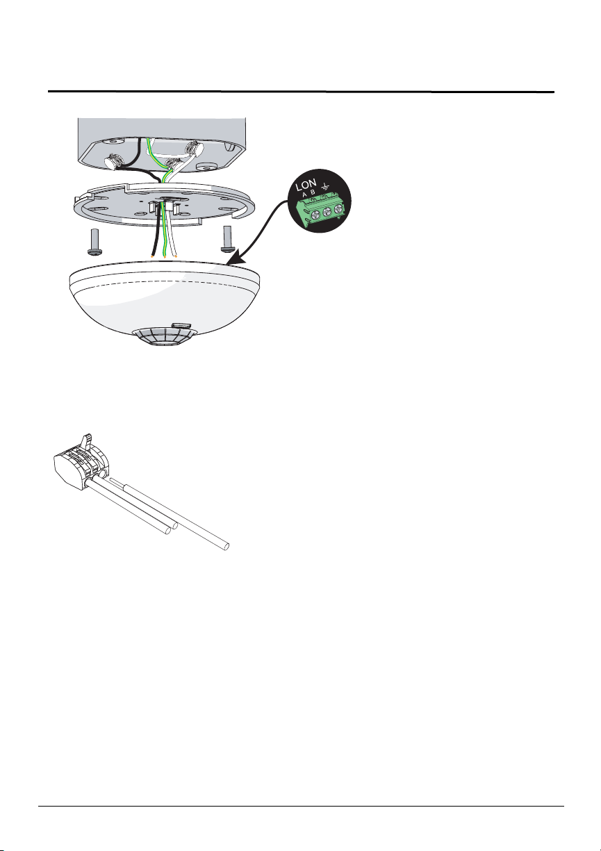
Junction Box Installation
terminate
wires here
Step 2: If you are installing the sensor in series with other sensors or stations
(continuing the data run), use the provided LinkConnect pigtail, ESD ground
pigtail and WAGO connectors to make the terminations. If you are not
continuing the data run, proceed to step 3.
Step 3:Orient the smooth side of the mounting plate to the junction box and pull the
Belden 8471 and the 14 AWG (2.5mm
box through the provided holes near the center of the mounting plate.
Step 4: Secure the mounting place to the junction box using the screws provided (both
short and long screws are included for convenience).
Step 5: Strip each wire 5/16” (8mm) and terminate the white, black, and green (ground)
wires to the terminal block located on the sensor control board. Torque each
termination to 3.1-3.5 in-lb.
a: Terminate the white incoming wire to terminal A.
b: Terminate the black incoming wire to terminal B.
c: Terminate the green wire to the ground terminal.
Step 6:Attach the sensor to the mounting plate by aligning the tabs on the sensor with
Occupancy Sensor Installation Guide Page 3 of 8 Electronic Theatre Controls, Inc.
the slots on the mounting plate, then twist clockwise until the two are locked
into place.
2
) ESD ground wire from the junction
Page 4

ETC Installation Guide
poke the adapter through the ceiling tile, then bend
it over for a secure fit.
LinkConnect pigtail and
WAGO connectors
(optional use)
terminate
wires here
installed control wire
installed control wire to next stati
on
sensor pigtail
a: Strip 3/16” (5mm) of insulation from each installed wire.
b: Open the three terminal levers on a WAGO connector
and insert the installed (typically black) Belden 8471
LinkConnect wire, the black lead from the sensor pigtail,
and the continuing Belden 8471 (typically black) wire
into the terminals.
c: Close the levers onto the wires.
d: Repeat the above for the installed (typically white)
Belden 8471 LinkConnect wire and the remaining pigtail
from the sensor, as well as the ESD ground wires using
a new WAGO connector for each termination type.
Occupancy Sensor
Soft Ceiling Tile Installation
Step 1:Pull the Belden 8471 (or equivalent) and 14 AWG (2.5mm2) ground wire to the
installation location.
Step 2:Orient the smooth side of the mounting plate to the ceiling tile and insert the
soft ceiling tile adaptor through the two small holes near the center of the
mounting plate.
Step 3:Poke the adaptor tines through the ceiling tile, then bend each tine over in
opposite directions for a secure fit.
Step 4: If you are installing the sensor in series with other sensors or stations
(continuing the data run), use the provided LinkConnect pigtail, ESD ground
wire pigtail and WAGO connectors to make the terminations. If you are not
continuing the data run, proceed to step 5.
Occupancy Sensor Installation Guide Page 4 of 8 Electronic Theatre Controls, Inc.
Page 5

ETC Installation Guide
Step 1:As needed, trim the lens mask to fit the desired
area to be blocked.
Step 2: Gently press down on the sensor lens, which
will give only slightly, and insert the lens
mask.
Step 3:Rotate the lens mask around
the dome to block the required
area from occupancy
sensing.
Occupancy Sensor
Step 5:Create a hole for wire pass-through in the ceiling tile by poking through the
center hole or oblong hole of the mounting plate, then pull the wires through.
Step 6: Strip each wire 5/16” (8mm) and terminate the white, black, and green (ground)
wires to the LON terminal block located on the sensor control board. Torque
each termination to 3.1-3.5 in-lb.
a: Terminate the white incoming wire to terminal A.
b: Terminate the black incoming wire to terminal B.
c: Terminate the green wire to the labeled ground terminal.
Step 7:Attach the sensor to the mounting plate by aligning the tabs on the sensor with
the slots on the mounting plate, then twist clockwise until the two are locked
into place.
Lens Masking
Lens masks are provided in the packaging for your convenience.
Occupancy Sensor Installation Guide Page 5 of 8 Electronic Theatre Controls, Inc.
Page 6

ETC Installation Guide
Occupancy Sensor
Power Up and Test
Power Up
For power to be applied to the Paradigm Occupancy Sensor, any additional
LinkConnect terminations for the system must also be made. In addition, the
Paradigm Architectural Control Processor (P-ACP) and Station Power
Module (P-SPM) must be installed in the host DRd or ERn rack enclosure.
When the sensor is powered up the PIR LED will illuminate for one minute for
calibration and warm-up, then will return to normal operation and enter walk test
mode if desired.
Binding Sensors to Paradigm
The Paradigm Architectural Control Processor (P-ACP) to which this sensor is
physically wired to must learn, or be told, the station hardware address (known as a
neuron ID). When the sensor is unbound from the connected P-ACP, the service pin
LED blinks.
The neuron ID is labeled on the sensor control board and can be manually entered
into the configuration using LightDesigner software. Alternatively, the sensor can be
identified using the [Service Pin] button (designated with “S” on the button) and by
the connected Paradigm ACP using its [LonWorks Connections] menu. Reference
the related source documentation, either the LightDesigner Online Help System or
the Unison Paradigm Architectural Control Processor Configuration Manual;
specifically the section on Arch Setup Menu, LonWorks Connections.
Tes t
Unison Paradigm Occupancy Sensors offer a Walk Test mode which shortens the
vacancy / no occupancy timer to 10 seconds, allowing for simple and quick
verification of the sensors coverage and range in the installed space.
Walk-Test mode automatically exits and the sensor returns to normal operation after
5 minutes and can be manually terminated early by pressing the [Walk Test] or
[Service Pin] button on the sensor or alternatively by clicking on the “Wink”
command in LightDesigner.
Enable Walk Test Mode
Step 1:Prepare the site for configuration.
a: Make certain the sensor and lighting loads are powered and connected for
control by the Paradigm control system.
b: You will need direct access to the Paradigm Occupancy Sensor in order to
place it into walk test mode. Alternatively, you can invoke the walk test mode by
sending a Wink command from the connected Paradigm control system.
Reference the LightDesigner Online Help System for instructions to send a
Wink command.
Occupancy Sensor Installation Guide Page 6 of 8 Electronic Theatre Controls, Inc.
Page 7

ETC Installation Guide
Occupancy Sensor
Note:
The sensor must be connected and bound to the Paradigm Architectural
Control Processor (P-ACP) in order to enable Walk Test Mode. See
“Binding Sensors to Paradigm” on page 6.
Step 2:Press the [Walk Test] button on the front
of the sensor to enable the walk test
feature at the sensor. A green LED will
begin to flash, indicating the walk test is
enabled and the vacancy / no vacancy
occupancy timer will be shortened to 10
walk test
walk test
button
button
seconds.
service
Step 3:Move throughout the space including
corners and areas that may specifically
service
button
button
be obscured from line of sight to the
sensor. Each time the sensor detects
movement, the lens will illuminate red.
Step 4:Adjust the lens masking, if installed,
blocking certain areas of the installed
space from sensor detection. See "Lens Masking" on page 5.
Step 5:Walk test mode will automatically exit after five minutes from the time it was
enabled. To manually exit the walk test mode, press either of the buttons on the
sensor.
Verify Vacancy Operation
For systems that have been configured for the installed sensor to control specific
lighting circuits, walk test mode can also be used to verify vacancy operation.
Step 1:Confirm the installing technician has programmed the lighting control system.
Step 2:Enable walk test mode using the instruction above (see "Enable Walk Test
Mode").
Step 3:With walk test mode enabled, exit the room for 15 seconds to allow the 10
second timer to expire.
Step 4:Re-enter the room and confirm the configured vacancy / no occupancy state
was properly recalled.
Step 5:Walk test mode will automatically exit after five minutes from the time it was
enabled. To manually exit the walk test mode, press either of the buttons on the
sensor.
Note:
When in walk test mode, status LEDs will always behave as indicated
above, even if they have been programmed to be off by the system
configuration.
Occupancy Sensor Installation Guide Page 7 of 8 Electronic Theatre Controls, Inc.
Page 8

ETC Installation Guide
High Ceiling side view
0
3.0m
10ft
3.0m
10ft
6.1m
20ft
6.1m
20ft
9.1m
30ft
9.1m
30ft
12.2m
40ft
12.2m
40ft
0
12.2m
40ft
9.1m
30ft
6.1m
20ft
Small Room side view
0
0
1.5m
5ft
1.5m
5ft
3.0m
10ft
3.0m
10ft
4.6m
15ft
4.6m
15ft
6.1m
20ft
6.1m
20ft
8ft
2.4m
10ft
3.0m
12ft
3.7m
Large Room side view
0
8ft
2.4m
10ft
3.0m
12ft
3.7m
0
3.0m
10ft
3.0m
10ft
6.1m
20ft
6.1m
20ft
9.1m
30ft
9.1m
30ft
12.2m
40ft
12.2m
40ft
Occupancy Sensor
Occupancy Sensor Installation Guide Page 8 of 8 Electronic Theatre Controls, Inc.
 Loading...