

Page 1

ETC® Setup and Connect Guide
Unison Paradigm® Central Control Server
Overview
This setup guide will guide you through the setup and connection of the Paradigm Central Control
Server (P-CCS) in a 19” (1U) rack space mounted bracket.
The Paradigm Central Control Server (P-CCS) manages a Unison Paradigm LightDesigner Server
Project, which can contain many sub-projects. The P-CCS enables server level control events that can
affect all of the configured sub-projects, such as system wide preset activations from a centralized
timed event configuration.
Additionally, the P-CCS provides support for integration of the Unison Paradigm Virtual Touchscreen, a
BACnet IP interface, and provides a built-in web interface for remote connection from a web browser.
I/O Panel Connections
The P-CCS uses two hardware interfaces, each with an I/O panel including the following connections:
• RJ45 connection for interface to the ETC lighting network (Net3 Network)
• five USB ports (one on the front of the unit, four on the rear panel)
• RJ45 connection for interface to a secondary building lighting network (BACnet systems and the
Virtual Touchscreen)
• 12V dc power input (power supplies are provided)
General Use Safety
The P-CCS must be mounted in a rack in a horizontal flat orientation, or placed flat on a desk.
Rack Mount Safety
• Elevated Operating Ambient - If installed in a closed or multi-unit rack assembly, the operating
ambient temperature of the rack environment may elevate above the room ambient. Special care
should be taken. Do not operate the processor in an enclosed environment above 100°F (40°C).
• Reduced Air Flow - When installing the processor in an equipment rack, the rack must be vented
and have adequate airflow to maintain an operating temperature below 100°F (40°C).
• Mechanical Loading - Mounting of the equipment in an equipment rack should only be
accomplished using the included ETC rack mount hardware, in a horizontal orientation to assure
even mechanical loading in the rack; avoiding hazardous or dangerous loading conditions.
• Circuit Overloading - Use only the supplied ETC power supplies of 12V dc / 5A to power the
processor. When installed in an equipment rack, consideration should be given to the connection
of the processor to the rack or power source to avoid overloading the rack circuit or supply wiring.
Appropriate consideration of the rack or power distribution in the equipment rack should be
applied during installation.
• Reliable Grounding - Reliable earthing of the rack-mounted equipment should be maintained.
Particular attention should be given to any supply connections other than direct connections to the
branch circuit (e.g. use of power strips).
Corporate Headquarters
London, UK
Rome, IT
Holzkirchen, DE
Hong Kong Rm 1801, 18/F, Tower 1 Phase 1, Enterprise Square, 9 Sheung Yuet Road, Kowloon Bay, Kowloon, Hong Kong Tel +852 2799 1220 Fax +852 2799 9325
Service:
Web:
7180M2260
Unit 26-28, Victoria Industrial Estate, Victoria Road, London W3 6UU, UK Tel +44 (0)20 8896 1000 Fax +44 (0)20 8896 2000
Via Pieve Torina, 48, 00156 Rome, Italy Tel +39 (06) 32 111 683 Fax +44 (0) 20 8752 8486
(Americas) service@etcconnect.com
www.etcconnect.com
Rev C Released 2014-01
3031 Pleasant View Road, P.O. Box 620979, Middleton, Wisconsin 53562-0979 USA Tel +608 831 4116 Fax +608 836 1736
Ohmstrasse 3, 83607 Holzkirchen, Germany Tel +49 (80 24) 47 00-0 Fax +49 (80 24) 47 00-3 00
Copyright © 2014 ETC. All Rights Reserved. Product information and specifications subject to change.
(UK) service@etceurope.com (DE) techserv-hoki@etcconnect.com
ETC intends this document to be provided in its entirety.
(Asia) service@etcasia.com
Paradigm Central Control Server Setup and Connect Guide Page 1 of 4 Electronic Theatre Controls, Inc.
Page 2
ETC Setup and Connect Guide
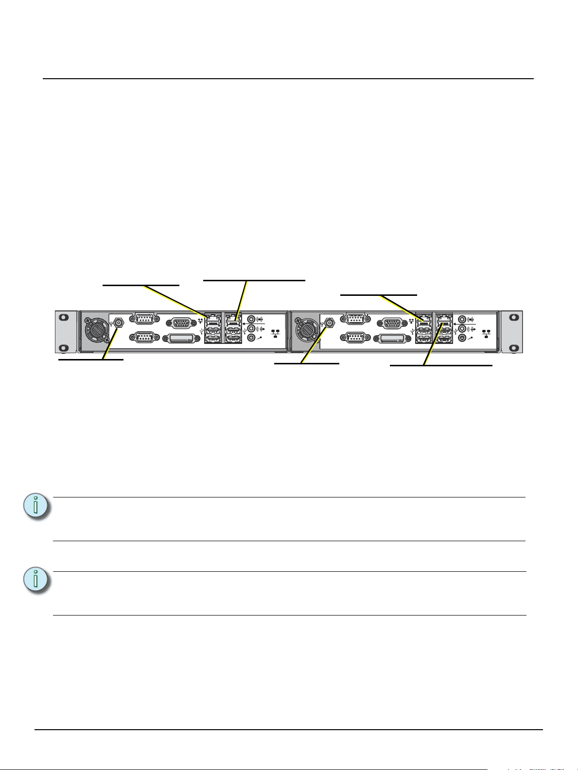
Net3 Conductor rear panel
Paradigm CCS rear panel
+
DVI DVI
Net3 Conductor rear panel
VGA
VGA
SERIAL A RS-232
SERIAL A RS-232
SERIAL B RS-232
SERIAL B RS-232
SECONDARY
NETWORK
SECONDARY
NETWORK
NET3
NETWORK
NET3
NETWORK
ETC NET3 Network
NET3 Network/Switch
• 10/100 Mbps
• Auto-sensing
• RJ45 compatible
ETC NET3 Network
NET3 Network/Switch
Virtual Touchscreen
• 10/100 Mbps
• Auto-sensing
• RJ45 compatible
Power Input
12V dc, 5A max
P-CCS Secondary Network
BACnet Interface / Virtual Touchscreen
• 10/100 Mbps
• Auto-sensing
• RJ45 compatible
* Unlabeled connections are not used.
Net3 Conductor
Secondary Network
External Time Synchronization
• 10/100 Mbps
• Auto-sensing
• RJ45 compatible
Power Input
12V dc, 5A max
Paradigm Central Control Server
Help from Technical Services
If you experience difficulty during setup or installation of the Paradigm Central Control Server, additional
information is available from www.etcconnect.com, or by contacting ETC Technical Services at your
local office listed in the boiler plate of page 1.
Setup and Connect
The Paradigm Central Control Server is provided from the factory pre-installed into a rack mounting
bracket. This bracket installs into a standard 19 inch rack enclosure and requires only one rack unit (1U)
of rack space. Screws, washers and cage nuts are provided for installation convenience. Two 12V dc /
5A power supply kits are also provided.
Paradigm Central Control Server Setup and Connect Guide Page 2 of 4 Electronic Theatre Controls, Inc.
Step 1: Use the provided hardware to secure the P-CCS into the 19 inch rack.
Step 2: Connect an Ethernet cable (not provided) between the Paradigm Central Control Server
Note:
Step 3: Connect an Ethernet patch cable (not provided) between the Net3 Conductor “ETC Net3
Note:
Step 4: Plug the provided DC power input cables into the power input receptacles on the rear
Step 5: Select the appropriate connector (determined by the installation region) from each power
“Net3 Network” connector and the lighting network switch.
If you are using BACnet or Virtual Touchscreen on a network other than the lighting
network, connect an Ethernet patch cable from the P-CCS Secondary Network
connection to a switch of the network where these features are used.
Network” connector and the lighting network switch.
When using an external time server located on a separate network to synchronize the
Paradigm system clock, connect an Ethernet patch cable between the Net3 Conductor
Secondary Network connection and the network switch of the appropriate network.
panel of each unit. Secure these connections by threading the locking nut tight onto the
receptacles and tie back the power supplies in the rack.
supply kit and assemble them to the cables, then to the power supplies. Connect to the
power source and tie back the power supplies in the rack.
Page 3

ETC Setup and Connect Guide
Paradigm Central Control Server
Step 6: Apply power to the units. On the initial power up, the power switch for each unit will
illuminate in blue. If the units do not power up immediately, press the power button located
on the front panel of each unit.
Note:
If power is lost after initial power up, the P-CCS will restore to the previous state when
power is restored. For example, if the power was on at power loss, the unit will return
to an on state when power is restored.
Web Interface
The Paradigm Central Control Server (P-CCS) is provided with built-in web interfaces on each
hardware device, accessible only through the use of an Internet browser.
Step 1: To view the product web interface, first physically connect and configure a computer to
the Net3 network with the Central Control Server.
Step 2: Launch a web browser (Internet Explorer 7 or newer, Chrome, Firefox, etc.).
Step 3: Enter the product IP Address in the url address line of the browser to load the product web
interface. The Paradigm Central Control Server and Net3 Conductor are each provided
with default IP addresses from the factory.
Central Control Server
The Paradigm Central Control Server factory default IP Address is 10.101.10.10. For reference, the
factory default Subnet Mask is 255.255.0.0 and the gateway is 10.101.1.1.
The web user interface provides local interface and configuration of the Paradigm Central Control
Server (P-CCS) and the Paradigm network of products and features that are found in the Server Project
configuration.
• access to all preset and sequence controls in the Server Project
• access to timed event features for viewing, editing, and new event creation
• view of the entire network of projects in the Server Project, their processor and object status
• view and download server-wide log data
• upload a configuration file (*.spcf) from the connected PC
• retrieve a configuration file from the P-CCS
Paradigm Central Control Server Setup and Connect Guide Page 3 of 4 Electronic Theatre Controls, Inc.
Page 4

ETC Setup and Connect Guide
Paradigm Central Control Server
• configure the date and time (the P-CCS acts as a time server to the connected Paradigm
Architectural Control Processors)
• setup an automatic or manual backup of the Server Project Config file (*spcf) log data to the
connected Net3 Conductor
• download the Paradigm VTS installer file
View the P-CCS built-in web help, viewed by selecting “Help” from the web interface menu.
Net3 Conductor
The Net3 Conductor default IP Address is 10.101.50.60 and Subnet mask is 255.255.0.0.
The Net3 Conductor web user interface allows for local interface and configuration of the Net3
Conductor Network Services Gateway.
The web interface provides the following features:
• access to view and set the network IP mode
• access to set and monitor the services provided over the network; such as DNS server, NTP time
server, set file sharing access, and the DHCP server
• ability to enable logging features, including saving and clearing data and setup of log backup
destinations
• generate a backup of the current configuration and upload a configuration
• ability to upgrade Net3 Conductor software
Reference the Net3 Conductor built-in web help, viewed by clicking “Help” from the navigation links on
the left of the web interface.
Paradigm Central Control Server Setup and Connect Guide Page 4 of 4 Electronic Theatre Controls, Inc.
 Loading...