

Page 1

Unison Mosaic Show Control
Hardware Installation Guide
Rev D
Copyright © 2009-12 Electronic Theatre Controls, Inc..
Product information and specifications subject to change.
Part Number: 7180M2120 Rev D.
All rights reserved.
Released: 2012-08.
Page 2

ETC permits the reproduction of materials in this manual only for non-commercial purposes.
All other rights are reserved by ETC.
2
Page 3

CONTENTS
Contents............................................................................................................. 3
Welcome.............................................................................................................5
Overview............................................................................................5
Software installation........................................................................ 5
QuickTime.........................................................................................5
Sample media.................................................................................... 5
MSC installation & hardware reference....................................................... 6
MSC installation............................................................................... 6
MSC layout........................................................................................ 6
MSC versions.................................................................................... 6
Power supply & grounding............................................................. 7
Realtime clock battery.................................................................... 8
Memory card.................................................................................... 8
Status LEDs & error codes............................................................8
Reset switch & watchdog...............................................................9
Ports................................................................................................. 10
TPC installation & hardware reference..................................................... 14
TPC installation.............................................................................. 14
TPC layout.......................................................................................14
Power supply...................................................................................15
Realtime clock battery..................................................................15
Memory card...................................................................................16
Status LEDs & error codes..........................................................16
Reset switch, config switch & watchdog...................................17
Learning IR receiver.......................................................................17
MSC X installation & hardware reference................................................ 18
MSC X installation.........................................................................18
MSC X layout..................................................................................18
MSC X versions..............................................................................18
Power supply & grounding........................................................... 19
Realtime clock battery..................................................................19
Memory card.................................................................................. 19
Status LEDs..................................................................................... 20
Error codes..................................................................................... 20
Reset switch....................................................................................20
Watchdog........................................................................................ 21
Ports................................................................................................. 21
AVC installation & hardware reference.....................................................24
AVC installation............................................................................. 24
AVC layout...................................................................................... 24
Power supply & grounding........................................................... 25
Realtime clock battery..................................................................26
Memory card.................................................................................. 26
Status LEDs & error codes......................................................... 26
Reset switch & watchdog............................................................ 27
Video systems................................................................................ 27
Ports................................................................................................. 28
3
Page 4

RIO installation & hardware reference...................................................... 30
RIO installation.............................................................................. 30
RIO layout....................................................................................... 30
RIO versions................................................................................... 30
Power supply & grounding........................................................... 31
Status LEDs & error codes..........................................................31
Address wheel................................................................................32
Reset switch & watchdog............................................................ 32
Ports................................................................................................. 32
BPS installation & hardware reference...................................................... 36
BPS installation............................................................................... 36
BPS versions....................................................................................36
BPS layout........................................................................................37
Power supply...................................................................................37
Status LEDs..................................................................................... 37
Error codes..................................................................................... 38
Address wheel................................................................................38
Reset switch & watchdog.............................................................38
Learning IR receiver.......................................................................38
NET installation & hardware reference..................................................... 40
NET installation..............................................................................40
NET layout.......................................................................................40
Power supply...................................................................................40
Power supply choice & loading...................................................41
Grounding........................................................................................41
Status LEDs..................................................................................... 41
OPTO installation & hardware reference................................................. 42
OPTO installation..........................................................................42
OPTO layout...................................................................................42
Power supply...................................................................................42
Grounding....................................................................................... 43
Status LEDs..................................................................................... 43
DMX Thru termination................................................................ 43
DMX & RDM guidelines.............................................................. 43
LED installation & hardware reference..................................................... 44
LED installation.............................................................................. 44
LED layout.......................................................................................44
LED versions...................................................................................44
Power supply...................................................................................45
Grounding....................................................................................... 45
Status LEDs..................................................................................... 45
DMX Thru termination................................................................ 45
DMX & RDM guidelines...............................................................45
Test & address wheel....................................................................46
LED fixture types...........................................................................46
Fixture ganging............................................................................... 47
LED version & power supply selection.................................... 47
Warranty & compliance information......................................................... 48
4
Page 5

WELCOME
Thank you for purchasing a Unison Mosaic product, we hope that it fulfills your expectations
and provides a lifetime of reliable service.
If you have any questions or require technical support please contact:
Email: service@etcconnect.com
Telephone: (800) 775-4328
Technical specifications of this and other Unison Mosaic products can be found on our website
at http://www.etcconnect.com.
OVERVIEW
The Unison Mosaic control solution has two complementary parts: the installed Controllers
and Remote Devices, and the Designer software which runs on any personal computer and is
only required when creating or modifying the presentation.
This guide is primarily intended as a reference for the Unison Mosaic hardware installation. For
Designer software help please refer to the on-line documentation (once installed, see below) or
the PDF file on the installation CD.
SOFTWARE INSTALLATION
• Microsoft Windows (see Designer Help for supported OS):
Insert the CD and use Windows Explorer to navigate to the Unison Mosaic Designer folder and
double-click on the file “mosaic_designer_<ver>_installer.exe” to launch the software
installation process.
• Apple Macintosh (see Designer Help for supported OS):
Insert the CD and use Finder to navigate to the Unison Mosaic Designer folder and doubleclick on the file “mosaic_designer_<ver>_installer_(cpu).dmg” (where cpu is either intel or
powerpc as appropriate) to launch the software installation process.
QUICKTIME
Apple’s QuickTime must be installed for Designer to function and so version 7 is supplied on
the CD; navigate to the QuickTime folder and double-click either “QuickTimeInstaller.exe”
(Windows) or “QuickTimeInstaller.dmg” (Macintosh) to launch the installation process.
SAMPLE MEDIA
Sample media has been kindly provided by Projected Image Digital, Digigobos and Mode Studios
which you are free to use without paying a royalty fee. These media clips can be found in the
Sample Media folder on the CD and more can be obtained by visiting these suppliers’ websites;
click on the links provided on the Media pane of the Designer software.
5
Page 6
MSC INSTALLATION
Unison Mosaic Show Controllers (MSC)
The are designed to be permanently installed in a
central control room/cupboard or DIN consumer unit for remote deployment. The enclosure
and mounting complies with DIN43880 and EN60715 (35/7.5 rail) respectively.
The units are 100% solid state and have been qualified to operate in a dry environment within a
temperature range of 0°C to 50°C (32°F to 122°F). Sealed IP65 rated consumer units are
available for outdoor use, please consult your ETC distributor or representative.
Since the units require no user intervention once installed they are suitable for remote
installation with all configuration and management taking place over an Ethernet network.
However it is recommended that access can be gained in the unlikely event of a hardware
failure.
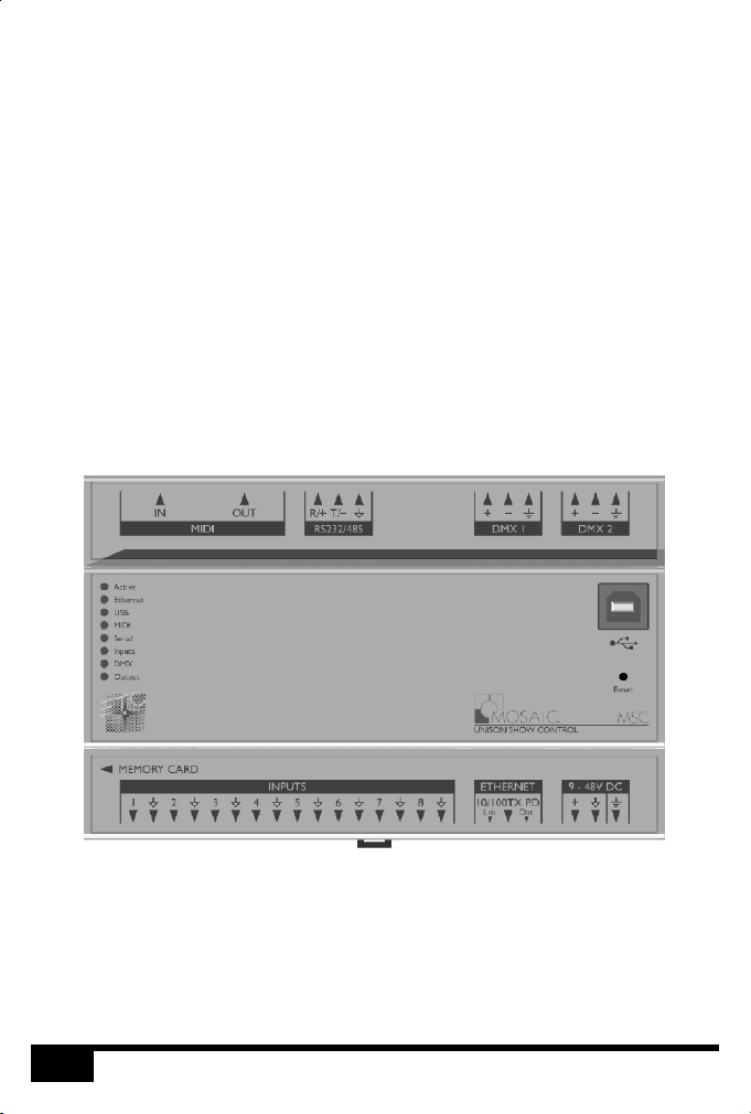
MSC LAYOUT
The following drawing illustrates the layout of the Unison Mosaic Show Controller, refer to the
following sections for details:
STATUS
LEDS
RS232/485 SERIALMIDI INPUT & OUTPUT
DIGITAL INPUTS (8)
DMX512 OUTPUTS (2)
ETHERNET
(PoE)
DC INPUT
(9-48V)
USB
RESET
MSC VERSIONS
There are three versions of the MSC available: MSC 1, MSC 2 and MSC 4. The MSC 1 supports
512 DMX channels, the MSC 2 supports 1024 channels and the MSC 4 supports 2048 channels
(of which 1024 channels are eDMX only). All can be used as a stand-alone controller or cooperatively, via an Ethernet network, to form a scalable system.
MSC
6
Page 7

POWER SUPPLY
The MSC can be powered in two different ways:
• DC power (9 to 48V)
A limited power source approved to UL60950-1 2 Edition, CAN/CSA C22.2 No. 60950-
nd
1.07 2 Edition MUST be used, with an output voltage of 9 to 48V DC.
nd
Such a power supply can be connected directly to the MSC using the DC Input connector.
The pins on this connector are marked:
Positive input (9 to 48V DC)
Signal ground (0V)
Chassis ground (earth)
The power supply should be connected to the Positive and Signal ground inputs, ensuring
the polarity is correct. Where possible, use a 12V (minimum) supply in preference to a 9V
supply to ensure some headroom.
The MSC will typically consume 4W.
• Power-over-Ethernet (PoE)
A standard (802.3af) Power-over-Ethernet switch may be used to provide both power and
a network connection to the MSC using a single cable.
The MSC operates as a PoE Class 2 device (3.84>6.49W) and will typically consume 4W.
NOTE: Power should only be applied using one of the above methods. Redundant
operation using both sources is not supported.
NOTE: Power must not be disconnected when uploading project data nor during
bootloader/firmware updates to the MSC as corruption of the data or
software may occur, perhaps even rendering the unit inoperable.
GROUNDING
The MSC is designed to be mounted on a grounded (earthed) DIN-rail and a dedicated Chassis
ground (earth) terminal is also provided which should be connected to a suitable earth.
Additionally, the Signal ground can be tied to Chassis ground to provide a suitable reference but
this is not generally recommended.
If in any doubt at all, or if you have unusual power supply or grounding/earthing requirements,
then please consult ETC support.
7
MSC
Page 8

REALTIME CLOCK BATTERY
The MSC’s internal realtime clock is battery-backed to ensure operation when the unit is not
powered. The battery should last for at least 10 years and is easily replaced when necessary,
replacement battery: Renata CR2032 Lithium Button Cell.
CAUTION: Risk of explosion if battery replaced by incorrect type. Dispose of used
ATTENTION: Il y a un danger d’explosion s’il y a un remplacement incorrect de batterie.
MEMORY CARD
The MSC is shipped with a 256Mbyte SD Memory Card which should be sufficient for most
projects since the MSC’s data storage is extremely efficient, even with a multitude of imported
media files. However, a larger capacity card could of course be fitted if required.
As only the project’s programming data resides on the card, the card is also a convenient way to
backup data for archiving; the Designer project file for example.
Furthermore, in the event of MSC hardware failure, simply moving the card into a replacement
unit with identical or more recent firmware is sufficient to get the project up and running again.
STATUS LEDS
The ETC logo will illuminate when power is applied to the MSC. The red LEDs on the front of
the MSC indicate the unit’s current status.
The Active LED illuminates once the boot up procedure has completed and is indicative of a
fully functional unit.
The Ethernet LED indicates Mosaic-related network activity (not network link, see Ethernet
port later) while the remaining LEDs indicate communication on the various ports of the MSC.
The Output LED indicates that a valid project file has been loaded from the memory card and
that playback & data output has started.
batteries according to the manufacturer’s instructions.
Mettre au rebut les batteries usages conformement aux instructions du
fabricant.
The DMX LED indicates that valid DMX512 data is being output from the DMX ports.
ERROR CODES
Additionally the red status LEDs are used to indicate any boot failures of the MSC that prevent
the unit from going active. These codes are outlined below and in all cases the Active LED will
be off.
MSC
8
Page 9

• Ethernet & USB double flashing - failed to boot firmware (follow the MSC recovery
procedure detailed in Designer Help)
• Ethernet, MIDI & USB triple flashing - memory card missing (insert or replace card)
RESET SWITCH
The MSC may be reset by inserting a small blunt object into the reset hole on the front of the
MSC to depress the reset switch. The switch should be held for at least one second.
NOTE: The reset must not be operated when uploading project data nor during
WATCHDOG
The internal “watchdog” is enabled by default to reset automatically the MSC in case of a
software crash as a result of either a coding error (“bug”) or a random electromagnetic event
such as a power brown-out or spike, nearby lightning strike or static discharge. Please refer to
the Designer Help to learn how to disable this feature (not recommended).
bootloader/firmware updates to the MSC as corruption of the data or
software may occur, perhaps even rendering the unit inoperable.
9
MSC
Page 10

PORTS
• RS232/RS485 Serial Port
The serial port's protocol (RS232 or RS485), data rate and format settings (baud, parity,
stop bits, etc.) are configured using Designer.
In RS232 mode, the port operates in full duplex with the following pinout:
Receive
R/+
Transmit
T/-
Signal ground
In RS485 (and DMX In) mode, the port operates in half duplex with the following pinout:
Data +
R/+
Data -
T/-
Signal ground
The serial port is not isolated from the MSC’s power supply. If isolation is required, it must
either be provided by the connected device or a separate isolator should be used.
• MIDI Input and Output
The MIDI input and output connectors are standard 5 pin DIN connections. They may be
connected directly to any standard MIDI device.
• DMX Outputs
Two DMX outputs are provided. An MSC 1 will output on both the same DMX universe
data, an MSC 2 will output a separate universe on each. The pins on these connectors are
marked:
Data + (‘Hot’ or ‘True’)
Data - (‘Cold’ or ‘Complement’)
Chassis ground (shield)
To make up a cable to a 5 pin XLR the following connections should be made:
Data + 3
Data - 2
Shield 1
MSC
MSC: 5 pin XLR:
10
Page 11

The DMX ports are by default not isolated from the MSC’s ground connection which is
the recommended configuration for driving isolated inputs - the majority of DMX
receivers.
If required this may be changed by removing the top cover of the MSC and removing the
jumper marked ‘JP1’, located to the right of the DMX ports. The two DMX ports will then
be optically isolated from the MSC’s internal circuitry although not from each other.
• Digital/Analog Inputs
The MSC features 8 digital/analog inputs on one 16 way connector. To connect an input
signal to the MSC, one connection should be made to the desired input pin, marked '1' to
'8', and the other should be made to the adjacent signal ground pin.
The inputs can be individually configured via Designer to operate in one of three modes:
Contact closure: An external volt-free switch may be connected between the input pin
and the signal ground pin.
In this mode, the input pin is internally pulled-up to 5V via a 2.2Kohm resistor, so the
switch only needs to be rated at 5V, 2.5mA or greater.
Digital input: An external voltage source (such as a 12V trigger output) may be
connected between the input pin and the signal ground pin.
In this mode, the input pin is internally pulled down to 0V via a 2Mohm resistor and the
maximum input voltage supported is 24V.
The MSC may be configured to specify what the 'high' and 'low' threshold voltages are. This
facility can be used to provide 'Schmitt trigger' action.
Analog input: An external voltage source (such as a 0-10V analog signal) may be
connected between the input pin and the signal ground pin.
In this mode, the input pin is internally pulled down to 0V via a 2Mohm resistor and the
maximum input voltage supported is 24V.
The MSC may be configured to specify what the input voltage range is. Voltages inside this
range are reported as 0% to 100%.
In all modes, the maximum rated input voltage is 24V. The inputs should never be driven
with a higher voltage nor negative voltage or damage may occur.
In all modes, all signal ground pins are connected together internally. The digital/analog
inputs are not isolated from each other nor the MSC’s power supply. If isolation is
required, it must either be provided by the connected device or a separate isolator should
be used.
11
MSC
Page 12

• Ethernet
A standard 10/100TX Ethernet connection may be made to the MSC. As the MSC
supports Power-over-Ethernet (PoE), a PoE switch or midspan injector can be used. The
LEDs on the RJ45 jack itself are useful for debugging the Ethernet installation:
The Lnk LED will illuminate when an Ethernet link has been established.
The Dat LED will illuminate to indicate Ethernet traffic (not just Mosaic-relevant).
• USB
The USB port may be used to connect the MSC to a PC to upload project data and update
the MSC’s internal operating software.
NOTE: Ports and third party equipment can be damaged when plugging or
unplugging an energised system (hot-plugging). It is therefore advisable to
remove power before making or breaking port connections.
MSC
12
Page 13

13
MSC
Page 14
TPC INSTALLATION
The Mosaic Tessera Panel Controller (TPC) is a fully fledged Controller in its own right with an
integrated touch screen user interface. It can also share its user interface with other Mosaic
Controllers when operating as part of a system across an Ethernet network.
The units are designed to be permanently installed into UK double-gang or custom back boxes
(supplied separately). The units are 100% solid state and have been qualified to operate in a dry
environment within a temperature range of 0°C to 50°C (32°F to 122°F).
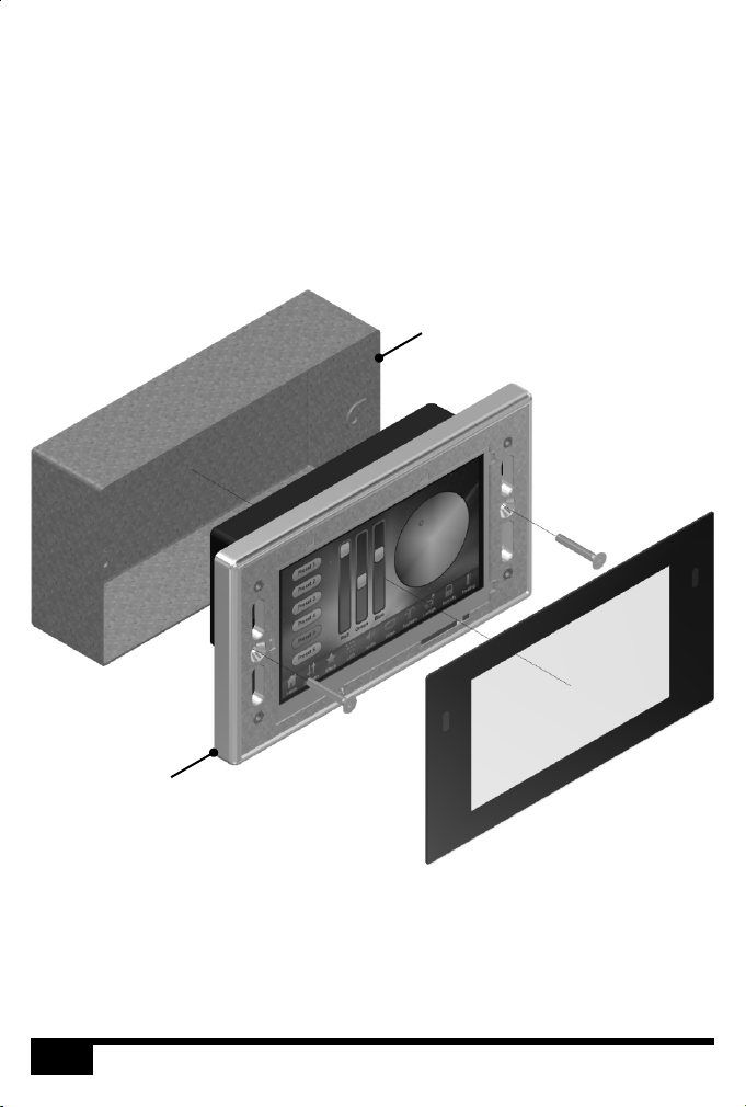
The following drawing illustrates a typical installation:
BACK BOX: 35mm (1.5”) or deeper, remove or
bend flat the top and bottom tabs if present
BEZEL & ELECTRONICS: Mounts flush to the wall,
ensure that the back box cutout is not oversized
Carefully remove the protective films from the front of the liquid crystal display and the
magnetic overlay before final assembly.
TPC LAYOUT
The following drawing illustrates the layout of a Mosaic Tessera Panel Controller (shown with
overlay removed), refer to the following sections for details:
TPC
14
Page 15
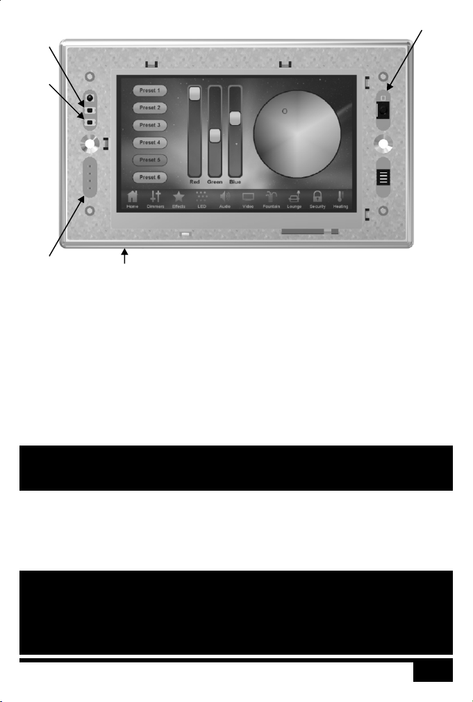
RESET
CONFIG
STATUS
LEDS
SD CARD
POWER SUPPLY
• Power-over-Ethernet (PoE)
A standard (802.3af) Power-over-Ethernet switch should be used to provide both power
and a network connection to the TPC using a single cable. Alternatively, if a PoE switch is
not available, a PoE midspan injector could be used.
A limited power source approved to UL60950-1 2 Edition, CAN/CSA C22.2 No. 60950-
nd
1.07 2 Edition MUST be used, with an SELV output voltage.
nd
SENSORS
The TPC operates as a PoE Class 2 device (3.84>6.49W) and will typically consume 4W.
NOTE: Power must not be disconnected during firmware updates to the TPC as
corruption of the software may occur, perhaps even rendering the unit
inoperable.
REALTIME CLOCK BATTERY
The TPC’s internal realtime clock is battery-backed to ensure operation when the unit is not
powered. The battery should last for at least 10 years and is easily replaced when necessary,
replacement battery: Renata CR2032 Lithium Button Cell.
CAUTION: Risk of explosion if battery replaced by incorrect type. Dispose of used
batteries according to the manufacturer’s instructions.
ATTENTION: Il y a un danger d’explosion s’il y a un remplacement incorrect de batterie.
Mettre au rebut les batteries usages conformement aux instructions du
fabricant.
15
TPC
Page 16

MEMORY CARD
The TPC is shipped with a 256Mbyte SD Memory Card which should be sufficient for most
projects since the TPC’s data storage is extremely efficient, even with a multitude of imported
media files. However, a larger capacity card could of course be fitted if required.
As only the project’s programming data resides on the card, the card is also a convenient way to
backup data for archiving; the Designer project file for example.
Furthermore, in the event of TPC hardware failure, simply moving the card into a replacement
unit with identical or more recent firmware is sufficient to get the project up and running again.
STATUS LEDS
The LEDs on the rear of the unit provide the following status information:
Pwr: Power - illuminates when the unit is correctly powered.
Act: Active - illuminates once the boot up procedure has completed and is indicative of a
Net: Network - illuminates when the unit is sending or receiving Mosaic-related data.
Lnk: Link - illuminates once the unit has established an Ethernet link.
100: 100BASE-TX - illuminates when the Ethernet link is operating at 100Mbit/s.
The LEDs on the front of the unit (under the overlay) provide the following status information:
Pwr: Power - illuminates when the unit is correctly powered.
Act: Active - illuminates once the boot up procedure has completed and is indicative of a
Eth: Ethernet - illuminates when the unit is sending or receiving Mosaic-related data.
Out: Output - indicates that a valid project file has been loaded from the memory card
fully functional unit.
fully functional unit.
and that playback & data output has started.
ERROR CODES
Additionally the red status LEDs are used to indicate any boot failures of the TPC that prevent
the unit from going active. These codes are outlined below and in all cases the Active LED will
be off.
• Ethernet & Output double flashing - failed to boot firmware (follow the TPC recovery
procedure detailed in Designer Help)
• Ethernet & Output triple flashing - memory card missing (insert or replace card)
TPC
16
Page 17

RESET SWITCH
The TPC may be reset by removing the magnetic overlay and pressing the reset switch. The
switch should be held for at least one second.
NOTE: The reset must not be operated during firmware updates to the TPC as
CONFIG SWITCH
The TPC may be placed in a configuration mode by removing the magnetic overlay and pressing
the config switch, refer to Designer Help for instructions.
WATCHDOG
An internal "watchdog" will automatically reset the TPC in case of a software crash as a result
of either a coding error ("bug") or a random electromagnetic event such as a power brown-out
or spike, nearby lightning strike or static discharge.
LEARNING IR RECEIVER
The TPC may be taught to recognise different IR codes from a standard infra red remote
control, refer to Designer Help for instructions.
corruption of the software may occur, perhaps even rendering the unit
inoperable.
17
TPC
Page 18

MSC X INSTALLATION
Unison Mosaic MSC X
The is designed to be rack mounted in a central control room for fixed
installations or flight cased for touring applications. The 2U enclosure and 19” rack mounting
complies with IEC 60297.
The unit is largely solid state and has been qualified to operate in a dry environment within a
temperature range of 0°C to 50°C (32°F to 122°F).
NOTE: Particular attention must be paid to cooling; under no circumstances should
the airflow to the heat sinks be restricted and a rack fan cooling unit should
be considered when multiple units are stacked together to maintain the
correct ambient temperature.
Since the unit requires no user intervention once installed it is suitable for remote installation
with all configuration and management taking place over an Ethernet network. However it is
recommended that access can be gained in the unlikely event of a hardware failure.
MSC X LAYOUT
The following drawings illustrate the layout of the MSC X, refer to the following sections for
details:
FRONT
CF CARD
(BEHIND PANEL)
BACK
RTC BATTERY
(BEHIND PANEL)
MSC X VERSIONS
There are multiple versions of the MSC X that differ only in the maximum number of control
channels that can be accommodated. For example, the MSC 20 can control 20 DMX universes
(10,240 channels) while the MSC 200 can control 200 DMX universes (102,400 channels).
The MSC X can be used as a stand-alone controller or co-operatively with other Unison
Mosaic Controllers and Remote Devices, via an Ethernet network, to form a scalable system.
X
18
Page 19

POWER SUPPLY
The MSC X is mains powered via a fused, universal input power supply unit (PSU) compatible
with all worldwide mains supply standards; 100-250V 50/60Hz. The replacement fuse should be
a 250V rated 1A T (anti-surge) 20mm cartridge type only.
The MSC X will typically consume a maximum of 50-75W (MSC 200 @ 110-240V).
NOTE: Power must not be disconnected when uploading project data nor during
UK, EU and US mains IEC cables are provided.
CAUTION: For pluggable equipment, the socket outlet shall be installed near the
ATTENTION: En cas d'équipement enfichable, la prise doit être montée près de
GROUNDING
The MSC X must be correctly grounded to electrical safety earth at all times.
REALTIME CLOCK BATTERIES
The MSC X’s internal realtime clock is battery-backed to ensure operation when the unit is not
powered. The batteries should last for at least 10 years and are easily replaced when necessary,
replacement battery: Renata CR2032 Lithium Button Cell.
CAUTION: Risk of explosion if battery replaced by incorrect type. Dispose of used
ATTENTION: Il y a un danger d’explosion s’il y a un remplacement incorrect de batterie.
MEMORY CARD
The MSC X is shipped with a 4Gbyte Type I Compact Flash card which should be sufficient for
most projects since the MSC X’s data storage is extremely efficient, even with a multitude of
imported media files. However, a larger capacity card could of course be fitted if required.
bootloader/firmware updates to the MSC X as corruption of the data or
software may occur, perhaps even rendering the unit inoperable.
equipment and shall be easily accessible.
l'équipement et doit offrir un accès facile.
batteries according to the manufacturer’s instructions.
Mettre au rebut les batteries usages conformement aux instructions du
fabricant.
As only the project’s programming data resides on the card, the card is also a convenient way to
backup data for archiving; the Designer project file for example.
Furthermore, in the event of MSC X hardware failure, simply moving the card into a
replacement unit is sufficient to get the project up and running again.
19
X
Page 20

STATUS LEDS
The ETC logo will illuminate when power is applied to the MSC X. The red LEDs above
indicate the unit’s current status.
The Active LED flashes throughout the boot up procedure and lights solidly once this has been
completed and is indicative of a fully functional unit.
The Ethernet LEDs indicates Mosaic-related network activity (not network link) while other
LEDs indicate communication on the various ports of the MSC X.
The Output LED indicates that a valid project file has been loaded from the memory card and
that playback & data output (eDMX & DVI) has started.
The Overtemp LED will illuminate if the processor core(s) reaches 95°C (203°F) indicating a
fault in the system’s cooling, typically caused by raised ambient temperatures. Consult the web
interface’s home page to monitor the system temperatures and take remedial action.
ERROR CODES
Additionally the red status LEDs are used to indicate any boot failures of the MSC X that
prevent the unit from going active. Error codes are displayed by a repeating pattern of flashing
LEDs a number of times in succession, followed by a 1 second pause.
• Front panel LED codes (all LEDs):
1 flash - Invalid build version
2 flashes - Unable to determine serial number
3 flashes - SPI flash test failed
4 flashes - Unable to perform front panel factory restore as factory firmware is corrupt
5 flashes - Current firmware is corrupt, no valid firmware versions available to restore
6 flashes - Restored front panel firmware is corrupt
• Main board LED codes (bottom 4 LEDs):
2 flashes - Failed to power up main board
3 flashes - Firmware failed to boot
4 flashes - Power failed during boot
5 flashes - Power failed during normal operation
6 flashes - Watchdog timeout expired
Main board errors can usually be resolved by removing the Compact Flash card and running
the MSC X Recovery Tool on a PC to format the card and reinstall the firmware. All
project data will be erased and so an upload will be required to restore programming.
RESET SWITCH
The MSC X may be reset by inserting a small blunt object into the reset hole on the front panel
to depress the reset switch. The switch should be held for at least one second.
X
20
Page 21

NOTE: The reset must not be operated when uploading project data nor during
WATCHDOG
The internal “watchdog” is enabled by default to reset automatically the MSC X in case of a
software crash as a result of either a coding error (“bug”) or a random electromagnetic event
such as a power brown-out or spike, nearby lightning strike or static discharge. Please refer to
the Designer Help to learn how to disable this feature (not recommended).
PORTS
• Ethernet 1 - Management
A standard 10/100/1000BASE-T Ethernet connection may be made to this port for
management and networking to other Unison Mosaic Controllers and Remote Devices.
• Ethernet 2 - Protocol
A standard 10/100/1000BASE-T Ethernet connection may be made to this port to output
data to lighting fixtures using Ethernet protocols (eDMX) such as sACN, ArtNet & KiNet.
• DVI-I Output
A standard DVI connection may be made to this port to route output data to the lighting
fixtures using the Digital Video Interface.
• RS232 Serial Ports (2)
The serial ports may be connected directly to a PC using a null modem cable. Other
devices may require different cables depending on their pinout. The serial port is a 9 pin
male D connector with the following pinout:
bootloader/firmware updates to the MSC X as corruption of the data or
software may occur, perhaps even rendering the unit inoperable.
1: DCD
2: Receive data (RXD)
3: Transmit data (TXD)
4: DTR
5: Signal ground
6: DSR
7: RTS
8: CTS
9: RI
The serial port is not isolated from the MSC X’s power supply. If isolation is required, it
must either be provided by the connected device or a separate isolator should be used.
21
X
Page 22

• DMX Input
A USITT DMX 512 compatible input is provided on a standard 5 pin male XLR connector
with the following pinout:
1: Shield
2: Data - (‘Cold’ or ‘Complement’)
3: Data + (‘Hot’ or ‘True’)
4-5: Not connected
The DMX input port is optically isolated from the MSC X’s electronics and ground
connection which is the recommended configuration for a DMX receiver.
• IEEE 1394 (2)
Port 1 supports standard IEEE 1394 (aka Firewire) and may be used to connect a Digital
Video (DV) input source, for example a camera for live input.
Port 2 is not supported at the time of writing (refer to the current Designer Help).
• USB 2.0 Host
This port is not supported at the time of writing (refer to the current Designer Help).
NOTE: Ports and third party equipment can be damaged when plugging or
unplugging an energised system (hot-plugging). It is therefore advisable to
remove power before making or breaking port connections.
22X23X24
Page 23

Page 24

AVC INSTALLATION
Unison Mosaic
The Audio Visual Controller (AVC) is designed to be permanently installed in a
central control room/cupboard or DIN consumer unit for remote deployment. The enclosure
and mounting complies with DIN43880 and EN60715 (35/7.5 rail) respectively.
The unit is 100% solid state and has been qualified to operate in a dry environment within a
temperature range of 0°C to 50°C (32°F to 122°F). Sealed IP65 rated consumer units are
available for outdoor use, please consult your ETC distributor or representative.
Since the unit requires no user intervention once installed it is suitable for remote installation
with all configuration and management taking place over an Ethernet network. However it is
recommended that access can be gained in the unlikely event of a hardware failure.
AVC LAYOUT
The following drawing illustrates the layout of the Unison Mosaic Audio Visual Controller, refer
to the following sections for details:
AUDIO/VIDEO OUTPUTS
RS232/485 PORT
STATUS
LEDS
AVC
AUDIO/VIDEO INPUTS
ETHERNET
DC INPUT
(9-48V)
USB
RESET
Page 25

POWER SUPPLY
• DC power (9 to 48V)
A limited power source approved to UL60950-1 2 Edition, CAN/CSA C22.2 No. 60950-
nd
1.07 2 Edition MUST be used, with an output voltage of 9 to 48V DC.
nd
Such a power supply can be connected directly to the AVC using the DC Input connector.
The pins on this connector are marked:
Positive input (9 to 48V DC)
Signal ground (0V)
Chassis ground (earth)
The power supply should be connected to the Positive and Signal ground inputs, ensuring
the polarity is correct. Where possible, use a 12V (minimum) supply in preference to a 9V
supply to ensure some headroom.
The AVC will typically consume 7W.
NOTE: Power must not be disconnected when uploading project data nor during
bootloader/firmware updates to the AVC as corruption of the data or
software may occur, perhaps even rendering the unit inoperable.
GROUNDING
The AVC is designed to be mounted on a grounded (earthed) DIN-rail and a dedicated Chassis
ground (earth) terminal is also provided which should be connected to a suitable earth.
Additionally, the Signal ground can be tied to Chassis ground to provide a suitable reference but
this is not generally recommended.
If in any doubt at all, or if you have unusual power supply or grounding/earthing requirements,
then please consult ETC support.
25
AVC
Page 26

REALTIME CLOCK BATTERY
The AVC’s internal realtime clock is battery-backed to ensure operation when the unit is not
powered. The battery should last for at least 10 years and is easily replaced when necessary,
replacement battery: Renata CR2032 Lithium Button Cell.
CAUTION: Risk of explosion if battery replaced by incorrect type. Dispose of used
ATTENTION: Il y a un danger d’explosion s’il y a un remplacement incorrect de batterie.
MEMORY CARD
The AVC is shipped with a 4Gbyte Type I Compact Flash card.
The duration of video content that can be stored on a card will vary depending on the MPEG2
bitrate used to encode it. For a 4GB card, capacity could be anything from 60 to 180 minutes.
However, a larger capacity card could of course be fitted if required.
As only the project’s programming data resides on the card, the card is also a convenient way to
backup data for archiving; the Designer project file for example.
Furthermore, in the event of AVC hardware failure, simply moving the card into a replacement
unit with identical or more recent firmware is sufficient to get the project up and running again.
STATUS LEDS
The ETC logo will illuminate when power is applied to the AVC. The red LEDs on the front of
the AVC indicate the unit’s current status.
The Active LED illuminates once the boot up procedure has completed and is indicative of a
fully functional unit.
The Ethernet LED indicates Mosaic-related network activity (not network link) while the
remaining LEDs indicate communication on the various ports of the AVC.
batteries according to the manufacturer’s instructions.
Mettre au rebut les batteries usages conformement aux instructions du
fabricant.
Either the PAL or NTSC LED will illuminate once a valid project file has been loaded from the
memory card and playback & video output has started. The choice of LED will indicate which
video system is being used, this having been configured using the Designer software.
ERROR CODES
Additionally the red status LEDs are used to indicate any boot failures of the AVC that prevent
the unit from going active. These codes are outlined below and in all cases the Active LED will
be off.
AVC
26
Page 27

• Bootloader LED codes:
Ethernet & USB double flashing - failed to boot firmware (use the AVC Firmware Updater
to repair)
NTSC & PAL solid + Ethernet/USB indicating activity - erasing flash (not an error, will
occur when updating firmware)
NTSC & PAL flashing + Ethernet/USB indicating activity - programming flash (not an error,
will occur when updating firmware)
• Firmware LED codes:
Ethernet & USB double flashing + Serial solid - CF card missing (insert or replace the card)
RESET SWITCH
The AVC may be reset by inserting a small blunt object into the reset hole on the front of the
AVC to depress the reset switch. The switch should be held for at least one second.
NOTE: The reset must not be operated when uploading project data nor during
WATCHDOG
The internal “watchdog” is enabled by default to reset automatically the AVC in case of a
software crash as a result of either a coding error (“bug”) or a random electromagnetic event
such as a power brown-out or spike, nearby lightning strike or static discharge. Please refer to
the Designer Help to learn how to disable this feature (not recommended).
VIDEO SYSTEMS
The AVC supports either the NTSC (525/60) or PAL (625/50) video systems and this
configuration is done using the Designer software and is uploaded as part of the project file.
Video coding: MPEG-2 MP@ML/SP@ML VBR/CBR
Coded frame rate: 29.97fps (525/60, interlaced)
Display frame rate: 29.97fps (525/60, interlaced)
MPEG-2 resolution: 720x480 & 704x480 (525/60)
MPEG-2 GOP max: 36fields/18frames (525/60), 30/15 recommended
Aspect ratio: 4:3 or 16:9 anamorphic
bootloader/firmware updates to the AVC as corruption of the data or
software may occur, perhaps even rendering the unit inoperable
25fps (625/50, interlaced)
25fps (625/50, interlaced)
720x576 & 704x576 (625/50)
30fields/15frames (625/50), 24/12 recommended
27
AVC
Page 28

PORTS
• Video Output
Video output is via three BNC connectors. These connectors can be configured using
Designer to output either Composite (CV), S-Video (Y, C) or Component (Y, Pr, Pb).
The video output is taken from the output of an internal video mixer, the inputs to which
are the encoded video (uploaded using Designer) and the video input.
• Analog Audio Output
Balanced stereo audio output is provided @ 0dBV line level on a 6 way connector:
Balanced audio right channel +
R
Balanced audio right channel - (tie to ground for unbalanced)
Signal ground
Balanced audio left channel +
L
Balanced audio left channel - (tie to ground for unbalanced)
Signal ground
The analog audio output is taken from the output of an internal audio mixer, the inputs to
which are the encoded stereo audio (uploaded using Designer) and the analog audio input.
• Digital Audio Output
This port is not supported at the time of writing (refer to the current Designer Help).
• Video Input
Video input is via two BNC connectors. These connectors can be configured using
Designer to accept either Composite (CV) or S-Video (Y, C).
• Analog Audio Input
Balanced stereo audio input is provided @ 0dBV line level on a 6 way connector:
Balanced audio right channel +
R
Balanced audio right channel - (tie to ground for unbalanced)
Signal ground
Balanced audio left channel +
L
Balanced audio left channel - (tie to ground for unbalanced)
Signal ground
AVC
28
Page 29

• RS232/RS485 Serial Port
The serial port's protocol (RS232 or RS485), data rate and format settings (baud, parity,
stop bits, etc.) are configured using Designer.
In RS232 mode, the port operates in full duplex with the following pinout:
Receive
R/+
Transmit
T/-
Signal ground
In RS485 (and DMX In) mode, the port operates in half duplex with the following pinout:
Data +
R/+
Data -
T/-
Signal ground
The serial port is not isolated from the AVC’s power supply. If isolation is required, it must
either be provided by the connected device or a separate RS232 isolator should be used.
• Ethernet
A standard 10/100TX Ethernet connection may be made to the AVC.
• USB
The USB port may be used to connect the AVC to a PC to upload project data (excluding
audio/video content) and update the AVC’s internal operating software.
NOTE: Ports and third party equipment can be damaged when plugging or
unplugging an energised system (hot-plugging). It is therefore advisable to
remove power before making or breaking port connections.
29
AVC
Page 30

RIO INSTALLATION
The Unison Mosaic Remote Input/Output Devices (RIO) are ancillary devices that provide
additional input and output interfaces to a system. As such, they can not be used on their own
but must have at least one Controller present on an Ethernet network to function.
The units are designed to be permanently installed in a control room/cupboard or DIN
consumer unit. The enclosure and mounting complies with DIN43880 and EN60715 (35/7.5
rail) respectively.
The units are 100% solid state and have been qualified to operate in a dry environment within a
temperature range of 0°C to 50°C (32°F to 122°F). Sealed IP65 rated consumer units are
available for outdoor use, please consult your ETC distributor or representative.
RIO LAYOUT
The following drawing illustrates the layout of a Unison Mosaic Remote Input/Output Device,
refer to the following sections for details:
IO PORTS
RIO VERSIONS
STATUS
LEDS
IO PORTS
ETHERNET
(PoE)
ADDRESS
WHEEL
RESET
There are four versions of the RIO available:
RIO 80: 8 digital/analog inputs & RS232/485/DMX serial port.
RIO 44: 4 digital/analog inputs, 4 relay outputs & RS232/485/DMX serial port (shown above).
RIO 08: 8 relay outputs & RS232/485/DMX serial port.
RIO-A: Balanced stereo audio/timecode input & MIDI input/output ports.
RIO
30
Page 31

POWER SUPPLY
• Power-over-Ethernet (PoE)
A standard (802.3af) Power-over-Ethernet switch should be used to provide both power
and a network connection to the RIO using a single cable. Alternatively, if a PoE switch is
not available, a PoE midspan injector could be used.
The RIO operates as a PoE Class 1 device (0.44>3.84W) and will typically consume 1.5W.
NOTE: Power must not be disconnected during firmware updates to the RIO as
GROUNDING
The RIO is designed to be mounted on a grounded (earthed) DIN-rail, no dedicated Chassis
ground (earth) terminal is provided.
The PoE connection (power and data) is completely isolated from all the RIO’s ports but the
ports are not isolated from each other (except relay outputs, RIO 44 and RIO 08 only).
STATUS LEDS
The ETC logo will illuminate when power is applied to the RIO. The red LEDs on the front of
the RIO indicate the unit's current status.
The Active LED flashes slowly once the boot up procedure has completed to indicate a fully
functional unit. Once the RIO has connected to a project running on a Controller, the Active
LED will light continuously.
The Ethernet LED indicates Mosaic-related network activity (not network link, see Ethernet
port later) while the remaining LEDs indicate communication on the various ports of the RIO.
ERROR CODES
Additionally the red status LEDs are used to indicate any boot failures of the RIO that prevent
the unit from operating. Error codes are displayed by a repeating pattern of flashing all four
LEDs a number of times in succession, followed by a 1 second pause:
1 flash - Invalid firmware version (reload firmware from Designer)
2 flashes - Invalid device type or serial number
3 flashes - Internal memory test error
4 flashes - Unable to perform factory restore due to corrupt factory firmware
5 flashes - Current firmware is corrupt, no valid firmware versions available to restore
6 flashes - Restored firmware is corrupt
corruption of the software may occur, perhaps even rendering the unit
inoperable.
Codes 2 through 6 indicate a hardware error; please consult your distributor, representative or
ETC support for assistance.
31
RIO
Page 32

ADDRESS WHEEL
Multiple RIOs may be used on a single network. Each RIO is uniquely identified by its type (80,
44, 08 or A) and an address setting.
Wheel settings '1' to '15' directly set the RIO's address to the corresponding number. Up to 15
of each type may be addressed in this way. For systems with more than 15 RIOs of a single
type, the manual ('M') setting should be used to allow identification using the RIO's serial
number rather than the address.
RESET SWITCH
The RIO may be reset by inserting a small blunt object into the reset hole on the front of the
RIO to depress the reset switch. The switch should be held for at least one second.
NOTE: The reset must not be operated during firmware updates to the RIO as
WATCHDOG
An internal "watchdog" will automatically reset the RIO in case of a software crash as a result of
either a coding error ("bug") or a random electromagnetic event such as a power brown-out or
spike, nearby lightning strike or static discharge.
PORTS
• Digital/Analog Inputs (RIO 80 and RIO 44 only)
The RIO features 8 (RIO 80) or 4 (RIO 44) digital/analog inputs on two (RIO 80) or one
(RIO 44) 8 way connectors. To connect an input signal to the RIO, one connection should
be made to the desired input pin, marked '1' to '8' (RIO 80) or '1' to '4' (RIO 44), and the
other should be made to the adjacent common pin.
The RIO inputs can be individually configured to operate in one of three modes:
Contact closure: An external volt-free switch may be connected between the input pin
and the signal ground pin.
In this mode, the input pin is internally pulled-up to 5V via a 2.2Kohm resistor, so the
switch only needs to be rated at 5V, 2.5mA or greater.
Digital input: An external voltage source (such as a 12V trigger output) may be
connected between the input pin and the signal ground pin.
In this mode, the input pin is internally pulled down to 0V via a 2Mohm resistor and the
maximum input voltage supported is 24V.
corruption of the software may occur, perhaps even rendering the unit
inoperable.
RIO
32
Page 33

The RIO may be configured using Designer to specify what the 'high' and 'low' threshold
voltages are. This facility can be used to provide 'Schmitt trigger' action.
Analog input: An external voltage source (such as a 0-10V analog signal) may be
connected between the input pin and the signal ground pin.
In this mode, the input pin is internally pulled down to 0V via a 2Mohm resistor and the
maximum input voltage supported is 24V.
The RIO may be configured using Designer to specify what the input voltage range is.
Voltages inside this range are reported as 0% to 100%.
In all modes, the maximum rated input voltage is 24V. The inputs should never be driven
with a higher voltage nor negative voltage or damage may occur.
• Relay Outputs (RIO 08 and RIO 44 only)
The RIO features 8 (RIO 08) or 4 (RIO 44) relay outputs on two (RIO 08) or one (RIO 44)
8 way connectors.
The RIO relays are rated at 48V, 0.25A. This comparatively low rating is due to the use of
solid-state relays to ensure silent operation and long-term reliability.
All relay outputs are fully isolated from each other and all other ports.
• RS232/RS485/DMX Serial Port (RIO 80, RIO 44 and RIO 08 only)
The serial port's protocol (RS232 or RS485), data rate and format settings (baud, parity,
stop bits, etc.) are configured using Designer. The port can additionally be configured to
output 96 channels of DMX512 control data (RDM is not supported).
In RS232 mode, the port operates in full duplex with the following pinout:
Receive
R/+
Transmit
T/-
Signal ground
In RS485 & DMX modes, the port operates in half duplex with the following pinout:
Data +
R/+
Data -
T/-
Signal ground
• MIDI Input and Output (RIO-A only)
The MIDI input and output connectors are standard 5 pin DIN connections. They may be
connected directly to any standard MIDI device.
33
RIO
Page 34

• Analog Audio Input (RIO-A only)
Balanced stereo audio input is provided @ 0dBV line level on a 6 way connector:
Balanced audio right channel +
R
Balanced audio right channel - (tie to ground for unbalanced)
Signal ground
Balanced audio left channel +
L
Balanced audio left channel - (tie to ground for unbalanced)
Signal ground
The audio input can also accept linear time code (LTC) such as SMPTE/EBU on either
channel but not both, configured using Designer. The Audio / LTC LED will indicate peak
for audio and valid for time code.
• DALI (RIO D only)
A DALI bus interface is provided on a 3 way connector:
DALI bus (polarity insensitive)
DALI bus (polarity insensitive)
Chassis ground (for optional shield)
The interface can be configured using Designer as either a Master for controlling up to 64
DALI ballasts or a Slave for triggering by third-party controllers using the DALI protocol.
The DALI data LED will indicate valid data on the bus.
NOTE: The DALI bus requires a dedicated DALI bus power supply to function, the
DALI power LED will illuminate solidly to indicate suitable (9-26V) power.
The LED will be off for no power or flash to indicate out of range power.
• Ethernet
A standard 10/100TX Ethernet connection must be made to the RIO. A Power-overEthernet (PoE) switch or midspan injector is required to operate the RIO. The LEDs on
the RJ45 jack itself are useful for debugging the Ethernet installation:
The Lnk LED will illuminate when an Ethernet link has been established.
The Dat LED will illuminate to indicate Ethernet traffic (not just Mosaic-relevant).
NOTE: Ports and third party equipment can be damaged when plugging or
unplugging an energised system (hot-plugging). It is therefore advisable to
remove power before making or breaking port connections.
RIO
34
Page 35

35
RIO
Page 36

BPS INSTALLATION
The Unsion Mosaic Button Panel Stations (BPS) are ancillary devices that provide user
interfaces to a system. As such, they can not be used on their own but must have at least one
Controller present on an Ethernet network to function.
The units are designed to be permanently installed into UK or US single-gang back boxes
(supplied separately). The units are 100% solid state and have been qualified to operate in a dry
environment within a temperature range of 0°C to 50°C (32°F to 122°F).
The following drawing illustrates a typical installation (M108-6-EU shown):
BACK BOX: 35mm (1.5”) or deeper, remove or
bend flat the top and bottom tabs if present
BEZEL & ELECTRONICS: Mounts flush to the wall,
ensure that the back box cutout is not oversized
BPS VERSIONS
There are two versions of the BPS available:
M108-6-EU: Slimline Aluminium bezel with magnetic overlay, UK single-gang size.
M108-6-US: Slimline Aluminium bezel with magnetic overlay, US single-gang size.
BPS
36
Page 37

BPS LAYOUT
The following drawing illustrates the layout of a Unison Mosaic Button Panel Station (M108-6EU shown with overlay removed), refer to the following sections for details:
RESET
IR RECEIVER
ADDRESS
WHEEL
ETHERNET
(PoE)
STATUS
LEDS
POWER SUPPLY
• Power-over-Ethernet (PoE)
A standard (802.3af) Power-over-Ethernet switch should be used to provide both power
and a network connection to the BPS using a single cable. Alternatively, if a PoE switch is
not available, a PoE midspan injector could be used.
The BPS operates as a PoE Class 1 device (0.44>3.84W) and will typically consume 1.5W.
NOTE: Power must not be disconnected during firmware updates to the BPS as
corruption of the software may occur, perhaps even rendering the unit
inoperable.
STATUS LEDS
The LEDs on the rear of the unit provide the following status information:
Pwr: Power - illuminates when the unit is correctly powered.
Act: Active - flashes slowly once the unit has successfully booted and is operational,
illuminates solidly once the BPS has connected to a Controller.
Net: Network - illuminates when the unit is sending or receiving Mosaic-related data.
Lnk: Link - illuminates once the unit has established an Ethernet link.
100: 100BASE-TX - illuminates when the Ethernet link is operating at 100Mbit/s.
37
BPS
Page 38

ERROR CODES
Additionally the red status LEDs are used to indicate any boot failures of the BPS that prevent
the unit from operating. Error codes are displayed by a repeating pattern of flashing both LEDs
a number of times in succession, followed by a 1 second pause:
1 flash - Invalid firmware version (reload firmware from Designer)
2 flashes - Invalid device type or serial number
3 flashes - Internal memory test error
4 flashes - Unable to perform factory restore due to corrupt factory firmware
5 flashes - Current firmware is corrupt, no valid firmware versions available to restore
6 flashes - Restored firmware is corrupt
Codes 2 through 6 indicate a hardware error; please consult your distributor, representative or
ETC support for assistance.
ADDRESS WHEEL
Multiple BPSs may be used on a single network. Each BPS is uniquely identified by its address
setting.
Wheel settings '1' to '15' directly set the BPS's address to the corresponding number. Up to 15
BPSs may be addressed in this way. For systems with more, the manual ('M') setting should be
used to allow identification using the BPS's serial number rather than the address.
RESET SWITCH
The BPS may be reset by removing the magnetic overlay and inserting a small blunt object into
the reset hole centred between the top four buttons to depress the reset switch. The switch
should be held for at least one second.
NOTE: The reset must not be operated during firmware updates to the BPS as
WATCHDOG
An internal "watchdog" will automatically reset the BPS in case of a software crash as a result of
either a coding error ("bug") or a random electromagnetic event such as a power brown-out or
spike, nearby lightning strike or static discharge.
LEARNING IR RECEIVER
The BPS may be taught to recognise up to 8 different IR codes from a standard infra red remote
control. When a key on the remote control is pressed during normal operation, the BPS will
react as though one of its 8 buttons has been pressed.
BPS
corruption of the software may occur, perhaps even rendering the unit
inoperable.
38
Page 39

To enter Learn Mode:
1. Enter by holding down the bottom two (or only two) buttons while pressing and releasing
reset.
• The buttons will display a clockwise chase sequence.
2. Release the two buttons.
• Each button will flash quickly (4Hz) if an IR code has been learnt, or slowly (1Hz) if not.
• No network communication will operate while in Learn Mode.
• Learn Mode will automatically exit after 60 seconds of inactivity.
To learn an IR Code:
1. Briefly press and release a single button which should learn the IR code.
• The button will start flashing rapidly (8Hz) and the other buttons will extinguish.
2. Within ten seconds, point the IR remote at the BPS and press and hold the desired key.
• The buttons will display a clockwise chase sequence when the IR code has been learnt.
3. Release the key on the IR remote.
• The button now will be flashing quickly (4Hz) to indicate that it has an IR code stored.
To erase an IR code:
1. Press and hold for three seconds the button which should erase its IR code.
• The buttons will display a clockwise chase sequence when the IR code has been erased.
2. Release the button.
• The button will now be flashing slowly (1Hz) to indicate that it has no IR code stored.
To test an IR code:
1. Point the IR remote at the BPS and press and hold the key to test.
• The button(s) that has learnt this code will illuminate solidly, all others will extinguish.
2. Release the key and test the others.
To exit Learn Mode:
1. Press the reset button or wait for 60 seconds.
• The buttons will now revert to normal operation.
• Network communication will resume.
Note that the BPS does not have to be part of a networked Mosaic system to learn IR codes, all
that is required is PoE power and the donor IR remote control.
39
BPS
Page 40

NET INSTALLATION
The Unison Mosaic 1+4 port Power-over-Ethernet Switch (NET) is designed to be permanently
installed in a central control room/cupboard or DIN consumer unit for remote deployment.
The enclosure and mounting complies with DIN43880 and EN60715 (35/7.5 rail) respectively.
The unit is 100% solid state and has been qualified to operate in a dry environment within a
temperature range of 0°C to 50°C (32°F to 122°F). Sealed IP65 rated consumer units are
available for outdoor use, please consult your ETC distributor or representative.
NET LAYOUT
The following drawing illustrates the layout of the Unison Mosaic 1+4 port Power-over-Ethernet
Switch, refer to the following sections for details:
ETHERNET (PoE) OUTPUTS (4)
STATUS
LEDS
ETHERNET
INPUT
DC INPUT
(48V)
POWER SUPPLY
• DC power (48V)
A limited power source approved to UL60950-1 2 Edition, CAN/CSA C22.2 No. 60950-
nd
1.07 2 Edition MUST be used, with an output voltage of 48V DC.
nd
Such a power supply can be connected directly to the NET using the DC Input connector.
The pins on this connector are marked:
Positive input (48V DC)
Signal ground (0V)
Chassis ground (earth)
NET
40
Page 41

The power supply should be connected to the Positive and Signal ground inputs, ensuring
the polarity is correct.
POWER SUPPLY CHOICE & PoE LOADING
The choice of power supply, in terms of its power rating, depends on the intended loading of
the four PoE ports.
If the intention is to supply four Class 1 devices (for example RIO or BPS) then a 24W (48V
@0.5A) supply will suffice.
If, however, the intention is to supply four Class 2 devices (for example MSC) then a 48W (48V
@1A) supply will be required.
Multiple NETs may be powered by a single power supply provided its rating is increased
accordingly.
GROUNDING
The NET is designed to be mounted on a grounded (earthed) DIN-rail and a dedicated Chassis
ground (earth) terminal is also provided which should be connected to a suitable earth.
STATUS LEDS
The ETC logo will illuminate when power is applied to the NET. The red LEDs on the top of
the NET indicate the unit's status:
Active: Indicates that the unit is functional.
Ethernet: Illuminates when the link has been established and toggles off to indicate data.
Port 1-4: Illuminates when the link has been established and toggles off to indicate data.
PoE: Indicates that one or more of the ports is supplying PoE power.
Error: Flashes to indicate an error condition.
41
NET
Page 42

OPTO INSTALLATION
The Unison Mosaic 1+4 port DMX512 Repeater (OPTO) is designed to be permanently
installed in a central control room/cupboard or DIN consumer unit for remote deployment.
The enclosure and mounting complies with DIN43880 and EN60715 (35/7.5 rail) respectively.
The unit is 100% solid state and has been qualified to operate in a dry environment within a
temperature range of 0°C to 50°C (32°F to 122°F). Sealed IP65 rated consumer units are
available for outdoor use, please consult your ETC distributor or representative.
RDM LAYOUT
The following drawing illustrates the layout of the Unison Mosaic 1+4 port DMX512 Repeater,
refer to the following sections for details:
DMX OUTPUTS (4)
STATUS
LEDS
DMX INPUT & THRU
(OPTO-ISOLATED)
DC INPUT
(9-48V)
POWER SUPPLY
• DC power (9 to 48V)
A limited power source approved to UL60950-1 2 Edition, CAN/CSA C22.2 No. 60950-
nd
1.07 2 Edition MUST be used, with an output voltage of 9 to 48V DC.
nd
Such a power supply can be connected directly to the OPTO using the DC Input connector.
The pins on this connector are marked:
Positive input (9 to 48V DC)
Signal ground (0V)
Chassis ground (earth)
OPT
42
Page 43

The power supply should be connected to the Positive and Signal ground inputs, ensuring
the polarity is correct.
The OPTO will typically consume 4W with all ports fully loaded.
GROUNDING
The OPTO is designed to be mounted on a grounded (earthed) DIN-rail and a dedicated
Chassis ground (earth) terminal is also provided which should be connected to a suitable earth.
STATUS LEDS
The ETC logo will illuminate when power is applied to the OPTO. The red LEDs on the top of
the OPTO indicate the unit's status:
Active: Indicates that the unit is functional.
DMX data: Illuminates when DMX data is being routed (input to all ports).
RDM data: Illuminates when RDM data is being routed (a port to input).
Error: Flashes to indicate an error condition.
DMX THRU TERMINATION
If the DMX Thru connection is not being used to daisy-chain to other DMX devices then the
supplied termination resistor MUST be fitted to ensure data integrity.
DMX & RDM GUIDELINES
The OPTO is compatible with the DMX512, DMX512(1990), DMX512-A and RDM 1.0
standards and care should be taken to ensure that your cabling, wiring topology and termination
also complies with these standards.
Such compliance is beyond the scope of this document but a good resource is "Recommended
Practice in DMX 512" by Adam Bennette which is available through PLASA and USITT.
43
OPT
Page 44

LED INSTALLATION
The Unison Mosaic LED Drivers (LED) are ancillary devices that provide direct LED control. As
such, they can not be used on their own but must have at least one Controller (LPC 1/2/4) or
Remote Input/Output Device (RIO 80/44/08) present to provide the DMX control data.
The units are designed to be permanently installed in a central control room/cupboard or DIN
consumer unit for remote deployment. The enclosure and mounting complies with DIN43880
and EN60715 (35/7.5 rail) respectively.
The units are 100% solid state and have been qualified to operate in a dry environment within a
temperature range of 0°C to 50°C (32°F to 122°F). Sealed IP65 rated consumer units are
available for outdoor use, please consult your ETC distributor or representative.
LED LAYOUT
The following drawing illustrates the layout of the Unison Mosaic LED, refer to the following
sections for details:
LED OUTPUTS (6)
STATUS
LEDS
DMX INPUT & THRU
(NOT ISOLATED)
DC INPUT
(SEE BELOW)
TEST & ADDRESS
LED VERSIONS
There are four versions of the LED available:
LED-V: 6 channel constant voltage LED driver (shown above), 12-24V DC input.
LED-C350: 6 channel constant 350mA current LED driver, 15-48V DC input.
LED-C500: 6 channel constant 500mA current LED driver, 15-36V DC input.
LED-C700: 6 channel constant 700mA current LED driver, 15-24V DC input.
LED
44
WHEEL
Page 45

POWER SUPPLY
• DC power (12 to 48V dependant on version and LED loading)
A limited power source approved to UL60950-1 2 Edition, CAN/CSA C22.2 No. 60950-
nd
1.07 2 Edition MUST be used, with an output voltage of 12 to 48V DC.
nd
Such a power supply can be connected directly to the LED using the DC Input connector.
The pins on this connector are marked:
Positive input (12 to 48V DC dependant on version and LED loading)
Signal ground (0V)
Chassis ground (earth)
The power supply should be connected to the Positive and Signal ground inputs, ensuring
the polarity is correct.
The LED will consume 200W maximum with all channels fully loaded at full intensity.
GROUNDING
The LED is designed to be mounted on a grounded (earthed) DIN-rail and a dedicated Chassis
ground (earth) terminal is also provided which should be connected to a suitable earth.
STATUS LEDS
The Mosaic logo will illuminate when power is applied to the LED. The red LEDs on the top of
the LED indicate the unit's status:
Active: Indicates that the unit is functional.
DMX data: Illuminates when DMX data is being received.
RDM data: Illuminates when RDM data is being transmitted.
Error: Flashes to indicate an error condition.
DMX THRU TERMINATION
If the DMX Thru connection is not being used to daisy-chain to other DMX devices then the
supplied termination resistor MUST be fitted to ensure data integrity.
DMX & RDM GUIDELINES
The LED is compatible with the DMX512, DMX512(1990), DMX512-A and RDM 1.0 standards
and care should be taken to ensure that your cabling, wiring topology and termination also
complies with these standards.
Such compliance is beyond the scope of this document but a good resource is "Recommended
Practice in DMX 512" by Adam Bennette which is available through PLASA and USITT.
45
LED
Page 46

TEST & ADDRESS WHEEL
Wheel settings '1' to '43’ directly set the LED's DMX start address to the corresponding
channel number. Alternatively, use the managed ('M') setting to set the DMX start address via
the RDM protocol (see Designer Help for details) in which case the LED can be addressed to
any DMX channel number.
Wheel settings 'T1' to 'T6’ and ‘TA’ provide test facilities for the installer by bringing the
corresponding channel or all channels to 25%. The DMX control data is ignored when testing
channels in this way. Note that there is a small delay (0.5sec) in the response of the wheel to
avoid intermediate settings taking effect.
LED FIXTURE TYPES (LOW VOLTAGE ARCHITECTURAL ONLY)
LED fixtures are totally unlike conventional lighting fixtures due to the behaviour of the semiconducting Light Emitting Diode (LED) itself:
• Correct polarity must be observed to avoid “breakdown”
• Specified forward voltage (Vf) must at least be applied (the LED will “drop” Vf)
• Specified drive current (If) must be carefully maintained
• Dimming is achieved by “chopping” the drive current, typically by PWM
• Thermal management is critical for long life and reliability, choose your fixtures well
LED fixtures typically comprise either one or more LEDs in a module (“light engine”) or as an
array on a substrate, commonly a flexible “tape” that can be cut to the desired length. This is
the first important distinction to make since the former require a constant current driver (the
fixture is just LEDs) and the latter a constant voltage driver (the fixture includes current control
electronics):
I
Vf
-
+
If(module)
Vf(module) +
If
V
Is(array)
Vs(array) +
If
BREAKDOWN
LED SYMBOL & VOLTAGE vs CURRENT GRAPH LED MODULE
Vf
-
-
LED ARRAY
So before you can select the correct LED driver you must determine the fixture type and then
gather the drive characteristics from the manufacturer:
LED MODULE - CONSTANT CURRENT DRIVE
• Module forward current If(module) which is typically 350, 500 or 700mA
• Module forward voltage Vf(module) which is module power divided by If(module)
LED ARRAY - CONSTANT VOLTAGE DRIVE
• Array supply voltage Vs(array) which is typically 12 or 24V
• Array power dissipation Ps(array) which is determined by its size/length (eg. Watt/metre)
LED
46
Page 47

Colour changing fixtures just have multiple instances of these LED arrangements, one for each
colour, typically three (RGB) so requiring three driver/DMX channels to control. Note that
with colour changing LED fixtures the anodes (+) are connected together and the cathodes (-)
individually driven since LED current switching occurs on the negative side. Beware colour
coded cables as there is no standard coding system.
FIXTURE GANGING
It is often desirable to gang fixtures together onto one driver/DMX channel and here again the
fixture type determines how this is done and what needs to be determined:
LED MODULE - GANG IN SERIES
• All modules must have the same forward current If(module) to be ganged
• Determine the total forward voltage drop Vf(total) by summing the Vf(module)s
• It is helpful to end up with similar Vf(total)s for each gang of modules
LED ARRAY - GANG IN PARALLEL
• All arrays must have the same supply voltage Vs(array) to be ganged
• Determine the total power load Ps(total) by summing the Ps(array)s
• It is helpful to end up with similar Ps(total)s for each gang of arrays
CxD VERSION & POWER SUPPLY SELECTION
Once you have determined the fixture types, drive characteristics and ganging requirements you
can select the appropriate drivers & power supplies:
LED MODULE - GANG IN SERIES - CONSTANT CURRENT
• Use the LED-C350, C500 or C700 for 350, 500 or 700mA If(module) drive respectively
• Choose a power supply such that Vin is slightly greater (2-3V) than the maximum Vf(total)
• The more that Vin exceeds Vf(total) per channel then the worse the efficiency
LED ARRAY - GANG IN PARALLEL - CONSTANT VOLTAGE
• Use the LED-V ensuring that each channel load is 40W maximum or 180W in total
• Choose a power supply such that Vin equals Vs(array)
• Choose a power supply capable of supplying the total load, the sum of each Ps(total)
• Long cables decrease efficiency, split up large arrays to avoid visible drooping
That all being said, ganging is an iterative process based on zoning requirements and driver &
power supply choices with the highest system efficiency and lowest cost being the overall target.
It is often sensible to start with the constant voltage power supply requirement and use that for
the constant current supply as well to standardise on a power supply but this is not a
requirement. You should also not balk at selecting the LED fixtures themselves to fit into your
overall system.
Further, consider distributing the LED drivers & power supplies to be close to the fixtures
themselves to minimise cabling and cable losses (constant voltage) and maximise flexibility,
particularly when it comes to refits. Finally it is advisable to use multiple low-power power
supplies, perhaps one per 6 channel driver, rather than a centralised high-power approach.
47
LED
Page 48

COMPLIANCE
The Unison Mosaic product range is manufactured to the highest quality in compliance with the
following international standards:
ENCLOSURE & MOUNTING
• EN60715: Top hat section (TH) 35-7.5mm & 35-15mm DIN rail.
• DIN 43 880: Built-in equipment for electrical installations; Frame size 1.
• IEC 60297: 2U 19” rack mounting enclosure.
• IP40 rated.
ELECTROMAGNETIC COMPATIBILITY
• 2004/108/EEC (EMC)
• 73/23/EEC (LVD)
SAFETY
• UL 60950-1 2 Edition & CAN/CSA C22.2 No. 60950-1.07 2 Edition.
nd nd
ENVIRONMENTAL
• 2002/95/EC (RoHS)
• 2002/96/EC (WEEE)
3097276
CONFORMS TO ANSI/UL 60950-1
CERTIFIED TO CAN/CSA-C22.2 60950-1
Corporate Headquarters
London, UK
Rome, IT
Holzkirchen, DE
Hong Kong n Rm 1801, 18/F, Tower 1 Phase 1, Enterprise Square, 9 Sheung Yuet Road, Kowloon Bay, Kowloon, Hong Kong n Tel +852 2799 1220 n Fax +852 2799 9325
Service:
Web:
www.etcconnect.com
7180M2120
n
3031 Pleasant View Road, P.O. Box 620979, Middleton, Wisconsin 53562-0979 USA n Tel +608 831 4116 n Fax +608 836 1736
n
Unit 26-28, Victoria Industrial Estate, Victoria Road, London W3 6UU, UK n Tel +44 (0)20 8896 1000 n Fax +44 (0)20 8896 2000
n
Via Ennio Quirino Visconti, 11, 00193 Rome, Italy n Tel +39 (06) 32 111 683 n Fax +44 (0) 20 8752 8486
n
Ohmstrasse 3, 83607 Holzkirchen, Germany n Tel +49 (80 24) 47 00-0 n Fax +49 (80 24) 47 00-3 00
(Americas) service@etcconnect.com
Copyright © 2009-12 ETC. All Rights Reserved. n Product information and specifications subject to change.
n
Rev D n Released 2012-08
(UK) service@etceurope.com
n
n
(DE) techserv-hoki@etcconnect.comn(Asia) service@etcasia.com
n
 Loading...