

Page 1

Unison Mosaic Designer
User Manual
v1.11
Copyright © 2009-2013 Electronic Theatre Controls, Inc..
All rights reserved.
Production information and specifications subject to change.
Part Number: 7180M1240-1.11 Rev A.
Released 2013-12.
v1.11 11-12-2013 Custom
Page 2

Unison Mosaic Designer User Manual
ETC permits the reproduction of materials in this manual only for non-commercial purposes. All other rights are
reserved by ETC.
- 2 -
Page 3
Contents
Contents
Contents 3
Welcome 20
Introduction 20
Platforms 20
Apple QuickTime 20
Help Overview 20
Help Help 20
Support 20
What's new in v1.11 21
Controllers 21
User Interface 22
Main toolbar 22
Mode tabs 22
Mode toolbar 22
Browser 22
Browser toolbar 23
Plan 23
Configuration area 23
Status bar 23
Keyboard shortcuts 24
Notes for Mac OS X users 25
Overview 26
Setup (F1) 26
Patch (F2) 26
DALI (F3) 26
Mover (F4) 26
Media (F5) 26
Program (F6) 26
Trigger (F7) 26
Simulate (F8) 27
Network (F9) 27
Report (F10) 27
Quick Start 28
Creating a project 28
Getting started: Adding Conventionals, LEDs and Moving Lights to the plan and patching them 28
Creating Media & Mover presets 28
Programming Timelines 29
Creating Triggers 29
Setup - Project properties 30
Project Identification 30
Plan 30
Size 30
Grid 30
Background image 31
Scale 31
Colour scheme 31
Location 31
City or Latitude/Longitude 31
Time zone 31
- 3 -
Page 4

Unison Mosaic Designer User Manual
Daylight Saving Time 31
Fixture Library 32
Fixture icons & scale 32
Populating the plan 33
To add a fixture: 33
To duplicate a fixture (create an array): 33
To copy a fixture or fixture selection: 34
To delete a fixture or fixture selection: 34
To see where a fixture is patched: 34
To highlight a fixture: 34
DALI fixtures 34
Audio visual (AV) fixtures 35
Import fixture plan 35
Export fixture plan 35
Fixture Identification 35
Name & number 35
Locked 35
Comments 35
Fixture Position 36
Grid 36
Nudge 36
Alignment 36
Fixture Configuration 36
Intensity 36
DALI 36
Moving lights 37
Gel colour 37
Reset to Defaults 37
Highlight Patched Status 37
Selecting fixtures 38
Browser 38
Plan 38
Select next/previous fixture 38
Select all fixtures 38
Groups 38
To create a group: 39
Setup - Fixture editor 40
Preferences 41
General 41
Intensity model 41
Colour model 41
Number of backups 41
Autosave interval 42
Show Launch dialog 42
Close Upload Dialog after successful Upload All 42
Saving Projects from Old Version 42
Patch 42
Channels per row 43
Timeline 43
New timeline properties 44
New preset properties 44
Background Colour 44
Triggers 44
- 4 -
Page 5
Contents
Short MIDI data format 45
Network 46
Advanced 47
Patch 48
Patch terminology 48
Patch window 49
Patch toolbar & protocol tabs 49
Patching DMX & eDMX fixtures 49
To patch a fixture: 49
To patch multiple fixtures: 50
To change a fixture's address: 50
To patch a multiple patch point fixture: 50
To unpatch a fixture or multiple fixtures: 50
To clear all patching from a universe: 50
To clone a universe (copy the patch): 51
To highlight a fixture: 51
To hide unused universes: 51
RDMdevice discovery 51
KiNet device discovery 52
Patching fixtures to a RIO 52
Patching DVI fixtures (MSC X) 53
Used channels 53
eDMX Pass-Thru 53
Art-Net output customisation 53
DALI 54
Overview 54
DALI interfaces 54
DALI addressing & grouping 54
Device commands 55
Find addressed ballasts 55
Address ballasts 55
Readdress all ballasts 55
Resolve clash 56
Identify emergency ballasts 56
To manually readdress a DALI ballast: 56
To highlight a ballast 56
Patching DALI fixtures 56
DALI groups 56
To add a DALI group: 56
To delete a DALI group: 57
DALI scenes 57
To create a DALI scene: 58
To delete a DALI scene: 58
To edit a DALI scene: 58
To remove a DALI fixture from a scene: 58
Emergency Ballasts 58
Upload configuration 59
Mover 60
Parameter kinds 60
Effects 61
Position 61
Creating a mover preset 61
Using Output Live 61
- 5 -
Page 6

Unison Mosaic Designer User Manual
Editing a mover preset 61
Deleting and copying a mover preset 62
Media 63
Pixel Matrices 63
To create Pixel Matrices automatically from the plan (recommended): 63
To create a Pixel Matrix manually: 63
Crop render window 64
Import pixel matrix 64
Media Presets 64
Media Slots 65
AVC Presets 65
Custom Presets 65
Program - Timeline Properties 67
Name 67
Number 67
Length 67
Priority 67
Time source 68
Working with timecode 68
Time Offset 68
Format 68
Auto release at end 68
Timecode Buses 68
Working with audio 69
Band 69
Audio Buses 69
Changing the timeline & preset defaults 70
Program - Preset types & properties 71
Group Presets 71
Fixed colour 71
Colour fan 72
Random colour 72
Rainbow effect 72
Strobe 72
Sparkle 73
Colour chase 73
Colour on colour 73
Intensity 74
Flicker 74
Hue Fade 74
Matrix Presets 75
Text 75
2D rainbow 75
Spiral rainbow 76
Gradient 76
Starfield 77
2D colour on colour 77
Live video 78
Perlin noise 78
Dynamic text 78
Media Presets 80
Preset (user named) 80
Media Slot Presets 80
- 6 -
Page 7
Contents
Mover Presets 80
Preset (user named) 80
DALI Presets 80
Set level 80
Scene (user named) 81
AVC Presets 81
Custom Presets 81
Preset (user named) 81
Program - Working with timelines 82
Creating a timeline 82
Timeline row categories 82
Groups and fixtures 82
Matrices 83
Movers 83
DALI 83
AVC 83
Timeline row priorities 83
Browser controls and feedback 83
Expand all 83
Expand all groups 84
Collapse all 84
Hide unused 84
Selecting timelines 84
Copying timelines 84
Deleting timelines 84
Maintaining indefinite output 84
Hold 84
Loop 84
Flags 85
Learn timing 85
Locking timelines 85
Program - Working with presets 86
Applying presets 86
Colour picker & user palette 86
Warm/Cold fixtures 87
Transparency 87
Mover presets 87
DALI presets 88
Copying presets 88
Linking presets 88
Deleting presets 88
Selecting multiple presets 88
Program - Working with the Audio Visual Controller 89
Overview 89
Schematic of AV routing 89
Timeline Rows 90
Main 90
Effect 90
Overlay 90
Audio Mixer 90
AVC Presets 90
Preset (user named) 90
Block 91
- 7 -
Page 8
Unison Mosaic Designer User Manual
Live input 91
Dynamic text 91
Fixed colour 92
Audio mixer 92
Timing & transitions 92
In 92
Out 92
Playback 92
Precedent 92
Players & limitations 93
Data storage 93
Timing, transitions & precedent 94
Timing 94
Transition timing 94
Fade 94
Release 94
Path 94
Transition skews - Group & Mover presets (1D) 94
Skew Type 94
Direction 95
Repeat 95
Buddy 95
Transition skews - Matrix & Media presets (2D) 95
Skew Type 95
% Fade 95
Angle 95
Specifying times 95
Precedent 96
Trigger - Overview 97
Creating a trigger 97
Configuring a trigger 97
Inhibiting a trigger 98
Incompletely defined triggers 98
Trigger order & matching 98
Changing the trigger order 98
Absorb on match 98
Conditions 98
Configuring a condition 98
Removing a condition 99
Changing the condition order 99
Actions 99
Configuring an action 99
Removing an action 99
Changing the action order 99
Copying a trigger 99
Deleting a trigger 99
Triggers - Basic 100
Basic trigger types 100
Startup 100
Timeline Started 100
Timeline Ended 100
Timeline Released 100
Timeline Flag 100
- 8 -
Page 9
Contents
Real Time 100
Astronomical 101
Lunar 102
Digital Input 102
Soft Trigger 102
Basic action types 102
Start Timeline 102
Release Timeline 102
Toggle Timeline 102
Pause Timeline 102
Pause All 103
Resume Timeline 103
Resume All 103
Release All Timelines 103
Set Intensity 103
Increase & Decrease Intensity 103
Set AVCMaster 104
Triggers - Advanced 105
Advanced trigger types 105
Analog Input 105
Serial Input 105
Ethernet Input 106
MIDI Input 106
DMX Input 107
Audio Input 107
DALI Ballast Error 108
DALI Input 108
DALI Bus Power 108
BPS Button 109
Paradigm Indicator 109
Remote Device Online 109
Remote Device Offline 109
Advanced action types 109
Set Timeline Rate 109
Set Timeline Position 109
Set Timecode 110
Set Fixture RGB 110
Clear Fixture RGB 110
Set DALI Level 110
Recall DALI Scene 110
DALICommand 110
Mark DALI Ballast Fixed 110
DALI Start Emergency Test 110
DALI Stop Emergency Test 110
Set Text Slot 111
Inject Trigger 111
Run Script 111
Digital Output 111
Serial Output 111
Ethernet Output 112
MIDI Output 112
Set BPS Button LED 113
Paradigm Action 113
- 9 -
Page 10
Unison Mosaic Designer User Manual
Disable Audio Input 113
Toggle eDMX Pass-Thru 113
Hardware Reset 113
Triggers - TPC triggers 114
TPC triggers 114
TPC Button 114
TPC Slider Move 114
TPC Colour Change 114
TPC Keypad Code 115
TPC Page Change 115
TPC Inactivity 115
Temperature 115
TPC actions 116
Set TPC Control Value 116
Set TPC Control State 116
Set TPC Control Caption 116
Set TPC Page 116
Disable TPC 117
Lock TPC 117
Set Screen Brightness 117
Triggers - Conditions 118
Condition types 118
Timeline running 118
Timeline onstage 118
Real Time 118
Astronomical 120
Lunar 120
Digital input 120
Digital word 120
Analog Input 121
DMX In 121
Script 121
BPS Button 121
Remote Device Online 121
DALI Ballast Error 122
DALI Bus Power 122
eDMX Pass-Thru Detected 122
Triggers - Variables 123
Triggers that capture variables 123
Timeline Started, Timeline Ended and Timeline Released 123
Digital Input 123
Analog Input 123
Serial and Ethernet Input 123
MIDI Input 124
DMX Input 124
Audio Input 124
DALI Input 125
DALI Ballast Error 125
BPS Button 125
Paradigm Indicator 125
Conditions that capture variables 125
Digital Word 125
Conditions that use variables 125
- 10 -
Page 11
Contents
DALI Ballast Error 125
Actions that use variables 125
Start, Release, Toggle, Resume and Pause Timeline 125
Set, Increase and Decrease Intensity 126
Set AVCMaster 126
Set Fixture RGB 126
Set DALI Level 126
Recall DALI Scene 126
DALI Command 126
Mark DALI Ballast Fixed 126
DALI Start Emergency Test 126
DALI Stop Emergency Test 127
Set Timeline Rate 127
Serial and Ethernet Output 127
MIDI Output 127
Run Script 128
Set BPS Button LED 128
Paradigm Action 128
Notes 128
Simulate 129
Simulator modes 129
Timeline mode 129
Project mode 129
Simulator controls 129
Start/Pause 129
Skip backwards & forwards 130
Reset 130
Rate fader 130
Program window play head (Timeline mode only) 130
Testing trigger variables 130
Testing trigger conditions 130
Simulating timecode 130
Simulating with audio 131
Simulating the AVC 131
Output Live 131
Tear-off simulator 131
Upload 133
Upload to the AVC 133
Issues 134
Restore after upload 134
What's actually uploaded? 134
Can the project file be retrieved from the Controller(s)? 134
Archiving a project 134
Network - Overview 135
Controllers 135
Tessera Panel Controller (TPC) 135
TPC with TPC-RIO 135
Mosaic Show Controllers (MSC) 135
Audio Visual Controller (AVC) 135
Expansion Modules 135
Remote Devices 136
Network - Controller connection 137
USB 137
- 11 -
Page 12

Unison Mosaic Designer User Manual
Connecting the Controller via USB 137
Ethernet 137
DHCP (default) 137
Link local (DHCP error) 137
Static IP (optional) 137
Multicast 137
Default gateway 138
Managed switches and firewalls 138
eDMX considerations 138
Network window 138
Controller firmware 139
To update a Controller's firmware: 139
Network - Controller association 141
Project vs real Controllers 141
Managing project TPCs and MSCs 141
To add and set the type of a project TPC or MSC: 142
To delete a project TPC or MSC: 142
Managing project AVCs 142
Associating project Controllers with real Controllers 142
To associate a Controller: 142
To identify a Controller (beacon): 142
Time Server 143
To change the Time Server: 143
Web interface tools 143
To view a Controller's web interface: 143
To create files for uploading via the web interface: 143
File transfer 143
To transfer files to and from a Controller's memory card: 143
Mac OS X users: 144
Controller status 144
Disabling Output Live 144
Network - Controller configuration 145
Network 145
Logging 145
Watchdog 146
Remote Logging via Syslog 146
NTP Server 146
Network Ports 146
Admin Password 146
To change the Controller configuration settings: 146
Date and Time 147
To change manually the Time Server's date and time: 147
To synchronize the Time Server's date and time to Designer: 147
Memory Card 147
Storing configuration settings on the memory card (optional) 147
Network - Controller properties 149
Identification 149
Screen 149
Playback Refresh Rate (TPC and MSC only) 150
Real Time 150
Network - Controller protocols 151
Network 2 (Protocol) 151
TPC, revised MSC 1, 2 & 4 151
- 12 -
Page 13
Contents
MSC X 151
DMX Proxy (MSC 1 only) 152
ETCNet2 152
KiNet power supplies 152
DVI (MSC X only) 152
Network - Controller Interfaces 154
Configure TPC-RIO (TPC only) 154
Inputs (MSC 1, 2 & 4 and TPC with TPC-RIO only) 154
Serial Port(s) (not standalone TPC) 155
MIDI In (MSC 1, 2 & 4 only) 155
Ethernet 155
DMX-In (MSC X and TPC only) 155
DALI 155
MSC 1 & 2: Expansion Modules 156
Paradigm 156
DMX-IN 156
RS485 156
LTC 156
AUDIO 157
DALI-M 157
DALI-S 158
Network - Remote Devices 159
Connection 159
TCP/IP 159
Multicast 159
Project vs real Remote Devices 160
Managing project Remote Devices 160
To add and set the type of a project Remote Device: 160
To delete a project Remote Device: 161
Remote Device firmware 161
To update a Remote Device's firmware: 161
Associating Remote Devices 161
To associate a project Remote Device with a real device (automatic addresses 1>15): 161
To associate a project Remote Device with a real device (manual addresses 16>100): 161
Remote Input Output (RIO) device properties 162
Serial Port 162
I/O Configuration 162
Audio 162
Timecode 162
MIDI 163
DALI 163
Button Panel Station (BPS) device properties 163
Properties 163
Button Configuration 163
Report 164
Report toolbar 164
Equipment 164
Group 164
Patch 164
All Timelines 164
Timeline 165
Trigger 165
Network 165
- 13 -
Page 14
Unison Mosaic Designer User Manual
KiNet 165
Font 165
Report spreadsheet 165
Exporting a report 165
Web interface - Default pages 166
Home 166
Project Status 167
Timelines 167
Groups 167
Log 168
General log 168
System log 168
Output 169
View output 169
Park and Unpark 169
Input 170
DMX 170
Digital inputs 170
DALI 170
CSV Export 170
Emergency Test Schedule 171
Emergency Ballast Errors 171
Ballast Status 171
Recent Power Failures 171
Control 172
Command line 172
Triggers 172
Dynamic text slots 172
Configuration 172
Remote upload 173
Custom Page 173
Web interface - Command line 174
Selections 174
Setting intensity 174
Setting RGB 174
Clearing fixture settings 175
Clearing all fixtures settings 175
Multiple Commands 175
Interaction with timeline playback 175
Web interface - Custom page(s) 176
Adding files 176
Removing files 176
Defining the default page 176
Defining triggers 176
Injecting variables 177
Testing conditions 177
Dynamic feedback 177
Issues 178
Frequently asked questions 183
Software 183
Is the free software a cut-down demo version? 183
Does the Designer software support the Apple Macintosh? 183
What are the PC minimum requirements for Designer software? 183
- 14 -
Page 15
Contents
Are project files compatible across versions and platforms? 183
Can I have multiple versions of Designer on my computer? 183
What documentation is available? 183
How many timelines can I program? How many fixtures, etc? 183
How can I tell what DMX levels are being generated? 184
Where's Undo? 184
Backing up? 184
What are the Unison Mosaic Designer file extensions? 184
Can the project file be retrieved from the Controller(s)? 184
How best to archive a project? 184
How do I programme RS232, RS485 or Ethernet triggers? 185
Fixtures 185
What happens if I need a fixture that isn't in the library? 185
I have a fixture with lots of DMX modes, which mode should I use? 185
Hardware 186
Which revision of MSC 1 & 2 hardware do Ihave? 186
What show control interfaces does the MSC 1, 2 & 4 support? 186
Is Unison Mosaic RDM compatible? 186
Will I need more memory on the Controller? 186
Are there any diagnostic tools? 187
When should I use reset? 187
Should I keep Controllers in the field up-to-date with the latest firmware? 187
What warranty does ETC offer? 187
What user serviceable parts are there in a Controller or Remote Device? 187
Standards compliance? 187
Network 187
What are the differences between connecting to a PC via USB and Ethernet? 187
How do the Unison Mosaic products cope with sharing a network with other, non-lighting
devices? 188
What about remote focus units, portable control stations, IR, etc? 188
Is there a way to call up channels for focus? 188
Troubleshooting 189
What are the Controller's LEDs telling me? 189
MSC and AVC Status LEDs 189
TPC Status LEDs 189
Error codes 189
Why can't I see the Controller in the Designer network window? 189
USB problems 189
Ethernet problems (network) 190
Ethernet problems (one-to-one) 190
Incorrect Ethernet cable (CAT5/5E/6) pairing 190
I can see the Controller in the network window but it is shown in grey? 190
I can see the Controller in the network window but it is shown in red? 190
Simulation looks fine but when I upload to the MSC nothing happens? 191
Trigger conditions do not work in simulation, why? 191
Output Live does nothing? 191
Why do I see a delay between the simulation and the MSC in Output Live? 191
The Controller's playback performance is deteriorating over time, why? 191
Uploading was working ok but now always fails? 191
When I try to Upload I see a list of issues instead? 191
Is there a way of seeing what the Controller is doing? 191
I get a "Magic number does not match" error when opening a project file? 192
- 15 -
Page 16
Unison Mosaic Designer User Manual
I get loads of warnings about custom fixtures when opening a project file? 192
I have forgotten the Controller's password? 192
I have checked the FAQ and troubleshooting but I'm still stuck? 192
When using DMX In on a MSC or AVC, is my DMX line terminated? 192
Output viewer 193
Unpatched universe 193
Patched, simulator not running (reset) 193
Patched, simulator running (playing or paused) 193
Output Live 194
Log viewer 195
TPC recovery 196
MSC Recovery 197
Revised MSC 1/2/4 Hardware (serial numbers 006xxx onwards) 197
Original MSC 1/2 Hardware (serial numbers 001xxx - 005xxx) 197
When to use it 198
To update the bootloader 198
To recover corrupt firmware 198
How to use it 198
Connect the MSC via USB 198
Run the tool 198
MSC X Recovery Tool 199
When to use it 199
To recover corrupt firmware 199
To install a new or larger capacity card 199
How to use it 199
Remove the MSC X's Compact Flash card 199
Plug the Compact Flash card into a CF card reader on a PC 199
Run the tool 200
Reinsert the Compact Flash card into the MSC X & reboot 201
AVC Recovery Tool 202
When to use it 202
To update the firmware for both processors in the AVC 202
To recover corrupt firmware 202
How to use it 203
Connect the AVC via USB 203
Run the tool 203
Software release notes 204
Release Notes 204
Software Licences 204
GPL 204
System limits & capacities 205
Best Practices 205
Triggering and playback expectations 206
Looping and holding at end 206
Transparency 206
AVC Timeline Restrictions 206
Lua scripts 207
Lua script editor 207
Debugging Lua scripts 207
Unison Mosaic language extensions for triggers 208
Accessing the realtime clock (local to this Controller) 208
Accessing the calculated sunrise and sunset times (local to this Controller) 208
Accessing the calculated twilight times (local to this Controller) 208
- 16 -
Page 17
Contents
TPC user interface control 209
Accessing the current state of the digital inputs on this Controller 209
Accessing the values of DMX inputs on the local Controller 209
Checking the local Controller number 209
Checking the status of timelines (local to this Controller) 209
Injecting a trigger 210
Timeline control 210
Timecode control (local to this Controller) 210
Fixture control (local to this Controller) 210
Accessing the values of DMX channels (local to this Controller) 211
Park and Unpark DMX channels (local to this Controller) 211
Accessing the current state of the digital inputs on a RIO 211
Accessing the current state of BPS buttons and setting BPS LEDs 212
Accessing trigger variables 212
Writing messages to the Controller's status log 212
Storing data on the memory card 212
Trigger Programming Guide 214
Introduction 214
The Basics 214
Comments 215
Variables 215
Arithmetic 215
Flow of Control 215
Tables 216
Functions 217
Practical Examples 218
Cycling through different timelines 218
Make a timeline loop N times 219
Track motion sensor activity over a period of time 221
Inverting a DMX input before it is used with a Set Intensity action 222
Interpreting data from a wind direction sensor 222
Using a table of times for high and low tide 224
Implementing an interactive game for a Science Museum 225
More information 225
Custom Preset Programming Guide 227
Basics 227
Listing 1 227
Listing 2 227
A real example 227
Listing 3 227
Animation 228
Listing 4 228
Listing 5 229
Listing 6 229
More colours than just red 230
Listing 7 230
Working with colours 231
Listing 8 231
Listing 9 232
Listing 10 232
A simple gradient 233
Listing 11 233
Listing 12 233
- 17 -
Page 18
Unison Mosaic Designer User Manual
Working with gradients 233
Listing 13 234
Listing 14 234
Listing 15 234
Working with properties 235
Boolean properties 236
Integer properties 236
Float properties 236
Colour properties 236
Gradient properties 236
Listing 16 237
Listing 17 237
Colour library summary 238
Properties 238
Gradient library summary 239
Functions 239
Built-in functions 239
TPC learning infrared receiver 240
To enter Learn Mode: 240
To learn an IR code: 240
To test an IR slot 240
To erase an IR code: 240
To exit Learn Mode: 240
BPS learning infrared receiver 241
To enter Learn Mode: 241
To learn an IR code: 241
To erase an IR code: 241
To test an IR code: 241
To exit Learn Mode: 242
File formats 243
Fixture plan file format (*.csv) 243
Fixture type syntax 243
Fixture position syntax 243
Example 243
Pixel matrix file format (*.csv) 244
Fixture position syntax 244
Example 244
Web server query interface 245
Syntax 245
Commands 245
Get Controller Settings 245
Sample Response 245
Notes 246
Get Current Time 246
Sample Response 246
Get Timelines 246
Sample Response 246
Get Timeline Statuses 247
Sample Response 247
Notes 247
Get Text Slots 247
Sample Response 247
Notes 248
- 18 -
Page 19

Contents
Get Global Lua Variables 248
Sample Response 248
Notes 248
Example 248
Glossary 249
- 19 -
Page 20

Unison Mosaic Designer User Manual
Welcome
Introduction
Welcome and thank you for using version v1.11 of the Unison Mosaic Designer software. This release offers
some significant improvements and additional functionality over earlier versions, see what's new for details.
WARNING: Projects saved with v1.11 can not be opened with earlier versions so please make sure to back up
your programming prior to installation.
Platforms
Unison Mosaic Designer is designed to run on a Microsoft Windows 7, Vista or XP (SP2+) or Apple Mac OS X
(10.4.x or later - Intel or PowerPC) personal computer. As the application is of a highly graphical nature a large
monitor is recommended (1024x768 minimum) and the extensive use of OpenGL graphics routines will benefit
from a high performance graphics card. USB or Ethernet support will be required to connect to the Unison Mosaic
hardware.
Apple QuickTime
Apple QuickTime (6.5 or later) must be installed to run Designer and QuickTime 7 is supplied on the Unison
Mosaic Designer installation CD. QuickTime is also available for download at Apple - QuickTime Player.
Help Overview
The Help is split into four major sections: Quick Start, Reference, Troubleshooting, and Appendices.
Those of you experimenting with the software for the first time should work through the Quick Start guide to familiarise yourself with the basics of the software. The Reference section then gives detailed descriptions of every
aspect of the software as well as the configuration of the Unison Mosaic Controllers and their accessories. The
Troubleshooting section provides help to resolve any problems while the Appendices provide additional useful
resources.
If you have a Controller that you wish to connect to and program now then please read the Network section for
instructions although this is not required when working through the Quick Start guide.
Help Help
This is the PDF version of the on-line Help and it is available in various formats for printing. The on-line version,
which has the advantage of being fully searchable and includes animated tutorials, can be opened from within
Designer using Help > Contents on the main toolbar.
Support
As with all successful control products, support is crucial and the team at ETC will do everything possible to
ensure that your project is a success. Please do not hesitate to contact us with your questions, bug reports and
suggestions at:
T: (800) 688-4116
E: service@etcconnect.com
Please also visit our website to keep up to date with the latest product news and software releases: www.etccon-
nect.com.
- 20 -
Page 21

What's new in v1.11
Controllers
l Support for TPC-RIO
What's new in v1.11
- 21 -
Page 22
Unison Mosaic Designer User Manual
User Interface
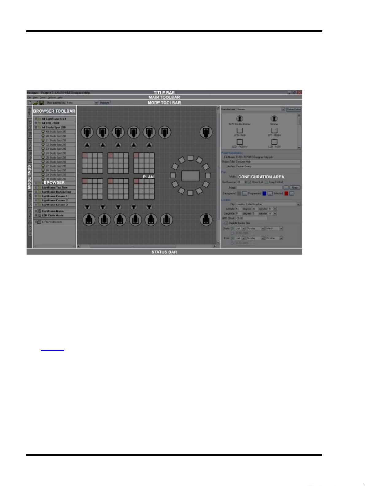
The software has been designed to present a consistent graphical user interface and so it is worth familiarising
yourself with the layout of a typical window before proceeding further:
Main toolbar
The main toolbar contains the File menu to create New projects as well as Open and Save existing projects. The
View menu accesses various optional,typically diagnostic, windows and the Zoom menu allows you quickly to
manipulate the plan or timeline scale and position. The Options menu allows you to configure various applicationwide options and the Help menu gains access to this help, software build details and the means to check for any
software upgrades.
Mode tabs
The application is divided into ten modes which can be selected by clicking on the appropriate tab. See the Quick
Start overview for a brief description of each mode and then the Reference section for more details.
Mode toolbar
The left hand end of this toolbar always carries the New, Open and Save project buttons. The remainder is populated with tools as appropriate to the selected mode.
Browser
The browser is common to most modes and provides the primary interface for selecting, expanding and grouping
fixtures in the project. The rows of the browser provide the seeds for Designer's timeline programming interface.
Some modes (Simulate, Network & Reports) have no browser since fixture selection is not relevant. Scroll bars
will appear as required and the browser can be made wider by dragging the right hand border.
- 22 -
Page 23

User Interface
Browser toolbar
The Browser toolbar provides controls for expanding and collapsing groups and compound fixtures as well as for
creating groups and Pixel Matrices.
Plan
A graphical representation of the installation that provides an interface for selecting fixtures and simulating the results of your programming. This plan simulation is one of Designer's most powerful features as it allows you to program and visually test your programming when off site. Indeed, this feature can be useful in presenting your ideas
when bidding for a contract.
Configuration area
Depending on the mode and items selected, context-sensitive configuration or control pane(s) will appear here for
fast and convenient editing.
Status bar
Context-sensitive status and progress is displayed in this area.
- 23 -
Page 24

Unison Mosaic Designer User Manual
Keyboard shortcuts
For ease and speed of use various keyboard keys map to application commands, particularly with regards window navigation:
● Function keys
● Ctrl + F8 Press to open or close the Tear-off Simulator.
● Delete / Backspace
● Esc
● Cursor keys
● Shift + cursor key Use to super-nudge a fixture selection (Setup).
● Page Up / Down Use Page Up and Page Down to zoom in and out of a plan, matrix or timeline.
● Tab
● Shift + tab
Press a function key (F1 thru F10) to change the application’s mode, akin to selecting a
mode tab on the left hand side.
Press Delete or Backspace to delete the selected fixtures or groups of fixtures, a confirm dialog will appear if this will cause fixtures to be totally removed from the project
with subsequent loss of programming. Press Delete or Backspace to delete the selected presets from a timeline.
Press Esc to clear the fixture selection. Press Esc to abort a fixture move or timeline
drag operation (preset move/resize).
Use the cursor keys to nudge a fixture selection (Setup) or scroll a matrix or timeline
(Media, Program).
Use to select the next fixture (with a single fixture selected in Setup, DALI & Mover) or
next editable cell (on a properties tab for example).
Use to select the previous fixture (with a single fixture selected in Setup, DALI &
Mover).
● Ctrl + tab Use to select the next timeline for editing (Program).
● Shift + Ctrl + tab Use to select the previous timeline for editing (Program).
● Ctrl + F Use to fit the plan or timeline to the screen.
● Ctrl + T Use to display the plan at actual size (1:1 pixel mapping).
● Ctrl + click
● Shift + click Hold Shift while clicking to select ranges of fixtures (Setup, DALI & Mover).
● Ctrl + drag
● Shift + drag
● Ctrl + A Select all fixtures (Setup, DALI & Mover) or presets (Program).
● Ctrl + N New project.
Hold Ctrl while clicking to select multiple fixtures (Setup, DALI & Mover) or presets
(Program).
Hold Ctrl while dragging a preset on a timeline to snap to the start/end of other placed
presets (Program) or while dragging a fixture selection to copy the selection using the
same relative layout (Setup).
Hold Shift while dragging a preset on a timeline for finer resolution (Program) or while
dragging a fixture selection to invert the Snap To Grid behaviour (Setup).
- 24 -
Page 25

● Ctrl + O Open project.
● Ctrl + S Save project.
Keyboard shortcuts
● Ctrl + E
● Ctrl + U Upload to the Controller(s).
● Ctrl + shift + U Save Snapshots.
● Ctrl + Q Quit the Designer application.
● Spacebar Start or pause the simulator.
● F Drops a flag in learn timing mode
Export project (exports the project including media & plan background image for transfer or backup purposes).
Notes for Mac OS X users
Unison Mosaic Designer makes a good deal of use of the two button mouse with right-click being used to invoke
context-sensitive dialogs. As the majority of Mac users have only a single button mouse they must hold Ctrl while
clicking to get this functionality. In most cases Macs use the Apple key instead of the Ctrl key except for moving
between timelines in the Program tab where Ctrl is used due to an OS Xkeyboard shortcut change. Shift and Alt
work as described for Windows.
- 25 -
Page 26

Unison Mosaic Designer User Manual
Overview
The Designer software is the tool provided to configure and program the Unison Mosaic Controllers and Remote
Devices. The Controllers have been designed specifically for the architectural and installation markets and, as
opposed to DMX frame store solutions, offer genuine lighting, audiovisual and show control functionality.
Lighting & video is programmed on timelines, with a particular timeline having control data for one, some or all the
lighting fixtures being controlled. Multiple timelines are supported and so a single unit can control multiple distinct
zones, or more complex presentations can be programmed with external triggers coming from multiple systems.
The software offers powerful functionality with a simple and intuitive graphical user interface. Most operations
can be performed with mouse clicks (typically left-click for selection and right-click for context sensitive options
& commands) and drag-and-drop. Creating a project is broken down into ten sections, use the mode tabs down
the left hand side of the application or the function keys (in brackets) to toggle between them:
Setup (F1)
In Setup you add your fixtures to the plan, arrange them in groups or customize their behaviour. Use the Properties pane to import a bitmap for the plan, set the plan’s size and grid spacing and specify the geographic location of the installation. See Setup reference.
Patch (F2)
In Patch the fixtures are assigned to the connected Controllers (see Network) and given DMX universes and
addresses. This step can be skipped during design and only completed during installation. See Patch reference.
DALI (F3)
In DALI you patch and define DALI groups & scenes for any DALI ballasts in the project. Unlike DMX fixtures,
these definitions are stored in the DALI ballasts themselves and so the configuration must be uploaded separately from here. See DALI reference.
Mover (F4)
In Mover you program presets for any automated lights with position or beam manipulation controls. These presets can then be placed onto timelines along with other programming. See Mover reference.
Media (F5)
Media allows you to create virtual video screens and map fixtures to pixels of the screen. Here you also import
and manage the media files (either static images or video) which can then be played back on these screens and
any audio visual fixtures in the project. See Media reference.
Program (F6)
Program is where you create and edit the timelines that make up your presentation. Each fixture or group of fixtures is a row of the timeline and you can drag-and-drop from an extensive range of built-in intensity and colour
effects, as well as placing mover presets and media clips. See Program reference.
Trigger (F7)
In Triggers you connect your programming with the real world. At its most basic you can define which timeline to
begin on startup but for more complex environments with external triggers you can define a detailed script, even
- 26 -
Page 27

Overview
incorporating conditions if necessary. See Trigger reference.
Simulate (F8)
Simulate allows you to view a representation of your project in plan format. You can play individual timelines to
check your programming then run the whole project including triggers. A set of buttons allow you to simulate
external triggers in order to test your programming properly. See Simulate reference.
The Simulator can also be opened in its own window so that it is permanently available, typically on a second
monitor. Tear off (click and then drag to the right) the Simulate mode tab or press Ctrl (Apple) + F8 to open this
window.
Network (F9)
This is where you manage your Unison Mosaic hardware, assigning connected Controllers to the Controllers in
your project, configuring their input/output interfaces and any attached Expansion Modules or connected Remote
Devices. See Network reference.
Report (F10)
Here you can view and organise spreadsheet-style reports listing the elements within the project for example fixture schedule, patch, triggers. This is useful in providing documentation about the installation for future reference
and to aid maintenance. Reports can be exported as *.tsv files (Tab Separated Values) for importing into an Excel
spreadsheet for formatting and printing. See Report reference.
- 27 -
Page 28

Unison Mosaic Designer User Manual
Quick Start
Creating a project
Having installed QuickTime and Designer, launch the application and select New Project from the Launch Project
dialog, choose a location for the file to be stored and give it a memorable name. A blank project will then be created and the application will enter the Setup window ready for you to configure your plan, place your fixtures and
start programming.
To create a simple Unison Mosaic Designer project we will consider these four stages:
1. Setting up your plan, fixtures and patch
2. Creating Media and Mover presets ready to use when programming
3. Programming your timelines
4. Creating the triggers that will operate your show
Getting started: Adding Conventionals, LEDs and Moving Lights to the
plan and patching them
1. From the Fixture Library pane, select Conventional from the Generic manufacturer and drag to the plan.
2. Right click (Ctrl Click for Mac users) on the inserted fixture, click on Duplicate Fixture, edit Width to 6 and
click Ok.
3. Return to the Generic Library, select LED-RGB and drag to the plan. Duplicate an 8x8 array.
4. From the library, use the drop down menu to select Robe, ColorSpot 1200, drag to plan and duplicate fixture again, this time 6 in a circle.
5. Notice the fixture browser on the left has populated each fixture in groups based on fixture type. The
middle three tree buttons above the browser allow you to expand and collapse the items. Collapse all for
now.
6. Next we will generate Pixel Matrices for applying 2-dimensional colour effects and media presets.
7. Drag a box around the LED array to select all fixtures. Click on the New Pixel Matrix button above the
browser to create a new matrix. Rename it "LED Matrix".
8. Repeat with the moving lights to create another matrix and name it all "ML Matrix".
9. Click on the Patch tab on the far left hand side of the screen to change to the Patch window.
10. Drag each group on to the blank universe to patch all fixtures. (This step is not essential to program and
simulate).
Creating Media & Mover presets
1. Click on the Mover tab at the left to change to the Mover view.
2. In the Mover Preset window click on Create New, and select the moving lights by dragging a box around
them on the plan, or click on their group in the browser.
3. In the parameter window click on the Position, Colour and Beam tabs and choose values for these attributes.
4. To create a further presets, simply leave your current programming and click Create New.
5. Click on the Media tab at the left to change to the Media view.
6. Select your LED matrix. You can move the pixels in relation to each other and resize the array window if
desired.
7. To import media click on Create New in the Media Preset window. The Designer installer provides sample
media which is located in the Designer installation directory: \resources\media_samples.
- 28 -
Page 29

Quick Start
Programming Timelines
1. Click on the Program tab at the left to change to the Program view.
2. Note the fixture browser now has timeline rows associated with each fixture, group, or matrix, and two
Mover rows have been created. Note also the preset directories on the lower right-hand side of the window: the Group directory includes built-in presets that can be applied to Group and Fixture rows, the Matrix
directory includes built-in presets that can be applied to Pixel Matrices, the Media directory has been populated with any media you imported, and the Mover directory has been populated with the Mover presets
you created.
3. Click on the Group directory tab. Select and drag the Fixed Colour preset to your All LED group, and drop
at the start of the row. You can adjust the position and length of the effect on the row by dragging it on the
timeline and selecting the handles at the end of the preset. The preset properties (in this case just colour)
can be edited in the Properties pane. Fade times and characteristics can be edited in the Transitions
pane.
4. Choose other presets from the Group directory, such as Rainbow and Sparkle, experiment with dropping
them on your groups, or open up the group and apply to individual fixtures and edit parameters.
5. To view your timeline, drag the Simulate tab at the left onto the Program view to open the Simulate window
on top of the Program window. Click on the play button to run the timeline.
6. Click on the Matrix directory. Drag these presets onto your LED Matrix row. Experiment with parameters
and simulation.
7. Click on the Media directory. Drag your media clip onto your one of your Matrix rows. Experiment with
parameters and simulation. (To experiment with the matrix size, e.g. to modify the resolution or the viewable area of the media, return to the Media window and adjust the dimensions of the matrix, the position of
the pixels, etc.).
8. Click on the Mover directory. Drag your Mover presets to one of the Mover rows. Click on the Group directory and drag intensity to the fixture / group row to apply intensity. For CMY fixtures, apply colour
effects.
9. Use the intensity preset to program the Conventional fixtures.
10. Create additional timelines by clicking on New Timeline. Name as appropriate and program.
Creating Triggers
1. Click on the Trigger tab at the left to change to the Trigger view.
2. Note that Trigger, Condition and Action directories are to the left of the worksheet area, to the right are
properties panes for editing parameters, selecting components, etc.
3. To create a Startup trigger, click Start up in the Trigger directory and drag into the main worksheet area.
Give it a descriptive comment. Drag Start Timeline from the Actions directory to the new Startup trigger
row on the worksheet, and under Action Data in the Actions pane select a timeline from the dropdown
menu.
4. Repeat, experimenting with different Triggers and different Actions. Note Change button for Real Time
parameters, and Edit for the MIDI message builder. Question marks (???) on the worksheet will indicate
where parameters or values need to be set
5. To create a conditional trigger, create a Digital Input trigger. Set it to input 1, drag a Start Timeline Action
and select a timeline to play. Copy and paste the trigger (right click / Mac Ctrl+click). On the earlier trigger
drag an Astronomical condition which will default to After Sunset. Set Action to play a different timeline.
This achieves a condition option and a catch-all option if the condition does not apply.
6. Return to Simulate. Select Project above the control area. All the triggers you have created appear below.
Clicking Play will activate the Startup trigger. Run your project, utilizing the triggers to mimic contact closures, real time triggers, serial messages, etc.
- 29 -
Page 30
Unison Mosaic Designer User Manual
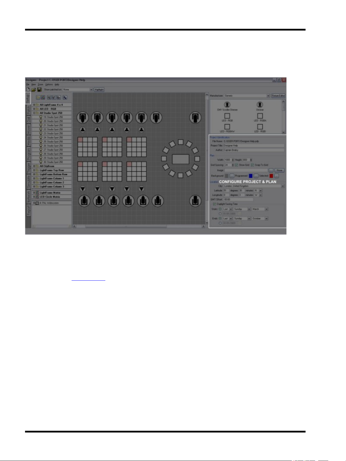
Setup - Project properties
With no fixtures selected, the Project Properties pane is displayed:
Project Identification
The project filename (*.mdp) and path is displayed for reference.
Underneath are two fields for optionally entering a project title and the project's author, these fields are displayed
on the Controller's web interface home page and are useful for reference once the installation completed.
If the title field is left blank the web interface will instead display the project's filename which may be useful for
tracking iterative versions.
Plan
Size
The plan size can be set via the Width and Height fields (in pixels) and a solid background colour selected by
clicking the Background browse button. The maximum plan size is 8192x8192 pixels.
Grid
The spacing of the working grid can be specified (again in pixels) and there are options to show this grid and
whether fixtures should snap to it. This grid is useful in accurately and easily placing fixtures.
- 30 -
Page 31

Setup - Project properties
Background image
To use a background image click on the button next to the Image entry to browse for an image, either a Windows
(*.bmp), Portable Network Graphics (*.png) or JPEG (*.jpg) image can be imported. It is envisaged that this image
be a graphical representation of the installation, perhaps derived from architectural CAD drawings.
Use the Windows Alt + Print Screen command to take a screen shot of your CAD application and then use a bitmap editor to crop and resize the image to suit (see scale). Again, the maximum plan size is 8192x8192 pixels so
make sure the bitmap is smaller or equal to these values. The plan size will automatically adjust to be that of this
image.
When planning a fixture layout, give consideration to fixture selection and visualization. Particularly with large layouts, an abstracted arrangement of fixtures may be easier to view and work with than a pixel perfect, scale accurate representation.
Scale
The Unison Mosaic Designer fixture library uses a scale of 1cm:1pixel (0.394":1pixel) for the fixture icons so, for
best results, the plan bitmap should be sized to this scale. If your installation is too large to be accommodated at
this scale (i.e. bigger than 81.92m in either axis) then change the scale and use the Fixture Position settings to
adjust the scale of your fixture icons accordingly.
Colour scheme
It may be desirable to change the colour of programmed and selected fixtures to aid clarity depending on the plan
background colour or image, use the browse buttons to select appropriate colours. A darker background makes
visualization clearer.
Location
City or Latitude/Longitude
At the bottom are the fields to set the location of the installation to ensure correct operation of the Controller's
internal astronomical clocks. A city picker is provided to facilitate the coordinate entry but values can be entered
directly into the Latitude and Longitude boxes - a web map service such as www.multimap.com is a useful
resource for collecting this information.
Time zone
The local time zone can be entered as an offset to GMT, for example New York would be -05:00 being 5 hours
behind GMT. If the city picker is used to select the location then the time zone will automatically be set.
NOTE: If such an offset is set then the Controller's date and time must be set to GMT not local time or this offset
will be doubled.
Daylight Saving Time
Check the Daylight Saving Time box to enable automatic DST adjustment. The rules for Daylight Saving differ by
region but, if the city picker is used to select the location, the correct settings for that region should appear in the
- 31 -
Page 32

Unison Mosaic Designer User Manual
Starts and Ends fields although it is recommended that you check that they are indeed valid. Alternatively, specific dates can be entered (the year is ignored).
Setup - Adding & organising fixtures
Once you have the plan setup as desired you can start populating it with the fixtures as required for the installation:
Fixture Library
Unison Mosaic Designer incorporates a comprehensive fixture library grouped by manufacturer. A generic manufacturer is provided for standard fixtures such as dimmers, basic RGB LEDs and non-dim items that need to be
switched such as fans or smoke machines.
A custom manufacturer is created when you make your own fixtures, either by right-clicking on a fixture within the
library picker (not once placed on the plan) and selecting Customise Fixture to use this fixture as a starting point,
or by pressing the Fixture Editor button at the top to create a fixture from scratch. Both operations will open the
Fixture Editor.
Note however that common settings such as colour & gobo slots, size, shape and dimmer curve etc. can all be
set on an individual fixture basis using the Fixture Configuration pane once the fixture has been deployed and
selected, so creating a custom fixture library entry,a relatively complex process, may not be necessary.
Fixture icons & scale
The following icons are used to differentiate between fixture classes:
- 32 -
Page 33

Setup - Project properties
Moving light - wash DALI ballast (see DALI)
Moving light - spot Conventional fixture
Moving light - mirror
Accessory (eg. scroller) Media server
Discrete LED fixture (to scale) Compound LED fixture (to scale)
Fountain jet fixture
4:3 PAL/NTSC AV device 16:9 PAL/NTSC AV device
The LED and compound LED fixture icons are drawn to scale (1cm:1pixel) so that, coupled with a correctly
scaled background image, the resulting plan and simulation is as realistic as possible. The other icons are drawn
to a standard size that, in most cases, will produce a realistic result. All placed fixture icons can however have
their size (scale) and even shape modified using the Fixture Configuration pane.
When using the Simulator these icons instead render the fixture's output, even displaying the selected gobo and
iris settings for moving lights. Fountain jets simulate differently however, extending in length to mimic the jet of
water.
Non-dim (switched control channel) or controller
Populating the plan
Simply chose a manufacturer, select the required fixture by clicking on it and then drag it onto its position on the
plan, it will automatically be added to the Browser and grouped with all other fixtures of that type. Once placed,
left click to select it, a red highlight will indicate the current selection, see selecting fixtures. Right click to delete,
group or duplicate fixtures.
To add a fixture:
1. Use the drop down menu at the top of the library browser to select the manufacturer
2. Locate the required fixture
3. Click and drag the fixture onto the plan and release the mouse button to drop it (it will automatically be
added to the Browser)
To duplicate a fixture (create an array):
1. Right-click on the fixture (on the plan not the Browser) to be duplicated
2. Select "Duplicate"
3. Select either "Rectangle" or "Circle"
- 33 -
Page 34

Unison Mosaic Designer User Manual
4. Set the duplication parameters, see below
5. Press Ok
For rectangular arrays, positive width and height values will place the copies to the right and below respectively,
negative to the left and above. Select either Rows or Columns to set the direction of the fixture numbering.
For circular arrays, select the radius, direction and count (number of fixtures) - complete circles are created in this
way so, if arcs required, just delete those fixtures that are unwanted.
To copy a fixture or fixture selection:
1. Select the fixture(s)
2. Press and hold Ctrl (Apple)
3. Drag the copy to a new location on the plan and release the mouse button to drop (with multiple fixtures,
their relative layout is preserved)
Note that pressing Ctrl after starting to drag will cause the selection to jump back to its original position and create a copy of the selection under the pointer.
To delete a fixture or fixture selection:
1. Select the fixture(s)
2. Press Delete or right-click > Delete
3. Press Delete to confirm (or Cancel to abort)
Note that the fixture(s) will be completely removed from the project and all programming discarded.
To see where a fixture is patched:
1. Check 'Show patched on' on the toolbar.
2. Move the cursor over a fixture - the fixture's patch will be shown next to the cursor.
3. Pick a Controller from the drop down list on the toolbar to see all fixtures patched to it - fixtures patched to
the Controller will be shown in blue.
To highlight a fixture:
1. Select one or more fixtures using the Browser or the plan
2. Press the Highlight button, the fixture(s) will come on to their highlight defaults (typically open white)
3. Press Highlight again to turn off or select other fixtures to highlight
NOTE: The appropriate Controller must be on the network and correctly associated to highlight fixtures. Fixtures
can also be highlighted from the universe tab in Patch.
DALI fixtures
DALI fixtures/ballasts are dragged onto the plan in the same way as all other fixtures but they do not populate the
Browser and no groups are automatically made since DALI fixtures are programmed and controlled via dedicated
DALI Interfaces, see DALI.
- 34 -
Page 35

Setup - Project properties
Audio visual (AV) fixtures
Select "Generic Video" from the drop down of manufacturers. Choose the appropriate type of device (PAL or
NTSC,16:9 or 4:3) and drag it onto the plan, just as you would for a lighting fixture.
However, unlike other fixtures, this will automatically add a project AVC to control that device, see Controller
Association. Similarly duplicating or deleting these AV fixtures will automatically add or delete AVCs as required.
It is important to appreciate that AV fixtures are treated differently to lighting fixtures in that they are directly
coupled to an AVC (which takes the same name) and thus require no patching. The AV fixture and its AVC should
be thought of as a single, integrated entity. See Working with the Audio Visual Controller for information about pro-
gramming AV fixtures and AVC playback.
Import fixture plan
You can use File > Import Fixture Plan to import a fixture layout from a CAD application via a CSV file, see fixture
plan file format.
Export fixture plan
You can use File > Export Fixture Plan to export a fixture layout to a CAD application via a CSV file, see fixture
plan file format. If you have any fixtures selected you will be prompted to export all or only those selected.
Fixture Identification
With a fixture selected the top two fields detail the fixture's manufacturer (manufacturer id) and model (model id),
they are for reference only and can not be edited.
Name & number
Here you can enter a new name for the fixture, useful to help make the browser easier to navigate, and the means
to change the fixture's unique user number.
Every fixture added to the project is assigned a user number which is used as a shorthand method of selecting it,
using the web interface's command line for example. Use the up and down arrows to change the number but note
that only available numbers are shown so you may need to change the number of another fixture first to make that
number available. Note that the user number does not affect the order of the fixtures in the Browser and thus the
order used for transitions.
Locked
Select "Yes" to prevent the fixture(s) from being moved or included in drag selections. Evidently, once locked,
drag selection is prohibited to select multiple fixtures to unlock so you must use the Browser instead.
Comments
Below this are two fields for entering any comments about the fixture, useful for annotating the project's documentation. These comments will appear in the fixture report and in exported CSV fixture plans.
- 35 -
Page 36

Unison Mosaic Designer User Manual
Fixture Position
Use these fields to set numerically the fixture's position and orientation on the plan and to change the size and
shape of the fixture's icon, useful for tweaking their scale to that of the plan background if the default scale not
used (1cm:1pixel).
It is desirable to position the fixtures on the plan as accurately as possible to improve both the accuracy of the programming (in particular pixel matrices created automatically from the plan layout) and the general neatness of the
project and simulation.
Grid
Use the plan properties to set the spacing of the plan's grid, whether it is displayed and whether fixtures should
snap to it. Holding Shift while dragging a fixture selection will invert the snap to grid behaviour.
Nudge
Use the cursor keys to nudge a fixture selection up, down, left or right by the amount set as the grid spacing.
Alternatively, use the up and down arrows by each of the fixture's position fields. Holding Shift while using the
cursor keys performs a super-nudge of 10x the grid spacing.
Alignment
Fixtures can be aligned to one another by making the selection and entering the value to be shared into the appropriate position field.
Fixture Configuration
This pane allows you to configure the selected fixture(s):
Intensity
The fixture's dimmer curve and maximum intensity can be set, use the Dimmer Curve pull-down to determine the
type of cross fade the intensity channel will perform and set a Maximum Intensity level, useful for balancing light
output.
DALI
DALI ballasts can be configured as allowed for by the DALI standard; Min Level (0>254), Max Level (0>254),
Power On Level (1>254) and Bus Failure level (No change, 0>254). The standard specifies a level range of 0>254
with 255 being used as a special case meaning "no change", a mask if you like. Unlike DMX fixtures, these settings are stored in the ballasts themselves and so must be uploaded separately, see DALI.
Ballasts can also have their default Fade Time and Fade Rate set in the configuration pane.
Emergency DALI ballasts will also have the option to the set the Prolong time in the configuration pane. More
information about emergency ballasts can be in the DALI topic.
NOTE: The default Fade Time and Fade Rate will be overwritten when new values are sent to ballasts during playback from triggers or programming. This is due to the way DALI ballasts store this information.
- 36 -
Page 37

Setup - Project properties
Moving lights
Moving lights can be customised for the project as one would on any sophisticated moving light console. Use
Invert Pan, Invert Tilt and Swap Pan & Tilt to normalise the way they respond to the position controls.
Customise the fixture’s gobo & colour wheels by pressing the Gobos or Colours buttons to open the Configuration
dialogs. Drag from the library onto the correct slots as required, press Ok to save or Cancel to abort.
Gel colour
For those working with gelled lights it is possible to simulate the gel’s colour so that the fixtures are rendered correctly, press the Gel button and select the required colour via the colour picker.
Reset to Defaults
Use this to force the fixture to be redefined from its library definition, losing local changes and thus restoring it to
its defaults. This is useful for updating fixtures on the plan with any library definition edits, forcing a redraw. Local
changes to a fixture's geometry (shape, size) will be overwritten.
Highlight Patched Status
On the toolbar, use the Show patched on pull-down to select a Controller and then press Highlight to highlight the
fixtures that are patched to that Controller. Select None instead of a Controller to highlight unpatched fixtures.
Press Highlight again to turn it off.
- 37 -
Page 38

Unison Mosaic Designer User Manual
Selecting fixtures
There are various ways of selecting fixtures which are common to all windows so it is worth covering them now:
Browser
The Browser is the most powerful and flexible method of selecting fixtures. Click on a group heading to select all
fixtures within the group, expand a group by clicking on the plus sign and click on fixtures within to select individual fixtures and, with compound fixtures, expand them to select the individual pixels within. Fixtures and
pixels are shown in red when selected.
Hold down Shift while clicking to select all contiguous groups/fixtures/pixels between clicks and hold down Ctrl
(Apple on Mac) while clicking to select multiple non-contiguous individual groups/fixtures/pixels. Hold down Ctrl
(Apple) while clicking to deselect a selected group/fixture/pixel.
Pressing Esc or clicking “in space” (anywhere on the Browser that isn’t a fixture) clears the selection.
The Browser also provides the interface to view and change the ordering of fixtures/pixels within groups. This
order is used by the application to determine cue timing and effects skews, simply drag fixtures about within the
Browser to change this order.
Plan
Only fixtures and pixels can be selected using the plan, to select groups you must use the Browser. Fixtures and
pixels are shown in red when selected.
Shift and Ctrl (Apple) work with clicking as described above to select/deselect and you can also lasso fixtures by
clicking and dragging around them, fixtures must be wholly enclosed to be selected.
Hold down Alt to select individual pixels within compound fixtures. Hold down Alt and Ctrl (Apple) to
select/deselect multiple pixels.
Pressing Esc or clicking “in space” (anywhere on the Plan that isn’t a fixture) clears the selection.
Select next/previous fixture
With a single fixture selected, the Tab key will select the next fixture (next higher fixture number) and Shift + Tab
will select the previous fixture (next lower fixture number).
Select all fixtures
Ctrl + A will select all fixtures.
Groups
Groups are an important concept to grasp as they serve three purposes:
Firstly, as you will see later, it is the rows of the Browser that make up the rows of the Program timeline interface
thus it is convenient to gather fixtures/pixels that are to be programmed together into a group to simplify this procedure.
Secondly, as the order of fixtures/pixels within a group determines how programming and timing is rendered, it is
sometimes useful to make multiple groups of the same fixtures with different ordering.
- 38 -
Page 39

Selecting fixtures
Finally, Groups can be used to set up intensity control zones in the Triggers window.
To create a group:
1. Select the fixtures you want to group using the Browser, the Plan or both - the order you do this in determines the order within the group
2. Right-click a member and choose Create Group From Selection or press the New Group button at the top
of the Browser
3. Name the group which has been created in the Browser containing those fixtures
Alternatively:
1. Press New Group with no fixtures selected
2. Name this empty group
3. Drag fixture/pixel selections into the group from within the Browser - the order you do this in determines
the order within the group
- 39 -
Page 40

Unison Mosaic Designer User Manual
Setup - Fixture editor
While we endeavour to provide a comprehensive library of DMX compatible fixtures, a Fixture Editor is provided
either to customise existing fixtures or create new ones:
Customised or newly created fixtures will appear in the custom manufacturer folder. However, while we build up
our database of fixture data we would actually prefer you to contact us to have your fixture added to the standard,
distributed library. Please email your fixture request(s) to support.
IMPORTANT: When edits are made to the library definition of a fixture already in the project, the plan will not
update until the fixture has been explicitly reset to its library defaults, see fixture configuration.
Electronic Theatre Controls, Inc. subscribes to the Carallon Automated Lighting Data Service.
- 40 -
Page 41

Preferences
Select Options > Preferences on the main toolbar to open the Preferences dialog:
General
Select the General tab to change the default behaviour of Designer:
Preferences
Intensity model
Choose whether intensity and DALI presets are programmed using Percent (0>100%) or 8-bit (0>255) values.
Colour model
Choose whether colours are specified using RGB (additive) or CMY (subtractive) values, the latter might feel
more natural for moving light console users.
Number of backups
Designer can keep a number old versions of the project file when you save and it is here that you set the number
of old files to keep. Before saving your project (File > Save or Ctrl+S), Designer will rename the project file on
- 41 -
Page 42

Unison Mosaic Designer User Manual
disk by adding the current time and date to the file name, such as "my_project_bak_2007-04-18_15-58-09.mdp".
If you already have the specified number of backups, the oldest backup will be removed from the disk.
Use File > Save As to produce manual backups of the project at each important programming milestone.
Autosave interval
Designer can periodically create an automatic backup of your programming and it is here that you turn this feature
on and set the backup interval in minutes. Designer will maintain a backup file named "my_project_auto.mdp"
which can be opened to retrieve recent programming in the event of a software crash. This file will be deleted if
the Designer project is closed normally.
Show Launch dialog
Choose whether the Launch dialog is automatically opened at startup (default), uncheck this box to suppress this
dialog.
Close Upload Dialog after successful Upload All
Check this to have the Upload Dialog close automatically after a successful Upload All.
Saving Projects from Old Version
Choose what Designer should do when saving projects that were last saved in an earlier version of the software.
This can be a useful prompt to keep a backup of your work.
Patch
Select the Patch tab to change the default settings for patching:
- 42 -
Page 43

Preferences
Channels per row
The Channels per row entry box lets you determine how many DMX channels per row are displayed which is useful for organising the display for complex fixtures; set this number to be a multiple of the number of channels a fixture uses to get a neater, tabulated display.
Timeline
Select the Timelines tab to change the default settings for timelines and presets:
- 43 -
Page 44

Unison Mosaic Designer User Manual
New timeline properties
Specify the default name and length for subsequently created timelines, see timeline properties.
New preset properties
Specify the default properties for subsequently added presets, see preset types and properties.
Background Colour
The background colour of the timeline area of the Program window can be chosen here, press the button and
select a colour. This is useful to make certain types of programming stand out better, for example a project using
mainly intensity presets may be clearer with a dark grey background.
Triggers
Select the Triggers tab to change the default settings for triggers:
- 44 -
Page 45

Preferences
Short MIDI data format
Select the default Short MIDI message data format to be either Decimal or Hexadecimal.
- 45 -
Page 46

Unison Mosaic Designer User Manual
Network
The web interface (HTTP) and file transfer (FTP) ports used when an MSC is connected via USB can be configured.
- 46 -
Page 47

Advanced
Preferences
Enable or disable using Winamp as a timecode source in Simulate. This feature is available on Windows only.
- 47 -
Page 48

Unison Mosaic Designer User Manual
Patch
Once you have created your plan and added your fixtures you need to patch them, that is to say connect them to
real fixtures via the appropriate Controller (MSC 1, 2, 4 or X), interface (port), protocol and address. Patching is
optional for programming and simulation but fixtures must be patched eventually for the MSCs to control them,
including using Output Live in the Simulator.
NOTE: The AVC does not require patching.
Before we cover patching in detail let's look at some of the terms used:
Patch terminology
Term: Description:
DMX A digital serial control protocol for entertainment lighting. Officially called
DMX512-A, it was developed by the USITT and has become the standard protocol for entertainment lighting control using the RS485 physical layer.
RDM Remote Device Management, an extension of the USITT DMX512 protocol
that supports bi-directional communication with dimmers & fixtures.
eDMX A shorthand term for DMX-over-Ethernet protocols, see KiNet, Art-Net II, Path-
port and sACN below.
KiNet A proprietary Ethernet control protocol developed by Color Kinetics (now
Philips Solid State Lighting) used to control only their Ethernet PSUs.
Art-Net II A DMX-over-Ethernet protocol developed by Artistic Licence and widely used
in the entertainment industry to distribute multiple universes of DMX data.
Pathport A DMX-over-Ethernet protocol developed by Pathway Communications and
widely used in the entertainment industry to distribute multiple universes of
DMX data.
sACN Streaming ACN (Advanced Control Network), a DMX-over-Ethernet protocol
developed by ESTA to distribute multiple universes of DMX data.
RIO The ETC Remote Input Output 80/44/08 can output up to 96 channels of DMX
per unit. See here for more information on patching to a RIO.
DVI Digital Video Interface, a standard for the delivery of digital video data to com-
puter monitors. Used by certain LED manufacturers (for example Barco and
Martin Professional) to drive their LED controller products.
DALI Digital Addressable Lighting Interface, a digital serial control protocol for archi-
tectural lighting. Developed by Philips Lighting it has become a standard: IEC
60929. DALI fixtures are not patched using this window, see DALI.
Universe A common term given to a single DMX data link or port. A DMX universe car-
ries 512 channels of control data each with 8 bit resolution. A single dimmer
will use one channel while more complex fixtures will use multiple channels as
required.
Port The KiNet equivalent to a universe.
DMX Address The term used to determine which of the 512 control channels of a DMX uni-
verse a fixture should look at to take its own control data. This "start address"
must be set on the fixture or dimmer rack itself as well as patching the control
system.
For more
information:
USITT
DMX512
RDM
ESTA
DALI
- 48 -
Page 49

Patch
Patch window
This window comprises three sections, to the left is the Browser, to the right the Protocol configuration pane, with
the rest of the window being a graphical representation of a protocol's port or universe. The number of address
columns displayed per row can be changed using Options > Preferences > Patch.
If you are using an MSC X or choosing to output eDMX from an MSC 1 or 2 then you must use the Protocols pane
to configure these protocols, see Controller Protocols.
Patch toolbar & protocol tabs
Use the Controller pull-down to select the Controller for patching. Use the Hide Unused Universe button to suppress unpatched universes and the Highlight button to bring the selected fixture(s) to its highlight values, typically
100% intensity in open white for easy identification.
Use the tabs across the top of the graphical area to select the required protocol and then the universe or power
supply & port pull-downs to select the target for patching which will be graphically displayed.
Patching DMX & eDMX fixtures
Simply select one or more fixtures in the Browser and drag them onto the required start address of the graphical
representation. Right click on a patched fixture to unpatch it or clear the entire universe/port, drag it to move it
(change its address). Fixtures may be patched to multiple addresses and universes/ports. Patched fixtures are
shown in blue in the Browser, unpatched black.
To patch a fixture:
1. Use Controller and Universe to select the desired Controller and universe of this Controller (if the Controller has multiple universes)
- 49 -
Page 50

Unison Mosaic Designer User Manual
2. Select the fixture in the Browser
3. Drag and drop the fixture onto the desired start address
To patch multiple fixtures:
1. Use Controller and Universe to select the desired universe
2. Select a group of fixtures in the Browser (see selecting fixtures)
3. Drag and drop the group of fixtures onto the desired start address of the first fixture in the selection
To change a fixture's address:
1. Use Controller and Universe to select the universe on which the fixture is patched
2. Select the fixture(s) on the universe layout and simply drag them to a new address - to move them to
another universe you must unpatch (see below) then repatch
Fixtures may be patched to as many locations and universes as is required although typically a fixture will only be
patched to one unique address. The Designer software will prompt you with a warning dialogue should you
attempt to patch a fixture that is already patched, select Continue or Unpatch Existing as required. This prompt
can be turned off if it proves aggravating.
However, you can not patch more than one fixture to the same address; a DMX channel can only be controlled by
one parameter so fixtures can't overlap at all. If you drag one fixture onto another the incoming fixture will highlight
in red to alert you that this address is already occupied. If you go ahead and drop it there anyway the software will
prompt you whether to continue and unpatch the existing fixture(s) for you,select Ok to proceed or Cancel to
abort. Again, this prompt can be turned off.
Some fixtures, for example the Vari*lite VL5, need to be patched twice since they have two distinct patch points,
one for the intensity control (patched to the dimmer rack) and another for the fixture's automation controls.
To patch a multiple patch point fixture:
1. Locate the fixture in the Browser and expand it by pressing the plus sign to reveal its patch points
2. Use Controller and Universe to select the desired universe for the first patch point
3. Drag and drop the first patch point onto the desired start address
4. Repeat for the other patch point(s)
or
1. Patch the entire fixture as one
2. Drag the patch points apart to their desired addresses
To unpatch a fixture or multiple fixtures:
1. Select one or more fixtures using the Browser or the universe layout
2. Right-click and select Unpatch
To clear all patching from a universe:
1. Use Controller and Universe to select the universe to be cleared
2. Right-click anywhere on the universe layout and select Clear Universe
- 50 -
Page 51

To clone a universe (copy the patch):
1. Use Controller and Universe to select the universe to be cloned
2. Press the Clone Universe button to open the Clone Patch dialog:
3. Select the target Controller, Protocol and Universe using the pull-down
4. Press Ok to clone the patch to this universe or Cancel to abort
To highlight a fixture:
1. Select one or more fixtures using the Browser or the universe layout
2. Press the Highlight button, the fixture(s) will come on to their highlight defaults (typically open white)
3. Press Highlight again to turn off or select other fixtures to highlight
Patch
NOTE: The appropriate Controller must be on the network and correctly associated to highlight fixtures. Fixtures
can also be highlighted from the plan in Setup.
To hide unused universes:
1. Select the Controller
2. Press the Hide Unused Universes button, only universes with patched fixtures will be displayed
3. Press Hide Unused Universes again to display all or select another Controller
RDMdevice discovery
- 51 -
Page 52

Unison Mosaic Designer User Manual
In the DMX patch tab, press 'Discover' to find RDM-capable devices attached to the current Controller. The Discover button is only enabled if the current Controller is associated with a physical Controller and that Controller
has been found on the network.
Toggle 'Show Discovered' to show and hide the discovered RDM devices.
To identify a device, toggle the button in the Identify column of the table. To readdress a device, enter a new
value in the Start Address column.
KiNet device discovery
In the KiNet patch tab, press 'Discover' to find KiNet power supplies.
NOTE: KiNet discovery is performed via the network interface of the computer running Designer, not via the Con-
trollers. If the computer has more than one network interface then you will be prompted to select which network
interface to use for KiNet discovery. The network interface must have an IP address in the 10.x.x.x range for discovery to be completely successful.
Toggle 'Show Discovered' to show and hide the discovered power supplies.
Power supplies that have an IP address that is already used by the current Controller will appear in grey.
To add a power supply to the current Controller, press the button in the 'Select' column and press 'Add To Project'. A new power supply will be added to the current Controller and that power supply will be automatically selected. If Designer doesn't recognise the type of the power supply, you will be prompted to select it from a list.
To add all the discovered power supplies to the current Controller, press 'Add All To Project'.
Patching fixtures to a RIO
- 52 -
Page 53

Patch
In the RIO section of the patch tab you'll need to add a universe that will joined to a RIO before you can patch fixtures. Click 'Add Universe' and choose the RIO to which you want to output that universe of DMX.
The RIO is capable of outputting 96 channels of DMX. Any channels patched to a RIO will subtract from the maximum channel output capacity of the Controller. The RIO and Controller must be on the same network.
Patching DVI fixtures (MSC X)
To output data using the DVI port you must first create a pixel matrix that matches the LED controller's pixel map.
Once this has been done, use the Pixel Matrix pull-down on the protocol tab to select which matrix will be output
via the DVI port and select an X & Y offset as required. Any programming for the fixtures in the pixel matrix will
now output on the DVI port, not just programming applied directly to the pixel matrix.
The MSC X's DVI port is set to a fixed 1024x768 @ 60Hz resolution which is compatible with most LED controllers. The LED controller (or monitor) MUST be connected when the MSC X boots or resets for the port to
become active.
Used channels
At the top of the Protocols pane is an indicator of the number of used and available channels for the selected Controller.
When the Controller is an MSC X, and if you have not associated the controller with a physical device, then you
are allowed to patch fixtures up to the capacity you have chosen (see Controller Association).
However, when you associate an MSC X with a physical device, you will only be able to associate to devices
which have a capacity equal or greater than the patched fixtures. After associating with a device, you will be
unable to exceed the capacity of that device.
eDMX Pass-Thru
When using an MSC in a project it is possible to allow eDMX from another eDMX source to be passed through to
the controller’s DMX ports. With an MSC selected, the bottom of the protocols pane will show the eDMX PassThru settings. Select which universe the DMX port will be transmitting. Note that with an MSC 2 you'll be able to
choose a different universe for each DMX port on the controller. There is also the option to auto-revert to the project’s output if eDMX isn't received for a specified amount of time.
Note that only Art-Net and sACN are currently supported for eDMX pass-thru.
Art-Net output customisation
By default, a controller with less than 30 universes of Art-Net patched will broadcast all data until a device
requests unicast for a specific universe. Controllers with more than 30 Art-Net universes patched will only unicast data to devices requesting universe data and will not automatically broadcast.
There is the option to 'Disable Broadcast' for a controller. The controller will still unicast data to devices that
request it. There is also the option to 'Always Broadcast' on a per universe basis. This will force the controller to
always broadcast that universe's data. 'Always Broadcast' will override the 'Disable Broadcast' option.
- 53 -
Page 54

Unison Mosaic Designer User Manual
DALI
This window need only be used if there are DALI ballasts in the project and one or more RIO Ds or DALI-M Expansion Modules are being used.
Overview
The Digital Addressable Lighting Interface (DALI) is a digital serial control protocol for architectural lighting.
Developed by Philips Lighting it has become a standard: IEC 60929. DALI differs from DMX in a number of important ways:
l Only 64 ballasts per DALI bus (interface)
l Only 16 groups per interface
l Only 16 scenes per interface
l Ballast configuration (including address), groups and scenes is uploaded to and stored in the ballasts them-
selves
l Topology-free DALI bus operates at very low data rates
l Command-based protocol, ballasts perform fades and maintain levels
l Only certain discrete fade values are permitted
As a result the DALI protocol is not suitable for rendering effects and media, programming is restricted purely to
recalling lighting levels via the Set Level and DALI Scene presets, see DALI presets.
DALI interfaces
Each RIO D, TPC with TPC-RIO or DALI-M Expansion Module added to the system supports one DALI bus (up
to 64 ballasts) and is assigned to a DALI interface within Designer. Due to the nature of the DALI protocol, these
DALI interfaces are insular affairs with each having its own unique set of ballasts and groups. Each interface
must be configured and uploaded to individually.
When you add a RIO D, TPC with TPC-RIO or DALI-M Expansion Module you select which DALI interface it
should be assigned to. Only one device can be assigned to each interface. Use the Add Interface button on the
DALI toolbar to add another. Use Remove Interface to remove an unwanted one.
Up to 100 DALI interfaces can be added to a project, but the following restrictions apply:
l A TPC or an MSC 1 can support up to 16 RIO Ds.
l An MSC 2 can support up to 32 RIO Ds.
l An MSC 4 can support up to 64 RIO Ds.
l An MSC X can support up to 100 RIO Ds.
l An AVC cannot support any RIO Ds.
l The original MSC 1/2 hardware each support up to two DALI-M Expansion Modules.
DALI addressing & grouping
Each DALI interface is configured separately, use the pull-down on the DALI toolbar to select an interface for configuration:
- 54 -
Page 55

DALI
The top pane of the DALI interface window displays the 64 real ballast address cells, the bottom pane the group
membership matrix. The device commands are available to manage the ballasts on each DALI interface.
Device commands
IMPORTANT: Designer must be connected to the Controllers with RIO Ds or DALI-M Expansion Modules and
the DALI ballasts must be active to perform these operations.
A DALI ballast internally stores its address, this is a number between 1 and 64. It is also possible that the ballast
has never been addressed so it does not have an address. These commands are used to discover and address
DALI ballasts:
Find addressed ballasts
This queries the ballasts attached to the device and reports all addressed ballasts found, an icon is added to each
address cell when the corresponding ballast has been found.
Address ballasts
This finds all ballasts without an address and randomly assigns them a free address. It will not change the
address of any already addressed ballasts.
Readdress all ballasts
This will clear the addresses of all ballasts and then assign every ballast a random address.
- 55 -
Page 56

Unison Mosaic Designer User Manual
Resolve clash
It is possible that two ballasts can have the same short address. If that happens the ballasts clashing are shown
with a red icon. The resolve clash button will move the clashing ballasts to a random address that is unused by
any other ballast.
Identify emergency ballasts
Send all emergency ballasts a command to indicate their address on the multicoloured LEDs on the fixture.
Whilst this is enabled the command will be sent every 10 seconds.
To manually readdress a DALI ballast:
1. Select the ballast icon in the current address cell
2. Drag it to the target (preferably empty) address cell
The ballast is readdressed to the target cell. If the target cell was occupied then the ballasts should swap
addresses although this has not been found to be terribly reliable.
To highlight a ballast
Select an address cell (containing a ballast icon) and press Highlight to bring this ballast to full level, select
another cell to highlight instead or press Highlight again to turn off.
Patching DALI fixtures
When you add DALI fixtures to your project plan in setup these "abstract" ballasts are assigned to the Unpatched
DALI group in the Browser and must be mapped to real DALI interfaces and ballasts using this window.
Once you have discovered and addressed all the real DALI ballasts for each interface (if more than one) you can
then patch your DALI fixtures to them simply by dragging them from the Unpatched DALI group onto the required
interface and address cell. As each DALI interface is assigned DALI fixtures, the Browser refreshes to reflect
these changes. The Unpatched DALI group will become empty once all the DALI fixtures in the project have been
patched.
It is of course possible to patch your DALI fixtures blind in advance of being connected to the real ballasts. The
patch is stored with the project data and not on the DALI ballasts.
DALI groups
Unlike other groups in Designer, DALI groups are a property of the real DALI interface not an abstract collection
of fixtures, and there can only be 16 DALI groups per interface. The matrix on the lower pane of the window
allows you to add and define groups for each interface:
To add a DALI group:
1. Press the Add button
2. Type a name by double-clicking the name cell
- 56 -
Page 57

DALI
3. Select which ballasts are to be a member by double-clicking the ballast's cell
The DALI group is added to the Browser and group configuration data ready to be uploaded into the ballasts.
To delete a DALI group:
1. Right-click on the group in the Browser
2. Select Delete
3. Press Ok to confirm
The DALI group is removed and the group configuration data updated ready to be uploaded into the ballasts.
If groups have already been programmed onto the DALI fixtures you can press the Discover Groups button to
automatically populate group information from the fixtures on the interface.
DALI scenes
In Designer's implementation, DALI scenes are common across DALI interfaces, use the pull-down on the DALI
toolbar and select Scene Setup for programming:
The Browser and project plan are displayed so that you can select the DALI fixtures and groups. On the right are
the DALI scenes folder and the Intensity controls.
There can be up to 16 DALI scenes which can contain programming for some or all of your DALI fixtures, even if
spanning different DALI interfaces. In general you should include programming for all your DALI fixtures in each
scene since you can determine when creating timelines which fixtures or groups should run the scene by dropping the DALI scene on the appropriate timeline row, the choice is yours though.
- 57 -
Page 58

Unison Mosaic Designer User Manual
To create a DALI scene:
1. Press the Create New button
2. Name the new scene
3. Select the DALI fixtures or groups
4. Set the required level (0>254), the fixtures on the plan will simulate these levels
The DALI scene is added to the folder and scene configuration data is ready to be uploaded into the ballasts.
To delete a DALI scene:
1. Select the scene in the folder
2. Press Delete
3. Press Yes to confirm
The DALI scene is removed and scene configuration data updated ready to be uploaded into the ballasts.
To edit a DALI scene:
1. Select the scene in the folder
2. Select the DALI fixtures or groups
3. Adjust the levels
The DALI scene is edited and scene configuration data updated ready to be uploaded into the ballasts.
To remove a DALI fixture from a scene:
1. Select the scene in the folder
2. Select the fixture to remove
3.
Press the Knockout button to the right of the Intensity controls
The DALI scene is edited and scene configuration data updated ready to be uploaded into the ballasts.
Emergency Ballasts
Emergency DALI ballasts are set-up in the same way as standard DALI ballasts and support Highlight and ReAddressing.
Emergency tests may be scheduled for all emergency ballasts in a project via the Emergency Ballast Tests tab
on the right of the DALI window. You can override project settings on a per interface basis by using the emergency settings in the Interface Properties tab. Function and Duration tests can be scheduled independently of
each other on a daily, weekly, monthly or yearly basis. The time of day that the tests run can also be specified.
Choosing to test alternate ballasts will test every other patched ballast - the remaining ballasts will then be tested
once the initial test is complete.
- 58 -
Page 59

DALI
Test information is stored on the memory card of the controller responsible for that interface. This information can
also be viewed via the web interface.
Specify a ballast's Prolong time in the Setup tab.
Upload configuration
Once you have configured all your DALI interfaces and programmed all your DALI scenes you must upload the
configuration to each DALI interface in turn so that this data can be stored on the DALI ballasts themselves.
Select an interface using the pull-down on the DALI toolbar and press the Upload Configuration button, a progress
bar will track this rather slow procedure.
- 59 -
Page 60

Unison Mosaic Designer User Manual
Mover
This window need only be used if there are fixtures in the project that have control parameters other than intensity
and colour mixing. Examples include most automated lights which, above and beyond position (pan & tilt), might
also include gobo and effects wheels:
The Mover window is where one sets these other parameters and it comprises four sections: On the left is the
Browser, in the middle the Plan. Top right is the directory of Mover Presets within the project and below that is the
Fixture Parameters pane and it is here that parameters other than intensity and colour mixing are set.
Parameter kinds
Parameters are grouped by kind:
Intensity Parameters excluding intensity (which is programmed directly on the timeline) such as strobe
Position Pan and tilt
Colour
Beam Image Gobo and effects wheels
Beam Shape Iris, zoom and focus etc.
Control Lamp and fixture controls such as dowse, strike, reset and macros
Setting one parameter within a kind sets or “touches” all the rest, the kind heading will turn blue and the Knockout
button will be enabled to indicate that programming for this kind is included in the preset.
To remove programming press the Knockout button to the right of the kind heading to “untouch” these para-
meters.
Parameters excluding colour mixing (which is programmed directly on the timeline) such as
fixed colour wheels and scrollers, colour correction
- 60 -
Page 61

Mover
Effects
A realtime effect can also be applied to any parameter by pressing the associated FX button which opens the
effect controls for adjustment, pressing FX again turns off that effect.
Effects work by modulating the programmed base value with a low-frequency oscillator (LFO):
l Effect - the shape of the LFO's waveform (Square, Triangle, Sawtooth, Sine or Cosine)
l Size - the amplitude of the modulation, adjust in conjunction with the base value
l Period - the number of seconds over which the waveform will repeat, the higher the period the slower the
effect
l Style - choose None (all parameters are modulated together) or Spread (the effect is spread over space as
well as time)
Position
The Position kind is a special case in that a) a graphical position picker is provided and b) the pan and tilt effects
are linked and displayed/adjusted graphically. Hold Shift while dragging for fine resolution or use the Pan and Tilt
fields provided underneath for accurate, numerical positioning. Note that you can also lock an axis by clicking on
the Pan or Tilt button which allows positioning of one axis without interfering with the other.
Creating a mover preset
Click Create New to make a new preset and type a name. Select the fixtures, which will automatically come on
to 100% so that you can see what you’re doing, set their parameters and add effects to these parameters as
required. The fixture icons on the plan will provide graphical feedback of what they’re doing. You will not be able to
select any fixtures unsuitable for making mover presets. Use the Transition section to give the preset a default
fade time and skew type, the preset is now ready for use.
Mover Presets can be created to contain programming for all kinds (complete look) or just a single kind, for
example Colour presets or Position presets, akin to palettes on a moving light console. This latter method allows
for more flexibility when programming the timelines as you can mix and match these kind presets to make complete looks on the fly. It also allows different transitions to be applied to each kind so that gobos could fly in one
after another (using a skew) while position moves more slowly and as a whole (longer fade, no skew).
Using Output Live
While the mover icons give a fair degree of feedback about your programming, by visualising colour and gobos for
example, other parameters are not visualised and so must be programmed live, press the Output Live button on
the main toolbar to do so. Output Live is not possible without patched and associated Controllers.
Note that if you wish to program or edit a preset that requires one or more other presets to be on stage, for
example rotating, zooming and focusing a gobo where the position is set by another preset, then you must also be
simulating a timeline that runs those presets.
Editing a mover preset
To edit an existing preset just click on it and select the fixtures for adjustment, note that included fixtures will be
shown with a blue halo on the plan and fixtures currently selected for edit with a red halo. Any timelines on which
the preset is deployed will automatically update to reflect the edits made.
- 61 -
Page 62

Unison Mosaic Designer User Manual
Deleting and copying a mover preset
Right click on a preset to delete or copy it, the latter function being useful in making similar presets that vary only
slightly, say just the gobo being used.
- 62 -
Page 63

Media
Media
This window serves two purposes: to edit or manually create Pixel Matrices of fixtures for use as a media playback screen, and to import Media, AVC & Custom Presets into the system:
The window comprises 3 sections: On the left is the Browser, in the middle the Pixel Matrix editing area, and on
the right are the Presets panes.
Pixel Matrices
To create Pixel Matrices automatically from the plan (recommended):
1. Go to Setup
2. Select the fixtures you want to include in the Matrix
3. Press the New Pixel Matrix button on the Browser toolbar, the software will automatically create a Matrix
with the fixtures correctly positioned and the Render Window cropped to best fit
4. Name the Pixel Matrix using either the textbox on the toolbar or right-clicking>Rename in the Browser
To create a Pixel Matrix manually:
1. Press Create New on the toolbar, a default 50x50 Render Window (the hatched area) will be created and
the Browser populated
2. Populate the Render Window by dragging on fixtures from the Browser
3. Adjust the size of the Render Window by using the Width & Height fields on the toolbar or the Crop button
(see below) to best fit
4. Name the Pixel Matrix using either the textbox on the toolbar or right-clicking > Rename in the Browser
- 63 -
Page 64

Unison Mosaic Designer User Manual
Typically you will place fixtures to mimic as closely as possible their actual deployment, the software will compensate for gaps and irregularities in a matrix so that media will be rendered correctly. Fixtures that have been
rotated on the Plan during Setup will be placed on the Matrix using this rotation although this is only relevant to
compound fixtures. Such fixtures can be rotated separately for each Matrix by dragging them around when the
cursor indicates rotate mode, note that the first element of a compound fixture is displayed a darker pink for easy
orientation.
To remove a fixture from a Matrix right-click on the fixture on the plan and select Remove Fixture.
To break a composite fixture apart into individual pixels right-click on the fixture on the plan and select Break Fixture.
You may create as many Matrices as you like and any fixture can be used as a “pixel” in any Matrix but clearly
those that can colour mix are the sensible choice, RGB LEDs being by far the best due to their large colour gamut
and fast response. That being said, the software will render coloured media as grey scale on intensity only fixtures.
Crop render window
Use the Crop Render Window button to trim the Render Window to fit the extents of the fixture array.
Manual sizing of the Render Window is provided by typing in appropriate Width and Height size values and it is
perfectly allowable to undersize the Render Window to achieve effects such as picture-in-picture or oversize it to
concentrate on a particular area of the imported media.
Import pixel matrix
You can use the Import button to import pixel layout from a CAD application via a CSV file, see pixel matrix file
format.
Media Presets
Select the Media tab. Media presets can only be played on MSC Pixel Matrices.
Media is imported by clicking Create New in the Media Presets pane. A dialog will open as shown above for you
to browse to wherever your media files are located, enable Thumbnails view to preview them. Designer supports
most common media files, indeed anything that QuickTime supports, and it matters not at all the resolution of the
media clips as the software will up/down-scale as required when the Media Preset is placed on a Matrix during
programming. In short, no media preparation should be required. The first frame is used as their thumbnail in the
directory, they can be named using the name textbox at the bottom of the directory pane and they can also be
deleted.
Imported Media is automatically resized to fit a Pixel Matrices’ Render Window, the hatched area of the Matrix.
Only fixtures/pixels within this Render Window will receive the media which is why Render Windows should typically be cropped (see above) to force the media to fit onto just the fixtures.
Designer ships with sample media clips kindly provided by Projected Image Digital, Mode Studios and
Digigobos. Four samples are installed with the application, the others reside in the Sample Media folder on the
CD. Links are provided from the Media window to peruse these vendors’ websites to obtain additional media for
your project.
- 64 -
Page 65

Media
Media Slots
Select the Media Slots tab. Media slots are placeholders for Media Presets and can only be played on MSC Pixel
Matrices.
Create a Media Slot by clicking Create New in the Media Slots pane. A Media Slot can be renamed using the
name text box underneath the Media Slots directory. The selected Media Slot can be deleted by clicking the
Delete button.
The content for Media Slots is created using a separate utility application: Unison Mosaic MediaManager. When
you have finished creating your Designer project, go to File > Export for Media Manager to save details about your
Media Slots to a .mdx file. Create a new project in MediaManager and import the .mdx file. You can now program
content onto each media slot. It is possible to import .mdx files from multiple Designer projects into a single MediaManager project in order to aid media management for large installations. Please refer to the MediaManager help
for further details.
Whenever you make a change to the fixtures, patch or programming in your Designer project you must go to File
> Export for Media Manager and then import the generated file into your existing MediaManager project.
When you've exported your media from MediaManager you can upload it to your controllers using Unison Mosaic
RemoteManager. Please refer to the RemoteManager help for further details.
AVC Presets
Select the AVC tab. AVC presets can only be played on AVCs, see Working with the Audio Visual Controller.
You must prepare the video and audio clips you want to use on the AVC in this pane. To add a new clip click
Create New and browse to a suitable media file containing video, audio or both.
Should the media file(s) subsequently be moved, renamed or deleted such that the preset path(s) no longer valid
then a warning icon will be displayed over the thumbnail.
Designer can import a wide variety of video formats and convert them into the video format used on the AVC.
However, the AVC format is based on MPEG2 and for best quality results - and fastest conversion - we recommend preparing content as standard definition MPEG2. All video content must have either PAL (25fps) or NTSC
(29.97fps) frame rates - Designer will not accept content with other frame rates, but it will scale video prepared for
different resolutions.
Designer can also import a wide range of audio formats including AC3 (used on DVDs), WAV, and MP3. To add
audio to an existing clip, make sure the clip is selected and click on the button next to the "Audio Path" box. You
can then browse to the audio file and select it.
If the video and audio need to be synchronised (i.e. audio is a soundtrack for the video) then you should select
"Audio synced" to ensure they are always locked together. You can specify an audio offset to correct for any time
delay between video and audio. If the audio and video can run independently (e.g. audio is a music track of a different length to the video) then make sure "audio synced" is not selected and they will loop independently.
Custom Presets
Select the Custom tab. Custom presets can only be played on MSC Pixel Matrices.
Custom Presets use a Lua script to define an effect that can be played back on a Matrix. You can use this to cre-
ate effects that are not available as standard in Designer.
- 65 -
Page 66

Unison Mosaic Designer User Manual
To create a new Custom Preset, press Create New in the Custom tab on the right. This will open a script editor
dialog:
The source editor initially shows the framework of a custom preset. You can either enter the source yourself, or
you can load the source from a file using File > Import. Designer provides sample scripts which are located in Program Files at \ETC\Mosaic\Designer\resources\scripts\custom_presets.
After editing or importing a script, you compile it by pressing F7. If there are any errors in the script, they will be
reported in the Output tab. If there are no errors reported, it is advisable to run the script to preview the preset. To
run the script, use Debug > Run (F5). If the script takes a long time to run, or appears to have got stuck in a loop,
use Debug > Stop (Ctrl+F5) to stop execution.
IMPORTANT: When working in the script editor, if your script does have an infinite loop, you are able to stop it
executing by pressing Debug > Stop (Ctrl+F5). However, outside of the debugger, there is no such way to stop
the execution of a badly-behaved script. This will result in Designer locking up and will have to be shut down
manually. You must ensure that your scripts do not have such errors in them.
A preview of the preset will be generated and shown on the right of the script editor. You can start and stop the preview and step forwards and backwards with transport controls below the preview. Altering the period below the
preview and pressing Debug > Run (F5) again will generate the preview again with the specified period.
If the preset defines any properties, after the script is successfully compiled, suitable editors for these properties
will be displayed below the preview. You can change the values of these properties and rerun the script using
Debug > Run (F5) to observe the effect of those properties in the preview.
Once you are happy with the preview, close the script editor. The preset can now be placed on Matrices on a
timeline.
You can edit the source of the custom preset script again by selecting it in the Custom tab on the Media pane and
pressing Edit. If you edit a preset that is already used on a timeline, any changes you make will be applied to
everywhere where the preset is used.
Refer to the script editor documentation for more information on editing scripts, and the custom presets pro-
grammers guide for help on creating a custom preset from scratch.
- 66 -
Page 67

Program - Timeline Properties
With no presets selected, the Timeline Properties pane is displayed:
Program - Timeline Properties
Name
Give your timeline a name here, a descriptive name will help you identify the correct timeline when creating basic
triggers and viewing the web interface's status and control pages.
Number
Every timeline has a unique number which is primarily for reference but can be changed if necessary. The
timeline number is used to identify a timeline for creating advanced triggers, for example when using LUA scripts,
and when using the web interface's command line.
Length
The default timeline length is 05:00.00 (5 minutes) and you will need to increase this before placing or extending
presets beyond this time. The maximum timeline length is 24 hours to prevent them becoming unmanageable use triggers to stitch together multiple timelines to create longer time frames.
Priority
Use the pull-down to select a priority level for the timeline:
l High - the timeline will never be overridden
l Above normal
l Normal - the timeline behaves normally and can be overridden
l Below normal
l Low - the timeline can not override other timelines
- 67 -
Page 68

Unison Mosaic Designer User Manual
Time source
Use the pull-down to select a time source for the timeline to follow:
l Internal - the timeline will run autonomously although playback speed and position can be overridden using
triggers.
l Timecode Bus - the timeline will follow one of six Timecode Buses (see below).
l Audio Bus - the timeline will follow one of four Audio Buses (see below).
Working with timecode
By selecting one of the six Timecode Buses, the timeline's ruler will display timecode values and the properties
pane will give further options:
Time Offset
Timelines by default start at 00:00:00.00 (hours:minutes:seconds.frames) but the timecode source may not do
so, the tape may have been "striped" with an offset of an hour (01:00:00.00) for example. Enter the source's starting value in this box to synchronise.
Format
Timecode comes in four formats that depend on the source media used, select the appropriate format here
(Film24, EBU25, SMPTE30 & NTSC30) to prevent missed frames and stuttering playback.
Auto release at end
Check this box if you want the timeline to release, and hence ignore timecode, at the end (the end of the last
placed preset or flag). Typically leave it unchecked so that the timeline always follows the timecode regardless of
the timecode value which may exceed the end time.
Timecode Buses
The six Timecode Buses are internal buses to which one patches the external timecode sources available to the
system. These may be MIDI timecode (MTC) sources input via one or more MSCs' or RIO As' MIDI Inputs or linear timecode (LTC) sources input via one or more RIO As or LTC Expansion Modules. You can use the Timecode
Viewer available from the View menu to monitor each Timecode Bus:
- 68 -
Page 69

Program - Timeline Properties
Working with audio
By selecting one of the four Audio Buses, the properties pane will give further options:
Band
The Audio Expansion Module generates five frequency bands (63Hz, 250Hz, 1KHz, 3.5KHz and 12KHz) and the
RIO A can generate up to 30 frequency bands (configured in Remote Device properties). Use this pull-down to
select which band will drive the timeline.
Audio Buses
The four Audio Buses are internal buses to which one patches the external audio sources available to the system
via one or more RIO As or Audio Expansion Modules. You can use the Audio Feedback window available from
the View menu to monitor each Audio Bus:
- 69 -
Page 70

Unison Mosaic Designer User Manual
Changing the timeline & preset defaults
Use Options > Preferences on the main toolbar and select the Timelines tab to change these defaults. Here you
can change the default timeline name and length as well as the length, fade & release time and default crossfade
path of newly placed presets. See Preferences.
- 70 -
Page 71

Program - Preset types & properties
Program - Preset types & properties
The Program window is where you put your presentation together by dragging and dropping the built-in effects and
your Mover, Media and Custom Presets onto your fixtures, groups and Pixel Matrices:
The window comprises 4 sections: On the left is the Browser, in the middle the Timeline editing area with its associated toolbar across the top. Bottom right are the folders of Group, Matrix, Media, Mover, DALI, AVC and Custom Presets (although not all folders may be displayed). Above this is the Preset Properties pane which is divided
into Timing, Transition and Properties all of which you use to manipulate how a preset placed on a timeline is
rendered.
It is useful simultaneously to view the output of a timeline to check your programming thus the Simulate window
can be opened at the same time as the Program window by selecting View > Tear off simulate or by holding Ctrl
(Apple) and pressing F8, see Simulate for details.
Before creating a timeline it is worth covering the seven preset types:
Group Presets
A range of presets from simple colour fills to rainbow, sparkle and chase effects. These presets have no spatial
awareness and are applied to fixtures and groups using the fixture ordering (as set in the Browser) to determine
how they are rendered and in what order the fixtures will transition. They are akin to the sort of programming,
effects and cue timing that is available on moving light consoles:
Fixed colour
The most basic preset, renders a static colour fill. Use the colour picker, user palette or text entry fields (RGB or
HSI) to select the colour.
- 71 -
Page 72

Unison Mosaic Designer User Manual
Colour fan
Renders a static multi-colour gradient over a group of fixtures:
l To change a colour, press on the coloured button, select a colour and press Ok
l To move a colour, click and drag the coloured button
l To add a new colour, click anywhere on the slider where there is no button
l To remove a colour, right-click on the coloured button
l Repeat - the number of elements between the start and end of the fan
l Buddy - the number of elements that will be set to the same colour in the fan (if Buddy is greater than 1, the
number of elements that are repeated over is Repeat multiplied by Buddy)
Random colour
Renders a dynamic chase through a random sequence of colours:
l Colour - specifies the first colour of the sequence, all subsequent colours are relative to the start colour in
a pseudo-random way (saturation and intensity levels are maintained)
l Period - the number of seconds that the sequence takes to complete
l Count - the number of times that the sequence should complete over the length of the preset
l Offset Style - choose None (all elements are the same colour) or Spread (the sequence is spread over
space as well as time)
l Fade - the fade time in seconds between each colour in the sequence
l Hold - the time that each colour in the sequence is not fading
l Steps - the number of steps in the sequence
l Seed - the seed of the pseudo-random sequence (copying this value to another preset will create the same
random sequence)
l Randomise - picks a new seed
Rainbow effect
Renders a dynamic rainbow effect cycling through hue:
l Colour - specifies the start colour of the rainbow (the saturation and intensity are maintained throughout
the cycle)
l Period - the number of seconds that the rainbow takes to complete one cycle
l Count - the number of times that the rainbow should cycle over the length of the preset
l Reverse Colour - reverses the direction around the hue circle (default (unchecked) is clockwise)
l Offset Style - Choose None (all elements are the same colour), Spread (the rainbow is spread over space
as well as time) or One Shot (as None, but will stop after one cycle of the hue circle)
l Reverse Direction - if Offset Style is Spread, reverse the direction of the spread in space
l Repeat - the number of elements between the start and end of the hue circle
l Buddy - the number of elements that will be set to the same colour in the rainbow (if Buddy is greater than
1, the number of elements that are repeated over is Repeat multiplied by Buddy)
Strobe
Renders a dynamic colour strobe effect on black:
l Transparency - select Opaque for none, Base Transparent to superimpose the effect onto other pro-
gramming
- 72 -
Page 73

Program - Preset types & properties
l Colour - specifies the flash colour
l Period - the interval in seconds between the start of each flash
l Duration - the length in seconds of the flash
Sparkle
Renders a dynamic random sparkle effect:
l Base Colour - the colour of the background
l Spark Colour - the colour of the spark
l Transparency - select Opaque for none, Base or Spark Transparent to superimpose the effect onto other
programming
l Period - the rate of the effect (larger numbers are slower)
l Density - the density of the effect in percent (higher numbers, more sparks)
Colour chase
Renders a dynamic chase through a user-specified sequence of colours:
l Colours - pressing the colour buttons will prompt for a new colour for that step
l Steps - the number of steps in the sequence
l Direction - choose Forwards, Backwards or Bounce (the latter uses two periods to complete)
l Period - the number of seconds that the sequence takes to complete
l Count - the number of times that the sequence should complete over the length of the preset
l Offset Style - choose None (all elements are the same colour) or Spread (the sequence is spread over
space as well as time)
l Repeat - the number of elements to repeat the chase over
l Buddy - the number of elements that will be set to the same step (if Buddy is greater than 1, the number of
elements that are repeated over is Repeat multiplied by Buddy)
l Fade - the fade time in seconds between each colour in the sequence
l Hold - the time that each colour in the sequence is not fading
Colour on colour
Renders a dynamic pulse of colour passing over another colour:
l Base Colour - the base colour
l Top colour - the colour of the pulse
l Transparency - select Opaque for none, Base or Top Transparent to superimpose the effect onto other pro-
gramming
l Period - the number of seconds that the sequence takes to complete
l Count - the number of times that the sequence should complete over the length of the preset
l Repeat - the number of elements to repeat the pulse over
l Buddy - the number of elements that will be set to the same colour in the pulse (if Buddy is greater than 1,
the number of elements that are repeated over is Repeat multiplied by Buddy)
l Shape - the shape of the pulse (Sine, Triangle, Square, Ramp Up or Ramp Down)
l Pulse Width - the width of the pulse in percent (1 > 200%, if 100%, the pulse is half of the element width)
l Phase - the offset of the pulse in degrees
l Reverse Direction - reverses the direction of the pulse
l Invert Pulse - changes the starting position of the pulse
- 73 -
Page 74

Unison Mosaic Designer User Manual
Intensity
Renders static or dynamic intensity control:
l Level - intensity level
l Shape - choose None (static intensity) or a dynamic effect (Sine, Cosine, Square, Triangle or Ramp Up)
l Size - the amplitude of the effect
l Period - the period of the effect in seconds
l Count - the number of times that the effect should repeat over the length of the preset
l Offset Style - choose None (all elements are the same intensity), Spread (the effect is spread over space
as well as time) or Once (as None, but will stop after one period)
l Reverse Direction - reverses the direction of the effect
l Repeat - the number of elements to repeat the effect over
l Buddy - the number of elements that will be set to the same intensity (if Buddy is greater than 1, the num-
ber of elements that are repeated over is Repeat multiplied by Buddy)
Flicker
Renders dynamic,random flickering over a colour gradient:
l To change a colour, press on the coloured button, select a colour and press Ok
l To move a colour, click and drag the coloured button
l To add a new colour, click anywhere on the slider where there is no button
l To remove a colour, right-click on the coloured button
l Period - the period of the effect in seconds
l Sub - the amplitude of the low frequency perturbation
l First - the amplitude of the fundamental flicker frequency
l Second - the amplitude of the second harmonic
l Third - the amplitude of the third harmonic
l Seed - used to offset the effect; click the Randomise button to generate a random value
l Uniform - apply the Seed value as the offset for all fixtures in the group, or use it as a seed to generate ran-
dom offsets for each fixture in the group
Each of the sliders corresponds to a sine wave of a specific frequency. The frequency of Sub is defined by the
Period - the default is 30 seconds (1/30Hz). First will be twice as fast, Second twice as fast again and and Third
twice as fast as Second. The value of each sine wave is used to fetch a value from a set of pre-generated random
values and the four results are summed. The sum is used to select a position in the colour gradient to output to
the fixtures. Mix the different frequency components using the sliders to select how much of each component you
want.
So if you are looking for a relatively steady flicker you might have a lot of Sub, with a little bit of Third to stop it
looking too regular. If you want a more chaotic looking flicker then you might have less of Sub and First and more
of Second and Third. It really is something you have to experiment with. If you want the overall flicker to have a
different speed change the Period and everything will shift accordingly.
If you've got a set of slider values that you like and you want to copy the effect to another group, but not have both
groups flickering identically, then just click the Randomise button to change the offset.
Hue Fade
Performs a fade in hue between two defined points:
- 74 -
Page 75

Program - Preset types & properties
l Start Colour - defines the hue at the start of the preset, and the saturation and brightness throughout the
preset
l End Colour - defines the hue at the end of the preset; saturation and brightness will be the same as the
start colour
l Reverse Direction - reverses the direction of the hue fade
The start and end colours will share the same saturation and brightness; editing the saturation or brightness for
one colour will edit the other as well.
The fade time between the colours is determined by the length of the preset on the timeline.
Matrix Presets
A range of presets from gradient colour fills to rainbow and text effects. These presets have spatial awareness
and can be applied to Pixel Matrices using the inherent 2D information to determine how they are rendered and in
what order the fixtures will transition. They are considerably more powerful than the standard presets and allow
you to “paint” onto your fixture arrays:
Text
Renders a scrolling text message on a matrix:
l Text Colour - the text colour
l Base colour - the background colour
l Period - the number of seconds that the message takes to scroll over the matrix
l Count - the number of times that the message should scroll over the length of the preset
l Text - the text to render
l Offset - the percentage of the height of the matrix to offset the baseline of the text (positive is down, neg-
ative is up)
l Text Height - the height of the text in percentage of the matrix height
l Direction - the direction to scroll in
l Flip - flips the text upside down
l Mirror - flips the text left to right
l Bold - renders the text in bold
l Italic - renders the text in italic
l Font - the font to render the text in
2D rainbow
Renders a dynamic rainbow effect on a matrix:
l Colour - specifies the start colour of the rainbow (the saturation and intensity are maintained throughout
the cycle)
l Period - the number of seconds that the rainbow takes to complete one cycle
l Count - the number of times that the rainbow should cycle over the length of the preset
l Type - the shape of the rainbow effect (Linear, Radial, Conical, Square, Noise, Perlin Noise or Bilinear)
l Reverse - reverses the direction of the wave
If the Type is Linear, Radial, Conical, Square or Bilinear, the properties Angle, Repeat and Count are available:
l Repeat - the repeat style (None, Sawtooth, Triangle)
l Count - the number of repeats
l Angle - the angle in degrees of the wave (Linear, Conical & Bilinear only)
- 75 -
Page 76

Unison Mosaic Designer User Manual
Note that setting Repeat to None will only have an apparent effect when the Type is Radial. It behaves like Sawtooth with a Count of 1, except that the area outside the unit circle is filled with the same colour as the edge of the
unit circle, rather than the effect continuing beyond a Count of 1.
If the type is Noise:
l Seed - the seed of the pseudo-random noise (copying this value to another preset will create the same
noise)
l Randomise - picks a new seed
If the type is Perlin Noise:
l Seed - the seed of the pseudo-random noise (copying this value to another preset will create the same
noise)
l Randomise - picks a new seed
l X - the horizontal scale (higher numbers will produce more variation horizontally)
l Y - the vertical scale (higher numbers will produce more variation vertically)
l Depth - the coarseness of the noise
Spiral rainbow
A special version of 2D Rainbow with conical type:
l Colour - specifies the start colour of the rainbow (the saturation and intensity are maintained throughout
the cycle)
l Period - the number of seconds that the rainbow takes to complete one cycle
l Count - the number of times that the rainbow should cycle over the length of the preset
l Spokes - the number of times the rainbow repeats around the matrix
l Curve - an angle in degrees to curve the effect as it radiates from the centre of the matrix
l Reverse - reverses the direction of the spiral
Gradient
Renders a static multi-colour gradient on a matrix:
l To change a colour, press on the coloured button, select a colour and press Ok
l To move a colour, click and drag the coloured button
l To add a new colour, click anywhere on the slider where there is no button
l To remove a colour, right-click on the coloured button
l Type - the shape of the rainbow effect (Linear, Radial, Conical, Square, Noise, Perlin Noise or Bilinear)
If the Type is Linear, Radial, Conical, Square or Bilinear, the properties Angle, Repeat and Count are available:
l Repeat - the repeat style (None, Sawtooth, Triangle)
l Count - the number of repeats
l Angle - the angle in degrees of the gradient (Linear, Conical & Bilinear only)
If the type is Noise:
l Seed - the seed of the pseudo-random noise (copying this value to another preset will create the same
noise)
l Randomise - picks a new seed
If the type is Perlin Noise:
- 76 -
Page 77

Program - Preset types & properties
l Seed - the seed of the pseudo-random noise (copying this value to another preset will create the same
noise)
l Randomise - picks a new seed
l X - the horizontal scale (higher numbers will produce more variation horizontally)
l Y - the vertical scale (higher numbers will produce more variation vertically)
l Depth - the coarseness of the noise
Starfield
Renders a radiating star field:
l Space Colour - the colour of the background
l Star Colour - the colour of the stars
l Speed - the speed of the stars
l Star Count - the number of stars to show
2D colour on colour
Renders a dynamic pulse of colour over another colour on a matrix:
l Base Colour - the base colour
l Top colour - the colour of the pulse
l Transparency - select Opaque for none, Base or Top Transparent to superimpose the effect onto other pro-
gramming
l Period - the number of seconds that the sequence takes to complete
l Count - the number of times that the sequence should complete over the length of the preset
l Type - the type of pulse (Linear, Radial, Conical, Square, Noise, Perlin Noise or Bilinear)
l Shape - the shape of the pulse (Sine, Triangle, Square, Ramp Up or Ramp Down)
l Pulse Width - the width of the pulse in percent (1 > 200%, if 100% the pulse fills half of the matrix)
l Reverse Direction - reverses the direction of the pulse
l Invert Pulse - changes the starting position of the pulse
If the Type is Linear, Radial, Conical, Square or Bilinear, the properties Angle, Repeat and Count are available:
l Repeat - the repeat style (None, Sawtooth, Triangle)
l Count - the number of repeats
l Angle - the angle in degrees of the pulse (Linear, Conical & Bilinear only)
If the type is Noise:
l Seed - the seed of the pseudo-random noise (copying this value to another preset will create the same
noise)
l Randomise - picks a new seed
If the type is Perlin Noise:
l Seed - the seed of the pseudo-random noise (copying this value to another preset will create the same
noise)
l Randomise - picks a new seed
l X - the horizontal scale (higher numbers will produce more variation horizontally)
l Y - the vertical scale (higher numbers will produce more variation vertically)
l Depth - the coarseness of the noise
- 77 -
Page 78

Unison Mosaic Designer User Manual
Live video
Displays live video on a matrix (MSC X only):
l X&Y offset - map to the top left pixel of interest on the incoming DV image
Perlin noise
Renders a smoothly-varying noise effect:
l To change a colour, press on the coloured button, select a colour and press Ok
l To move a colour, click and drag the coloured button
l To add a new colour, click anywhere on the slider where there is no button
l To remove a colour, right-click on the coloured button
l Period - the number of seconds that the noise takes to loop
l Count - the number of times that the noise should loop over the length of the preset
l X - the horizontal scale (higher numbers will produce more variation horizontally)
l Y - the vertical scale (higher numbers will produce more variation vertically)
l Depth - the coarseness of the noise
l Rate - the rate at which the noise varies
l Seed - the seed of the pseudo-random noise (copying this value to another preset will create the same
noise)
l Randomise - picks a new seed
Dynamic text
Renders a text message which can be changed at runtime:
l Colour - the colour of the text
l Period - the number of seconds that the message takes to scroll over the matrix
l Count - the number of times that the message should scroll over the length of the preset
l Text - the text to render
l Font - the font to use to render the text (see the Fonts dialog below)
l Scroll - the scroll direction of the text
l Seamless Loop - if the text is set to scroll, setting this will remove the gap between the end and the start
l Alignment - if the text is set to not scroll, this is the alignment of the text (Left, Centre, Right)
l Mirror - flips the text left to right
l Flip - flips the text top to bottom
l Invert Colour - sets either the background or the text to be transparent
l Offset - set a offset amount on the Y axis of the matrix
To configure the font used by the Dynamic Text preset, press the [...] button next to the font picker to open the
Fonts dialog:
l Select a font from the Font picker
l Press New to create a new font
l Press Delete to delete the selected font (note that you cannot delete a font that is in use in the project)
l Set the font's name in the Name property
l Use Family, Size, Bold and Italic to set the appearance of the font
l Press Ok to close the Fonts dialog
- 78 -
Page 79

Program - Preset types & properties
NOTE: Editing a font will change all Dynamic text presets that use that font not just the currently selected preset
(s).
The Dynamic Text preset allows you to change the text after uploading the project to a Controller. To do this, you
need to specify which parts of the text are going to change and which parts will remain the same.
For example, to show the opening time of a venue, you might set the Text property to "Opening Time: <open>".
This creates a text slot called 'open' which you can change the value of. You can have more than one slot specified in the Text property, for example "Opening Time: <open> Closing Time: <close>".
To set the initial text for a text slot, press the [...] button next to the Text property to open the Dynamic Text Configuration dialog:
l Click in the Default Value cell of a slot to edit the text stored in that slot
l You can remove unused text slots by pressing Remove
l Press Ok to save changes and Cancel to discard changes
The Set Text Slot trigger action allows you to change the value of a text slot from a trigger.
There are two built-in slots, <time> and <date>, which show the current time and date respectively. You can
change the format of how the time and date are displayed in the Dynamic Text Configuration dialog. Press the
[...] button next to the Text property to open this dialog. At the bottom of the dialog you can select from some
standard time and date formats, or type your own using the following codes:
%a Abbreviated weekday name
%A Full weekday name
%b Abbreviated month name
%B Full month name
%c Date and time representation
%d Day of the month (01-31)
%H Hour in 24h format (00-23)
%I Hour in 12h format (01-12)
%j Day of the year (001-366)
%m Month as a decimal number (01-12)
%M Minute (00-59)
%p AM or PM designation
%S Second (00-61)
%U Week number with the first Sunday as the first day of week one (00-53)
%w Weekday as a decimal number with Sunday as 0 (0-6)
%W Week number with the first Monday as the first day of week one (00-53)
%x Date representation
%X Time representation
%y Year, last two digits (00-99)
%Y Year
%Z Timezone name or abbreviation
%% A % sign
All other text is used verbatim. The computed output will be truncated to 255 characters.
- 79 -
Page 80

Unison Mosaic Designer User Manual
Media Presets
Preset (user named)
The presets that you optionally created using the Media window to import still and moving images into your project. These presets have spatial awareness when applied to Pixel Matrices in that the media clip will be resized to
fit the Pixel Matrix’s Render Window.
NOTE: If no Media presets have been created, the Media Presets folder will not be displayed.
Media Slot Presets
The Media Slots that you optionally created using the Media window. These presets have spatial awareness
when applied to Pixel Matrices in that Unison Mosaic MediaManager will generate media for the Media Slot at the
dimensions of the Pixel Matrix's render window.
Mover Presets
Mover presets do not have a length, only a transition (shown on the timeline), with the settings persisting until
another Mover preset is encountered or the timeline released. They are applied to the dedicated Movers rows of a
timeline.
Preset (user named)
The presets that you optionally created using the Mover window to control the other parameters, typically position
and gobo, of any automated lighting in your project.
NOTE: If no Mover presets have been created, the Mover Presets folder will not be displayed.
DALI Presets
Like Mover presets, DALI presets do not have a length, only a transition, with the settings persisting until another
DALI preset is encountered.
However, unlike Mover presets, DALI presets will persist even if the timeline is released. Indeed, since they are
just commands to tell the DALI ballasts what to do, even power-cycling the Controller will make no difference; the
settings will persist until a new command is issued or the ballasts themselves power-cycled.
Set level
Used to set a DALI fixture or user created group to a level (0>254, 255), and select a fade time from the pull-down
list of DALI fade times. See DALI regards creating DALI groups.
- 80 -
Page 81

Program - Preset types & properties
Scene (user named)
Used to recall a DALI scene that you created and uploaded, and select a fade time from the pull-down list of DALI
fade times. See DALI regards creating DALI scenes.
NOTE: If there are no DALI fixtures in the project, the DALI Presets folder will not be displayed.
AVC Presets
See Working with the Audio Visual Controller.
NOTE: If there are no AV fixtures in the project, the AVC Presets folder will not be displayed.
Custom Presets
Preset (user named)
Renders a custom preset that you have optionally created using the Media window:
l Period - the number of seconds that the effect takes to complete one cycle
l Count - the number of times that the effect should cycle over the length of the preset
In addition, custom presets may define a number of properties that can be set for each instance of that preset on
the timeline.
NOTE: If no Custom presets have been created, the Custom Presets folder will not be displayed.
- 81 -
Page 82

Unison Mosaic Designer User Manual
Program - Working with timelines
Now that we've taken a look at the preset types let's see how to apply them to create a timeline:
Creating a timeline
To create a timeline click New Timeline and a fresh set of blank rows will appear to the right of each Browser
entry. Use the Timeline Properties pane to name the timeline, the default length of which is 5 minutes which can
be changed using the Length text box as required (timeline length is really just a user interface setting and can
generally be left at the default value).
Timeline row categories
There are five categories of timeline row which determine the preset type that can be deployed on them:
Groups and fixtures
The majority of the timeline rows will be your groups of fixtures, the all groups created by the system as you
added fixtures and the groups you made to organise your programming. Only Group presets can be applied to this
category. Click the plus sign to expand a group and expose its members:
A fixture, or element within a compound fixture, capable of colour mixing, for example an RGB LED or auto-
mated light with CMY colour mixing. Use the Group colour presets to set static or dynamic intensity and colour.
A fixture incapable of colour mixing, for example a conventional light with/without a scroller or automated light
with only a colour wheel. Use the Group intensity preset to set static or dynamic intensity. Create Mover presets
to control the scroller or colour wheel as required.
- 82 -
Page 83

Program - Working with timelines
Matrices
These are the Pixel Matrices created in Setup and Media, only Matrix, Media and Custom presets can be applied
to this category. In many ways, creating matrices and working with these powerful presets is the preferred way to
go with Designer.
Movers
Unlike the categories above these rows do not specify a fixture selection but are instead simply a placeholder for
any Mover presets created in the project. The fixture selection is a property of the Mover preset depending as it
does on the fixtures selected when the preset was created. More rows can be added as required by right-clicking
in the Browser and selecting New Movers Row, similarly to remove them.
DALI
These rows are for the DALI ballasts and groups and will only appear if some DALI fixtures have been added to
the project, see DALI. Note that each DALI interface has its own set of rows due to the restrictions of the DALI
standard. Only DALI presets can be applied to this category.
AVC
These rows are for AVCs and will only appear if audio visual devices have been added to the project. Only AVC
presets can be applied to these rows, see Working with the Audio Visual Controller.
Timeline row priorities
While the Latest Takes Precedent system determines what should be rendered and output as presets come and
go over time, it is the order of the rows that determines what should be rendered and output should two or more
presets with fixtures in common start simultaneously, with rows higher up the list taking precedent.
For example a fixture may be a member of two groups with a preset applied to both starting at the same time. In
this case the fixture will render the preset for the group higher up the list. Groups can be reordered in the browser
simply by dragging them to new positions.
Accordingly, simultaneous presets placed on groups and fixtures have a higher priority than presets placed on
matrices.
Browser controls and feedback
The Browser toolbar provides controls for expanding and collapsing groups and compound fixtures as well as highlighting rows with programming. The Browser provides useful feedback as to which rows contain programming;
elements, fixtures and groups will be displayed in blue, compound fixture or group headings will indicate the presence of any programming on members even when collapsed.
Expand all
Expands all compound fixtures and groups so that all element (pixel) rows are displayed. Items with programming
will be shown in blue.
- 83 -
Page 84

Unison Mosaic Designer User Manual
Expand all groups
Expands only groups so that all fixture rows are displayed. Items with any programming, even on a concealed
member, will be shown in blue.
Collapse all
Collapses all so that only group rows are displayed. Groups with any programming, even on a concealed member, will be shown in blue.
Hide unused
Use this filter to hide all the unused rows, press again to turn off. Only items with any programming, even on a
concealed member, will be shown in blue.
Selecting timelines
The timeline picker on the toolbar will be populated with every timeline in the project, select from the pull-down list
to open a timeline for editing. Use Ctrl (Apple) + Tab to select the next timeline, Shift + Ctrl + Tab the previous.
Copying timelines
Timelines can be copied using the Copy Timeline button, the copy is a brand new instance that operates independently, useful for creating similar timelines.
Deleting timelines
Timelines can be deleted using the Delete Timeline button, a warning dialog will you prompt you to confirm. Note
that there must be at least one timeline in the project.
Maintaining indefinite output
There are two ways of maintaining a timeline’s output beyond the end of the last preset. This is a particularly
important feature for architectural use where a simple wall panel could be used to recall “scenes” at random which
would remain active indefinitely until another is recalled:
Hold
Press the Hold button to prevent the timeline from releasing at the end (the default). Presets will remain active
until overridden, effects and media will continue to play. Press the button again to reinstate the release.
Loop
Press the Loop Timeline button to make a timeline loop indefinitely. This is useful if you want to loop a sequence
of presets. Press the button again to remove the loop.
It's also worth noting that a Timeline Running condition won't detect timelines that are holding at end. A Timeline
On Stage condition will detect a looping or held at end timeline as long as the timeline is affecting the output of at
least one fixture. Timeline Started and Timeline Ended triggers will match whenever a looping timeline loops. A
Timeline Ended trigger will never match a timeline that is holding at end.
- 84 -
Page 85

Program - Working with timelines
NOTE: Projects with lots of timelines set to Hold or Loop can eventually overwhelm the Controller(s) if these
timelines are not explicitly released when no longer required.
Flags
Flags can be dropped onto timelines for use with triggers to create more complex presentations; perhaps incorporating remote sensors and conditional logic or triggering show control or AV equipment.
To set a flag, press the Add Trigger Flag button and drop it onto the timeline ruler at the required position. Hold
down Ctrl (Apple) while pressing Add Trigger Flag to drop multiple in a single session, press the button again to finish.
To move a placed flag, drag it along the timeline ruler. To remove a placed flag, right-click on it and select Delete
Flag.
Use the Triggers window to determine what these flags will do.
Learn timing
When simulating a single timeline, flags can be dropped interactively after pressing the Add Trigger Flag button to
enter learn timing mode. Press F to drop a flag at each appropriate playback time then depress the Add Trigger
Flag button to exit learn timing or click anywhere on the timeline (in which case a final flag will be dropped).
Locking timelines
When clicking on presets to edit their properties it is sometimes all too easy to move or stretch them by accident
so it is possible to lock a timeline using the Lock button on the timeline toolbar. When a timeline is locked it is only
possible to edit the preset properties, moving or stretching them is prohibited. Press the Lock button again to
unlock.
- 85 -
Page 86

Unison Mosaic Designer User Manual
Program - Working with presets
Applying presets
At its most basic let’s, for example, make a fixture or group of fixtures go green. Select the Group folder and the
“Fixed Colour” preset within and drag this onto the appropriate timeline row so that it starts at the required time,
say at 0 seconds on the left. A 10 second long red strip (the default length and colour) will appear already selected
for manipulation via the Preset Properties pane on the right. “Fixed Colour” preset properties are limited to colour
and timing, use the colour picker to select green and set a fade time and skew as required.If you have the Simulate window open you can now simply click Start and you’ll see these fixtures fade to green using the time and
transition you have just entered and, after 10 seconds, fade back to black using the default release time of 2
seconds.
Presets can be moved and stretched on the timeline using the mouse to vary their start, end and length or alternatively you can type exact values into the Timing fields top right. Click View Transitions to display the fade and
release timing graphically which can also be stretched using the mouse as an alternative to typing fade and
release time values into the Timing pane.
So getting slightly more adventurous let’s say you want the fixtures to remain green for longer, say 20 seconds,
and then fade to a rainbow effect. Firstly either drag the end of the green preset to 20 seconds on the timeline or
set the end or length value to be 20 seconds via the Timing fields. Now select the “Rainbow Effect” preset (also in
the Group folder) and drag this onto the timeline immediately following the green preset (so it starts at 20
seconds) and set its period to be 2 seconds with a “Spread” offset type. Again, use the Simulate window to view
this new programming (click Reset then Start).
TIP! Hold Shift while dragging for finer resolution (centisecond). Hold Ctrl (Apple) while dragging to snap to the
start/end of other placed presets.
Programmed groups, fixtures or elements - i.e. those with at least one preset applied - are shown in blue in the
Browser, unprogrammed remain black.
Colour picker & user palette
The majority of presets allow you to select one or more colours and so the colour picker and user palette is used
to select a colour either graphically or numerically, two modes are provided:
- 86 -
Page 87

Program - Working with presets
A user colour palette is displayed on the right hand side. The top three buttons automatically keep track of the last
three colours deployed and below them is the user palette which comes pre-loaded with useful primary and secondary colours, white and black. To add your own colour simply mix it using the picker, hold Ctrl (Apple) and click
on a palette slot either empty or occupied, in the latter case the new colour will replace the old. If more slots are
required then Ctrl (Apple) click on the plus sign at the bottom of the palette (you must first scroll down). The user
palette is stored with the project.
Warm/Cold fixtures
The temperature slider takes effect on fixtures with warm white and cold white control channels and on fixtures
with a single colour temperature channel.
Transparency
Some preset types support transparency. This is where one of the colours within the effect is specified as transparent, allowing whatever programming is running underneath to be seen. It is a very powerful feature allowing
some very specific effects to be achieved that would otherwise be impossible.
However it also allows you to break some of the usual rules of Unison Mosaic playback and so it may need some
extra thought or experimentation to get the result you are looking for. Here are some tips on how to get the best
from this feature:
l Before using transparency make sure there isn't a way to achieve what you want using the existing
opaque presets. If there is another way to get what you want then that may make life simpler. Use transparency for those very specific effects that cannot be achieved any other way.
l It can sometimes be difficult to make transparent effects behave tidily when a timeline loops. Use it in
timelines that don't loop or hold at end when you can, or make a point of turning off the transparent effect
before the point when it loops.
l It may be easier to get the result you want by using several timelines. Often problems can be avoided by
having one timeline that contains the transparent effects and putting the background non-transparent
effects into a separate timeline.
l When you are using multiple timelines, don't forget about the timeline priority setting. This can be a way of
ensuring that transparent effects stay on top while you change the background underneath.
Mover presets
Mover presets can be dropped onto the Mover rows at the required time to synchronise their control with the rest
of the presentation. Unlike the other presets, Mover presets remain active for the length of the timeline unless
overridden by another Mover preset, such an override taking place by fixture parameter kind on the Latest Takes
Precedent basis. For example, a Mover preset that only sets a fixture’s beam parameters will not interfere with a
- 87 -
Page 88

Unison Mosaic Designer User Manual
previous Mover preset that set its position. This position will remain active until such time that a Mover preset is
encountered that does set this fixture’s position in which case this new position will now become active.
TIP! It is possible to add more Mover rows (and delete them) so that more than two Mover presets can be run simultaneously, right-click>New Mover Row.
It is important to remember to set the intensity for movers by dragging the “Intensity” preset onto the timeline to
determine when and for how long the movers are on. Movers that can colour mix should have a “Fixed Colour” or
an effect preset applied to turn them on and set their colour.
DALI presets
DALI presets can be dropped onto the DALI ballasts and groups for each DALI interface in the project, see DALI.
DALI presets should be thought of as commands instructing the DALI ballasts or groups to fade to a level or
scene with the ballasts retaining this level or scene indefinitely regardless of the state of the timeline. Unlike
DMX fixtures, there exists no notion of a released, default state and so DALI ballasts must be explicitly turned off
with a preset. Beware that timelines set to loop will repeatedly run any placed DALI presets and thus reissue
these commands until the timeline is released.
TIP! It may be simpler to separate DALI programming onto dedicated timelines and use triggers to synchronize
them to the other fixture programming.
Copying presets
Presets can be copied (right-click>Copy) from one row and pasted (right-click>Paste) onto another (or later on the
same row), this helps speed up the process of applying programming from one set of fixtures onto another; preset
parameters, timing and transitions will all be copied. Note that copying presets in this way creates brand new
instances of presets that operate independently of each other.
TIP! Hold Shift while selecting Paste to place the copy with finer resolution (centisecond).
Linking presets
If, however, you want to add more fixtures to an existing preset so as to operate on them all as one then drag the
top or bottom edge of that preset up or down to include more rows of fixtures, this operation creates a linked preset. Note that any skewed timing or effects within the preset will now be rendered over the new, larger fixture
selection - use Repeat to compensate if required.
A linked preset can be unlinked if desired by using right-click>Unlink to yield separate, identical instances.
Mover presets can not be linked since the fixture selection is a property of the preset itself.
Deleting presets
Presets can be deleted by pressing Delete,Backspace or using right-click>Delete.
Selecting multiple presets
To select more than one preset at a time for moving and editing properties or timing hold Ctrl (Apple) while clicking
to build the selection or Ctrl (Apple) + A to select all.
- 88 -
Page 89

Program - Working with the Audio Visual Controller
Program - Working with the Audio Visual Controller
Overview
The Unison Mosaic Audio Visual Controller (AVC) is a companion to the Unison Mosaic MSCs. It allows the
same level of intuitive control for audio and video that the MSCs provide for lighting.
Like the MSC, it is a rugged solid-state device in a compact DIN-rail mounting enclosure. Video and audio content is stored on a memory card (2GB card provided as standard) with instant access (no “seek” time) to any clip
for playback. Video content is MPEG2 at full D1 resolution, that is DVD quality, and the aspect ratio can be either
4:3 or 16:9 anamorphic. Video output is selectable as composite, S-Video or component signals along with stereo
balanced analogue.
However, the fundamental difference between the AVC and other video playback devices is that the AVC incorporates two separate players and a vision mixer. This means that it can respond immediately to external triggers
and perform graceful transitions (dissolves, wipes, etc.) between two clips. This is a huge advantage for any sort
of interactive or themed application and allows the compact AVC to replace multiple discrete items of larger AV
equipment.
The AVC incorporates a live input so that a camera or other video feed can be mixed with its internal playback.
There is also an internal effects unit supporting picture-in-picture and luma-key effects. Finally a separate overlay
(downstream key) is supported which could either be a customer logo or text, including scrolling text from an
external source.
Schematic of AV routing
- 89 -
Page 90

Unison Mosaic Designer User Manual
Timeline Rows
Each AVC has four rows although only one is shown by default. Click the plus sign to expand this main row to
expose these more advanced control rows. Only AVC presets can be applied to these rows, but not necessarily
all AVC rows, and a preset's behaviour may change depending on the row on which it is placed:
Main
Used for the primary, full-screen image and/or audio.
Effect
Used for picture-in-picture (PIP) and luma-keyeffects:
l Fullscreen - use this if you want to play a brief clip over the top of that running on the main row and you do
not want to stop and restart the main clip.
l Luma Key - will selectively superimpose parts of the effects clip based on the intensity (or luma) of the
images. You can control the intensity threshold by setting the min and max values between 0 and 255.
Over the range from min to max the two clips will be blended to make for a more seamless effect. You can
then choose whether to superimpose the image from the effects clip directly or to superimpose a fixed colour of your choice.
l PIP - allows you to play the effects clip as a picture-in-picture. The picture-in-picture image will always be
scaled down by half, but you can choose exactly where on screen to place the window using the X Position & Y Position settings. You can then choose whether to reduce the size of the window (perhaps to
remove an unsightly border) and locate the image within the window using the X Offset & Y Offset settings. The "Correct aspect ratio" option is an advanced setting that can be used when the content being
shown within the PIP does not match the aspect ratio of the screen - when enabled it will scale the content
so that it looks visually correct.
Overlay
Used for dynamic text.
Audio Mixer
Used to override the audio levels. The default audio behaviour is to use the audio from the current clip playing on
the main row, with the audio crossfading with the video. Here you can change the audio behaviour, for example to
include audio from a clip playing on the effect row or from the live input, or simply to adjust volume levels.
AVC Presets
If there are no AV fixtures in the project, the AVC Presets folder will not be displayed.
Preset (user named)
Used to play the clips that you created using the Media window to import video and/or audio into your project.
This preset requires a player and can be placed on either the main row (for full screen playback) or the effect row
(for PIP or luma-key effects).
- 90 -
Page 91

Program - Working with the Audio Visual Controller
Block
Used in a multi-timeline playback scenario to temporarily (for the length of the block preset) inhibit row programming from other running timelines. This preset does not require a player and can be placed on any of the
AVC rows.
Live input
Used to display live video and/or audio. This preset does not require a player and can be placed on the main row
(for full screen playback) or the effect row (for PIP or luma-key effects).
Dynamic text
Renders a text message which can be changed at runtime:.
l Text Colour - the colour of the text
l Base Colour - the colour of the background
l Alpha - the transparency of the colour
l X Position/Y Position - the top left (in pixels) of the text's rectangle
l Width - the width (in pixels) of the text's rectangle (height is determined from the font)
l Period - the number of seconds that the message takes to scroll over the matrix
l Count - the number of times that the message should scroll over the length of the preset
l Text - the text to render
l Font - the font to use to render the text (see the Fonts dialog below)
l Refresh - when to update the text if it is changed (Immediately, On Loop, On Release)
l Scroll - select either static or the scroll direction of the text (Up, Down, Left, Right)
l Alignment - if the text is set to static, the alignment of the text (Left, Center, Right)
l Blend - if the text is set to scroll, specify a soft edge in pixels
l Seamless Loop - if the text is set to scroll, setting this will remove the gap between the end and the start
l Orientation - the orientation of the text (Horizontal, Vertical)
l Mirror - flips the text left to right
l Flip - flips the text top to bottom
l Effect - applies a dot matrix effect (None, Dot Matrix Square, Dot Matrix Circle)
l Dot Pitch - if a dot matrix effect is selected, sets the dot pitch in pixels of the pseudo matrix
NOTE: While this preset is complex, it may not achieve what you want, please contact support for assistance.
To configure the font used by the Dynamic Text preset, press the [...] button next to the font picker to open the
Fonts dialog:
l Select a font from the Font picker
l Press New to create a new font
l Press Delete to delete the selected font (note that you cannot delete a font that is in use in the project)
l Set the font's name in the Name property
l Use Family, Size, Bold and Italic to set the appearance of the font
l Press Ok to close the Fonts dialog
NOTE: Editing a font will change all Dynamic text presets that use that font not just the currently selected preset
(s).
The Dynamic Text preset allows you to change the text after uploading the project to a Controller. To do this, you
need to specify which parts of the text are going to change and which parts will remain the same.
- 91 -
Page 92

Unison Mosaic Designer User Manual
For example, to show the opening time of a venue, you might set the Text property to "Opening Time: <open>".
This creates a text slot called 'open' which you can change the value of. You can have more than one slot specified in the Text property, for example "Opening Time: <open> Closing Time: <close>".
To set the initial text for a text slot, press the [...] button next to the Text property to open the Dynamic Text Configuration dialog:
l Click in the Default Value cell of a slot to edit the text stored in that slot
l You can remove unused text slots by pressing Remove
l Press Ok to save changes and Cancel to discard changes
There are two built-in slots, <time> and <date>, which show the current time and date respectively.
The Set Text Slot trigger action allows you to change the value of a text slot from a trigger.
Fixed colour
Renders a full screen fixed colour when placed on the main row. When this preset is used on the effects row, you
can set an alpha value to blend the colour with the clip running on the main row. This preset does not require a
player.
Audio mixer
Used to set the levels of the main, effect and live input audio, can only be placed on the audio mixer row. By
default, only the main row audio is output but this preset allows you to alter the mix to include the effect and live
input audio.
Timing & transitions
All the AVC presets provide control for an In and Out time, each with the option to select a transition effect (Dissolve, Wipe etc). Use the Transition pane with the preset selected on the timeline:
In
Specifies the duration of the transition, analogous to the fade time in lighting. The default is 0 seconds. When two
clips abut on a timeline row it is the second clip's In time that is used to perform the overall transition from one to
the other and not the first preset's Out time (see below).
Out
Specifies the duration of the fade out (release) of a preset when no preset immediately follows it on a timeline
row. The default is 0 seconds.
Playback
Precedent
For flexibility and consistency with lighting playback each AVC row operates independently using the Latest
Takes Precedent Plus (LTP+) system. It is thus possible,for example, to create timelines that contain just main
- 92 -
Page 93

Program - Working with the Audio Visual Controller
row programming and timelines with just overlay row programming so that these can be mixed at playback allowing overlaid text to remain onscreen regardless of which video clip is chosen to play underneath.
Timeline row programming will remain onstage for the duration of the timeline unless overridden by another
timeline with programming on the same row(s) or explicitly released.
Players & limitations
While the AVC's major advantage is that is has two separate players it is important to appreciate that it only has
two players. The flexibility of both the programming interface and the Unison Mosaic system's multi-timeline
environment can catch the unwary, particularly when using dissolves or wipes which require both players for the
duration of such a transition.
Both players are routed to both the Main Mixer and the Effects unit (see schematic above) along with the Live
input. The Play Clip preset requires exclusive use of a player and so only two Play Clip presets can run concurrently, either while transitioning from one to the other or with one main and the other as an effect (eg. picture-inpicture). Note however that a 0 second duration "snap" transition only requires a single player and the Live input
feed none at all.
Which player does what is determined automatically at playback to ensure that multiple timelines interact correctly. Your programming does not specify a particular player, just the request to use one. When the programming
on a single timeline, or the interaction of multiple timelines at playback, calls for more than the two players available the AVC will automatically replace any timed transitions with snap transitions so that it does not exceed the
player limit.
Data storage
The AVC uses its memory card much more aggressively than the other Controllers and best performance
requires the memory card be formatted in a particular way. It is therefore recommended that you format the
memory card either from within Designer (Controller config) or the AVC's web interface when starting a fresh pro-
ject or inserting a new card.
- 93 -
Page 94

Unison Mosaic Designer User Manual
Timing, transitions & precedent
It is often said that good lighting as much about timing as anything else so it is important to understand the concepts of timing and transitions used throughout Designer:
Timing
Timing values pertain to presets placed on timelines and determine the Start, End and Length times and may be
numerically set as an alternative to dragging.
Transition timing
Transition values pertain to Mover preset defaults and presets placed on timelines and determine what sort of
cross fade is rendered. The use of interesting transitions can transform your project so it is well worth spending
some time experimenting to see what can be achieved using these properties:
Fade
Sets the overall length of the transition, default value is 2 seconds.
Release
Sets the time used for a preset to “release” its fixtures when it completes, default value is 2 seconds.
Path
Specifies the cross fade path, default is Default meaning that each pixel or parameter will use the library default
path (or Dimmer Curve if specified), typically Linear for intensity/position and Start for colour/gobo wheels. Some
interesting additional paths are provided for your delectation.
Transition skews - Group & Mover presets (1D)
Skew Type
Various different skews can be selected to alter how individual fixtures (and pixels within fixtures in the case of
compound fixtures such as battens and tiles) behave within the fade, default is None which means that all fixtures/pixels fade together. Use skews to create “multi-part” fades so that fixtures/pixels fly in one by one for
example (set to Individually) - you may have to increase the fade time to clearly perceive the skew especially with
lots of fixtures/pixels.
- 94 -
Page 95

Timing, transitions & precedent
Direction
The ordering of a skewed transition depends on the fixture/pixel ordering within the group. The Skew Direction
drop-down provides further ordering options such as Forwards and Backwards for additional flexibility. Additional
groups can be created with different fixture/pixel ordering to achieve other skewed effects.
Repeat
Specifies the number of adjacent fixtures/pixels over which a skewed transition is applied, default is All meaning
that the skew will span the entire selection. Typically you set this value to be equal to the number of pixels in a
compound fixture or the number of fixtures in a zone or on a truss, experimentation is recommended as interesting effects can be achieved.
Buddy
Specifies the number of fixtures/pixels that will fade together within a skewed transition, default is 1 meaning that
each fixture/pixel will fade independently. Set to 2 to make pairs fade together, 3 for threesomes etc. Again, experimentation recommended.
Transition skews - Matrix & Media presets (2D)
Skew Type
Since the Pixel Matrices onto which you place Matrix and Media presets have spatial awareness, the available
skews are more powerful and are akin to video wipes - you may have to increase the fade time to clearly perceive
the skew.
% Fade
Sets the hardness of the skew; whether the edge of the wipe is hard (0%) or soft (100%).
Angle
Some skews (for example Linear or Radial Wipe) can optionally accept an angle value that alters the direction or
start point of the transition.
Specifying times
Timing fields display times in the format hh:mm:ss.cc (hours:minutes:seconds.centiseconds), although leading
zeros are not displayed. 24 hours (24:00:00.00) is the maximum timeline length and thus timing duration.
- 95 -
Page 96

Unison Mosaic Designer User Manual
When setting times you can enter in this format directly (omitting leading zeros) or you can use h, m & s to specify your units and Designer will reformat accordingly. Furthermore, any number input without separators (h, m, s
or :) is taken literally if it is valid as such or converted if not, here a decimal point will always denote centiseconds.
For example:
00:01:30.00 1 minute and 30 seconds (00:01:30.00)
1:30 1 minute and 30 seconds (00:01:30.00)
90s 1 minute and 30 seconds (00:01:30.00)
1h2.5m 1 hour, 2 minutes and 30 seconds (01:02:30.00)
2h7m45.5s 2 hours, 7 minutes, 45 seconds and 50 centiseconds (half a second) (02:07:45.50)
99 1 minute, 39 seconds ("99" not valid so converted) (00:01:39.00)
100 1 minute,0 seconds ("100" valid so taken literally) (00:01:00.00)
2020 20 minutes, 20 second (00:20:20.00)
30.1 30 seconds and 10 centiseconds (tenth of a second) (00:00:30.10)
Precedent
The Unison Mosaic Controllers use the Latest Takes Precedent Plus (LTP+) system (popularised by Flying Pig
Systems in the early 1990s) to determine what to output to a fixture (or, strictly speaking, fixture element or parameter) at playback runtime. LTP+ was an enhancement of the standard LTP system and was designed to incorporate automated lighting control. The "rules" of the LTP+ system are as follows:
1. After system initialisation, and prior to any preset (on a timeline) running, the output will be in a default,
"released" state. This does not mean that all DMX channels will be zero however as this default state is
determined by each fixture's library definition that will set parameters to sensible "home" positions, for
example pan and tilt to midway, irises and gobo/colour flags to open white.
2. The output will respond to the latest preset activated regardless of the preset data (so a preset programmed to black will override a colour).
3. When a preset expires or is explicitly released the output will revert to the prior state which may be an overridden preset (if any) or the default state.
4. Fixture parameters are grouped by kind (Intensity, Colour, Beam Image, Beam Shape, Position & Control)
and so preset programming and thus precedent operates at this level - multiple presets can thus be
responsible for the output of a fixture with multiple parameter kinds e.g. a moving light or conventional fixture with a scroller.
Since the Controllers can run multiple timelines simultaneously then some consideration should be given as to
how best structure the project. This is particularly important if the project calls for random triggering of timelines,
for example from a Button Panel Station (BPS), since there is no way of knowing in advance what state the output will be in (i.e. which timelines have already been triggered) when a new timeline triggered. This interaction of
timelines can yield unexpected results unless care is taken when programming.
- 96 -
Page 97

Trigger - Overview
The Trigger window is used to “connect” your timeline programming to the outside world:
Trigger - Overview
Controllers support a range of interfaces which can be used to trigger the playback engine including an internal
realtime & astronomical clock. For example, digital input #1 (connected to a wall panel) could be set to start
“Funky” timeline, “Advert” can be set to run on the hour every hour between sunrise and sunset and, at sunset,
“Cleaning” would start.
The window comprises three sections: On the left are the Trigger, Condition and Action directories. In the middle
is the trigger management area and the panes to configure the Triggers, Conditions and Actions are on the right.
Creating a trigger
To create a trigger, select and drag it from the directory and drop it onto the management area or press the button on the Trigger configuration pane and use the pull-down menu to select the required type, see basic,
advanced and Remote Device triggers.
Configuring a trigger
l Type - the trigger type
l Number - the trigger's unique number as used for web interface control purposes (can typically be left at
the default value unless creating custom pages)
l Controller - the controller that will process the trigger, note that Realtime, Astronomical and Ethernet Input
triggers are processed by the Time Server so the selection is limited to None or Time
l Comment - enter a useful name for simulation and web interface control purposes
l Absorb on match - uncheck to prevent the trigger absorbing the match, see below
l Parameters - the data required for each trigger type, varies by type so refer to the appropriate trigger
descriptions
- 97 -
Page 98

Unison Mosaic Designer User Manual
Inhibiting a trigger
For testing purposes it is sometimes useful to inhibit one or more triggers to examine more clearly the operation of
others. A trigger can be inhibited by setting the controller number to None so that no controller processes the trigger, the row details will be displayed in grey.
Incompletely defined triggers
If triggers/conditions/actions are not completely defined then they are highlighted in red to indicate that they need
further attention.
Trigger order & matching
The order in which triggers are displayed in the Trigger screen is the order in which they are tested by the system.
Once a trigger is successfully matched then,if "Absorb on match"is checked, no further triggers are tested for that
event; the event is absorbed.Thus this trigger order is important, particularly when using conditions.
If you had two identical triggers in your show then, assuming they had no conditions, only the first one
encountered would ever be matched. However, if you add a condition to the first trigger then it will only match
when the condition is true, and when it is false the second trigger will match instead.
The ability to have the same trigger have different results based on a condition is very powerful. For instance you
might have a single digital input that starts one timeline during the day and another during the night.
Changing the trigger order
You can either select and drag the trigger up or down within the management area to redefine the order or use the
and buttons on the Trigger configuration pane.
Absorb on match
In some cases it is useful for a matched trigger not to absorb the event and thus allow triggers further down the
list, so there exists the option to disable the default behaviour (for triggers other than Realtime & Astronomical
clock which default to unchecked) by unchecking the "Absorb on match" box for each trigger as required.
Conditions
If you wish to constrain the trigger with a condition then drag one from the directory and drop it into the Condition
field of the trigger or press the button on the Condition configuration pane and use the pull-down menu to
select the required type, see conditions.
Up to 32 conditions can be applied to each trigger in this way and you can use the < and > buttons to select each
one for configuration.
Configuring a condition
l Type - the condition type
l NOT - check to invert the operation of the condition
l Parameters - the data required for each condition type, varies by type so refer to the appropriate condition
descriptions
- 98 -
Page 99

Trigger - Overview
Removing a condition
Use the and buttons to select the condition to be removed and press the button on the Condition configuration pane.
Changing the condition order
To change the order in which conditions are tested, use the and buttons on the Condition configuration
pane.
Actions
Every trigger needs an action, the thing to do, which you can drag from the directory onto the Action field of the
trigger or press the button on the Action configuration pane and use the pull-down menu to select the required
type, see basic, advanced and Remote Device actions.
Up to 32 actions can be applied to each trigger in this way and you can use the and buttons to select each
one for configuration.
Configuring an action
l Type - the action type
l Controller - the controller that will process the action
l Parameters - the data required for each action type, varies by type so refer to the appropriate action
descriptions
Removing an action
Use the and buttons to select the action to be removed and press the button on the Action configuration
pane.
Changing the action order
To change the order in which actions are executed, use the and buttons on the Action configuration pane.
Copying a trigger
Select the trigger to be copied in the management area and use right-click > Copy to create a copy in the row
immediately below, very useful for defining similar triggers since all the defined conditions and actions are also
copied.
Deleting a trigger
Select the trigger in the management area and use right-click > Delete or press the button on the Trigger configuration pane, the entire trigger, its conditions and actions will be deleted.
- 99 -
Page 100

Unison Mosaic Designer User Manual
Triggers - Basic
These basic triggers allow you to use the Controller's realtime and astronomical clock, digital inputs and web inter-
face to control timeline playback and set intensity levels:
Basic trigger types
Startup
The startup trigger determines what the Controller should do after power up or reset. There are no configuration
options.
Timeline Started
A timeline starting (generally as a result of a trigger or the timeline looping) can be used as a trigger, use the configuration pane to select which timeline.
Timeline Ended
A timeline reaching the end of its programming can be used as a trigger, use the configuration pane to select
which timeline. For a looping timeline, this trigger will fire every time the timeline loops.
Timeline Released
A timeline releasing can be used as a trigger, use the configuration pane to select which timeline.
Timeline Flag
Any timeline can have one or more flags placed on the ruler (see working with timelines) to act as triggers, use the
configuration pane to select which timeline and the flag within that timeline.
Real Time
The Controller has an internal, battery-backed real time clock. In a project with multiple Controllers only one Controller is set as the Time Server (see Controller association), use the configuration settings to determine what sort
of real time event will be matched, for example 5 minutes past every hour or at noon on a specific date.
The standard dialog allows you to deal with the most common cases, including one-off events or events that
recur hourly, daily or weekly. Note that the maximum resolution of real time events is 1 second, so an "Any Time"
trigger will fire every second during the specified date range:
- 100 -
 Loading...