

ETC Unison Heritage UH1AV Installation Manual
ETC® Installation Guide
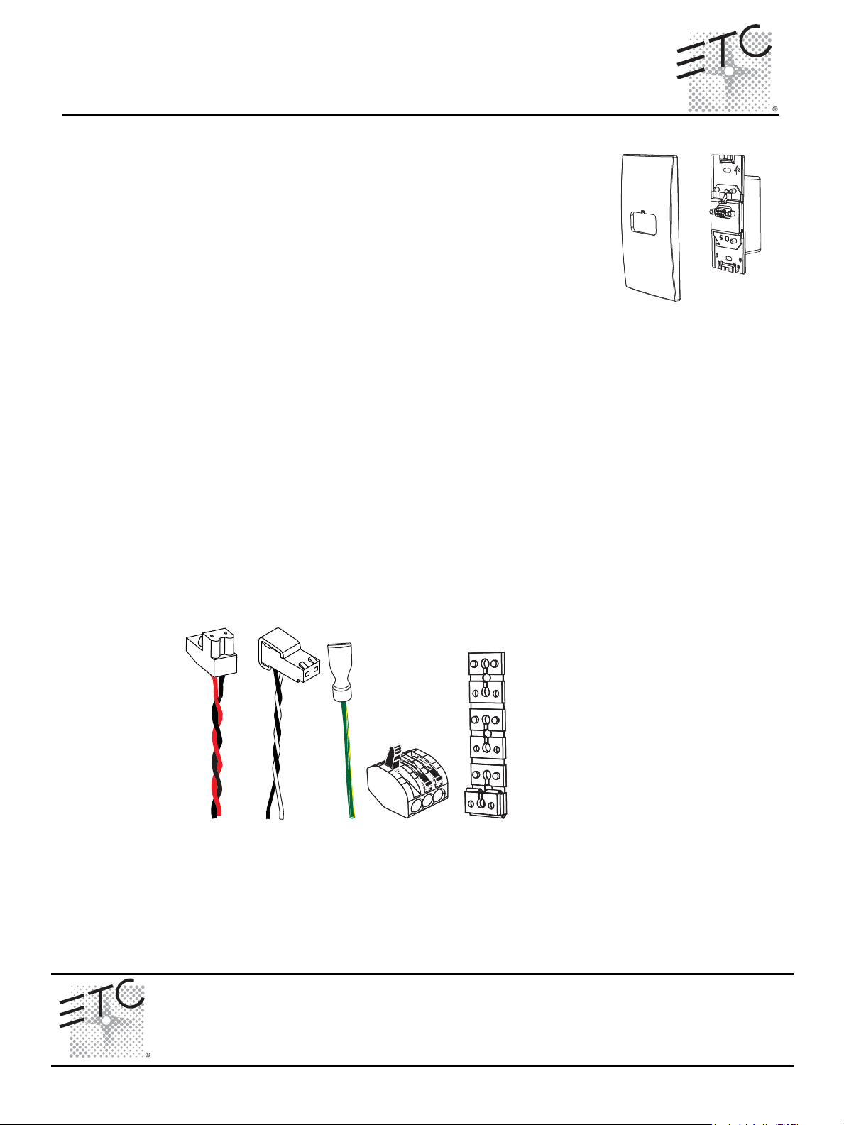
LinkPower
pigtail
Ground
pigtail
WAGO
Spacers
Auxiliary
Power pigtail
Unison® Heritage AV/Serial Interface Station
Overview
The Unison Heritage AV/Serial Interface station (model# UH1AV) provides a
method for any RS232 capable device to control and interact with the Unison
Paradigm LinkConnect control network. The AV/Serial Interface Station acts
as a virtual station with similar functionality to existing Heritage station types
allowing for virtual buttons, faders and rates to be manipulated with serial
commands.
Installation
The AV/Serial Interface Station may be installed into an industry standard
single gang backbox (provided by others) or a single gang surface mounted
backbox (sold separately and available from ETC).
Installation should follow local codes and standard practices. All control wiring should be installed and
terminated by a qualified installer and should follow standard wiring installation practices. Leave
approximately 10 inches (254mm) of wiring in the backbox for connection and future service needs.
AV/Serial Interface wiring requirements include:
• Connection to the Echelon
®
LinkPower® (LinkConnect) control network utilizing low voltage
Class II wiring. Wiring is topology free and polarity independent over Belden 8471 (or
approved equal).
• Connection of two 16 AWG (1.5mm
• Connection of one 14 AWG (2.5mm
2
) wires for 24 Vdc Auxiliary Power.
2
) ESD drain (ground) wire. Required only when the
control cable is not installed in grounded metal conduit.
The AV/Serial Interface station ships with a termination kit containing a LinkPower pigtail, Auxiliary
Power pigtail, ground wire pigtail, spacers, and all required connectors for installation.
Unison® Heritage AV/Serial Interface Station Page 1 of 3 Electronic Theatre Controls, Inc.
Corporate Headquarters
London, UK
Rome, IT
Holzkirchen, DE
Hong Kong Rm 1801, 18/F, Tower 1 Phase 1, Enterprise Square, 9 Sheung Yuet Road, Kowloon Bay, Kowloon, Hong Kong Tel +852 2799 1220 Fax +852 2799 9325
Service:
Web:
7181M2120
Unit 26-28, Victoria Industrial Estate, Victoria Road, London W3 6UU, UK Tel +44 (0)20 8896 1000 Fax +44 (0)20 8896 2000
Via Ennio Quirino Visconti, 11, 00193 Rome, Italy Tel +39 (06) 32 111 683 Fax +44 (0) 20 8752 8486
(Americas) service@etcconnect.com
www.etcconnect.com
Rev A Released 10/2008
3031 Pleasant View Road, P.O. Box 620979, Middleton, Wisconsin 53562-0979 USA Tel +608 831 4116 Fax +608 836 1736
Ohmstrasse 3, 83607 Holzkirchen, Germany Tel +49 (80 24) 47 00-0 Fax +49 (80 24) 47 00-3 00
Copyright © 2008 ETC. All Rights Reserved. Product information and specifications subject to change.
(UK) service@etceurope.com (DE) techserv-hoki@etcconnect.com
(Asia) service@etcasia.com
ETC Installation Guide
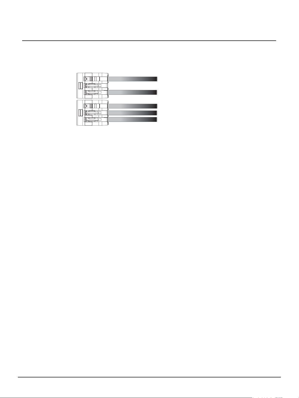
topology of a single
station installation
topology of multiple
stations installed in
series
installed control wire
pigtail wire
installed control wire
installed control wire to next station
pigtail wire
Connect the Wiring
AV/Serial Interface Station
Step 1: Pull all required wiring to the backbox .
Step 2: Terminate and connect LinkPower. LinkPower is topology free and polarity independent.
You may install LinkPower in any combination of bus, loop, star or home-run.
a: Locate the LinkPower pigtail and two WAGO cage clamp connectors from the termination
kit.
b: Strip 3/8” (9-10mm) from the ends of each LinkPower wire (both pigtail and installed
LinkPower wire).
c: Use the WAGO cage clamp connector to connect the installed control wire to the
connectorized pigtail wires provided. Open the terminal levers on the WAGO connector
and insert the installed (typically black) Belden 8471 LinkPower wire and the black lead
from the LinkPower pigtail into the terminals.
d: Close the levers onto the wires.
e: Repeat for the installed (typically white) Belden 8471 LinkPower wire and remaining pigtail
wire using a new WAGO connector.
f: Install the LinkPower connector to J4 (NET) on the AV/Serial Interface control board.
Step 3: Terminate and connect Auxiliary Power (24 Vdc) wiring.
a: Locate the Auxiliary Power pigtail and two WAGO cage clamp connectors from the
termination kit.
b: Strip 3/8” (9-10mm) from the ends of each Auxiliary wire (both the provided pigtail and
installed wire).
c: Use the WAGO cage clamp connector to connect the installed power wire to the
connectorized pigtail wires provided. Open the terminal levers on the WAGO connector
and insert the installed (typically black) 16 AWG (1.5mm2) Auxiliary Power wire and the
black lead from the pigtail into the terminals.
d: Close the levers onto the wires.
e: Repeat for the installed (typically red) 16 AWG (1.5mm2) Auxiliary Power wire and
remaining pigtail wire using a new WAGO connector.
f: Install the Auxiliary connector to J3 (Power) on the AV/Serial Interface control board.
Step 4: Terminate the ESD drain (ground) wire. This connection is required only when the control
cable is not installed in grounded metal conduit.
a: Locate the ground wire pigtail and one WAGO cage clamp connector from the termination
kit.
a: Strip 3/8” (9-10mm) from the end of each ground wire (both the provided pigtail and the
installed wire).
b: Use the WAGO cage clamp connector to connect the installed ground wire to the pigtail
wire provided. Open the terminal levers on the WAGO connector and insert the installed
(typically green/yellow) ESD drain (ground) wire and the green/yellow lead from the pigtail
into the terminals.
c: Close the levers onto the wires.
d: Install the ground spade to the receptacle on the AV/Serial Interface Station control board.
Unison® Heritage AV/Serial Interface Station Page 2 of 3 Electronic Theatre Controls, Inc.
 Loading...