

Page 1
ETC® Installation Guide
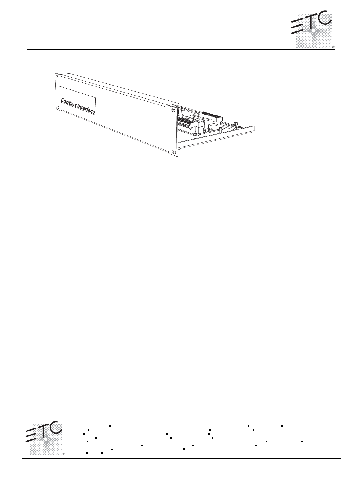
Unison® Heritage Rack Mount Contact Interface
Overview
This guide includes instruction for installation of the Unison Heritage Rack Mount Contact Interface.
The Rack Mount Contact Interface (model# UHCI-RM) provides convenient interface and integration to
external devices by sending and receiving contact closures. Up to eight switch input and relay output
connections are provided. Closures are configurable for either maintained or momentary operation.
Product Specification
• Dry contact inputs with no voltage applied.
• Dry contact outputs consist of Normally-Open (NO) 2 pole contact closu
1 amp at 28 Vdc, .5A at 120 VAC.
• Relay outputs are capable of switching resistive or inductive loads.
• Inputs and outputs are configurable in the Paradigm configuration using LightDesigner software.
• Contact inputs support up to 1,000 feet (305m) of 16 AWG (1.5mm
common.
re outputs, rated up to
2
) wire between input and
Unison
Installation Requirements
• Installs in a 19” rack mount enclosure utilizing two (E.I.A.) rack units.
• Thermal requirements:
• Ambient room temperature of 0-40°C (32-104°F) with an ambient humidity of 30-90%, non-
condensing.
Corpora te Headquarters
London, UK
Rome, IT
Holzkir chen , DE
Hong Kon g
Service:
Web:
7181M211 2
®
Unit 26-28, Vi ctoria Industrial Estate, Victoria Road, London W3 6UU, UK Tel +44 (0)20 88 96 1000 Fax +44 (0)20 8896 20 00
Via Ennio Quirino Visconti, 11, 00193 Rome, Italy Tel +39 (06) 32 111 683 Fax +4 4 (0) 20 8752 8486
Rm 1801, 18/F, Tower 1 Ph ase 1, Enterpr ise Square, 9 Sheung Yuet Road, Kowloon Bay, Kowloon, Hong Kon g Tel +852 2799 122 0 Fax +852 2799 9325
(Amer icas) service@e tcconnect.com (UK) service@etceur ope.com (DE) techserv-ho ki@etcconnect.co m (Asia) service@etcasia.com
www.etcconnect.com
Rev A Releas ed 11/20 08
3031 P leasant View Road, P.O. Box 620979 , Middleton, Wisconsin 53562-0 979 USA Tel +608 831 411 6 Fax +608 836 1736
Ohms trasse 3, 83607 Holzkirc hen, Germa ny Tel +49 (80 24) 47 00-0 Fa x +49 (80 24 ) 47 00-3 00
Copyright © 2008 ETC. All Rights Reserve d. Product inf ormation and specifications subject to change.
ETC intends this d ocument to be provided in its entirety.
.cnI ,slortnoC ertaehT cinortcelE3 fo 1 egaPecafretnI tcatnoC tnuoM kcaR egatireH
Page 2
ETC Installation Guide
Wire Requirements and Specification
Purpose Wire Type Notes
Interface Series
Link Power
(LinkConnect)
control network
Auxiliary power
(24 Vdc)
Chassis Ground 18 - 10 AWG
Contact Input and
Contact Output
terminals
Terminate Wiring
on control PCB
factory wiring
to Aux power
on control PCB
factory wiring
to LinkPower
Belden 8471
(or approved equal)
(2) 18 -10 AWG
(0.75 - 6mm
(0.75-6mm
2
)
2
)
24 - 12 AWG
(0.2 - 2.5mm
2
)
Echelon
®
LinkPower® (LinkConnect) control network utilizes low voltage Class II wire.
Wiring is topology free, polarity independent with a
maximum total system length of 1,640 feet (500m).
Required when wiring is not installed in grounded
metal conduit.
Two wires are required per switch (switch in or
switch out and common). Supports up to 1,000 feet
(305m) of 16 AWG (1.5mm
2
) between input and
common.
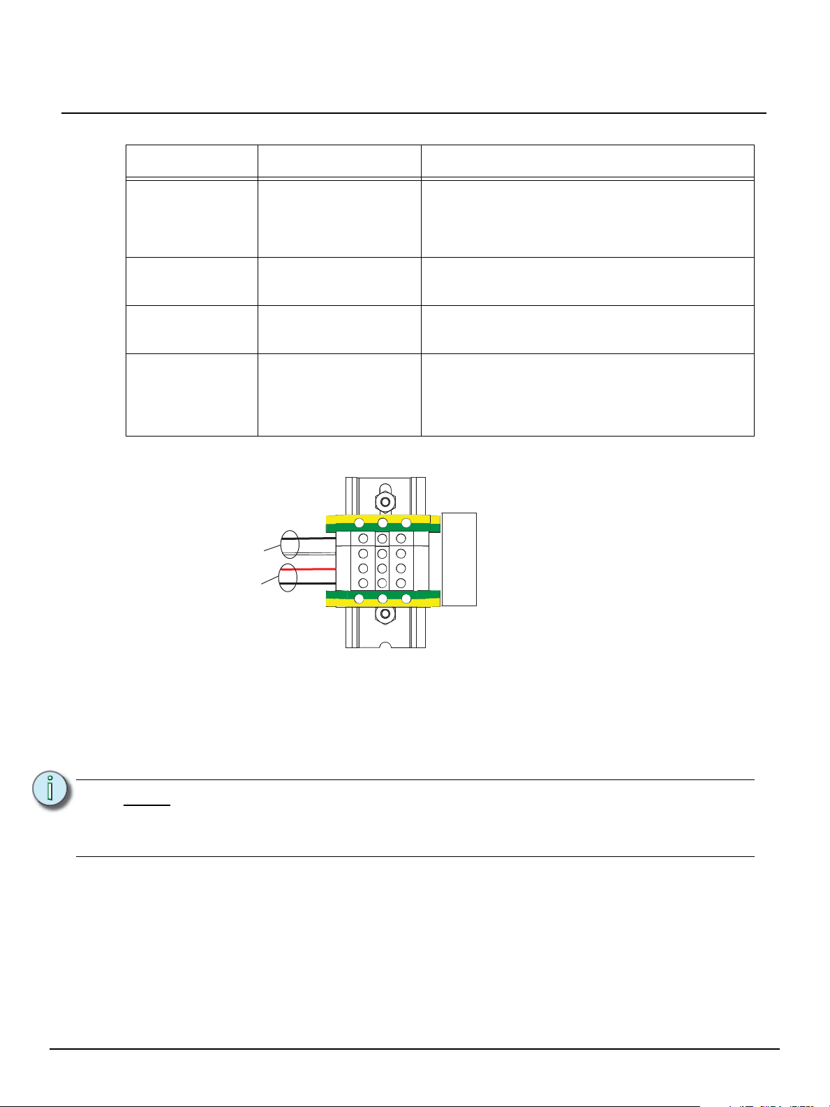
Ground
ULPULP+
+24VDC
Common
Ground
Step 1: Terminate LinkPower.
a: Strip 7/16” (11mm) from the ends of each LinkPower wire (typically black and white
twisted pair).
b: Using a jewelers screwdriver, open the ULP+ and ULP- terminals.
c: Insert the (typically white) wire from the pair into the ULP+ terminal.
d: Insert the (typically black) wire from the pair into the ULP- terminal.
Note:
LinkPower is topology free and polarity independent. You can install your LinkPower
wiring in any combination of bus, star, loop, or home-run. If more than one pair of
LinkPower wires are to be terminated be sure to label each pair individually. Each ULP
terminal can accept up to two conductors per terminal.
e: Tighten each terminal screw firmly to secure the wires in place.
Step 2: Terminate Auxiliary power (24 Vdc) wiring.
a: Strip 7/16” (11mm) from the ends of each Auxiliary power wire (typically a 16 AWG
black and red twisted pair).
b: Using a jewelers screwdriver, open the +24 VDC and Common terminals.
c: Insert the (typically red) wire from the pair into the+ 24 VDC terminal.
d: Insert the (typically black) wire from the pair into the Common terminal.
e: Tighten the terminal screw to secure the wire(s) in place.
Unison® Heritage Rack Mount Contact Interface Page 2 of 3 Electronic Theatre Controls, Inc.
Page 3

ETC Installation Guide
NC. NO.COM
NC.
NO. COM
NC.
NO. COM NC. NO.
COM
1234
NC. NO.COM
NC.
NO. COM
NC.
NO. COM NC. NO.
COM
5678
12345678
Contact Inputs
COM
factory wiring
to input
terminals
Contact Outputs
1 - 4
Contact Outputs
5 - 8
Contact Inputs
1 - 8 plus
Commons
Step 3: Terminate chassis ground.
a: Strip 7/16” (11mm) from the end of each chassis ground wire.
b: Loosen the terminal screw on a green/yellow terminal block. The green/yellow
terminal blocks are located at both ends of the terminal strip.
c: Insert the ground wire and tighten the screw firmly onto the wire.
Step 4: Terminate contact wires. All contact input and output terminations are made to the
removable pluggable connectors on the control PCB. When terminating a switch to a
Contact Interface, each pair of terminations, either Switch In or Switch Out, requires one
switch and one common connection.
Interface Series
Note:
There are only two Common terminals available for Contact Inputs and each Common
terminal allows up to two conductors. Additional connections should be bussed
together to share the line using WAGO CAGE CLAMP
®
connectors as required.
Unison® Heritage Rack Mount Contact Interface Page 3 of 3 Electronic Theatre Controls, Inc.
a: Strip 1/4” (7mm) from the ends of each wire.
b: Remove the connector from the control PCB.
c: Loosen the terminal screw for each required termination.
d: Insert the wires into the corresponding terminal block number and tighten the screws
firmly onto the wires.
 Loading...