

Page 1
ETC® Installation Guide
Unison® Heritage Contact and Fader Interface
Overview
This guide includes instruction for installation of the Unison Heritage Contact Interface and Unison
Heritage Fader Interface.
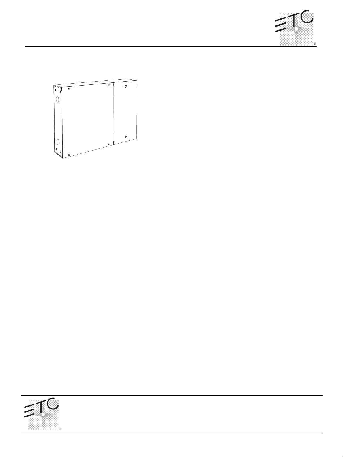
The Unison Heritage Contact Interface (model# UHCI) provides
convenient interface and integration to external devices by sending
and receiving contact closures. The interface enclosure provides
up to eight switch input and relay output connections. Closures are
configurable for either maintained or momentary operation.
The Unison Heritage Fader Interface (model# UHFI) provides
interface to external devices, such as faders or sensors, through a
variable 0-3.3 Vdc analog signal. The interface enclosure consists
of eight fader input connections and eight output lamp-driver
connections.
Product Specification
Installation Requirements
• Surface mount using the mounting keyholes provided.
• Thermal requirements
• Ambient room temperature of 0-40°C (32-104°F) with an ambient humidity of 30-90%, noncondensing.
• Wiring requirements:
• Connect to the Echelon
Class II wiring. Wiring is topology free and polarity independent over Belden 8471 (or
approved equal).
• Connect two 16 AWG (1.5mm
• Connect one 18-10 AWG (0.75-6mm
• Switch terminals accept 18-10 AWG (0.75-6mm
®
LinkPower® (LinkConnect) control network utilizing low voltage
2
) wires for 24 Vdc Auxiliary Power.
2
) ESD drain (ground) wire.
2
).
Contact Interface
• Dry contact inputs with no voltage applied.
• Dry contact outputs consist of Normally-Open (NO) 2 pole contact closure outputs, rated up to 1
amp at 28 Vdc, .5A at 120 VAC.
• Relay outputs are capable of switching up to eight resistive or inductive loads.
• Inputs and outputs are configurable in the Paradigm configuration using LightDesigner software.
• Contact inputs support up to 1,000 feet (305m) of 16 AWG (1.5mm
2
) wire between input and
common.
Fader Interface
• Enclosure provides eight fader input connections and to eight lamp-driver outputs.
• Fader supply voltage is +3.3 Vdc. Each fader input requires signal between 3.3 Vdc and 0 Vdc.
• Each lamp driver output provides 100mA at 24 Vdc.
• Lamp outputs support 1,000 feet (305m) of 16 AWG (1.5mm
Corporate Headquarters
London, UK
Rome, IT
Holzkirchen, DE
Hong Kong Rm 1801, 18/F, Tower 1 Phase 1, Enterprise Square, 9 Sheung Yuet Road, Kowloon Bay, Kowloon, Hong Kong Tel +852 2799 1220 Fax +852 2799 9325
Service:
Web:
7181M2110
Unison® Heritage Contact and Fader Interface Page 1 of 4 Electronic Theatre Controls, Inc.
Unit 26-28, Victoria Industrial Estate, Victoria Road, London W3 6UU, UK Tel +44 (0)20 8896 1000 Fax +44 (0)20 8896 2000
Via Ennio Quirino Visconti, 11, 00193 Rome, Italy Tel +39 (06) 32 111 683 Fax +44 (0) 20 8752 8486
(Americas) service@etcconnect.com
www.etcconnect.com
Rev A Released 10/2008
3031 Pleasant View Road, P.O. Box 620979, Middleton, Wisconsin 53562-0979 USA Tel +608 831 4116 Fax +608 836 1736
Ohmstrasse 3, 83607 Holzkirchen, Germany Tel +49 (80 24) 47 00-0 Fax +49 (80 24) 47 00-3 00
Copyright © 2008 ETC. All Rights Reserved. Product information and specifications subject to change.
(UK) service@etceurope.com (DE) techserv-hoki@etcconnect.com
2
) wire.
(Asia) service@etcasia.com
Page 2
ETC Installation Guide
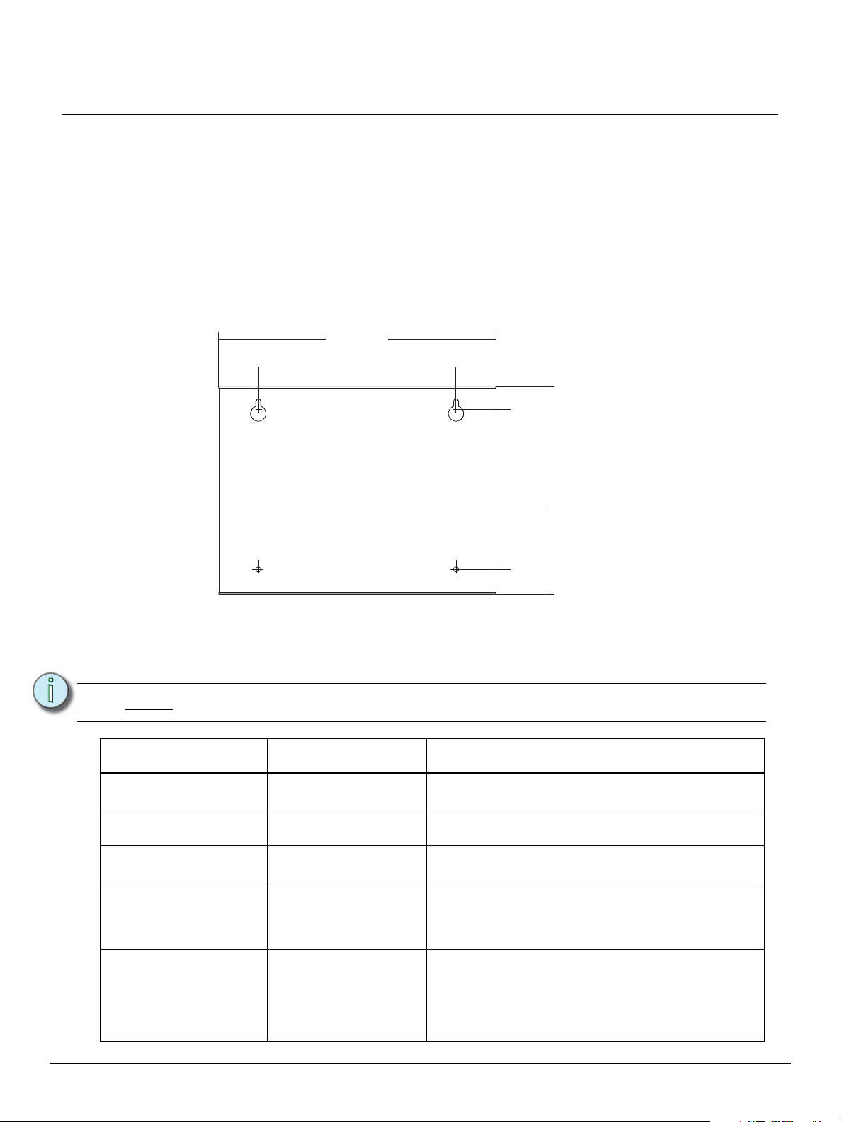
2”
(5.08cm)
14” (35.5 cm)
10.5”
(27cm)
12”
(30.5cm)
9.1”
(23.2cm)
1.25”
3.2 cm
Installation
Install the Enclosure
Step 1: Remove both covers from the enclosure to reveal the mounting keyholes.
a: The left cover is secured with four screws.
b: The right cover is secured with two 3/4 turn fasteners.
Step 2: Using the keyhole measurements in the graphic below, predrill and install two 1/4” (6mm)
bolts (bolts not provided).
Step 3: Install the enclosure onto the mounting bolts and secure.
Step 4: Notice the two screw holes on the bottom right and left of the rear panel. Use two screws
(not provided) to secure the enclosure the wall.
Interface Series
Rough-in Conduit and Wire
Conduit knockouts are provided on the left and bottom sides of the enclosure for installation
convenience. Wiring and termination for each interface type, Heritage Contact Interface and Heritage
Fader Interface, are similar. Pull the required wiring into the enclosure.
Note:
Purpose Wire Type Notes
Link Power Belden 8471 (or
Auxiliary Power 24 Vdc
ESD drain (ground)
Contact Interface:
Switch In and Switch Out
terminals
Fader Interface:
Fader input and Lamp
output terminals
Low voltage control cables must be run in separate conduit from power wires.
Wiring is topology free, polarity independent with a
approved equal)
(2) 18 AWG (0.75mm2)
18-10 AWG (0.75-6mm
18-10 AWG (0.75-6mm
18-10 AWG (0.75-6mm
maximum total system length of 1,640 feet (500m).
2
Required when wiring is not installed in grounded metal
)
conduit.
2
Two wires are required per switch (switch in or switch out
)
and common). Supports up to 1,000 feet (305m) of 16
AWG (1.5mm
2
Three wires are required per fader input connection
)
(fader input, +3.3 Vdc and common). An additional two
wires are required for Lamp output (lamp output and V
out). Supports up to 1,000 feet (305m) of 16 AWG
(1.5mm
2
) between input and common.
2
).
Unison® Heritage Contact and Fader Interface Page 2 of 4 Electronic Theatre Controls, Inc.
Page 3

ETC Installation Guide
LinkPower
pigtail
Auxiliary
Power pigtail
WAGO
topology of a single
station installation
topology of multiple
stations installed in
series
installed control wire
installed control wire to next station
pigtail wire
installed control wire
pigtail wire
Terminate Wiring
Locate the termination kit shipped with the Interface packaging. This kit
includes a LinkPower pigtail, an Auxiliary Power pigtail and all required
connectors for use during installation.
Step 1: Terminate and connect LinkPower. LinkPower is topology
free and polarity independent. You may install LinkPower
in any combination of bus, loop, star or home-run.
a: Locate the LinkPower pigtail and two WAGO cage
clamp connectors from the termination kit.
b: Strip 3/8” (9-10mm) from the ends of each LinkPower
wire (both the provided pigtail and installed LinkPower
wire).
c: Use the WAGO cage clamp connector to connect the installed control wire to the
connectorized pigtail wires provided. Open the terminal levers on the WAGO
connector and insert the installed (typically black) Belden 8471 LinkPower wire and
the black lead from the LinkPower pigtail into the terminals.
d: Close the levers onto the wires.
e: Repeat for the installed (typically white) Belden 8471 LinkPower wire and remaining
pigtail wire using a new WAGO connector.
f: Install the LinkPower connector to J2 (NET) on the control board.
Interface Series
Unison® Heritage Contact and Fader Interface Page 3 of 4 Electronic Theatre Controls, Inc.
Step 2: Terminate and connect Auxiliary Power (24 Vdc) wiring.
a: Locate the Auxiliary Power pigtail and two WAGO cage clamp connectors from the
termination kit.
b: Strip 3/8” (9-10mm) from the ends of each Auxiliary wire (both the provided pigtail and
installed wire).
c: Use the WAGO cage clamp connector to connect the installed power wire to the
connectorized pigtail wires provided. Open the terminal levers on the WAGO
connector and insert the installed (typically black) 16 AWG (1.5mm
wire and the black lead from the pigtail into the terminals.
d: Close the levers onto the wires.
e: Repeat for the installed (typically red) 16 AWG (1.5mm
remaining pigtail wire using a new WAGO connector.
f: Install the Auxiliary connector, labeled “Power” (location J5 for Contact Interface and
J7 for the Fader Interface) on the control board.
Step 3: Terminate the ESD drain (ground) wire.
a: Strip 7/16” (11mm) from the end of the ground wire.
b: Loosen the terminal screw on a green/yellow terminal block. The green/yellow
terminal blocks are located at either end of the terminal strip. All field terminations
should be made to the right side of the terminal strip.
c: Insert the ground wire and tighten the screw onto the wire.
2
) Auxiliary Power
2
) Auxiliary power wire and
Page 4

ETC Installation Guide
COM2
SWITCH OUT
COM5
SW6 OUT
COM4
SW5 OUT
COM3
SW4 OUT
SW3 OUT
SW1 OUT
SW2 OUT
SWITCH IN
COM
SW8 IN
SW7 IN
SW6 IN
SW5 IN
SW4 IN
SW3 IN
SW2 IN
SW1 IN
COM
COM
COM
COM1
COM6
SW7 OUT
COM7
SW8 OUT
COM8
LAMPS FADER
+3.3 VDC
PT8
PT7
PT6
PT5
PT4
PT3
PT2
PT1
COM
V out
LP1
LP2
LP3
LP4
LP5
LP6
LP8
LP7
Contact
Interface
Fader
Interface
Step 4: Terminate contact / fader interface wires. All field terminations are made to the right side
of the terminal strip.
Interface Series
• When terminating a switch to a Contact Interface, each pair of terminations, either
Switch In or Switch Out, requires one switch and one common connection.
• When terminating a fader input to a Fader Interface, three wires are terminated
including a “PT” connection, “+3.3 Vdc” connection and a “Com” connection.
Note:
There is only one +3.3 Vdc terminal and one common (COM) terminal for fader inputs.
When multiple fader inputs are required, each terminal allows up to eight wires in the
single terminal. Additional connections can be bussed together to share the line using
WAGO connectors as required.
• When a lamp indication is required for the fader input (Fader Interface only), two
additional wires are required including an “LP” and a common (COM) connection.
Each lamp output terminal is functionally connected to a fader input terminal
(example: PT1 is factory wired and functionally connected to LP1).
Note:
The lamp voltage conducts from “V out” to the lamp outputs. When using polarity
sensitive indicators such as an LED, connect the anode to “V out” and the cathode to
the lamp “LP” connection.
a: Strip 7/16” (11mm) from the ends of each wire.
b: Loosen the terminal screw for each required termination.
c: Insert the wires into the corresponding terminal block number and tighten the screws
Unison® Heritage Contact and Fader Interface Page 4 of 4 Electronic Theatre Controls, Inc.
firmly onto the wires.
 Loading...