

Page 1
ETC Installation Guide
LinkPower
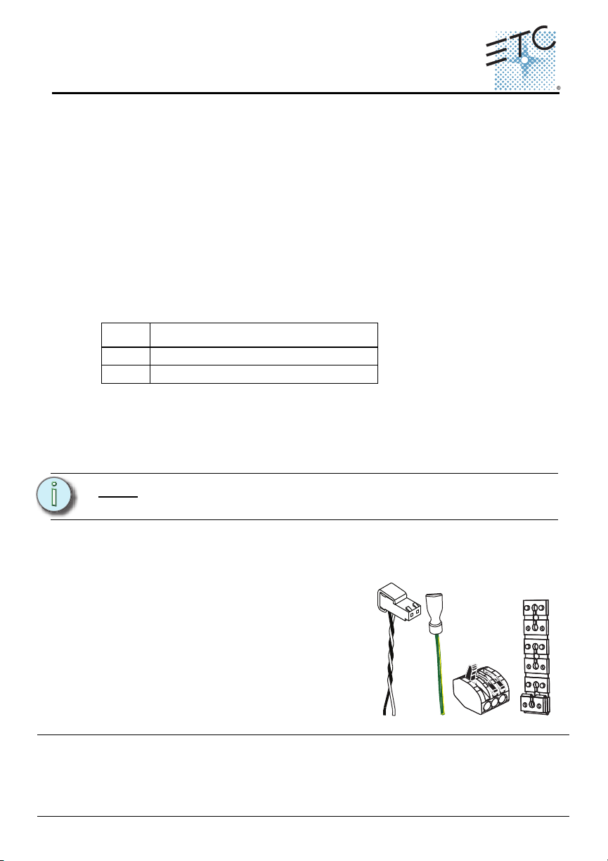
pigtail
Ground
pigtail
WAGO
Spacers
Unison Heritage Button Station
Overview
The Unison® Heritage Button Station connects to the LinkConnect station
communication bus. LinkConnect is based on Echelon® LonWorks™ with
LinkPower bidirectional protocol, and uses one pair of wires (data+, data–).
LinkPower is topology free and polarity independent; you can install your
LinkPower data runs in any desired combination of bus, star, loop, and home-run.
ETC recommends using Belden 8471 (or approved equal) wire. The total
combined length of a LinkPower wire run may not exceed 1,640 feet (500m), with
a maximum distance of 1,312 feet (400m) between any two devices. The Heritage
Button Station may be installed into an industry standard single gang backbox
(provided by others) or a surface mounted backbox (sold separately and available
from ETC).
Heritage Button Station Surface Backbox
Model Description
-1S Unison 1Gang surface mount backbox
-2S Unison 2Gang surface mount backbox
All control wiring should be installed and terminated by a qualified installer and
should follow standard wiring installation practices. Leave approximately 10 inches
(254mm) of wiring in the backbox for connection and to allow slack for future
service needs.
Note:
ETC requires that all stations be grounded by using grounded
metal conduit or a 14 AWG (2.5mm2) ESD drain wire.
Installing the Heritage Button Station
Installation should follow local codes
and standard practices. The backbox
should be installed square for best
results. Ensure that the backbox is clean
and free of obstructions and that all
wiring is installed correctly.
Heritage stations ship with a termination
kit containing a LinkPower pigtail, a
ground wire pigtail, spacers, and all
Corporate Headquarters
London, UK
Rome, IT
Holzkirchen, DE
Hong Kong Rm 1801, 18/F, Tower 1 Phase 1, Enterprise Square, 9 Sheung Yuet Road, Kowloon Bay, Kowloon, Hong Kong Tel +852 2799 1220
Service:
Web:
7181M2100
required connectors for installation.
Unit 26-28, Victoria Industrial Estate, Victoria Road, London W3 6UU, UK Tel +44 (0)20 8896 1000 Fax +44 (0)20 8896 2000
Via Pieve Torina, 48, 00156 Rome, Italy Tel +39 (06) 32 111 683 Fax +44 (0)20 8752 8486
(Americas) service@etcconnect.com
www.etcconnect.com
Rev D Released 2012-02 ETC intends this document to be provided in its entirety.
3031 Pleasant View Road, P.O. Box 620979, Middleton, Wisconsin 53562-0979 USA Tel +608 831 4116 Fax +608 836 1736
Ohmstrasse 3, 83607 Holzkirchen, Germany Tel +49 (80 24) 47 00-0 Fax +49 (80 24) 47 00-3 00
Copyright © 2012 ETC. All Rights Reserved. Product informati on and specifications subject to change.
(UK) service@etceurope.com (DE) techserv-hoki@etcconnect.com
(Asia) service@etcasia.com
Unison Heritage Button Station Page 1 of 4 Electronic Theatre Controls, Inc.
Page 2
ETC Installation Guide
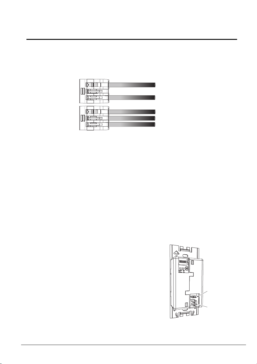
Topology of a
single station
installation
Topology of
multiple stations
installed in series
Installed control wire
Pigtail wire
Installed control wire
Installed wire to next station
Pigtail wire
Ground
spade
LinkPower
connector
Connecting the Wiring
Step 1: Pull all required wiring to the backbox.
Step 2: Terminate and connect LinkPower. LinkPower is topology free and
polarity independent. You may install LinkPower in any combination
of bus, loop, star, or home-run.
a: Locate the LinkPower pigtail and two WAGO CAGE CLAMP
connectors from the termination kit.
b: Strip 3/8” (9-10mm) from the ends of each LinkPower wire
(both pigtail and installed LinkPower wire).
c: Use the WAGO CAGE CLAMP connector to connect the
installed control wire to the connectorized pigtail wires
provided. Open the terminal levers on the WAGO connector
and insert the installed (typically black) Belden 8471
LinkPower wire and the black lead from the LinkPower pigtail
into the terminals.
d: Close the levers onto the wires.
e: Repeat for the installed (typically white) Belden 8471
LinkPower wire and remaining pigtail wire using a new WAGO
connector.
f: Install the LinkPower connector onto the Heritage Button
Station control board.
Unison Heritage Series
®
Unison Heritage Button Station Page 2 of 4 Electronic Theatre Controls, Inc.
Step 3: Terminate the ESD drain (ground)
wire. This connection is required
only when the control cable is not
installed in grounded metal conduit.
a: Locate the ground wire pigtail
and one WAGO CAGE CLAMP
connector from the termination
kit.
b: Strip 3/8” (9-10mm) from the
end of each ground wire (both
the provided pigtail and the
installed wire).
Page 3
ETC Installation Guide
1
3
2
4
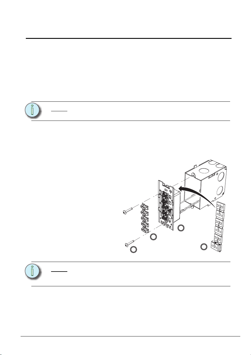
Step 1: Insert the station
electronics and
wiring into the
backbox. The
arrow on the
mounting plate
must point up.
c: Use the WAGO CAGE CLAMP connector to connect the
installed ground wire to the pigtail wire provided. Open the
terminal levers on the WAGO connector and insert the
installed (typically green/yellow) ESD drain (ground) wire and
the green/yellow lead from the pigtail into the terminals.
d: Close the levers onto the wires.
e: Install the ground spade onto the receptacle on the Heritage
Button Station control board.
Unison Heritage Series
Note:
A ground connection is required for all Heritage Button Station
assemblies if not installed in a grounded metal backbox.
Installing the Station into the Backbox
Spacers are provided to help align the station and cover flush against the wall
in flush mount applications. The spacers are not needed on surface mount
backboxes.
Note:
Unison Heritage Button Station Page 3 of 4 Electronic Theatre Controls, Inc.
Step 2: If needed, fold the receptacle spacer in a zig-zag fashion and press
Step 3: Secure the station with two screws. If using spacers, insert the
For some flush mount applications with certain trim rings it may
be necessary to remove the station’s back cover for installation
into the backbox.
together to achieve the required thickness to fill the gap between the
station and backbox. Cut off the excess and place between the
station and flush backbox.
screws through them.
Page 4
ETC Installation Guide
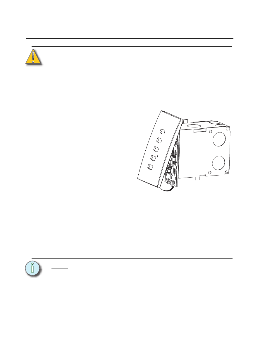
Step 1: Align the top of the
faceplate approximately
20 degrees from the
station.
Unison Heritage Series
CAUTION:
Step 4: Install the button caps so that the clear light tunnels protrude
through the caps.
To improve successful station and wall plate installation,
do not over tighten the screws. If screws are over
tightened, button activation can be negatively impacted.
Installing the Faceplate
The faceplate is secured to the station with two magnets that are located on
the bottom side of the faceplate.
Step 2: Hook the top of the faceplate to the tabs located on the station
electronics assembly. To ensure the faceplate is hooked properly on
the top hook, wiggle it slightly side to side while the bottom is angled
about 20 degrees from the wall.
Step 3: Swing the bottom of the faceplate down until the magnets engage.
Step 4: If the faceplate does not fully attach automatically, wiggle the bottom
of the plate until the magnets are seated properly to the station and
the faceplate is secure.
Note:
Unison Heritage Button Station Page 4 of 4 Electronic Theatre Controls, Inc.
The Paradigm Architectural Control Processor (P-ACP) to
which this Heritage station is connected must learn, or be told,
the station hardware address (a.k.a. neuron ID). This ID can be
manually entered into the configuration (as labeled on the
station metal) using LightDesigner software, or can be
identified by the connected Paradigm ACP using the "Connect
a Device" menu. Reference the Unison Paradigm Architectural
Control Processor Configuration Manual; specifically the
section on Arch Setup Menu, LonWorks Connections.
 Loading...