

ETC Unison Heritage Installation Manual
ETC Installation Guide
Unison Heritage Button Station
Unison Heritage Button Station Page 1 of 4 Electronic Theatre Controls, Inc.
Corporate Headquarters
3031 Pleasant View Road, P.O. Box 620979, Middleton, Wisconsin 53562-0979 USA Tel +608 831 4116 Fax +608 836 1736
London, UK
Unit 26-28, Victoria Industrial Estate, Victoria Road, London W3 6UU, UK Tel +44 (0)20 8896 1000 Fax +44 (0)20 8896 2000
Rome, IT
Via Pieve Torina, 48, 00156 Rome, Italy Tel +39 (06) 32 111 683 Fax +44 (0)20 8752 8486
Holzkirchen, DE
Ohmstrasse 3, 83607 Holzkirchen, Germany Tel +49 (80 24) 47 00-0 Fax +49 (80 24) 47 00-3 00
Hong Kong Rm 1801, 18/F, Tower 1 Phase 1, Enterprise Square, 9 Sheung Yuet Road, Kowloon Bay, Kowloon, Hong Kong Tel +852 2799 1220
Service:
(Americas) service@etcconnect.com
(UK) service@etceurope.com (DE) techserv-hoki@etcconnect.com
(Asia) service@etcasia.com
Web:
www.etcconnect.com
Copyright © 2012 ETC. All Rights Reserved. Product information and specifications subject to change.
7181M2100
Rev D Released 2012-02 ETC intends this document to be provided in its entirety.
Overview
The Unison® Heritage Button Station connects to the LinkConnect station
communication bus. LinkConnect is based on Echelon® LonWorks™ with
LinkPower bidirectional protocol, and uses one pair of wires (data+, data–).
LinkPower is topology free and polarity independent; you can install your
LinkPower data runs in any desired combination of bus, star, loop, and home-run.
ETC recommends using Belden 8471 (or approved equal) wire. The total
combined length of a LinkPower wire run may not exceed 1,640 feet (500m), with
a maximum distance of 1,312 feet (400m) between any two devices. The Heritage
Button Station may be installed into an industry standard single gang backbox
(provided by others) or a surface mounted backbox (sold separately and available
from ETC).
All control wiring should be installed and terminated by a qualified installer and
should follow standard wiring installation practices. Leave approximately 10 inches
(254mm) of wiring in the backbox for connection and to allow slack for future
service needs.
Installing the Heritage Button Station
Installation should follow local codes
and standard practices. The backbox
should be installed square for best
results. Ensure that the backbox is clean
and free of obstructions and that all
wiring is installed correctly.
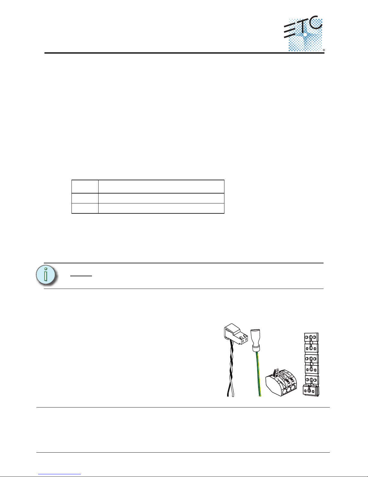
Heritage stations ship with a termination
kit containing a LinkPower pigtail, a
ground wire pigtail, spacers, and all
required connectors for installation.
Heritage Button Station Surface Backbox
Model Description
-1S Unison 1Gang surface mount backbox
-2S Unison 2Gang surface mount backbox
Note:
ETC requires that all stations be grounded by using grounded
metal conduit or a 14 AWG (2.5mm2) ESD drain wire.
LinkPower
pigtail
Ground
pigtail
WAGO
Spacers
ETC Installation Guide
Unison Heritage Series
Unison Heritage Button Station Page 2 of 4 Electronic Theatre Controls, Inc.
Connecting the Wiring
Step 1: Pull all required wiring to the backbox.
Step 2: Terminate and connect LinkPower. LinkPower is topology free and
polarity independent. You may install LinkPower in any combination
of bus, loop, star, or home-run.
a: Locate the LinkPower pigtail and two WAGO CAGE CLAMP
®
connectors from the termination kit.
b: Strip 3/8” (9-10mm) from the ends of each LinkPower wire
(both pigtail and installed LinkPower wire).
c: Use the WAGO CAGE CLAMP connector to connect the
installed control wire to the connectorized pigtail wires
provided. Open the terminal levers on the WAGO connector
and insert the installed (typically black) Belden 8471
LinkPower wire and the black lead from the LinkPower pigtail
into the terminals.
d: Close the levers onto the wires.
e: Repeat for the installed (typically white) Belden 8471
LinkPower wire and remaining pigtail wire using a new WAGO
connector.
f: Install the LinkPower connector onto the Heritage Button
Station control board.
Step 3: Terminate the ESD drain (ground)
wire. This connection is required
only when the control cable is not
installed in grounded metal conduit.
a: Locate the ground wire pigtail
and one WAGO CAGE CLAMP
connector from the termination
kit.
b: Strip 3/8” (9-10mm) from the
end of each ground wire (both
the provided pigtail and the
installed wire).
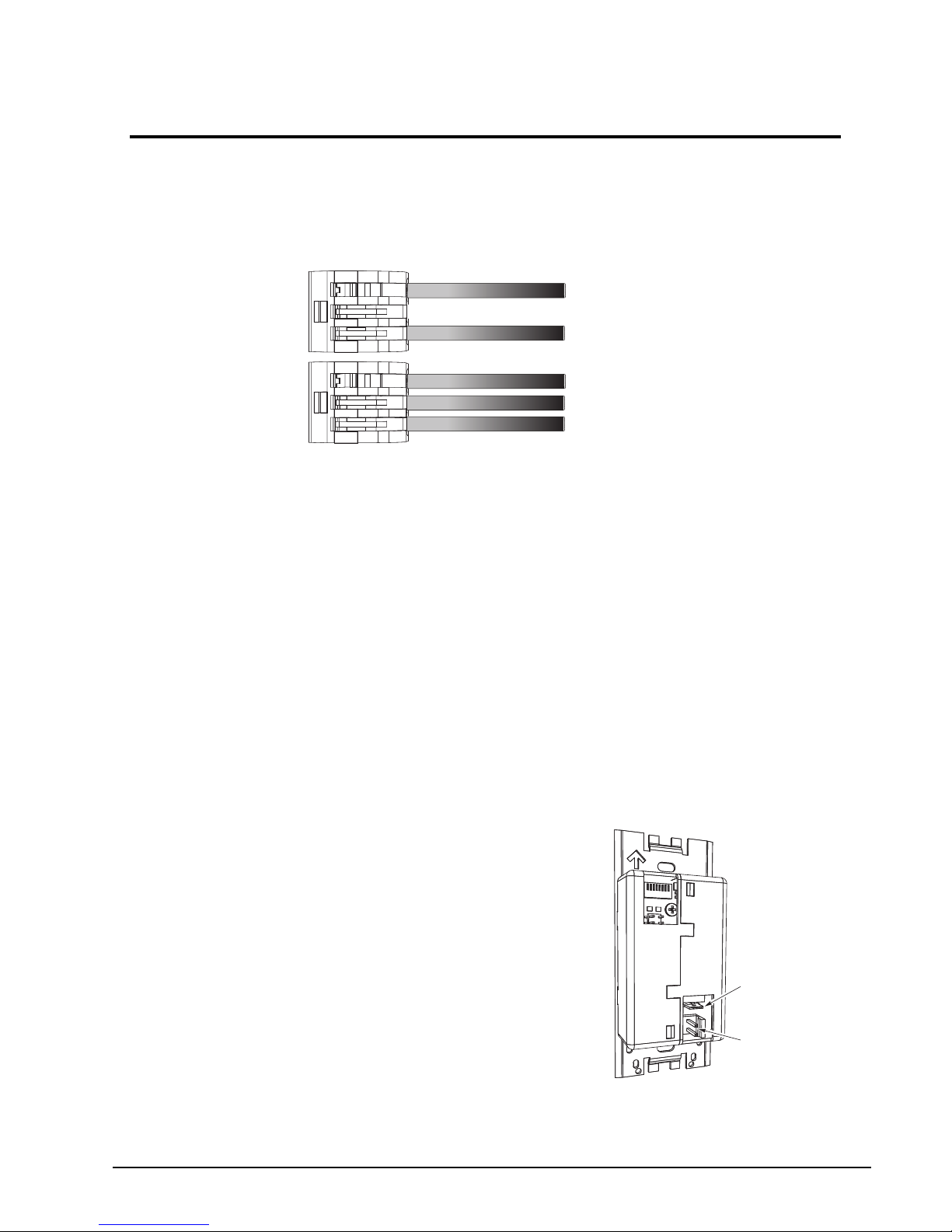
Topology of a
single station
installation
Topology of
multiple stations
installed in series
Installed control wire
Pigtail wire
Installed control wire
Installed wire to next station
Pigtail wire
Ground
spade
LinkPower
connector
 Loading...