

Page 1
ETC® Setup Guide
Step 2:
Step 3:
Step 4:
Unison® Fluorescent Option Kit Installation
.
Note:
A single Unison DRd rack supports the use of either the DALI option kit or the FLO
option kit, but not both in the same rack.
It is best to install rack options after conduit rough-in and the line, load and control terminations
are complete to reduce the likelihood of damage to the option board.
Fluorescent Option Kit
Install the Fluorescent Option Kit
The fluorescent option (DRd-FLO) kit provides 24 outputs for control of 4-wire (0-10 Vdc)
fluorescent ballasts. Each channel output is linked one - to - one with a rack circuit for power
control. The FLO board is comprised of 24 individual 0 - 10 Vdc connections, each rated to
control a maximum of 400mA per channel (typically 50 or more ballasts).
Each output connection is clearly labeled on the removable screw terminal bus connectors. The
removable connectors accept 12 - 24 AWG (4 - .25mm
2
) Class 1 wire.
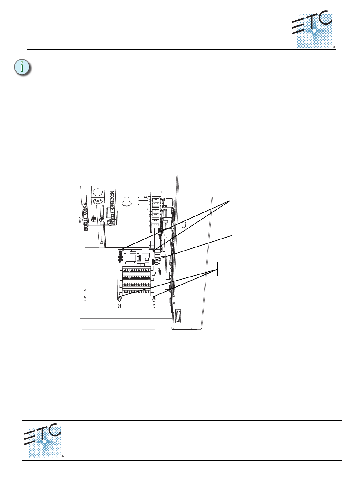
Step 1: Align the FLO option board to the mounting studs in the bottom of the DRd rack.
• Notice the mounting holes on the FLO option board. One is a slotted keyhole,
another is an open ended slot and the remaining two on the other end of the
board are standard mounting holes used to secure the board in place.
Step 2: Set the rear stud through the slotted keyhole and align the open ended slot with the
back right side mounting stud.
Step 3: Gently slide the FLO board toward the right I/O board aligning the five prong
connector to the receptacle on the right I/O board.
Step 4: Secure the remaining two mounting holes to the pems with the screws provided.
Corporate Headquarters
London, UK
Rome, IT
Holzkirchen, DE
Hong Kong Rm 1801, 18/F, Tower 1 Phase 1, Enterprise Square, 9 Sheung Yuet Road, Kowloon Bay, Kowloon, Hong Kong Tel +852 2799 1220 Fax +852 2799 9325
Service:
Web:
7183M2220
Unison Fluorescent Option Kit Setup Guide Page 1 of 2 Electronic Theatre Controls, Inc.
Unit 26-28, Victoria Industrial Estate, Victoria Road, London W3 6UU, UK Tel +44 (0)20 8896 1000 Fax +44 (0)20 8896 2000
Via Pieve Torina, 48, 00156 Rome, Italy Tel +39 (06) 32 111 683 Fax +44 (0) 20 8752 8486
(Americas) service@etcconnect.com
www.etcconnect.com
Rev C Released 2012-02 ETC intends this document to be provided in its entirety.
3031 Pleasant View Road, P.O. Box 620979, Middleton, Wisconsin 53562-0979 USA Tel +608 831 4116 Fax +608 836 1736
Ohmstrasse 3, 83607 Holzkirchen, Germany Tel +49 (80 24) 47 00-0 Fax +49 (80 24) 47 00-3 00
Copyright © 2012 ETC. All Rights Reserved. Product information and specifications subject to change.
(UK) service@etceurope.com (DE) techserv-hoki@etcconnect.com
(Asia) service@etcasia.com
Page 2
ETC Setup Guide
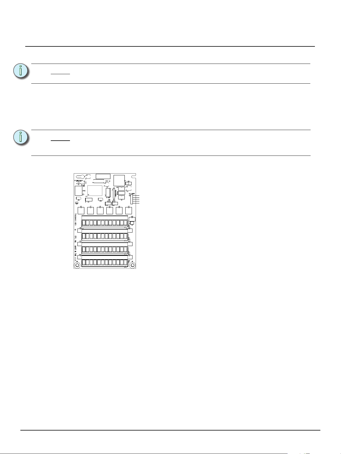
Each of the four bus connectors on the option board provide
termination for six fluorescent outputs. Each bus connector is
labeled for ease of identification and is pluggable for ease of
wiring termination. Terminals accept 12-24 AWG (4 - .25mm
2
)
Class 1 wire.
Connect Fluorescent Option Wiring
Unison® Fluorescent Option Kit
Note:
Note:
Fluorescent control wiring must be routed in separate conduit from the line voltage
wiring for 0-10V ballast.
To control 4-wire fluorescent ballasts, the power circuit in the rack must be a dimmer module
and assigned to 4-wire fluorescent dimmer mode. Reference the related architectural control
processor configuration manual for instruction to change dimmer mode.
It is important to label the 4-wire fluorescent load and control wiring sets with the circuit
designation. Control wires terminate on the associated FLO option board output terminal.
The associated output loop terminal number should always match the straight power
circuit numbering label inside the rack, regardless of straight or balanced rack dimmer
configuration.
Example: If circuit 1 is configured as a dimmer with a 4-wire fluorescent dimmer mode, ballast
control wiring would terminate to the FLO option board output terminals labeled “1”.
Label
-6+ -5+ -4+ -3+ -2+ -1+
2008
-12+ -11+ -10+ -9+ -8+ -7+
-18+ -17+ -16+ -15+ -14+ -13+
-24+ -23+ -22+ -21+ -20+ -19+
FLUOR 1 - 6
FLUOR 7 - 12
FLUOR 13 - 18
FLUOR 19 -24
Step 1: Pull fluorescent ballast control wiring pairs into the DRd rack enclosure per the wire
entry plan.
Step 2: Strip each wire pair back 1/4 inch (6mm).
Step 3: Remove the bus connector for fluorescent outputs 1-6. The pluggable connector is
seated tight in the receptacle. You may need to gently pry the connector free from
the board using a small jewelers screwdriver.
Step 4: Notice the connector is labeled for your reference during wire termination. Using a
jewelers screwdriver, loosen the terminals and insert each of the data “+” and
data “-” wires in the wire set into the appropriate terminal.
a: Terminate the violet (typical) control wire of the first pair into the “+” terminal
associated to the power circuit.
b: Terminate the gray (typical) control wire of the first pair into the “-” terminal
associated to the power circuit.
c: Tighten each screw terminal until the wire is held snug.
Step 5: Repeat steps 1 through 4 for the remaining fluorescent outputs through output 6.
Step 6: Replace the first bus connector to the FLO option board and repeat for the remaining
fluorescent outputs in the system (up to 24 outputs).
Unison Fluorescent Option Kit Setup Guide Page 2 of 2 Electronic Theatre Controls, Inc.
 Loading...