

ETC Unison Echo Preset Station User Manual
ETC Installation Guide
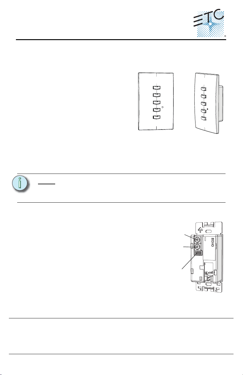
Address wheel
Space wheel
DIP switches
Echo Preset Station Installation
Overview
Echo preset stations are used to activate built-in presets in compatible power
control products.
Stations mount using a standard singlegang back box (RACO 690 or equivalent),
or an optional surface mount backbox
(ETC part number 7081A2004-1). Station
faceplates and buttons are available in
cream, ivory, grey, black and signal white.
Preset stations are provided with station
electronics, buttons, faceplate, a
termination kit, and installation hardware.
Installation Requirements
Preset station wiring uses (1) Belden 8471 and (1) 2.5mm2 (14 AWG) ESD ground
wire. Wiring is topology-free and may be bus, star, loop, home run or any
combination of these. Data wiring is limited to a total of 1640 feet (500 meters)
NEC Class 2 product to be wired in accordance to NEC Article 725 and local
jurisdiction requirements.
.
Note:
ETC requires that all stations be grounded by using grounded metal
conduit or a 14 AWG ESD drain wire. All control wiring should be
installed and terminated by a qualified installer and should follow
standard wiring installation practices.
Setting Station Functionality
Before installing, you must first assign an
address to the station and, if desired, adjust the
station’s functionality. Address is set using the
two numbered wheels on the rear of the station.
Functionality is set using the DIP switches found
just below the numbered wheels. The label on the
rear of the station identifies these components
and functions.
Setting the Address and Space
Station address is defined by the two numbered
wheels found on the back of the station. The top
address wheel defines the station address (1-16).
Corporate Headquarters
London, UK
Unit 26-28, Victoria Industrial Estate, Victoria Road, London W3 6UU, UK Tel +44 (0)20 8896 1000 Fax +44 (0)20 8896 2000
Rome, IT
Via Pieve Torina, 48, 00156 Rome, Italy Tel +39 (06) 32 111 683 Fax +44 (0)20 8752 8486
Holzkirchen, DE
Hong Kong Rm 1801, 18/F, Tower 1 Phase 1, Enterprise Square, 9 Sheung Yuet Road, Kowloon Bay, Kowloon, Hong Kong Tel +852 2799 1220
Service:
(Americas) service@etcconnect.com
Web:
www.etcconnect.com
7140M2110 Rev A Released 2013-03 ETC intends this document to be provided in its entirety.
Echo Preset Station Page 1 of 6 ETC, Inc.
3031 Pleasant View Road, P.O. Box 620979, Middleton, Wisconsin 53562-0979 USA Tel +608 831 4116 Fax +608 836 1736
Ohmstrasse 3, 83607 Holzkirchen, Germany Tel +49 (80 24) 47 00-0 Fax +49 (80 24) 47 00-3 00
Copyright © 2013 ETC. All Rights Reserved. Product information and specifications subject to change.
(UK) service@etceurope.com (DE) techserv-hoki@etcconnect.com
(Asia) service@etcasia.com

ETC Installation Guide
Echo Preset Station Installation
The bottom wheel defines the space which the station will control (also 1-16).
CAUTION:
Step 1: Set the space wheel to the appropriate number (1 thru 16) for the
Step 2: Set the address wheel to a unique number (1 thru 16) for the space.
Note:
Each station must have its station address set to a unique number (1-
16) for the space it controls. If two or more stations use the same
address for the same space, the system will not function properly.
space you want the station to control.
Total number of preset stations is limited by the power supply at the
host product. Refer to the host product documentation for the limits
specific to your system.
Setting Station Functionality
The bank of DIP switches found on the rear of the station can be set to alter
station functionality. Using a micro-tool you can slide the DIP switches up (On) to
activate them or down (Off) to deactivate. They are set to “OFF” by default.
The DIP switches have the following designations:
• DIP switch 1: “Use Off” - When set to on (up), the last button on the station
is set as an “OFF” command for the space. When set to off (down) the
button will activate a preset.
• DIP switch 2: “Custom Config” - for future development.
• DIP switch 3: “Disable IR Input” - When on (up), the infrared input for this
station will be disabled.
• DIP switch 8: “Restore Defaults”- When on (up), a “restore defaults at boot”
function is activated. Factory defaults can then be restored by:
a: disconnecting power from the station, then
b: reconnecting power to the station, then
c: resetting the DIP switch to down. This will prevent losing the
configuration in the event of a power loss.
All other DIP switches are unused.
Installing the Preset Station
Install Back Box
Step 1: Mount the back box using appropriate hardware for the surface you
are mounting to.
Step 2: Run conduit and wiring as required by the installation drawings.
Step 3: Leave a service loop of approximately 10” (254mm) of wiring in the
backbox.
Echo Preset Station Page 2 of 6 ETC, Inc.
ETC Installation Guide
Topology of a single
station installation
Topology of multiple
stations installed in
series
Installed control wire
Pigtail wire
Installed control wire
Installed wire to next station
Pigtail wire
Station power
pigtail
Ground
pigtail
WAGO
Ground
spade
Data
connector
Echo Preset Station Installation
Connect the Wiring
Step 4: Terminate and connect the station wiring.
a: Locate the data pigtail and two WAGO LeverLock connectors
found in the termination kit.
b: Strip 3/8” (9-10mm) from the
ends of each wire (both pigtail
and installed data wire).
c: Open the terminal levers on
the WAGO connector and
insert the Belden 8471 black
(-) lead wire and the black (-)
lead from the pigtail into the
terminals.
d: Close the levers onto the
wires, securing the
connection between the two.
e: Repeat this process for the Belden 8471 white (+) wire and
remaining white (+) pigtail wire using another WAGO connector.
f: Attach the connector onto the
preset station data connector.
Step 5: Terminate the ESD drain (ground)
wire.
a: Locate the ground pigtail and one
WAGO LeverLock connector from
the termination kit.
b: Strip 3/8” (9-10mm) from the end
of the ground wire and ground
pigtail.
c: Open the terminal levers on the
connector and insert the installed
(typically green/yellow) ESD drain
(ground) wire and the green/yellow lead from the pigtail into the
Echo Preset Station Page 3 of 6 ETC, Inc.
terminals.
d: Close the levers onto the wires, securing the connection between
the two.
 Loading...