

ETC Unison Echo Inspire Installation Manual
ETC Installation Guide
Unison Echo® Inspire® Station
Overview
Echo Inspire stations provide preset, zone, and space combine and color
controls for use with Unison Echo and Sensor® control systems.
Reference the ETC website at etcconnect.com for related Inspire station
documentation including the data sheet which provides a complete listing of
station types, and the Echo Inspire Station Programming Guide for complete
instruction to configure and program all station controls and features.
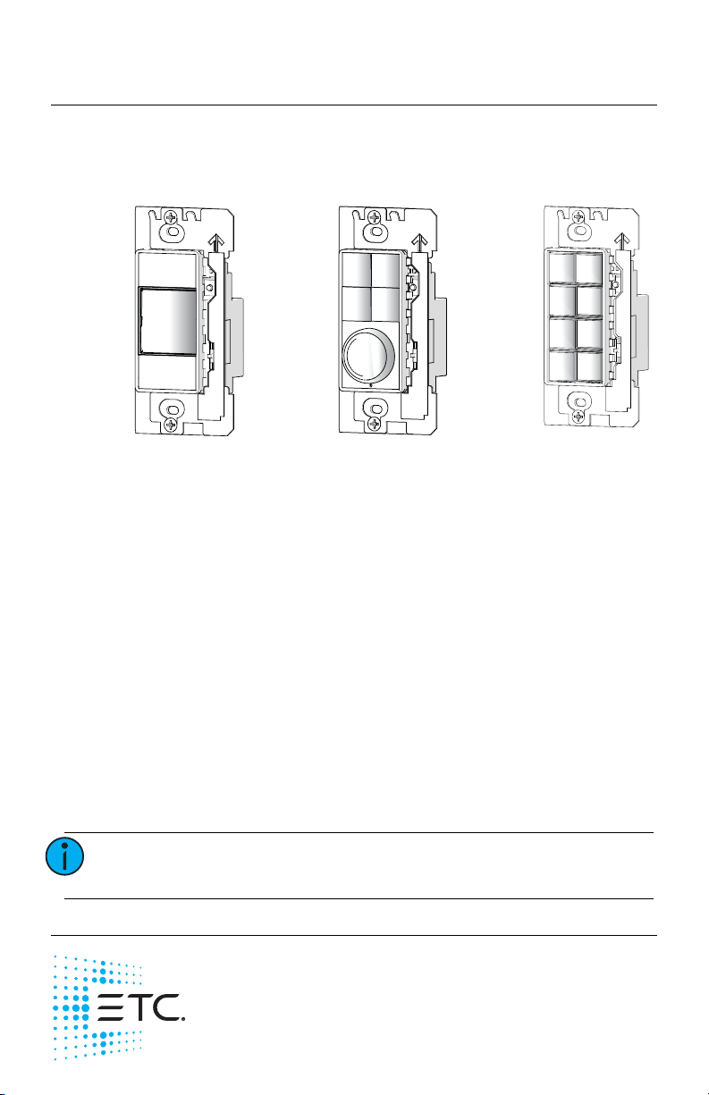
Stations are available in 1, 2, 4, 6, and 8 button assemblies, and a 4 button
with fader station. Station buttons are backlit by both blue and amber LEDs.
The 4 button with fader station knob is backlit with a blue LED.
Custom Configuration
This document guides you through the installation and local DIP switch setup
of the Echo Inspire station. For more detailed information about local
configuration options available for the Echo Inspire station, reference the
Echo Inspire Station Programming Guide.
For information about the custom configuration options available for the
Echo Inspire station using EchoAccess, reference the EchoAccess Mobile App
integrated help system. ETC’s user documentation is available from our
website etcconnect.com.
Note:
To configure the Echo Inspire station using EchoAccess,
the station Function switch must be set to Custom.
Corporate Headquarters Middleton, Wisconsin, USA Tel +608 831 4116
Service (Americas)
London, UK Tel +44 (0)20 8896 1000 Service: (UK) service@etceurope.com
Rome, IT
Holzkirchen, DE Tel +49 (80 24) 47 00-0 Service: (DE) techserv-hoki@etcconnect.com
Hong Kong
Web: etcconnect.com
specifications subject to change.
7186M2140 Rev E Released 2017-09
service@etcconnect.com
Tel +39 (06) 32 111 683 Service: (UK) service@etceurope.com
Tel +852 2799 1220 Service: (Asia) service@etcasia.com
© 2017 Electronic Theatre Controls, Inc.
ETC intends this document to be provided in its entirety.
Product information and

ETC Installation Guide
Inspire Station
Prepare for Installation
Echo Inspire stations ship with station electronics, a decorator style wall plate,
termination kit, and a template of standard button labels. The station may be
installed into an industry standard back box (provided by others) or surface
mounted back box (sold separately and available from ETC).
Inspire stations connect to the EchoConnect® station communication bus.
EchoConnect is a bidirectional protocol that uses one pair of wires (data+ and
data-) for both data and power. ETC recommends using Belden 8471 (or
approved equal) Class 2 wire.
The total combined length of an EchoConnect wire run (using Belden 8471,
or equal) may not exceed 1,640 feet (500m).
Note:
Note:
Environmental
• Indoor installation only - 0-50deg C, 5-95% non-condensing humidity
Installation
Installation should follow all local codes and standard electrical practices.
Note:
The back box should be installed plum and square for best results. Ensure that
the back box is clean and free of obstructions and that all wiring is installed
correctly.
Inspire stations ship with a termination kit for use with Belden 8471 (or
equivalent wire) and contains a power pigtail, a ground wire pigtail, spacers,
and all required wire termination connectors for installation.
All control wiring should be installed and terminated by
a qualified installer and should follow standard wiring
installation practices.
Leave approximately 10 inches (254mm) of wiring in the
back box for connection and to allow slack for future
service needs.
ETC requires that all stations be grounded. Pull an
additional 14 AWG (1.5mm2) wire for grounding when
control wires are not installed in grounded metal
conduit.
NEC Class 2 product to be wired in accordance to NEC
Article 725 and local jurisdiction requirements.
Echo Inspire Station Page 2 of 8 ETC

ETC Installation Guide
Inspire Station
Note:
When using Category5 (or equivalent) cable on the
EchoConnect communication bus, please note the
following:
- Not all topologies are supported using Cat5; careful
planning is required to ensure the proper termination
kits are available and the wire is pulled appropriately.
- Cat5 wiring may be terminated using EchoConnect
Cat5 Station Termination Kit and must be installed using
a bus topology. Refer to the installation guide that is
provided with the Cat5 Station Termination Kit
(7186A1207) for information to terminate Cat5 wiring.
Connect the Wiring
1: Pull all required wiring (data+, data-) into the back box. As needed,
pull an additional ESD ground wire (required only when the station is
not installed in grounded metal conduit).
2: Connect station ESD ground wire pigtail.
a: Strip 3/8” (9-10mm) of insulation from the ends of the station
ground wire pigtail, provided in the termination kit, and the
incoming ground wire.
b: Use one WAGO connector, provided in the termination kit, to
connect the station ESD ground pigtail and the incoming ground.
For stations using grounded metal conduit, connect the ground
pigtail to the metal backbox ground location.
c: Install the ESD ground wire pigtail Faston connector to the spade
terminal on the station electronics.
3: Terminate and connect EchoConnect wires. EchoConnect is topology
free, you may install the wires in any combination of bus, star, loop, or
home-run.
a: Strip 3/8” (9-10mm) from the ends of each power pigtail wire,
provided in the termination kit, and the installed control wires.
b: Use the provided WAGO connectors to connect the power pigtail
wires and the installed Belden 8471 control wires. One WAGO
should be used for the white wire pair (data +) and one for the
black wire pair (data -). Open the terminal levers on the WAGO
connector and insert the installed Belden 8471 wire and the lead
from the power pigtail into the terminals then close the levers.
c: Install the two pin connector from the power pigtail to the mating
receptacle on the station electronics.
Echo Inspire Station Page 3 of 8 ETC
 Loading...