

ETC Unison Echo Installation Manual
ETC Installation Guide
Unison Echo™ Wall Mount Station Power Supply w/ Aux Power
Station Power Supply with Auxiliary Power Page 1 of 4 Electronic Theatre Controls, Inc.
Corporate Headquarters Middleton, WI, USA Tel +608 831 4116 Service: (Americas) service@etcconnect.com
London, UK
Tel +44 (0)20 8896 1000 Service: (UK) service@etceurope.com
Rome, IT
Tel +39 (06) 32 111 683 Service: (UK) service@etceurope.com
Holzkirchen, DE
Tel +49 (80 24) 47 00-0 Service: (DE) techserv-hoki@etcconnect.com
Hong Kong
Tel +852 2799 1220 Service: (Asia) service@etcasia.com
Web: www.etcconnect.com
© 2015 ETC. All Rights Reserved. Product information and specifications subject to change.
7186M2104
Rev A Released 2015-06 ETC intends this document to be provided in its entirety.
Overview
The Echo Wall Mount Station Power Supply with Auxiliary
Power (E-SPM-WM-A) is designed for use with the Echo control
system to supply bus power for up to 16 Echo architectural
control stations on the topology-free EchoConnect control
network and provides 24 Vdc auxiliary power (maximum 36
watts) for Echo devices.
The E-SPM-WM-A also supports connection of up to 16
compatible power panels or distributed controllers over
EchoConnect.
For use with ETC Dimming and Relay Products.
Installation
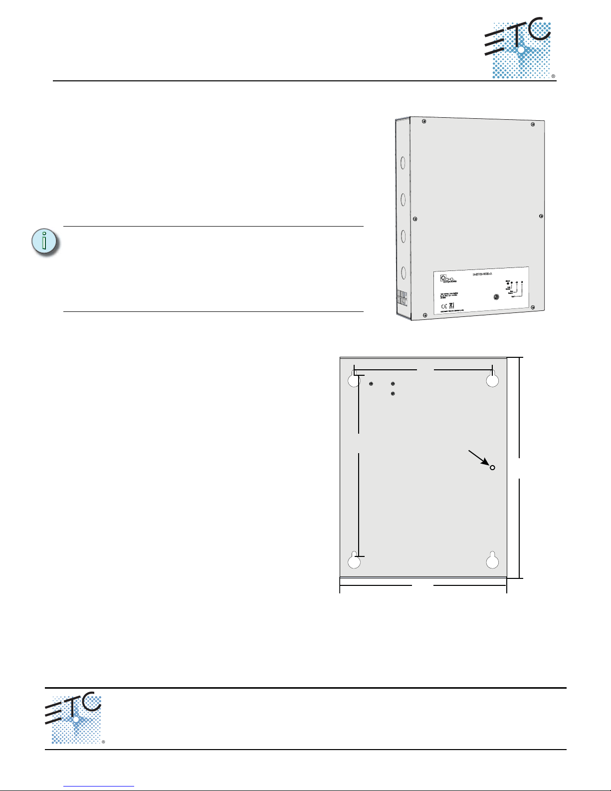
Mount the Enclosure to the Wall
Step 1: Remove the front cover of the enclosure
to reveal the four mounting keyholes.
Step 2: Align the enclosure to the wall and mark
the mounting keyholes. Alternatively,
use the measured keyhole dimensions
located in the graphic (right) to mark the
hole locations for the mounting
hardware.
Step 3: Drill the holes and install the mounting
hardware.
• Mounting hardware is not
supplied.
• Expose at least 1” (25mm) of
threads for mounting.
Step 4: Attach the enclosure to the mounting
hardware, where the back side is flush
to the wall, then tighten the mounting
hardware.
Step 5: Insert a screw into the provided wall anchor point, located between the left side mounting
keyholes of the enclosure. Populating this hole with a screw provides additional security that
the enclosure will not fall from the wall during a seismic condition.
Note:
If you are using Cat5 (or Cat5e) wiring, an
external Echo Cat5 Termination Box (is required.
Contact ETC for ordering details. Control wiring
instructions between the termination box and
this Wall Mount Station Power Supply with
Auxiliary Power are provided with the Cat5
termination box installation instructions.
10.5”
267mm
14”
356mm
insert seismic
condition screw
here
11. 5”
292mm
8.7”
221mm
3.15” deep
80mm
as viewed from the back panel
ETC Installation Guide
Wall Mount Station Power Supply with Auxiliary Power
Station Power Supply with Auxiliary Power Page 2 of 4 Electronic Theatre Controls, Inc.
Rough-In Conduit and Wiring
Knockouts are provided on top and bottom for conduit access into the enclosure. All wiring terminations
are accessible from the front of the enclosure with the cover removed.
Required terminations include -
• A single phase 115 VAC, 230 VAC, or 240 VAC power input (two wire) plus a protective Earth
(ground) wire, which terminates to the power input terminal block.
• EchoConnect and ESD Ground - Belden 8471 wire pair, plus one 14 AWG (2.5mm
2
) Echo station ESD
ground wire.
• 24 Vdc Auxiliary power, 16 AWG (1.5mm
2
) red and black wire pair.
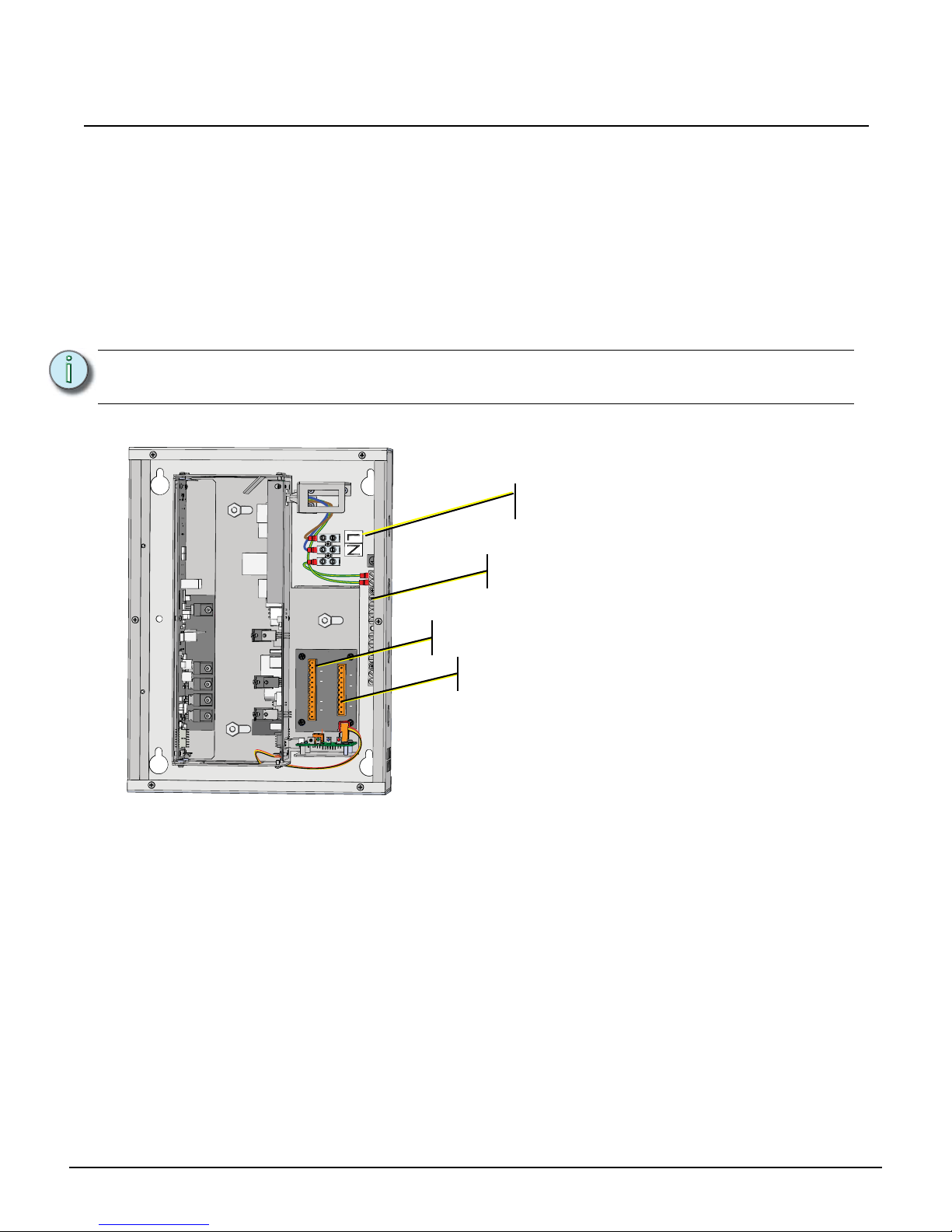
Terminate Wiring
Connect Power
Supply a single phase of 115 VAC or 230/240 VAC (2 wire plus ground) to the AC input terminals.
Step 1: Connect the Line (Hot) wire to the terminal labeled “L”.
Step 2: Connect the Neutral wire to the terminal labeled “N”.
Step 3: Connect the Protective Earth (ground) wire to the ESD ground terminal.
Step 4: Secure each connection firmly.
Note:
All low voltage Class II control cables must run in separate conduit from Class 1 power
wires.
- + - + - + - + - +
- +
- + - + - + - + - +
AC Input - 2 wire plus
Protective Earth (ground)
ESD Ground terminals - Echo station ESD
ground wires terminate here
EchoConnect station bus
24 Vdc Auxiliary power
 Loading...