

Page 1
ETC® Setup Guide
NO4
COM4
NO3
COM3
NO2
COM2
NO1
COM1
IN4
GND
IN3
GND
IN2
GND
IN1
GND
M1
M2
OUTPUTSINPUTS
J4 J5
7183B4605 REV
© 2008 ETC, INC.
MADE IN THE U.S.A.
M4
RS-232
J3
C2 C3 C4
CR1
CR2
CR3
CR4
CR5
J2
M3
ETHERNET
1
6
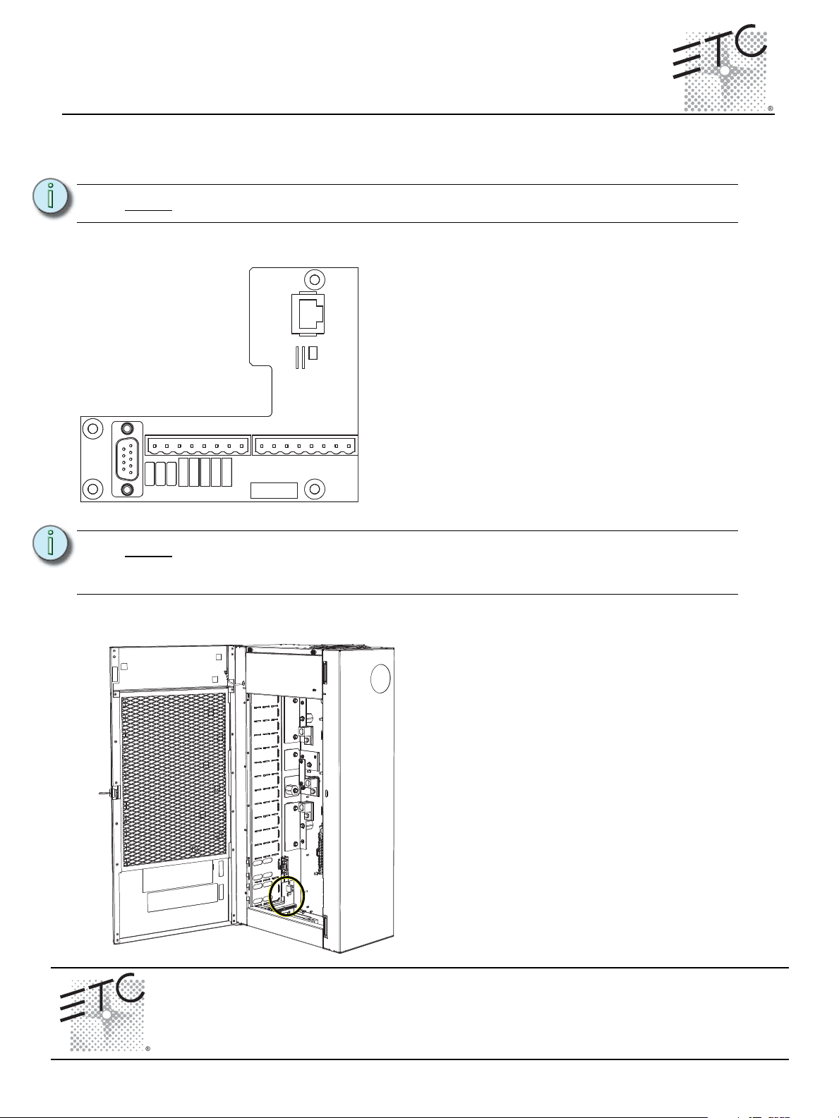
The left I/O board supports the Paradigm architectural
control processor data terminations including:
• RS-232 on a male 9 pin (D style) connector
• Ethernet on a RJ-45 female connector
• Contact closure input terminations on a 8 pin
pluggable connector. Terminations available for 4
inputs and 4 ground wires.
• Contact closure output terminations on a 8 pin
pluggable connector. Terminations available for 4
normally open relay outputs and 4 common wires.
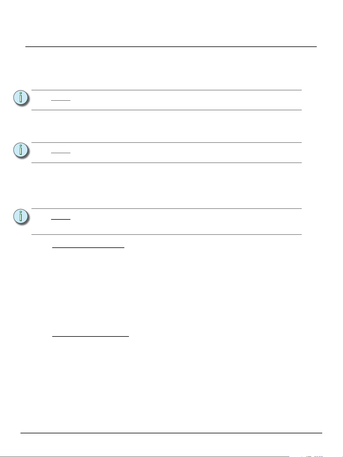
Step 1: Align the left I/O board to the mounting
pems on the left side of the DRd enclosure.
Step 2: Secure with the screws provided.
Paradigm DRd Termination Kit Installation
Overview
The Paradigm DRd termination kit (P-DRd-TK) is provided for field installation into a DRd enclosure for
use with a Paradigm architectural control processor. This kit includes the DRd left I/O board.
Note:
All low voltage control cables must run in separate conduit from power wires.
The left I/O board should be installed by the installing contractor or qualified field technician.
Note:
Data terminations to the left I/O board are specific to use with the Paradigm
architectural control processor (P-ACP) and are not compatible with an installed
SmartLink architectural control processor (S-ACP).
Installation
Corporate Headquarters
London, UK
Rome, IT
Holzkirchen, DE
Hong Kong Rm 1801, 18/F, Tower 1 Phase 1, Enterprise Square, 9 Sheung Yuet Road, Kowloon Bay, Kowloon, Hong Kong Tel +852 2799 1220 Fax +852 2799 9325
Service:
Paradigm DRd Termination Kit Setup Guide Page 1 of 2 Electronic Theatre Controls, Inc.
Web:
7182M2230
Unit 26-28, Victoria Industrial Estate, Victoria Road, London W3 6UU, UK Tel +44 (0)20 8896 1000 Fax +44 (0)20 8896 2000
Via Ennio Quirino Visconti, 11, 00193 Rome, Italy Tel +39 (06) 32 111 683 Fax+44 (0)20 8896 2000
(Americas) service@etcconnect.com
www.etcconnect.com
Rev A Released 09/2008
3031 Pleasant View Road, P.O. Box 620979, Middleton, Wisconsin 53562-0979 USA Tel +608 831 4116 Fax +608 836 1736
Ohmstrasse 3, 83607 Holzkirchen, Germany Tel +49 (80 24) 47 00-0 Fax +49 (80 24) 47 00-3 00
Copyright © 2008 ETC. All Rights Reserved. Product information and specifications subject to change.
(UK) service@etceurope.com (DE) techserv-hoki@etcetcconnect.com.com
(Asia) service@etcasia.com
Page 2
ETC Setup Guide
Connect to Serial RS-232
Integrators or users of advanced systems can interface with the Unison system through the RS-232
connector on the left I/O board. This connection provides an interface with external devices capable of
sending or receiving RS-232. This connection can also receive serial commands from a transmitter and
provide rack and system status when queried.
Paradigm DRd Termination Kit
Note:
The RS-232 cable (not supplied) should follow common RS-232 pinout for a DB9
receptacle (pin 2 is RS-232 Rx, pin 3 is RS-232 Tx, and pin 5 is ground).
Connect to Ethernet RJ-45
Network interface to the ERn enclosure is made through the RJ-45 connector (labeled Ethernet)
located on the left I/O board.
Note:
All Ethernet terminations must follow IEEE 802.3 and be terminated to the T568B
standard.
Connect to Contact Inputs and Contact Outputs
The left I/O provides a convenient interface (inputs and outputs) to external devices via contact closure
on removable pluggable connectors. Maintained or momentary operation is specified in the Paradigm
configuration using LightDesigner software. Up to four contact outputs are available and are preset for
normally open operation.
Note:
Terminate Contact Inputs
Step 1: Remove the contact inputs removable screw terminal connector located on the left I/O
Step 2: Strip 3/16” (5mm) of insulation from the ends of each wire pair.
Step 3: Loosen the required number of contact input screw terminals and related ground screw
Step 4: Insert contact closure 1 into the terminal labeled “IN1” on the connector and tighten the
Step 5: Insert the related ground wire for contact closure 1 into the terminal labeled “GND” on the
Step 6: Repeat for each contact input and ground wire pair required (up to four total).
Typical contact I/O wiring is color coded as follows: contact 1 - brown, contact 2 orange, contact 3 - yellow, contact 4 - green. All commons and ground voltages
are typically black or red.
board. Each connector is labeled for installation convenience.
terminals on the connector.
screw terminal.
connector and tighten the screw terminal.
Terminate Contact Outputs
Step 1: Remove the contact outputs removable screw terminal connector located on the left I/O
board. Each connector is labeled for installation convenience.
Step 2: Strip 3/16” (5mm) of insulation from the ends of each wire pair.
Step 3: Loosen the required number of contact output (normal open) screw terminals and related
ground screw terminals on the connector.
Step 4: Insert contact output 1 into the terminal labeled “N.O.1” on the connector and tighten the
screw terminal.
Step 5: Insert the related common wire for contact output 1 into the terminal labeled “COM1” on
the connector and tighten the screw terminal.
Step 6: Repeat for each contact output and common wire pair required (up to four total).
Paradigm DRd Termination Kit Setup Guide Page 2 of 2 Electronic Theatre Controls, Inc.
 Loading...