

Page 1
ETC® Installation Guide
Unison® DRd Right I/O Card Upgrade Kit
Overview
The DRd Right I/O Upgrade kit is available to upgrade an existing DRd enclosure to be used with the
Unison Echo Architectural Control Processor.
Note:
Kit includes:
The DRd right I/O card and five 6-32 x .250 screws.
Required tools:
• No. 2 Phillips screwdriver
• Slotted screwdriver (optional)
Procedure
WARNING:
Preparation
Step 1: Turn off power to the DRd enclosure.
The right I/O card in this upgrade kit maintains compatibility for all existing Paradigm
and SmartLink Architectural Control Processors.
Power must be turned OFF when you perform this procedure. Before service,
de-energize main feed to dimmer enclosure and follow appropriate Lockout/
Tagout procedures as described in NFPA Standard 70E.
It is important to note that electrical equipment such as dimmer enclosures can
present an arc flash safety hazard if improperly serviced. This is due to available
large short circuit currents on the feeders of the equipment. Any work on
energized equipment must comply with OSHA Electrical Safe Working
Practices.
WARNING:
Failure to disconnect all power to the DRd before working in the enclosure
could result in serious injury or death.
Step 2: Loosen screws on the module retention rail on the left side of the DRd enclosure and slide
the rail to the left.
Step 3: If installed, remove the Architectural Control Processor, Station Power Module, and at
least three dimmer modules from the lower portion of the dimmer enclosure to provide
work space inside the enclosure.
Step 4: Use a digital voltmeter and verify that power is off by checking voltages for all
combinations between the phase bars, neutral, and ground (earth).
Corporate Headquarters
London, UK
Rome, IT
Holzkirchen, DE
Hong Kong Rm 1801, 18/F, Tower 1 Phase 1, Enterprise Square, 9 Sheung Yuet Road, Kowloon Bay, Kowloon, Hong Kong Tel +852 2799 1220 Fax +852 2799 9325
Service:
Web:
7186M2120
Unit 26-28, Victoria Industrial Estate, Victoria Road, London W3 6UU, UK Tel +44 (0)20 8896 1000 Fax +44 (0)20 8896 2000
Via Pieve Torina, 48, 00156 Rome, Italy Tel +39 (06) 32 111 683 Fax +44 (0) 20 8752 8486
(Americas) service@etcconnect.com
www.etcconnect.com
Rev A Released 2014-05
3031 Pleasant View Road, P.O. Box 620979, Middleton, Wisconsin 53562-0979 USA Tel +608 831 4116 Fax +608 836 1736
Ohmstrasse 3, 83607 Holzkirchen, Germany Tel +49 (80 24) 47 00-0 Fax +49 (80 24) 47 00-3 00
Copyright © 2014 ETC. All Rights Reserved. Product information and specifications subject to change.
(UK) service@etceurope.com (DE) techserv-hoki@etcconnect.com
ETC intends this document to be provided in its entirety.
(Asia) service@etcasia.com
Right I/O Card Upgrade Kit Installation Page 1 of 4 Electronic Theatre Controls, Inc.
Page 2
ETC Installation Guide
b: Gently slide the option card to the left,
disconnecting the card edge connector
from the right I/O card.
c: Move the option card to the left side of
the enclosure, keeping the wiring
connections in place if possible.
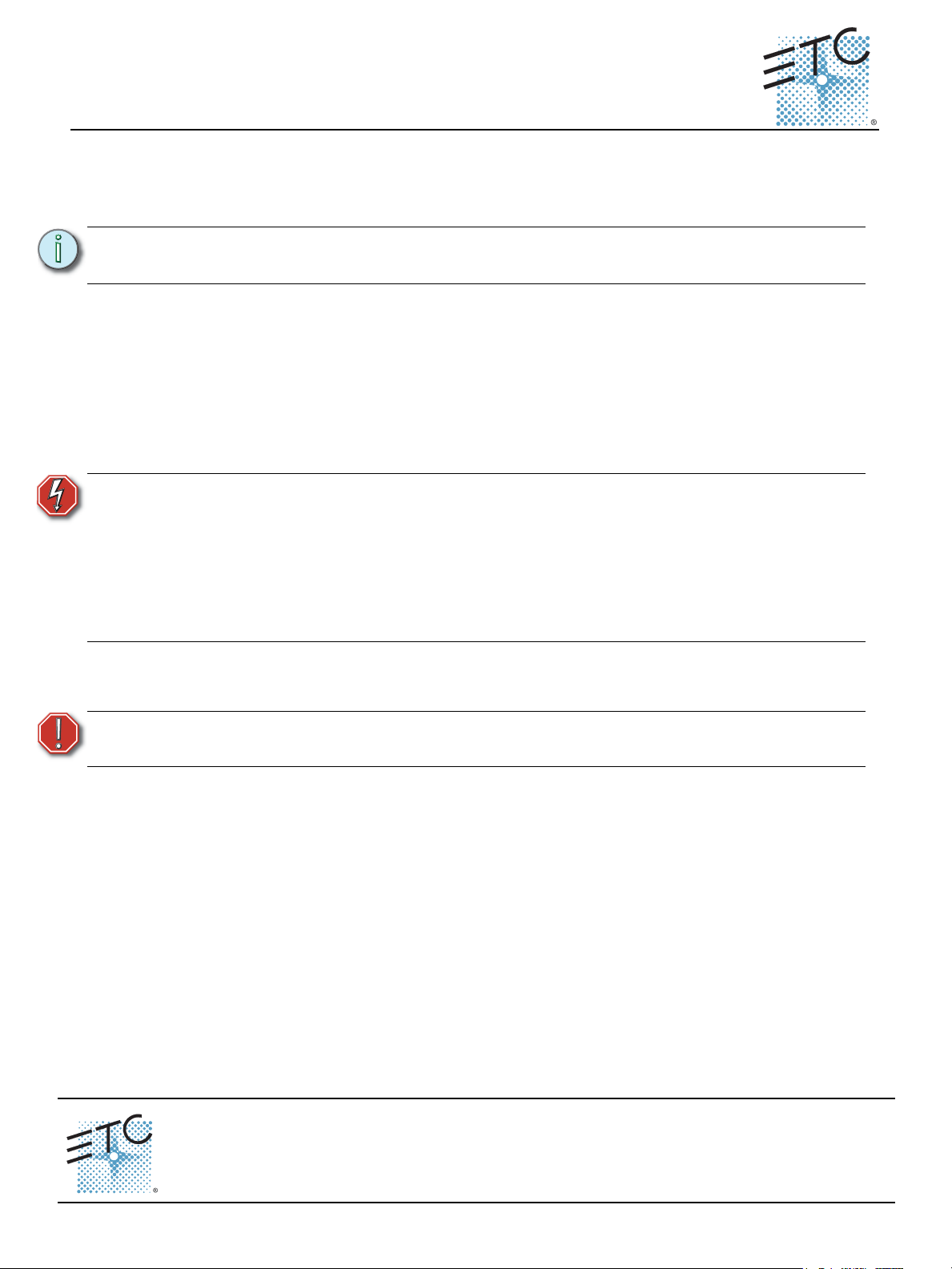
Step 3: Remove the hardware securing the right I/O card in the DRd
enclosure.
Step 4: Gently slide the right I/O card down, disconnecting the top
card edge connector from the signal distribution board.
Remove the existing I/O Card
All connections to the right I/O card are made to removable pluggable connectors, making this upgrade
very simple.
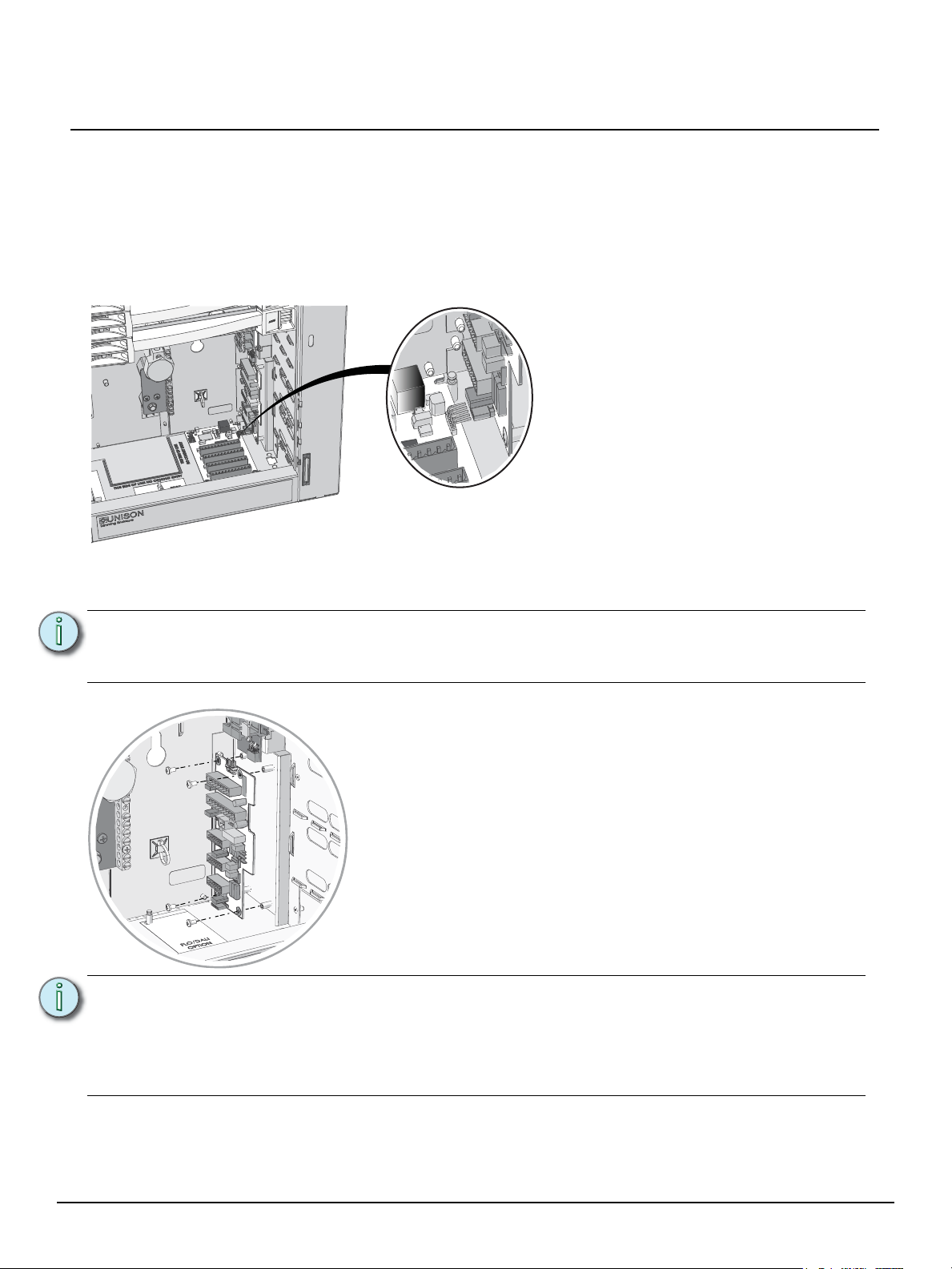
Step 1: If a Fluorescent Option or DALI Option card is installed, temporarily remove the option
card before proceeding with the right I/O removal.
a: Remove the hardware securing the option card in the enclosure. Keep the hardware in a
safe location for reinstallation later.
Right I/O Card Upgrade
Step 2: Disconnect all pluggable connectors from the right I/O card. Be certain to label similar
connectors (including DMX) for easy reinstallation later.
Note:
Note:
The connector plugs can be difficult to disconnect. Do not pull on any of the wires to
remove the connection. If you are having difficulty removing the connectors, carefully
use the edge of a slotted screwdriver to pry the connector free from the receptacle.
Retain this original right I/O card to verify DMX termination settings for the
replacement I/O card.
Once the upgrade is complete, this right I/O card is no longer needed and can be
recycled at a local certified electronics recycler or it can be sent back to ETC for proper
disposal. The circuit board should not be disposed of in the general trash.
Right I/O Card Upgrade Kit Installation Page 2 of 4 Electronic Theatre Controls, Inc.
Page 3

ETC Installation Guide
SIGNAL DISTRO
RIDE THRU/BATT
J9
DUAL RACKS
LPS
APM
DMXB
AUX POWER
LON LINK / ECHO BUS
CDI
DMXA
B+ B- COM A+ A- COM
7183B4606 REV F © 2013 ETC, INC. MADE IN THE U.S.A.
B+ B- COM
COM PANIC
A+ A- COM
DMXB DMXA
SRC OFF END
DMX PASS-THRU
Step 3: Reconnect all pluggable connectors to their appropriate
receptacle on the right I/O card, ensuring they are fully
seated.
The following connections are available, but may not be
used by every installation.
•Aux Power
• LON Link Power/ Echo Bus
• Ride Thru / Battery Backup
• Com / Panic
• Dual Racks (if Auxiliary rack installed)
•DMX A
•DMX Pass-Thru
•DMX B
Install the new I/O Card
Step 1: Gently slide the new right I/O card edge connector into the receptacle on the signal
distribution board. Make certain each pin is aligned to its correct receptacle.
Step 2: Secure the right I/O card in place using four of the screws provided in this upgrade kit.
Right I/O Card Upgrade
Note:
When reconnecting DMX, be sure each connector is replaced to the correct
receptacle. DMX A is the top receptacle, DMX Pass-Thru is the middle receptacle, and
DMX B is the bottom receptacle.
Step 4: Locate the DMX termination switches on the right I/O card. Terminate them to the correct
setting based on your installation. You may refer to the old right I/O card to determine the
previous DMX termination settings.
• Source - reserved for future development
• Off - no termination, DMX will pass by this device to the next DMX device in the data
run
• End - termination is on. Used for the last DMX device (e.g. DRd enclosure) that is
physically connected in the daisy-chained DMX In data run.
Step 5: Reinstall the option card (if used).
a: Align the option card to the mounting studs in the bottom right side of the enclosure.
b: Set the rear left stud through the slotted keyhole and align the open ended slot with the
c: Gently slide the option card toward the right I/O card, aligning the card edge connector to
d: Secure the bottom two mounting studs with the screws previously removed.
Right I/O Card Upgrade Kit Installation Page 3 of 4 Electronic Theatre Controls, Inc.
e: Check each pluggable connector on the option card to ensure it is fully seated.
• Notice the mounting holes on the option card. One is a slotted keyhole, another is
an open ended slot, and the remaining two on the other end of the board are
standard mounting holes used to secure the card in place.
back right side mounting stud.
the receptacle on the right I/O card. Make certain each pin is aligned to its correct
receptacle.
Page 4

ETC Installation Guide
Step 6: Replace the dimmer modules, Station Power Module and Architectural Control Processor
into the slots they were previously removed.
Right I/O Card Upgrade
WARNING:
Step 7: Slide the module retention bar to the right and tighten the screws to secure it in place.
Step 8: Supply power to the DRd enclosure.
Step 9: Unless structural changes are being made to the existing system, no dimming or
Never power up or operate the Unison DRd enclosure without all modules
installed. Failure to comply exposes you to dangerously high voltages that may
result in death by electrical shock.
architectural re-configuration should be necessary. If the system is being modified,
reference the related Architectural Control Processor Configuration and Programming
Guide for configuration setup and operation information.
Right I/O Card Upgrade Kit Installation Page 4 of 4 Electronic Theatre Controls, Inc.
 Loading...