

Page 1
ETC® Setup Guide
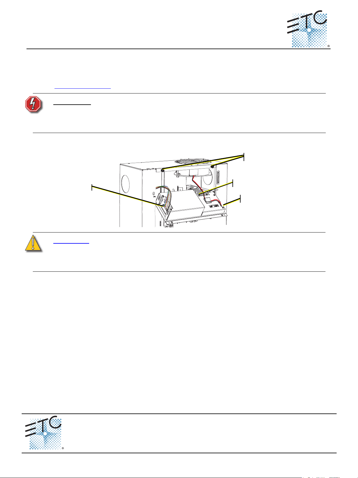
Step 3
Step 6a
Step 6b
Step 6c
The rack door has been
removed from this graphic
for clarity of this procedure.
Unison® DRd Dimming Engine Replacement
Overview
This guide outlines the procedure for removing and replacing the Unison® DRd dimming engine. For
more information on installing the Unison DRd, please refer to the Unison DRd Rack Enclosure
Installation Manual that shipped with your rack or you may download it from our website at
www.etcconnect.com
.
WARNING:
Before removing the Dimming Engine, de-energize main feed to the dimmer rack
and follow appropriate Lockout/Tagout procedures as described in NFPA
Standard 70E. It is important to note that electrical equipment such as dimmer
racks can present an arc flash safety hazard if improperly serviced. This is due
to available large short circuit currents on the feeders of the equipment.
Remove the DRd Dimming Engine
CAUTION:
Before installing the new dimming engine, verify the voltage of the installed unit
matches the voltage of the replacement (labeled on the front panels). If the two are
different, do not install the replacement. Installing an incorrect voltage dimming
engine can result in equipment failure. Contact your authorized dealer or ETC
Technical Services for further assistance.
Step 1: Turn off power to the enclosure and follow appropriate safety procedures.
Step 2: Remove the top dimmer module from the enclosure.
Step 3: Loosen the two captured screws that secure the dimming engine panel.
Step 4: Gently pull the panel straight down until the top of the dimming engine panel is clear of the
Step 5: Tilt the dimming engine away from the rack enclosure.
Step 6: Disconnect the three cables that are attached to the unit:
Step 7: Remove the dimming engine:
enclosure.
a: For the cable bundle on the left side, squeeze the tabs on either side of the connector and
gently pull the cable until it is free from the unit.
b: For the ribbon cable connected on the right rear side, release the tabs on either side of the
connector by sliding them opposite the connector then gently pull the cable free.
c: For the 2-wire harness cable on the right side, gently pull the connector straight out.
a: Align the panel perpendicular to the rack.
b: Slide the panel up approximately one inch to align the guide pins with the top of the guide
slots.
c: Pull the panel straight out.
Corporate Headquarters
London, UK
Rome, IT
Holzkirchen, DE
Hong Kong Rm 1801, 18/F, Tower 1 Phase 1, Enterprise Square, 9 Sheung Yuet Road, Kowloon Bay, Kowloon, Hong Kong Tel +852 2799 1220 Fax +852 2799 9325
Service:
Web:
7183M2280
Unit 26-28, Victoria Industrial Estate, Victoria Road, London W3 6UU, UK Tel +44 (0)20 8896 1000 Fax +44 (0)20 8896 2000
Via Pieve Torina, 48, 00156 Rome, Italy Tel +39 (06) 32 111 683 Fax +44 (0) 20 8752 8486
(Americas) service@etcconnect.com
www.etcconnect.com
Rev B Released 2012-02 ETC intends this document to be provided in its entirety.
3031 Pleasant View Road, P.O. Box 620979, Middleton, Wisconsin 53562-0979 USA Tel +608 831 4116 Fax +608 836 1736
Ohmstrasse 3, 83607 Holzkirchen, Germany Tel +49 (80 24) 47 00-0 Fax +49 (80 24) 47 00-3 00
Copyright © 2012 ETC. All Rights Reserved. Product information and specifications subject to change.
(UK) service@etceurope.com (DE) techserv-hoki@etcconnect.com
(Asia) service@etcasia.com
DRd Dimming Engine Setup Guide Page 1 of 3 Electronic Theatre Controls, Inc.
Page 2
ETC Setup Guide
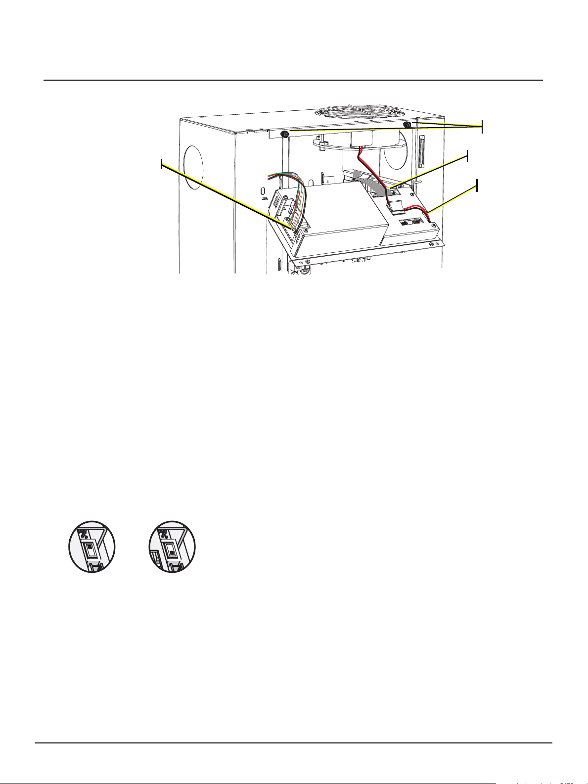
Step 5
Step 2a
Step 2b
Step 2c
The rack door has been
removed from this graphic
for clarity of this procedure.
semi-recessed
DRd installation
standard DRd
installation
• For a semi-recessed DRd installation, set the switch to the position
that is away from the 2-wire harness.
• For a standard DRd installation, set the switch closest to the 2-wire
harness.
Replacing the DRd Dimming Engine
Step 1: Replace the dimming engine.
a: Align the panel perpendicular to the enclosure.
b: Align the guide pins into the top of the guide slots.
c: Slide the panel down the guided slots.
Step 2: Reconnect the three cables to the panel:
a: For the cable bundle on the left side, push the cable into the connector. The black wire will
be closest to you and the blue will be farthest away. The first and sixth pins are flat on one
side to prevent the cable from being connected the wrong way.
b: For the ribbon cable on the right rear side, gently push the cable into the connector. The
tabs on the sides of the connector will close when the cable is properly connected. The
ribbon cable has a small tab to prevent it from being connected the wrong way. The tab will
be toward the rear of the enclosure.
c: For the two-wire cable on the right side, gently push the connector straight down. The black
wire will be toward the right side of the rack, and the red will be toward the left.
d: A fan speed switch is located above the 2-wire harness (fan harness) on the dimming
engine. Ensure that the switch is in the correct position for the installation type.
DRd Dimming Engine Replacement
Step 3: Tilt the dimming engine toward the rack enclosure.
Step 4: Gently push the dimming engine up.
Step 5: Tighten the two captured screws to secure the panel to the rack.
Step 6: Replace the first dimmer module.
Step 7: Reapply power to the enclosure.
DRd Dimming Engine Setup Guide Page 2 of 3 Electronic Theatre Controls, Inc.
Page 3

ETC Setup Guide
DRd Dimming Engine Replacement
Dimming Configuration Mismatch
When power is applied to the rack, the architectural control
processor (ACP) may display a dimming configuration mismatch
error on reboot. The dimming engine and the ACP both store a copy
of the dimming configuration.
For replacement of a dimming engine into a functional DRd rack
containing its original ACP, select “No”, then select “Use backup
config” when it displays. The replacement dimming engine will then load the configuration that is stored
in the ACP.
For other situations, please refer to the Paradigm or Smartlink Architectural Control Processor
Configuration Manual. The appropriate manual shipped with your processor, or you may download it
from our website at www.etcconnect.com
.
Attention:
Dimming Configuration
Mismatch Detected!
Use the Dimming Rack
Configuration?
Yes
No
Help
DRd Dimming Engine Setup Guide Page 3 of 3 Electronic Theatre Controls, Inc.
 Loading...