

Page 1
ETC® Setup Guide
Step 2:
Step 3:
Step 4:
Unison® DALI Option Kit Installation
Note:
It is best to install rack options after conduit rough-in and the line, load and control terminations
are complete to reduce the likelihood of damage to the option board.
DALI Option Kit
Overview
The Digital Addressable Lighting Interface option kit (DRd-DALI) controls 24 loops of 64 DALI
compatible fluorescent ballasts in a broadcast mode. Each of the 24 DALI loops are linked one
to one with a rack circuit for power control. For example, DALI loop 1 is controlled by DRd rack
dimmer 1, DALI loop 2 is controlled by DRd rack dimmer 2, etc.
To control DALI fluorescent ballasts, the rack circuit must be populated with a dimmer or relay
module and assigned to DALI dimmer mode within the ACP software. Reference the related
architectural control processor programming guide for instruction to change dimmer mode.
Note:
The DALI option kit is limited to 64 DALI compatible fluorescent ballasts per DALI loop. All DALI
fluorescent ballasts connected to that loop will respond at the same time and to the same level
as sent by the broadcast command.
A single DRd rack supports the use of either the DALI option kit or the FLO option
kit, but not both in the same rack.
The DALI ballast is powered by an external DALI loop power supply (supplied by
others). This supply is connected externally of the DRd rack. Each DALI loop
requires its own power supply and possibly more than one power supply
depending on the load.
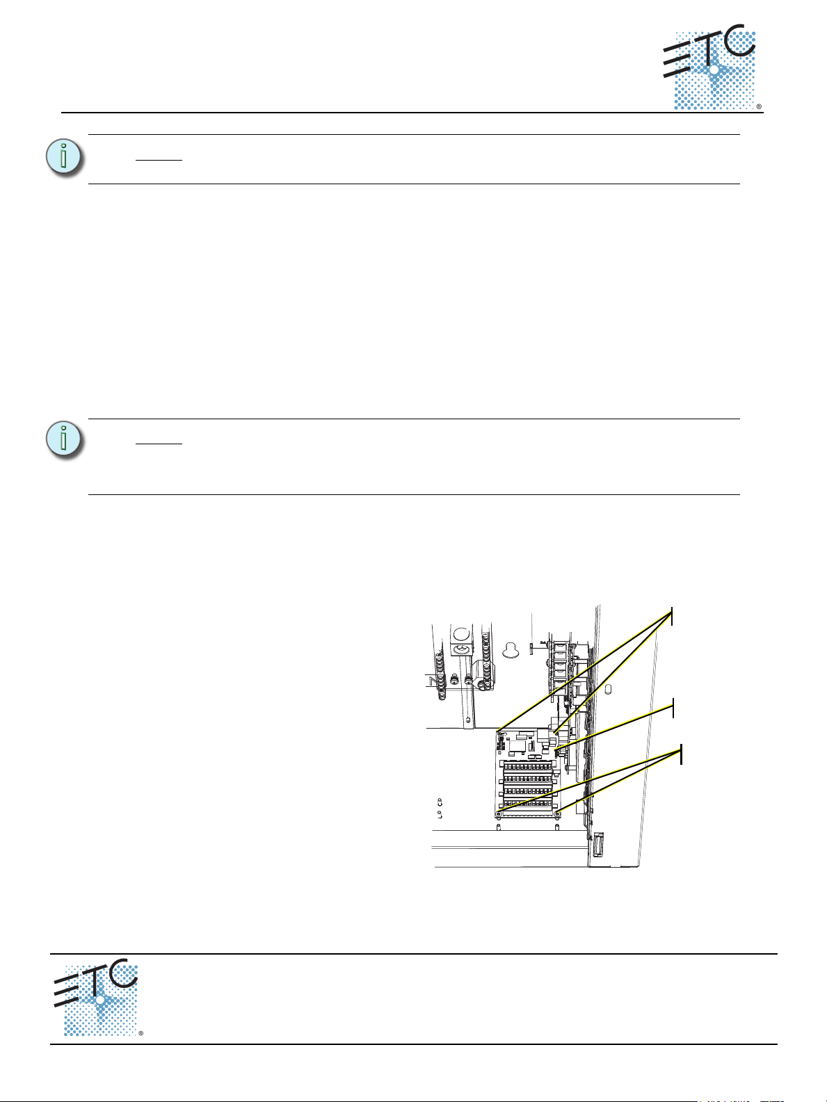
Install the DALI Option Board
Step 1: Align the DALI option board to
the mounting studs in the
bottom right side of the DRd
rack.
• Notice the mounting holes
on the DALI option board.
One is a slotted keyhole,
another is an open ended
slot, and the remaining
two on the other end of
the board are standard
mounting holes used to
secure the board in place.
Step 2: Set the rear left stud through
the slotted keyhole and align
the open ended slot with the
back right side mounting stud.
Step 3: Gently slide the DALI board toward the right I/O board aligning the five prong
connector to the receptacle on the right I/O board.
Step 4: Secure the bottom two mounting studs with the screws provided.
Corporate Headquarters
London, UK
Rome, IT
Holzkirchen, DE
Hong Kong Rm 1801, 18/F, Tower 1 Phase 1, Enterprise Square, 9 Sheung Yuet Road, Kowloon Bay, Kowloon, Hong Kong Tel +852 2799 1220 Fax +852 2799 9325
Service:
Web:
7183M2210
Unit 26-28, Victoria Industrial Estate, Victoria Road, London W3 6UU, UK Tel +44 (0)20 8896 1000 Fax +44 (0)20 8896 2000
Via Pieve Torina, 48, 00156 Rome, Italy Tel +39 (06) 32 111 683 Fax +44 (0) 20 8752 8486
Ohmstrasse 3, 83607 Holzkirchen, Germany Tel +49 (80 24) 47 00-0 Fax +49 (80 24) 47 00-3 00
(Americas) service@etcconnect.com
www.etcconnect.com
Rev C Released 2012-02 ETC intends this document to be provided in its entirety.
3031 Pleasant View Road, P.O. Box 620979, Middleton, Wisconsin 53562-0979 USA Tel +608 831 4116 Fax +608 836 1736
Copyright © 2012 ETC. All Rights Reserved. Product information and specifications subject to change.
(UK) service@etceurope.com (DE) techserv-hoki@etcconnect.com
(Asia) service@etcasia.com
Unison DALI Option Kit Setup Guide Page 1 of 2 Electronic Theatre Controls, Inc.
Page 2
ETC Setup Guide
2008
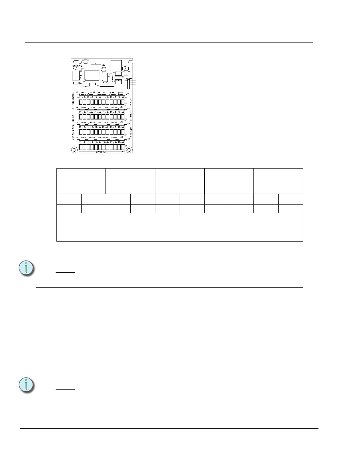
Each of the four bus connectors on the option board provide
termination for six DALI loops. Each bus connector is labeled
for ease of loop identification and is pluggable for ease of wiring
termination. Terminals accept 12-24 AWG (4 - .25mm
2
) Class
1 wire.
Connect DALI Option Wiring
*Maximum Run Lengths for Class 1 wiring
Unison® DALI Option Kit
18 AWG
2
1mm
16 AWG
1.3 mm
14 AWG
2
1.6 mm
2
12 AWG
2
2 mm
**Max.
aggregate run
length
feet meter feet meter feet meter feet meter feet meter
570 175 900 275 1,430 435 2,280 700 3000 900
*Maximum Run Length - the longest distance between any device and any power supply on the
DALI bus.
**Maximum Aggregate Run Length - the longest total length of all total wiring connected to the
DALI bus.
It is important to label the DALI fluorescent ballast load and control wiring sets with the circuit
designation. Control wires terminate on the associated DALI board output loop terminal.
Note:
For example: If circuit 1 is configured as a D20 in DALI dimmer mode, DALI fluorescent ballast
control wiring should terminate to the DALI board loop output terminals labeled “1”.
Step 1: Remove the DALI bus connector for loop outputs 1-6.
Step 2: Strip each wire in the pair back 1/4 inch (6mm).
Step 3: Using a jewelers screwdriver, loosen the terminals and insert each wire into the data
Step 4: Tighten the terminal screw until the wire is held snugly.
Step 5: Repeat steps 1 through 4 for the remaining DALI loops through loop 6.
Step 6: Replace the DALI bus connector on the DALI board and repeat for the remaining
Note:
The associated output loop terminal number should always match the straight
power circuit numbering label inside the rack, regardless of straight or balanced
rack dimmer configuration.
“+” or data “-” terminals for the specific circuit loop. Data wires in the wire set are
polarity independent.
DALI loops in the system (up to 24 loops).
DALI wiring can be run in the same conduit as the power wiring for the same
ballast.
Unison DALI Option Kit Setup Guide Page 2 of 2 Electronic Theatre Controls, Inc.
 Loading...