

Page 1
Auxiliary Enclosure Series
Installation Manual
Revision A
Copyright © 2008 Electronic Theatre Controls, Inc.
All Rights reserved.
Product information and specifications subject to change.
Part Number:
7183M2110
Released: 08/2008
Rev A
Page 2

ETC®, Unison®, EDMX™ are either registered tr ademarks or trademarks of Electronic Theatre Controls, Inc. in
the United States and other countries.
All other trademarks, both marked and not marked, are the property of their respective owners.
ETC permits the reproduction o f materials in this manual only for non-commercial pur pose s. All other rights are
reserved by ETC.
ETC int en ds this documen t, whet her printe d or electronic, to b e provided in i ts entirety.
Page 3

Table of Contents
Introduction . . . . . . . . . . . . . . . . . . . . . . . . . . 1
Warnings and Notice Conventions . . . . . . . . . . . . . . . . . . . . . . . . . . .1
Contacting ETC . . . . . . . . . . . . . . . . . . . . . . . . . . . . . . . . . . . . . . . . .2
Unison Auxiliary Enclosure . . . . . . . . . . . . . . . . . . . . . . . . . . . . . . . .3
Prepare for Installation . . . . . . . . . . . . . . . . .4
Unpack and Inspect . . . . . . . . . . . . . . . . . . . . . . . . . . . . . . . . . . . . . .4
Main Circuit Breaker Protection . . . . . . . . . . . . . . . . . . . . . . . . . . . . .4
Using 90°C Wire. . . . . . . . . . . . . . . . . . . . . . . . . . . . . . . . . . . . . . . . .4
Maximum Current Draw of Enclosures . . . . . . . . . . . . . . . . . . . . . . .5
Short Circuit Current Rating (SCCR) . . . . . . . . . . . . . . . . . . . . . . . . .5
Where to Install the Enclosure . . . . . . . . . . . . . . . . . . . . . . . . . . . . .6
Clearance Requirements . . . . . . . . . . . . . . . . . . . . . . . . . . . . . . .6
Enclosure Dimensions and Weights . . . . . . . . . . . . . . . . . . . . . .6
Installation Environment Requirements . . . . . . . . . . . . . . . . . . . .7
Wire Routing and Specification . . . . . . . . . . . . . . . . . . . . . . . . . .7
Install Enclosures . . . . . . . . . . . . . . . . . . . . .9
Mounting Auxiliary and DRd Enclosures Together. . . . . . . . . . . . . . .9
Rough-in Conduit and Wiring . . . . . . . . . . .11
Rough-in Line Conduit to the Auxiliary Enclosure . . . . . . . . . . . . . .12
Connect Line Power . . . . . . . . . . . . . . . . . .14
Final Installation and Power Up . . . . . . . . . 18
Check Main Power Wiring . . . . . . . . . . . . . . . . . . . . . . . . . . . . . . . .18
Sealing Enclosure Air Leaks . . . . . . . . . . . . . . . . . . . . . . . . . . . . . .18
Table of Contents i
Page 4
Introduction
Welcome to the installation manual for Unison® AX series auxiliary enclosures. This
manual contains the procedures for safe and efficient installation of an AX main breaker or
AX main lug auxiliary enclosure, and the cross-bussed AX12X auxiliary enclosure.
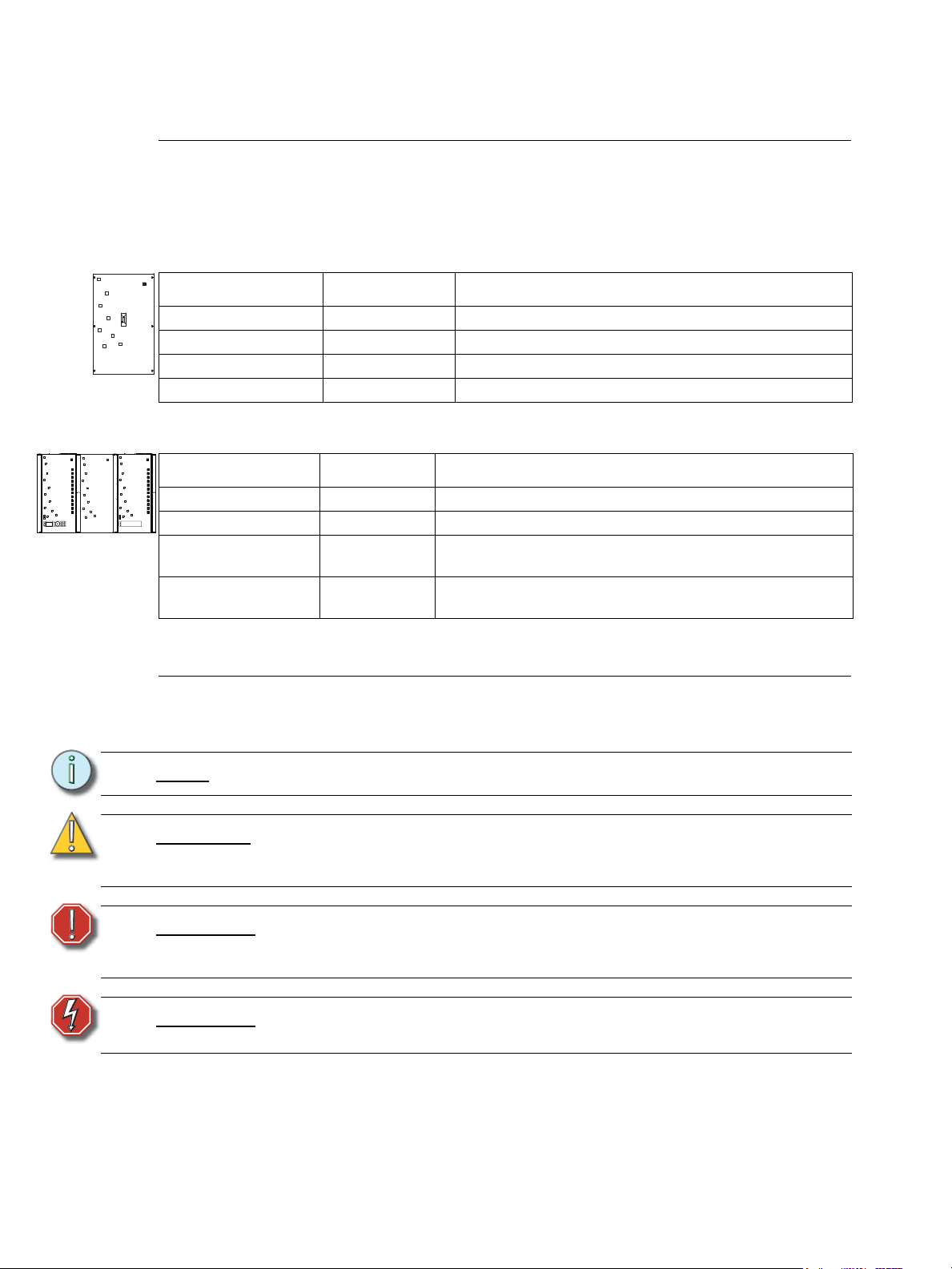
AX Series Auxiliary Enclosures
Series Voltage Notes
AX6-MCB-1-150 100-120 VAC 150A main breaker for DRd6 – 1Ø, 3-wire
AX6-MCB-3-100 100-277 VAC 100A main breaker for DRd6 – 3Ø, 4-wire
AX12-MCB-1-300 100-120 VAC 300A main breaker for DRd12 – 1Ø, 3-wire
AX12-MCB-3-200 100-277 VAC 200A main breaker for DRd12 – 3Ø, 4-wire
AX12X Series Cross-bussed Auxiliary Enclosures
Series Voltage Notes
AX12X-MCB-1-400 100-120 VAC 400A main breaker for (2) DRd12 – 1Ø, 3-wire
AX12X-MCB-3-400 100-277 VAC 400A main breaker for (2) DRd12 – 3Ø, 4-wire
AX12X-ML-1-600 100-120 VAC
AX12X-ML-3-400 100-277 VAC
Main Lug with cross-bussing for (2) DRd12 enclosures – 1Ø,
3-wire
Main lug with cross-bussing for (2) DRd12 enclosures – 3Ø,
4-wire
Warnings and Notice Conventions
These symbols are used in ETC documentation to alert you to danger or important
information:
Note:
CAUTION:
WARNING:
WARNING:
Notes are helpful hints and information that is supplemental to the main text.
A Caution statement indicates situations where there may be undefined or
unwanted consequences of an action, potential for data loss or an equipment
problem.
A Warning statement indicates situations where damage may occur, people
may be harmed, or there are serious or dangerous consequences of an
action.
RISK OF ELECTRIC SHOCK! This warning statement indicates situations
where there is a risk of death by electric shock.
1 Unison Enclosure Installation
Page 5

Contacting ETC
For questions about Unison enclosure system delivery, contact ETC Systems Group. For
general information, your most convenient resources are the references provided in this
manual. To search more widely try the ETC web site at www.etcconnect.com.
For technical questions about Unison enclosure systems, contact ETC Technical Services
directly at one of the offices listed below. Emergency service is available from all ETC
offices outside of normal business hours. When calling for assistance, please have the
following information handy:
• Your location and job name.
• A complete list of ETC equipment.
• A complete list of other installed products and components connected to the system
you are troubleshooting.
• DMX control source, if any.
Americas
ETC International
Technical Services Department
3031 Pleasant View Road
Middleton, WI 53562
800-775-4382 (USA, toll-free)
+1-608 831-4116
service@etcconnect.com
Asia
ETC Asia, Ltd.
Technical Services Department
Room 1801, 18/F, Tower 1, Phase 1
Enterprise Square
9 Sheung Yuet Road
Kowloon Bay, Kowloon, Hong Kong
+852 2799 1220
service@etcasia.com
United Kingdom
Electronic Theatre Controls, Ltd.
Technical Services Department
26 - 28 Victoria Industrial Estate
Victoria Road,
London W3 6UU, UK
+44 (0)20 8896 1000
service@etceurope.com
Germany
Electronic Theatre Controls, GmbH
Technical Services Department
Ohmstrasse 3
93607, Holzkirchen, Germany
+49 (80 24) 47 00-0
techserv-hoki@etcconnect.com
Please email comments about this manual to: TechComm@etcconnect.com
Introduction 2
Page 6
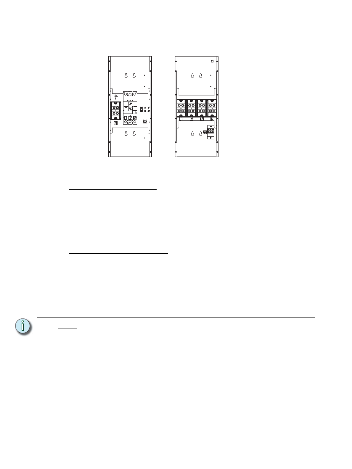
Unison Auxiliary Enclosure
Main LugMain Circuit
Breaker
A main circuit breaker auxiliary enclosure is equipped with breakers that are sized for
maximum load capacity for the DRd configuration.
AX Series Enclosure Options
Unison AX series enclosures are designed to provide main lug or main circuit breaker input
feed provisions for single DRd6 or DRd12 applications.
• AX6-MCB-1-150 – includes main breaker for DRd6, 150A/1Ø, 3-wire
• AX6-MCB-3-100 – includes main breaker for DRd6, 100A/3Ø, 4-wire
• AX12-MCB-1-300 – includes main breaker for DRd12, 300A/1Ø, 3-wire
• AX12-MCB-3-200 – includes main breaker for DRd12, 200A/3Ø, 4-wire
AX12X Series Enclosure Options
Unison AX12X cross-bussing enclosures are designed to provide main lug or main breaker
input feed termination for cross-bussed DRd12 applications.
• AX12X-ML-1-600 – includes cross-bussed main lugs for (2) DRd12, 600A/1Ø, 3-wire
• AX12X-ML-3-400 – includes cross-bussed main lugs for (2) DRd12, 400A/3Ø, 4-wire
• AX12X-MCB-1-400 – includes main breaker for (2) DRd12, 400A/1Ø, 3-wire
• AX12X-MCB-3-400 – includes main breaker for (2) DRd12, 400A/3Ø, 4-wire
Note:
A 600A single phase main circuit breaker is not available due to NEC wire bending
space limitations.
3 Unison Enclosure Installation
Page 7
Chapter 1
Prepare for Installation
Unpack and Inspect
Before you begin installation, check your shipment and confirm it arrived complete and
undamaged.
Step 1: Check the shipping container for physical damage.
Step 2: If you find damage, document it to help with a claim against your shipper.
Step 3: Unpack your order and check the contents against the packing list to be sure
your order is complete.
Step 4: If you discover a problem, call ETC Systems Group at (608) 831-4116.
Main Circuit Breaker Protection
Before you begin installing the Unison auxiliary enclosure, make sure you have installed a
main circuit breaker cabinet or other readily accessible input power disconnect device. In
certain bussed and cross-bussed systems, this disconnect device may be the Unison AX
series auxiliary enclosure with a main circuit breaker.
WARNING:
Note:
Auxiliary enclosures installed without an accessible power disconnect
device cannot be serviced or operated safely. Follow all local codes and
restrictions.
Before removing dimmer or control modules for service, de-energize the main
feed to the dimmer rack and follow appropriate Lockout and Tagout procedures
as described in NFPA Standard 70E. It is important to note that electrical
equipment such as dimmer enclosures can present an arc flash safety hazard if
improperly serviced. This is due to available large Short Circuit Currents on the
feeders of the equipment. Any work on energized equipment must comply with
OSHA Electrical Safe Working Practices.
Using 90°C Wire
The AX MCB cabinets are listed for both copper and aluminum feed wiring, while the ML
cabinets are listed for Copper wire only. Bus cabling to DRd enclosures must use the
included copper cable to satisfy the requirement that the DRd is fed by copper wire only and
to meet UL bend radius limitations. All terminations in the AX and DRd cabinets are listed
for 75°C.
Note:
The terminals may be marked AL9CU indicating a 90°C rating; this is the lug
manufacturer’s rating - not the tested UL listing for the AX enclosure.
1 Prepare for Installation 4
Page 8
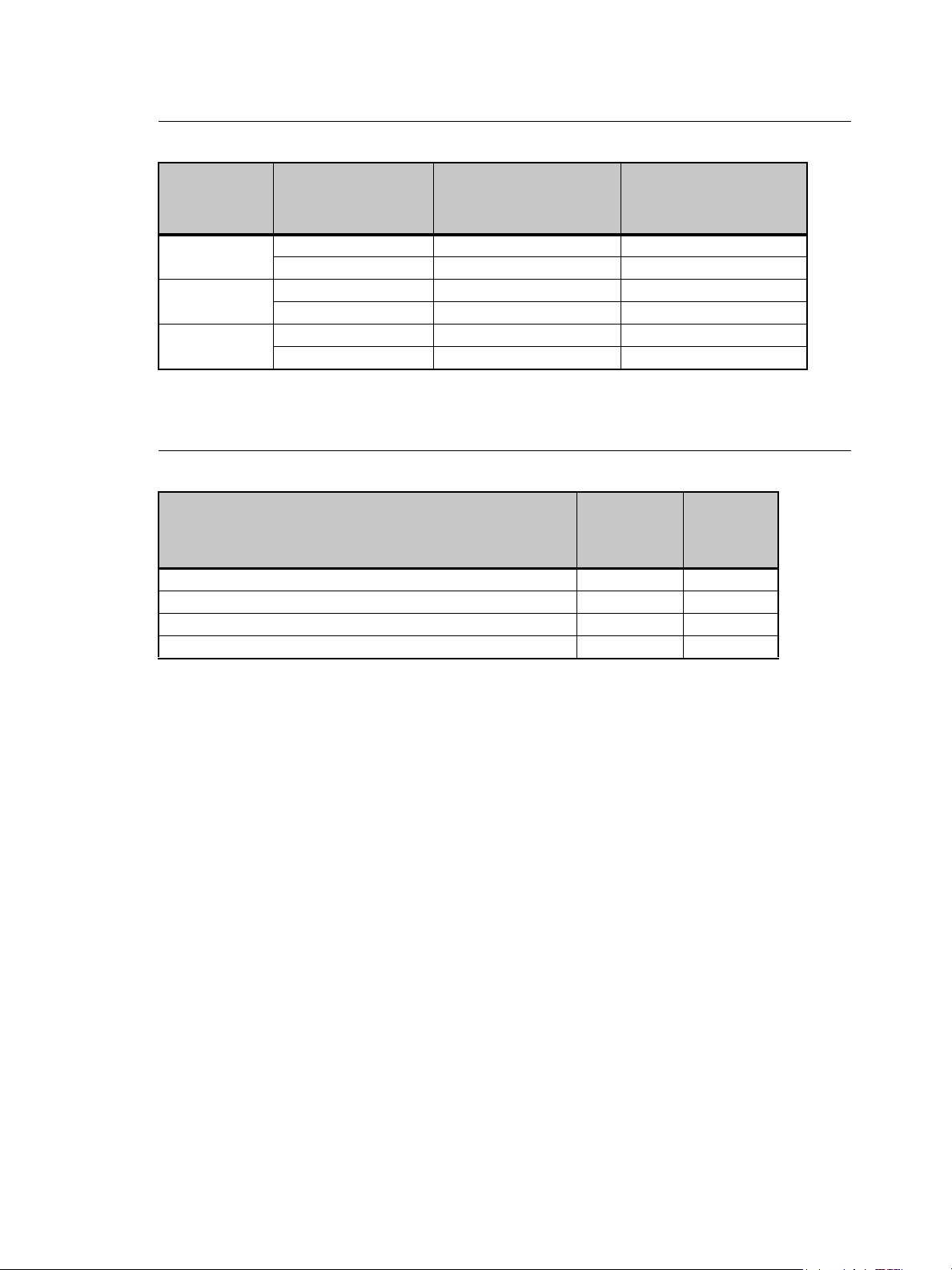
Maximum Current Draw of Enclosures
Enclosure
Type
AX6
AX12
AX12X
a)With 15A modules.
Phase Type
Single phase (1Ø)
Three phase (3Ø)
Single phase (1Ø)
Three phase (3Ø)
Single phase (1Ø)
Three phase (3Ø)
UL Market
Maximum Current
Draw
120A –
80A 60A
240A –
160A 120A
480A –
320A 240A
240V Maximum
Current Draw
Short Circuit Current Rating (SCCR)
SCCR at
Enclosure Configuration
DRd6 with AX6 main circuit breaker enclosure 100,000A 65,000A
DRd12 with AX12X (cross-bussed) main lug enclosure 22,000A 22,000A
DRd12 with AX12 main circuit breaker enclosure 100,000A 65,000A
DRd12 with AX12X main circuit breaker enclosure 100,000A 65,000A
a)Ratings are for three phase systems.
100-120
a
VAC
a
SCCR at
240-277
a
VAC
5 Unison Enclosure Installation
Page 9

Where to Install the Enclosure
Unison DRd enclosures require 12" (305mm) top clearance for proper
airflow through the cabinet. For sufficient door clearance, install the DRd
enclosure with at least 17" (432mm) of front clearance and 6" (152mm)
of clearance to the left of the door hinge from walls or other equipment.
Unison auxiliary enclosures are designed to be surface mounted on load bearing walls in
an electrical closet or a room with restricted public access. It is recommended that you
install the enclosure at least 36" (914.4mm) off the floor surface.
Clearance Requirements
6”
(152 mm)
17”
(432 mm)
12”
(305 mm)
36”
(914.4 mm)
Note:
Additional Unison DRd and auxiliary enclosures of the same size are the
exception to the 6" hinge side clearance rule. Unison enclosures are designed for
side by side use without issue.
Enclosure Dimensions and Weights
Enclosure
Type
AX6 MCB
enclosure
AX12 MCB
enclosure
AX12X ML
enclosure
AX12X MCB
enclosure
a)Note: All weights are approximate.
Height Width Depth
inches mm inches mm inches mm lbs kgs lbs kgs
21.8 553.7 13 330 8 203 27.6 12.5 35 16
31 787 13 330 8 203 33 15 40 20
31 787 13 330 8 203 28 12.7 35 16
31 787 13 330 8 20 33 15 40 20
Product
Weight
a
Shipping
Weight
a
1 Prepare for Installation 6
Page 10

Installation Environment Requirements
• For your safety, you should install a main circuit breaker cabinet or other readily
accessible input power disconnect device in the same area as the Unison auxiliary
enclosure. For bussed enclosure installations, this device may be the auxiliary
enclosure. Main breakers not in the same room must have a physical means to be
locked off.
Note:
Before removing dimmer or control modules for service, de-energize the main
feed to the dimmer rack and follow appropriate Lockout and Tagout procedures
as described in NFPA Standard 70E. It is important to note that electrical
equipment such as dimmer enclosures can present an arc flash safety hazard if
improperly serviced. This is due to available large Short Circuit Currents on the
feeders of the equipment. Any work on energized equipment must comply with
OSHA Electrical Safe Working Practices.
• A clean (not dusty) temperature-controlled environment with an ambient temperature
of 32 to 104°F (0 to 40°C) and ambient humidity of 10 to 90%, non-condensing.
CAUTION:
HVAC systems must at all times maintain the specified ambient temperature at the
enclosure. Unison systems operating within 10°F (5°C) of the upper or lower
temperature limits must strictly follow installation and operation guidelines to
operate reliably.
• Restricted public access to prevent tampering.
• Soundproofing or performance area separation to muffle ventilation fan noise.
Wire Routing and Specification
Unison AX series enclosures have conduit knockouts on both sides of the cabinet for feed
through to the adjacent DRd enclosure(s). The top and bottom are intentionally left blank to
allow holes to be punched to match the incoming conduit.
40°
100°
90°
30°
80°
70°
20°
60°
10°
50°
40°
0°
30°
20°
-10°
10°
0°
-18°
CAUTION:
Do not route line (input feed) wires through the back panel. Doing so requires bend
radii that place undue stress on the input lugs, may damage insulation, and will
violate the UL listing of this enclosure.
CAUTION:
Line (feed) lugs for the Unison AX main circuit breaker enclosures are UL/cUL
listed for use with both copper and aluminum wire, while the main lug enclosures
are listed for copper wire only. Load side terminations used to feed the DRd
enclosures must be the included extra flexible copper wire.
7 Unison Enclosure Installation
Page 11

AX and AX12X Auxiliary Enclosure
It is required that line feed enters from the top or bottom panels of the enclosure. The side
knockouts are provided for cross-bussing and data interconnect feed through to the
adjacent DRd dimming enclosure(s). The corresponding number of chase nipples with
integral bushings are included.
Wire Access
Location
Top of enclosure
Bottom of
enclosure
Left side
Right side
Wire
Feed wire Interconnect wiring to
DRd enclosure
Acceptable Not recommended
Preferred Not recommended
Not recommended Preferred
Not recommended Preferred
1 Prepare for Installation 8
Page 12

Chapter 2
AX6 / DR6 - 16.3”
AX12 / DR12 - 19.9”
16” 11”
AX6 / DR6 - 5.7”
AX12 / DR12 - 7.7”
22”
AX6 / DR6 - 21.9”
AX12 / DR12 - 31”
10.7”
6.3”
AX6 / DR6 - 10.6”
AX12 / DR12 - 7.7”
17” 17”13”
DRd DRdAX
Install Enclosures
Mounting Auxiliary and DRd Enclosures Together
One DRd may be bussed to the AX series auxiliary enclosure, which contains a main circuit
breaker (MCB) for power distribution to the adjacent DRd enclosure.
Two DRd12 enclosures may be cross-bussed to an AX12X which is designed to provide
main lug or main breaker input feed termination to the adjacent DRd12 enclosures.
The wall must be strong enough to hold all enclosures fully populated with modules, conduit
and wire. Reference “Where to Install the Enclosure,” page 6 for weight, dimension and
clearance requirements.
Note:
The AX series enclosure is best installed to the left of the DRd in main lug and
main breaker applications and must be installed between two DRd12 enclosures
in a cross-bussed application.
Step 1: Determine where your enclosures will be installed using the weight and
dimension requirements detailed in “Where to Install the Enclosure,” page 6.
Step 2: Use the measured slot dimensions located in the graphic below to mark the hole
locations for the mounting hardware.
Step 3: Drill the holes and install the mounting hardware for each enclosure.
• Four 3/8” (8mm) bolts or screws 2 to 4" (50-100mm) long, and suitable wall
9 Unison Enclosure Installation
plugs are suggested mounting hardware (lag bolts recommended).
• Both the surface and the mounting hardware must support the weight of
the enclosure unit fully populated with modules.
• Expose at least 1" (25mm) of threads for mounting.
Page 13

Step 4: Remove the knockouts from the side conduit plug on the DRd and auxiliary
enclosure before installation. Only remove the knockouts that are adjacent to
another enclosure.
Step 5: Install the DRd first, following the instructions as outlined in the DRd Enclosure
Installation Manual.
Step 6: Align the auxiliary enclosure against the left side of the DRd enclosure and mount
it to the previously installed mounting hardware. Notice, with conduit holes mated
the bolt spacings are on 16" centers (top left DRd and top left AX enclosure) for
installation convenience.
Step 7: For cross-bussed DRd12 enclosure installations, install the second DRd12 by
following steps 4 through 6 above.
Step 8: Check that each enclosure is level and plumb then tighten the mounting
hardware for a secure installation.
2 Install Enclosures 10
Page 14

Chapter 3
DRd enclosure with AX enclosure
Two DRd12 enclosures with AX12X enclosure
Rough-in Conduit and Wiring
See “Wire Routing and Specification” on page 7. Line or (input feed) wires for standard AX
series enclosures should enter through the top or bottom.
All terminations are accessible from the front of the enclosure.
11 Unison Enclosure Installation
Page 15

Rough-in Line Conduit to the Auxiliary Enclosure
Line input may enter the auxiliary enclosure from
the top or bottom.
The ETC supplied line feed interconnect cables
will feed through the side conduit knockouts to the
adjacent DRd. Reference “Route and Connect
Interconnect Cables to Adjacent DRd
Enclosure(s)”, page 17 for interconnect cable
termination instructions.
Line input wires in main lug, main breaker, or cross-bussed DRd enclosure applications
terminate first in the Auxiliary enclosure and then are fed through the side conduit
knockouts to the adjoining DRd enclosure(s).
The line feed-through (interconnect) cables for phase, neutral and ground lugs in the
auxiliary enclosure are connected for you at the factory. Your enclosure is supplied with one
or two sets of interconnect cables depending on the model ordered.
Step 1: Plan wire entry in to the enclosure. See “Wire Routing and Specification” on
Step 2: Remove the side conduit knockout from adjoining side of the auxiliary enclosure
Step 3: Install the ETC supplied nylon insulated chase nipple to the knockouts between
Step 4: Remove the auxiliary enclosure front cover, and if necessary, the top or bottom
Step 5: Punch conduit holes, top or bottom, as required by the wire entry plan.
Step 6: Install conduit fittings or insert fish paper lining material into the opening.
Step 7: Be sure there are minimal air gaps. See “Sealing Enclosure Air Leaks” on
CAUTION:
page 7.
and the DRd enclosure. When installing in a cross-bussed application, remove
both side knockouts.
the auxiliary and DRd enclosure(s).
front trim covers for complete access to the lugs.
page 18.
Wire openings must have fittings, grommets or fish paper lining material to protect
wire and cable insulation from damage by sharp metal edges and to prevent air
leaks.
When using the 400A breaker frame you must replace the plastic lug covers for
compliance and safe operation.
3 Rough-in Conduit and Wiring 12
Page 16

Main Lug Support Panel Breaker Position
The unit ships with the support panel in the top feed position (shifted to the bottom of the
AX). These positions are to comply with UL and NEC wire bending space requirements.
Step 1: If you are bottom feeding the AX, loosen the 4 nuts from the sides of the
enclosure.
Step 2: Reposition the support panel with the breaker on the main lugs to the top
position.
Step 3: Tighten the nuts.
13 Unison Enclosure Installation
Page 17

Chapter 4
Connect Line Power
WARNING:
CAUTION:
Note:
Line input wires in main breaker or cross-bussed DRd applications terminate in the Auxiliary
enclosure. Interconnect cables are fed through the side conduit knockouts of the auxiliary
enclosure and connect to the adjacent DRd enclosure(s).
Main Breaker power input options include:
• AX6-MCB-1-150 – 1Ø, 3-wire, 150A
All enclosure terminations must be done with the power off. Enclosures
installed without an accessible power disconnect device cannot be serviced
or operated safely. In some instances, this device may be an auxiliary
enclosure with a main circuit breaker. Follow all local codes and
restrictions.
Load wires used with ETC dimming systems must be copper. Do not use wire
containing aluminum. Line wires must be copper for the AX Main Lug enclosures.
Main circuit breaker enclosures are listed for use with copper or aluminum wire.
Before removing dimmer or control modules for service, de-energize the main
feed to the dimmer rack and follow appropriate Lockout and Tagout procedures
as described in NFPA Standard 70E. It is important to note that electrical
equipment such as dimmer enclosures can present an arc flash safety hazard if
improperly serviced. This is due to available large Short Circuit Currents on the
feeders of the equipment. Any work on energized equipment must comply with
OSHA Electrical Safe Working Practices.
• AX6-MCB-3-100 – 3Ø, 4-wire, 100A
• AX12-MCB-1-300– 1Ø, 3-wire, 300A
• AX12-MCB-3-200 – 3Ø, 4-wire, 200A
• AX12X-MCB-1-400 - 1Ø, 4 wire, 400A (use with 2 DRd12 cross-bussed enclosures)
• AX12X-MCB-3-400 – 3Ø, 4-wire, 400A (use with 2 DRd12 cross-bussed enclosures)
Main Lug power input options include:
• AX12X-ML-1-600 – 1Ø, 3-wire, 600A Main lugs (use with 2 DRd12 cross-bussed
enclosures)
• AX12X-ML-3-400 – 3Ø, 4-wire, 400A Main lugs (use with 2 DRd12 cross-bussed
enclosures)
4 Connect Line Power 14
Page 18

Step 1: Pull the line phase, neutral, and ground cables to the enclosure through the
Phase lugs
Neutral lugs
Ground lugs
Neutral lugs
Phase lugs
Ground lugs
Main Lug
Main Circuit Breaker
conduit openings previously prepared.
Step 2: Strip one inch of insulation from the end of each cable and terminate them to the
lugs. Line connections are labeled L1, L2, L3 (for three phase) and N. The
equipment grounding lug is labeled with the universal grounding symbol for easy
identification.
Step 3: Tighten the lugs to the correct torque based on cable size. Refer to the following
table.
15 Unison Enclosure Installation
Page 19

AX
Enclosure
Wire
Lug Wire Range
(Qty.)
Wire Size for
Torque (Qty.)
Lug Wire
Torque
Wrench
Size
3-phase
AX-MCB
1-phase
AX-MCB
AX12X ML
8 AWG to 350 kcmil
Phase
(1)
(10 to 185mm
2
)
4 AWG to 500 kcmil
Neutral
(2)
(25 to 240mm
2
)
Ground 6 to 2/0 AWG
2/0 AWG to 400 kcmil
(2)
2
)
Phase
(70 - 185 mm
or
1 AWG to 600 kcmil
(1)
(50 to 300 mm
2
)
4 AWG to 500 kcmil
Neutral
(2)
(25 to 240mm
2
)
Ground 350 kcmil to 1 AWG
4 AWG to 500 kcmil
Phase
(2)
(25 to 240mm
2
)
4 AWG to 500 kcmil
Neutral
(2)
(25 to 240mm
2
)
Ground 6 to 2/0 AWG
3 to 1 AWG (1)
(25 to 35mm
2
)
1/0 AWG to 350
(50 to 185mm
2
)
4 AWG to 500 kcmil
(2)
(25 to 240mm2)
2/0 to 3 AWG (1)
4 to 6 AWG (1)
2/0 AWG to 400 kcmil
(2)
(70 - 185 mm
2
)
or
1 AWG to 600 kcmil
(1)
(50 to 300 mm
2
)
4 AWG to 500 kcmil
(2)
(25 to 240mm2)
6 to 2 AWG (1)
1 AWG to 350 kcmil
(1)
4 AWG to 500 kcmil
(2)
(25 to 240mm2)
4 AWG to 500 kcmil
(2)
(25 to 240mm2)
2/0 to 3 AWG (1)
4 to 6 AWG (1)
150 in-lb
(17 Nm)
275 in-lb
(31 Nm)
375 in-lb
(42.3 Nm)
50 in-lb
(5.65 Nm)
45 in-lb
(5.1 Nm)
375 in-lb
(42.3 Nm)
375 in-lb
(42.3 Nm)
375 in-lb
(42.3 Nm)
375 in-lb
(42.3 Nm)
375 in-lb
(42.3 Nm)
200 in-lb
(22.6 Nm)
375 in-lb
(42.4 Nm)
5/16”
3/8”
3/16”
5/16”
3/8”
3/8”
3/8”
3/8”
3/16”
4 Connect Line Power 16
Page 20

Route and Connect Interconnect Cables to Adjacent DRd Enclosure(s)
ETC has supplied extra flexible wire for phase, neutral, and ground lugs from the auxiliary
enclosure to the DRd enclosure(s). Once your auxiliary and DRd enclosures are installed,
feed the load wires through the side chase nipples to the adjacent DRd enclosure phase,
neutral, and ground lugs. Your AX6, AX12, or AX12X will be supplied with one or two sets
of cables, depending on the model ordered.
Step 1: Route the ETC supplied interconnect cabling through the conduit knockouts on
either side of the auxiliary enclosure to the adjacent DRd enclosure(s).
.
Note:
Tie wrap the interconnect cables to the back wall of the DRd immediately after
they are pulled through the conduit fitting. This prevents the cables from
unnecessarily restricting the air flow to the fan.
Step 2: Pull each cable to the appropriate lug. It is necessary to cut the cable to the
pre-marked length in DRd6 applications
Step 3: Attach each cable to its appropriate phase, neutral and ground lugs inside the
DRd enclosure using the supplied copper foil to avoid damaging the fine
stranding of the extra flex wire.
Note:
Step 4: Tighten the lugs to the correct torque based on cable size. Refer to the table on
CAUTION:
Step 5: Fill empty spaces of the conduit openings with UL/CE approved filler.
CAUTION:
17 Unison Enclosure Installation
When a single phase auxiliary enclosure is ordered from the factory, the
interconnect cables will be installed in a single-phase configuration. Reference the
DRd Enclosure Installation Manual for instructions to configuring the DRd
enclosure bus for single phase operation.
the previous page.
Failure to use the proper torque when tightening the set screws can cause
premature failure of the equipment.
Air leaks can cause DRd enclosures to shut down due to insufficient air flow.
Reference “Sealing Enclosure Air Leaks,” page 18.
Page 21

Chapter 5
Final Installation and Power Up
It’s a good idea to look over the entire installation before applying power to the system.
WARNING:
Note:
Step 1: Clean out dust and debris from the interior.
Step 2: Check for loose connections, bare wires and damaged insulation.
Step 3: Check for and stop air leaks left in conduit openings, empty screw holes or
Power must be turned OFF when you perform this procedure.
Before removing dimmer or control modules for service, de-energize the main
feed to the dimmer rack and follow appropriate Lockout and Tagout procedures
as described in NFPA Standard 70E. It is important to note that electrical
equipment such as dimmer enclosures can present an arc flash safety hazard if
improperly serviced. This is due to available large Short Circuit Currents on the
feeders of the equipment. Any work on energized equipment must comply with
OSHA Electrical Safe Working Practices.
misaligned panels. For complete instructions for this procedure reference
Sealing Enclosure Air Leaks below.
Check Main Power Wiring
With all modules removed and the power harness to all dimming engines unplugged, check
resistance between phases, neutral and ground busses with a digital voltmeter (DVM).
• Phase to phase resistance should be 10M Ohm or higher.
• Phase to ground resistance should be 10M Ohm or higher.
• Neutral to ground resistance should be 0 Ohm.
• Phase to neutral resistance should be 10M Ohm or higher.
Sealing Enclosure Air Leaks
After you have attached all the conduit to the enclosure(s) and connected all wiring, you
must seal any air leaks created during the installation process. Use UL/cUL approved filler.
Step 1: Seal all conduit access holes.
Step 2: Completely cover all conduit openings with fish paper and UL/cUL approved
filler.
Step 3: Seal any air gaps caused by bent access panels.
Step 4: Fill in any gaps inside partially filled wiring conduit.
Step 5: Fill in other gaps or holes in the cabinet created during installation.
5 Final Installation and Power Up 18
Page 22

Step 6: Any enclosures that are installed side-by-side (bolted together) should only have
minimal airflow between them.
CAUTION:
Air leaks can cause DRd enclosures to overheat during operation and shut down.
Air leaks can also cause a shut down to do an “Airflow Error”, meaning that too
little air is flowing through the front of the enclosure where it is needed to cool the
dimmers.
19 Unison Enclosure Installation
Page 23

5 Final Installation and Power Up 20
Page 24

Corporate Headquarters
London, UK
Rome, IT
Unit 26-28, Victoria Industrial Estate, Victoria Road, London W3 6UU, UK Tel +44 (0)20 8896 1000 Fax +44 (0)20 8896 2000
Via Ennio Quirino Visconti, 11, 00193 Rome, Italy Tel +39 (06) 32 111 683 Fax +44 (0)20 8896 2000
Holzkirchen, DE
3031 Pleasant View Road, P.O. Box 620979, Middleton, Wisconsin 53562-0979 USA Tel +608 831 4116 Fax +608 836 1736
Ohmstrasse 3, 83607 Holzkirchen, Germany Tel +49 (80 24) 47 00-0 Fax +49 (80 24) 47 00-3 00
Hong Kong Rm 1801, 18/F, Tower 1 Phase 1, Enterprise Square, 9 Sheung Yuet Road, Kowloon Bay, Kowloon, Hong Kong Tel +852 2799 1220 Fax +852 2799 9325
Service:
(Americas) service@etcconnect.com
Web:
www.etcconnect.com
7183M2110
Rev A Released 08/2008
Copyright © 2008 ETC. All Rights Reserved. Product information and specifications subject to change.
(UK) service@etceurope.com (DE) techserv-hoki@etcconnect.com
(Asia) service@etcasia.com
 Loading...