

Page 1
Station user manual
Architectural
lighting
control system
Page 2

2 Electronic Theatre Controls, Inc.
Page 3

Limited Warranty
Electronic Theatre Controls, Inc. (ETC)
warrants to the original owner or retail
customer that for a period of two years from
date of delivery of a portable system or
energization of a permanently installed
system its products will be free from
defects in materials and workmanship under
normal use and service. Warranty is limited
to 90 days for rental equipment.
Warranty does not cover any product or part
of a product subject to accident, negligence,
alteration, abuse or misuse, or any
accessories or parts not supplied by ETC.
Warranty does not cover “consumable”
parts such as fuses, lamps, color media or
components warranted directly to the
owner by the original manufacturer. ETC’s
warranty does not extend to items not
manufactured by us. Freight terms on
warranty repairs are FOB ETC factory or
designated repair facility. Collect shipments
or freight allowances will not be accepted.
ETC’s sole responsibility under this warranty
shall be to repair or replace at ETC’s option
such parts as shall be determined to be
defective on ETC’s inspection. ETC will not
assume any responsibility for any labor
expended or materials used to repair any
equipment without ETC’s prior written
authorization. ETC shall not be responsible
for any incidental, general or consequential
damages, damages to property, damages
for loss of use, time, profits or income, or
any other damages.
The owner's obligations during the warranty
period under this warranty are to notify ETC
at ETC's address within one week of any
suspected defect, and to return the goods
prepaid to ETC at their factory or authorized
service center.
THIS WARRANTY IS CONTINGENT ON THE
CUSTOMER’S FULL AND TIMELY
COMPLIANCE WITH THE TERMS OF
PAYMENT SET FORTH IN THE “TERMS
AND CONDITIONS.” THIS WARRANTY IS
EXPRESSLY IN LIEU OF ANY AND ALL
OTHER WARRANTIES EXPRESSED OR
IMPLIED, INCLUDING THE WARRANTIES
OF MERCHANTABILITY AND FITNESS FOR
A PARTICULAR PURPOSE AND OF OTHER
OBLIGATIONS AND LIABILITIES ON OUR
PART. THE OWNER ACKNOWLEDGES
THAT NO OTHER REPRESENTATIONS
WERE MADE TO HIM OR RELIED UPON
HIM WITH RESPECT TO THE QUALITY
AND FUNCTION OF THE GOODS SOLD.
This written warranty is intended as a
complete and exclusive statement of the
terms thereof. Prior dealings or trade usage
shall not be relevant to modify, explain or
vary this warranty. Acceptance of, or
acquiescing in, a course of performance
under this warranty shall not modify the
meaning of this agreement even though
either party has knowledge of the
performance and a chance to object.
Unison Station User Manual 3
Page 4

Contents...
Chapter 1
Introduction
Unison overview............................................................................. 8
........................................................................................ 7
Chapter 2
Basic operation
Control station overview................................................................. 9
Fader station operation ................................................................ 11
To adjust intensities using faders ......................................... 12
To record a Preset .................................................................. 12
To take a “snapshot” from a DMX512 device........................ 12
To select a Preset .................................................................. 13
To temporarily adjust Preset zone levels ..............................13
To temporarily adjust (master) all Preset levels .................... 13
Preset Recall station operation .................................................... 15
To select a Preset .................................................................. 15
To master (raise or lower) a Preset ....................................... 15
LCD station operation ................................................................... 16
To find and select a desired control page ............................. 17
LCD station Preset page ............................................................... 18
To select a preset .................................................................. 18
To record a preset .................................................................. 18
To master (raise and lower) a Preset ....................................18
To take a “snapshot” from a DMX512 device........................ 19
LCD station Zones page ...............................................................20
To select the Zones page ......................................................20
To gradually adjust zone lighting intensities ........................20
To quickly adjust zone lighting intensities ............................ 20
Controlling partitioned spaces ..................................................... 21
To change a wall between open and closed ......................... 21
Wireless Transmitter operation ................................................... 22
To select a Preset .................................................................. 22
To master (raise or lower) a Preset ....................................... 22
Portable Control Connector station .............................................. 23
PC Connector station .................................................................... 23
DMX512 Connector station .......................................................... 23
Link Power Supply......................................................................... 23
................................................................................. 6
4 Electronic Theatre Controls, Inc.
Page 5

Chapter 3
System maintenance
Cleaning dimmer dust filters ........................................................ 24
Vacuuming out dimmer racks ....................................................... 25
Cleaning control station faceplates ............................................. 26
All control faceplates (except the LCD control) ..................... 26
LCD control faceplate (including touchscreen) ...................... 26
Replacing batteries in the Wireless Transmitter ......................... 27
...................................................................... 24
Chapter 4
Contacting Technical Service
ETC Technical Service Phone number........................................... 28
Problem Report form .....................................................................28
Problem Report Form instructions................................................ 29
....................................................... 28
Glossary
............................................................................................ 33
Unison Station User Manual 5
Page 6

6 Electronic Theatre Controls, Inc.
Page 7

Chapter 1
introduction
This manual is designed to assist you in basic operation of the Unison lighting
control system.
This manual covers three areas of Unison operation and maintenance:
▼
Basic operation
▼
System maintenance
▼
Contacting ETC Technical Service
Throughout the manual, button labels appear in brackets (i.e., [Enter]), italics
identify parts of the manual (i.e.,
indicates words that appear on a display (i.e., Record ). If any of the terms you
encounter are unfamiliar, please refer to the
Chapter 2, Basic operation
Glossary
on page 33.
), and bold type
Because each Unison system can be customized for special functions, some
of the illustrations and examples in the
match your system. However, the manual provides a good overview of the
functions common to all Unison systems.
To familiarize yourself with the structure of a lighting control system, please
read the
Unison overview
section, on the next page.
Station
User Manual
may not exactly
Unison Station User Manual 7
Page 8

Unison overview
Welcome to the Unison Architectural Lighting Control System. Unison gives
you professional power to control lighting – but you don’t have to be an expert
to use it.
Because architectural lighting is used for a variety of purposes, it requires
flexible control. Unison provides flexibility by grouping similar architectural
lighting fixtures into light zones. A light zone is one or more light fixtures that
are controlled together. Unison controls light zone intensity, or brightness, in
several ways.
For fast, convenient control, Unison uses Presets; recorded sets of light zone
intensities. Presets activate with the touch of a button and recall a specific
lighting look. All standard Unison control stations can recall Presets.
Presets are adaptable. Most Unison control stations let you choose between
several Presets. Some can also raise and lower overall Preset light intensities.
With Unison Fader and LCD stations, you can raise and lower overall Preset
light intensities, adjust intensity in individual light zones, or set your own
lighting look manually using faders. If your lighting needs change, these
stations make setting and recording new Presets simple.
Unison systems can also record Presets by taking a “snapshot” of a lighting
look set by a lighting console or other DMX512 device connected to a
DMX512 Connector Station. After the look is set, the snapshot is recorded in
the same fashion as a regular Unison Preset.
If your facility has rooms that can be split into sections by movable walls or
partitions, a Unison system can separate lighting control in each section when
the walls are closed, or combine control of all sections when the walls are
open.
Unison systems are designed to take care of themselves. Except for
occasionally cleaning dimmer rack air filters, and changing batteries in the
optional handheld Wireless Transmitter, Unison is maintenance-free.
If a problem does occur, Unison systems are designed for fast troubleshooting
and quick repair. All components are easy to replace, and Unison systems are
covered by Electronic Theatre Controls’ two-year limited warranty and backed
by 24 hour technical service.
8 Electronic Theatre Controls, Inc.
Page 9
Preset 2
Preset 1
Preset 3
Preset 4
Off
Master Zone 1 Zone 2 Zone 3
Off
Preset 2
Preset 1
Preset3
Preset 4
Manual
Record
WallsZonesPresets
Preset 4
Off
Preset 2
Preset 1 Preset 3
Chapter 2
Basic
operation
Unison controls offer options to satisfy the needs of any user, whether novice
or professional. This chapter explains how to use the basic functions of the
standard Unison control stations.
Unison Station User Manual 9
Page 10

10 Electronic Theatre Controls, Inc.
Page 11

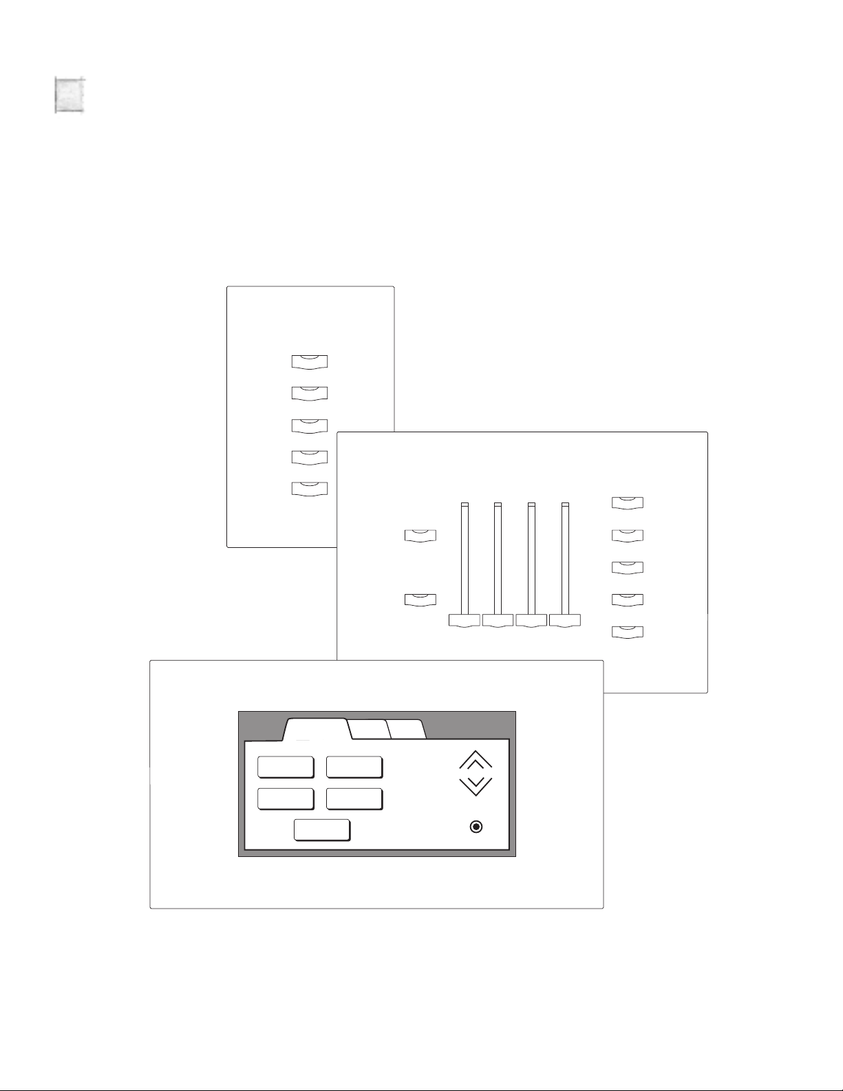
Control station overview
Unison control stations include Fader stations, Preset Recall stations, LCD
stations, Wireless Transmitters and several types of connector stations.
Portable versions of Fader, Preset Recall and LCD stations are also available.
Button and Fader functions
Control stations are operated with buttons and faders. Below is a list of
standard button and fader functions.
[Record]
Press [Record] to toggle the station in and out of Record mode. The [Record]
LED illuminates when Record mode is active.
Record mode also works with lighting control consoles using the DMX512
connector station. After setting the lighting look with the console, pressing
[Record] and a Preset button “snapshots” the look as a Preset.
[Manual]
Press [Manual] to activate the faders on a Fader station. The LEDs in the
[Manual] button and the Master and Zone faders illuminate when they are
active. The LCD station does not require a Manual button.
Zone fader
Move an active Zone fader up or down to adjust the light intensity in its
assigned light zone. The Zone fader’s LED illuminates when it is active.
Master fader
Slide the Master fader up or down when it is active to proportionally adjust all
light zone intensities. The Master fader LED illuminates when it is active. The
LCD station does not have a Master fader.
Preset buttons (including [Off])
Press a Preset button to recall a recorded set of light zone intensities. Light
zone intensities adjust to the new levels within a set interval (the standard is
one second.) The [Off] Preset sets zone intensities to zero, or to other security
or walkthrough settings. A Preset button’s LED illuminates when it is active.
[Raise]
Press and hold [Raise] to proportionally increase Preset light zone intensities.
The [Raise] LED illuminates when zone intensities are higher than their original
Preset levels.
[Lower]
Press and hold [Lower] to proportionally decrease Preset light zone intensities.
The [Lower] LED illuminates when zone intensities are lower than their original
Preset levels.
Preset Fade times
Many control station functions involve activating and changing Presets,
recorded sets of light zone intensities. Unison assigns a standard fade time of
one second to Preset activations. Your system may have customized fade
times assigned to some Presets.
Unison Station User Manual 11
Page 12

Fader station operation
A Unison Fader station adjusts lighting using Zone and Master faders or recalls
recorded lighting looks with Presets. You can use the faders to temporarily
adjust an active Preset, or set and record new Preset intensities to recall later.
➀ [Manual]
➁ [Record]
➂ Master fader
➃
Zone faders
Manual
➀
Master Zone 1 Zone 2 Zone 3
Preset 1
Preset 2
Preset 3
➄
Record
➁
➂
➃
Preset 4
Off
➄ Typical Preset buttons
To adjust intensities using faders
1. Press [Manual]
faders. The [Manual], Master fader and Zone fader LEDs illuminate.
2. Slide the faders up or down to adjust levels. Each Zone fader controls light
intensity in its assigned zone. The Master fader proportionally adjusts light
intensity for all zones.
. Intensities fade to levels that reflect the position of the
To record a Preset
1. Set light intensities
described above.
2. Press [Record]. The [Record] LED illuminates.
3. Press a Preset button. Current light intensities are recorded to the
button’s Preset, replacing previously recorded Preset intensities. The
Preset button LED illuminates when recording is complete.
to create the desired lighting look using the faders as
To take a “snapshot” from a DMX512 lighting control device
1. Set light intensities
lighting control device connected to the DMX512 Connector Station.
2. Press [Record]. The [Record] LED illuminates.
3. Press a Preset button. Current light intensities are recorded to the
button’s Preset, replacing previously recorded Preset intensities. The
Preset button LED illuminates when recording is complete.
12 Electronic Theatre Controls, Inc.
to create the desired lighting look using a DMX512
Page 13

To select a Preset
1. Press the desired Preset button
intensities recorded to its Preset. The button’s LED illuminates when the
Preset is active.
. The button recalls the set of light zone
To temporarily adjust Preset zone levels
1. Slide that zone’s fader up or down
lighting level. As it matches the zone level, the fader takes control from
the Preset. The fader LED illuminates and the Preset LED turns off.
2. Adjust zone intensity with the fader. To make the new levels permanent,
record them to a Preset.
until its position matches the current
To temporarily adjust (master) all Preset levels
1. Slide the Master fader all the way up
the Master fader activates and its LED illuminates.
2. Adjust intensities with the Master fader. To make the new levels
permanent, record them to a Preset.
. When it reaches the top of the slot,
Unison Station User Manual 13
Page 14

14 Electronic Theatre Controls, Inc.
Page 15

Preset 1
Raise
Lower
Preset 2
Preset 3
Preset 4
Off
➂ Typical Preset buttons
➀ [Raise]
➁ [Lower]
➀
➁
➂
Preset Recall station operation
The Unison Preset Recall station recalls recorded lighting looks with Preset
buttons. Standard Preset Recall stations have one, two, five, seven, or ten
buttons. In addition to Preset buttons, seven button Preset Recall stations
include [Raise] and [Lower] buttons to temporarily adjust the active Preset. For
a description of button functions, see
Control stations overview on
page 11.
To select a Preset
1. Press the desired Preset button
intensities recorded to its Preset. The button’s LED illuminates when the
Preset is active.
To master (raise or lower) a Preset
1. Press and hold [Raise]
intensities.
2. Press and hold [Lower] to proportionally decrease Preset light zone
intensities.
. The button recalls the set of light zone
to proportionally increase Preset light zone
Unison Station User Manual 15
Page 16

Zone WallsPresets 2Zones Presets
Preset 4
Off
Preset 2
Preset 1 Preset 3
➀ Page tab stack
➁ Typical page tabs
➂ Active page tab
➂➁➀ ➁ ➀
LCD station operation
The Unison LCD station represents buttons and faders with graphics. Use
these buttons and faders by touching their images on the LCD station’s
touchscreen.
The button and fader images are organized on individual control pages. A
single LCD station can have up to 30 control pages, displayed one at a time.
To display the page you want to use, touch its page tab.
Page tabs are located on the top edge of each control page. Each tab is labeled
with the name of its control page. Up to five page tabs can be displayed along
the top edge of the LCD screen at one time. When you touch a tab, the LCD
station displays the associated control page.
LCD stations with more than five control pages put the extra tabs in stacks in
the top corners of the display. Touching a stack hides the current set of tabs
and displays the next set on that side.
16 Electronic Theatre Controls, Inc.
Page 17

To find and select a desired control page
1. If the LCD faceplate is dark, touch the screen to turn on the backlight
.
2. Read the labels on the page tabs. If you see the tab for your desired page,
go to step 4.
3. To display the next set of page tabs touch either of the stacks. If you see
your desired page, go to step 4. If not, touch the stack again to display
another set of five tabs until you see your desired page. You can scroll
back and forth through the page tabs by touching the stacks on either side.
4. Select your desired page by touching its page tab. The desired control
page will appear.
The next five pages in the manual describe how to use the three standard LCD
control pages.
▼
Preset pages – Let you recall, record and adjust Presets.
▼
Zone pages – Let you adjust individual light zone intensities.
▼
Wall pages – Let you inform Unison of the current status of movable
partitions that divide rooms into smaller sections.
Custom pages provide customized combinations of all the available controls.
The appearance of a custom page will vary according to its function.
Unison Station User Manual 17
Page 18

WallsZonesPresets
Preset 4
Off
Preset 2
Preset 1 Preset 3
➀ Presets page tab
➁ Typical Preset buttons
➃ [Lower]
➂ [Raise]
➄ [Record]
➀
➁
➂
➃
➄
LCD station Preset page
The Preset page displays up to five Preset buttons (including [Off]) you use to
recall recorded light levels. It also contains [Raise] and [Lower] buttons to
adjust Preset light levels, and a [Record] button to record new Preset settings.
To select a Preset
1. Touch the Presets tab
2. Press the desired Preset button. The button recalls the set of light zone
intensities recorded to its Preset. The active Preset button is highlighted.
. The Preset control page appears.
To record a preset
1. Touch the Zones tab
2. Adjust the zone faders to set the desired lighting look.
3. Touch the Presets tab to return to the Preset page.
4. Touch the Record button. Record appears over the button, indicating the
station is in Record mode. (Record mode deactivates after seven
seconds.)
5. Touch the desired Preset button
recorded to the button’s Preset, replacing previously recorded Preset
intensities. The button is highlighted when recording is complete.
. The Zones page appears.
. Current light zone intensities are
To master (raise and lower) an active Preset
1. Touch the Presets tab
2. Touch and hold [Raise] to proportionally increase Preset light zone
intensities.
18 Electronic Theatre Controls, Inc.
3. Touch and hold [Lower] to proportionally decrease Preset light zone
intensities.
. The Preset page appears.
Page 19

To take a “snapshot” from a DMX512 lighting control device
1. Set light zone zone intensities
DMX512 lighting control device connected to the DMX512 connector
station.
2. Touch the [Record] button. Record appears over the button, indicating the
station is in Record mode. (Record mode deactivates after seven
seconds.)
3. Touch the desired Preset button. Current light zone intensities are
recorded to the button’s Preset, replacing previously recorded Preset
intensities. The button is highlighted when recording is complete.
to create the desired lighting look using a
Unison Station User Manual 19
Page 20

LCD station Zones page
WallsPresets
75
Zone 4
Zones
50
Zone 3
100
Zone 2
25
Zone 1
➀ Zones page tab
➃ Raise arrow
➄ Lower arrow
➁ Intensity bar
➂ Intensity percent
➀
➁
➂
➃
➄
The Zones page displays up to four Zone faders you can use to adjust
individual light zone intensities directly.
To select the Zones page
1. Touch the Zones tab
. The Zones page displays up to four zone faders.
To gradually adjust light zone intensities
1. Touch the Raise or Lower arrow of the desired fader
percentage displays change to reflect intensity adjustments.
. The bar and
To quickly adjust light zone intensities
1. Touch the intensity bar of the desired fader
instantly sets light zone intensity to 0, 25, 50, 75, or 100 percent,
depending where on the bar you touch. The bar and percentage displays
change to reflect intensity adjustments.
. Touching the intensity bar
20 Electronic Theatre Controls, Inc.
Page 21

Controlling partitioned spaces
Presets
Zones Walls
Wall 1 Wall 2
Wall 3 Wall 4
➀ Walls page tab
➂ Open wall
➁ Closed wall
➀
➂
➁
If your facility has large rooms that can be partitioned into smaller sections by
movable walls, you can control lights in each section individually, or you can
open the walls and control the lights for the room as a whole.
On the LCD station’s Walls page, a wall is represented by a line with the wall’s
name underneath. A dashed line indicates an open wall and a solid line means
the wall is closed. If the line is solid, the controls in the sections divided by that
wall are separated and operate independently. If the line is dashed, the
controls are joined and operate together.
To change a wall between open and closed
1. Touch the Walls tab
2. Touch the wall’s line. The line toggles between dashed (open) and solid
(closed).
A Unison system can also use partition sensors to detect when walls are open
or closed. The system will automatically set your control stations to work
together or separately based on the actual state of the walls. The state of walls
using partition sensors can still be switched between open and closed by
touching their wall symbols on the LCD Wall page.
. The Walls page appears.
Unison Station User Manual 21
Page 22

Wireless Transmitter operation
➂ Typical Preset buttons
➀ [Raise]
➁ [Lower]
➂
➀
➁
The Unison Wireless Transmitter is a handheld control device that lets you
select, raise, and lower Presets anywhere within 40 feet of the ceiling
mounted infrared receiver.
Objects in the line of sight between the Wireless Transmitter and its receiver
can block infrared signals and reduce effective control range. Bright lights near
the receiver, especially compact fluorescents, can also cause interference.
Point the transmitter directly at the receiver during use to ensure consistent
performance.
The standard Wireless Transmitter lets you recall and adjust Presets. Standard
Wireless Transmitters have [Raise], [Lower], and five Preset buttons (including
[Off]). These buttons function identically to their counterparts on other control
stations. See
button’s function.
Control station overview
on page 11 for descriptions of each
To select a Preset
1. Press the desired Preset button. The button recalls the set of light zone
intensities recorded to its Preset.
To master (raise or lower) an active Preset
1. Press and hold [Raise] to proportionally increase Preset light zone
intensities.
2. Press and hold [Lower] to proportionally decrease Preset light zone
intensities.
22 Electronic Theatre Controls, Inc.
Page 23

Portable connector station
The Unison Portable station connector lets you connect portable controls to
the system. To use a portable control, attach the control cable to the
Connector station. The station should be ready to operate within 30 seconds.
PC connector station
The Unison PC connector station connects a personal computer equipped
with Unison Light Manager software to the Unison Architectural processor.
Connect a DB 9 serial cable between the PC Connector station and the RS232
(serial) port of your personal computer. For information about using a Unison
Light Manager equipped PC with a Unison system, consult the
User Manual
or contact ETC.
Light Manager
DMX512 connector station
The Unison DMX512 connector station lets you connect DMX512 devices like
theatrical lighting control consoles and show controllers to a Unison system.
To use DMX512 devices with the station, attach the DMX512 cable to the
DMX512 connector station. Your system must be configured for DMX512
connections.
Unison systems can also record Presets by taking a “snapshot” of a lighting
look set by a lighting console or other DMX512 device connected to the
DMX512 Connector Station. After the look is set, the snapshot is recorded in
the same fashion as a regular Unison Preset.
Link Power Supply
The Unison Link Power supply provides operating voltage for Unison controls.
It should be located on the wall next to your dimmer rack.
➀ 12 Vdc (green LED)
➁ Reset switch
➂ Link power (yellow LED)
➀➁➂
Unison Link \ 12VDC Supply
Amber: LinkPower
Green: 12VDC
Electronic Theatre Controls
For Assistance call (608) 831-4116
Unison Station User Manual 23
Page 24

,,,
,,,
,,,
chapter 3
system
maintenance
Cleaning dimmer rack air filters
The air filter on your dimmer should be cleaned every six months, more often
if your system operates in a dusty environment. You can remove the air filter
for cleaning.
1. Open the dimmer rack door. The air filter is mounted on the inside of the
door, held in on the bottom by a metal lip.
2. Slide the filter up about 1/2 inch until the filter base clears the top edge of
the lip. Tilt the filter slightly so the base is out far enough to clear the
retaining lip and slide the filter down and out.
3. Vacuum or blow out the dust in an appropriate place. (Not next to the
dimmer rack.) You can wash the filter under clear tap water, but it must
be completely dry before you reinstall it. Do not use soap or other
chemicals to clean the filter.
4. Slide the top of the filter back up into the slot at the top of the door until
the base clears the metal retaining lip on the bottom of the door.
5. Let the filter drop back into place and close the door.
24 Electronic Theatre Controls, Inc.
Page 25

Vacuuming out dimmer racks
OFFOFFOFFOFF
12
11
6
5
➂ CEM grill
➁ SCR grill
➀ Choke vent
➀
➁
➂
Even in a dimmer rack with an effective air filter, air seal leaks, open door
operation and other factors will let in some dust. You should inspect your
dimmer rack when you clean the air filter and vacuum the front of the dimmer
modules if necessary.
1. Open the door and look at the modules’ air vents. If dust is thick enough
to hide the paint color, you should vacuum the front of the modules.
2. Leave the modules inside the rack. Most dust collects on the dimmer
choke vents and SCR grills of the dimmer modules. Removing modules
exposes the phase voltage buss bars inside the rack.
WARNING! Phase voltages inside the rack can be deadly. Do not remove
rack modules unless you are a qualified technician.
3. Use a narrow vacuum cleaner nozzle to remove dust from the dimmer
modules. Pay particular attention to the dimmer choke vents, the SCR
grills and the CEM grill. Do not push or blow debris into the modules or
rack interior.
4. When you are finished, close the door.
Unison Station User Manual 25
Page 26

Cleaning control station faceplates
All control faceplates (except the LCD control)
Control station faceplates, with the exception of the LCD touchscreen, can be
cleaned with ammonia-based glass and hard surface cleansers. Do not use
abrasive cleansers.
1. Dampen a soft clean cloth with cleanser. Do not spray cleanser directly on
the control faceplate.
2. Clean the faceplate with the cloth.
LCD control faceplate (including touchscreen)
LCD control stations should be cleaned with clean absorbent cotton cloth,
moistened with water or alcohol only. Do not use detergent, abrasives, or
ammonia-based cleaners.
1. Dampen the cloth with alcohol or water only. Do not spray alcohol or water
directly on the control faceplate.
2. Clean the faceplate and touchscreen with the cloth.
26 Electronic Theatre Controls, Inc.
Page 27

Replacing batteries in the Wireless Transmitter
1. Press lightly on the front edge (see illustration) and pull out the access
cover.
2. Remove the old batteries.
3. Install two AAA alkaline batteries oriented with the diagram inside the
battery compartment.
4. Slide the cover back over the battery compartment until the clip catches.
Unison Station User Manual 27
Page 28

Chapter 4
Contacting
If you have a Unison system problem, please fill out a photocopy of this
problem report form before calling ETC Technical Services. This
information will help ETC correct the problem quickly and effectively.
The toll-free Technical Services number is 800 775 4382.
Technical
Services
If any of the questions on the form seem hard to answer, please refer to
the explanations on the following pages. Each question is explained
along with instructions on how to find the answer you need.
Unison Lighting Control System – Problem Report Form
System Information
Today’s Date: _________________________________ Job Name: ________________________________________
Your Name: __________________________________ Job Number: ______________________________________
Phone Number: _______________________________ Software Version: _________________________________
System Description:________________________________________________________________________________
___________________________________________________________________________________________________
___________________________________________________________________________________________________
___________________________________________________________________________________________________
Problem conditions:
1. Are the wall stations working?
▼ Do the stations control lights?
▼ Do station button and fader LEDs turn on/off properly? ❏ Yes ❏ No
▼ Do station LEDs “chase” when a button is pressed? ❏ Yes ❏ No
▼ Do wall stations appear to be off (no response)? ❏ Yes ❏ No
2. Can you enter the Unison setup menu on the CEM? ❏ Yes ❏ No
3. If you can't enter the menu, does resetting the system change this? ❏ Yes ❏ No
4. If you can enter the menu, is there a configuration present? ❏ Yes ❏ No
5. If there is no configuration, does resetting change this? ❏ Yes ❏ No
6. Have you been downloading configurations recently? ❏ Yes ❏ No
7. Please describe any events that might be related to the system malfunction: _________________________
___________________________________________________________________________________________________
___________________________________________________________________________________________________
❏ Yes ❏ No
___________________________________________________________________________________________________
28 Electronic Theatre Controls, Inc.
Page 29

System Information
1. Date: Enter the date you will be calling ETC Technical Services with the
problem.
2. Your name: Write in the name of the best person for Technical Services
to contact to follow up on your request.
3. Phone Number: Enter the phone number Technical Services should call to
follow up on your request. Please include area code and extensions.
4. Job Name: Check the system riser diagram that came with your system.
The top line should have the system name. If you cannot find the diagram
title, write the name of your building in this blank.
5. Job Number: Check the system riser diagram that came with your
system. The job number should be below the system name. If you cannot
find the job number, don’t write anything in this blank. Ask the Technical
Services person to help you find the job number when you call ETC.
6. Software Version
it here.
If you don’t know the software version of your configuration, you can find
it on the first line of the Unison Setup menu. To enter the Unison Setup
menu, follow the procedures for answering Question 2,
Unison Setup menu on the CEM?
7. System Description: Consult your riser diagram and enter the number of
control stations, rooms and Presets in your system. Indicate whether you
use Light Manager software. Also include any special features like
Snapshot, DMX512 or MIDI connections. Answer as many of these
questions as you can, but don’t worry if you cannot answer them all. Your
Technical Services representative will help you fill in the blanks.
: If you know the software version for your system, enter
Can you enter the
on page 31
.
Unison Station User Manual 29
Page 30

Problem conditions
Fill out the problem conditions starting with the first question and working
your way to the end. When a question requires you to check a separate Unison
component, you will be directed where to go and what to do by the
instructions.
1. Are the wall stations working? Most problems with an architectural
lighting control system are detected when a control station won’t work.
Preset Recall and Fader stations have built-in feedback features that can
tell you a lot about what is happening in your system.
▼ Do the stations control lights? Press several different Preset buttons or
vary zone light intensities with the Zone or Master faders. Observe if
the light intensities change normally.
▼ Do station button and fader LEDs turn on/off properly? To test a Preset
button LED, watch it while you press the button. If the LED was off
when you pressed the button, it should turn on. If the button LED was
on, it should turn off. Try this with different Preset buttons to determine
if their LEDs are responding properly. To test fader LEDs, press
[Manual]. The fader LEDs should turn on. Press [Manual] again and the
LEDs should turn off.
▼ Do wall station LEDs run the self test chase? Push a button on a Preset
Recall or Fader station. Under some conditions, these stations respond
by turning all their button and fader LEDs on and off one at a time. This
is the self test chase. Pushing another button, or the same button again
will repeat the chase. When stations run the self test chase, it indicates
the station has lost its connection to the Architectural Processor.
▼ Do wall stations appear to be off (no response)? Pushing buttons and
moving faders on an unresponsive station will not change light
intensities or turn LEDs on or off.
30 Electronic Theatre Controls, Inc.
Page 31

To answer the next four questions, find the Unison Architectural Processor,
which is located in a Sensor Installation Rack Control Electronics Module
(CEM). Your Sensor Installation Rack will usually be located in a utility room or
electrical cabinet. After locating the rack, open the door to find the CEM.
Note: If you have multiple Sensor racks, you will have to determine which one
contains the Architectural Processor. To find it, look for the Unison sticker
under the Sensor logo on the rack door. If you cannot find a rack with the
sticker, consult your system drawings to determine which Sensor rack
contains your Architectural Processor.
The CEM contains the Architectural Processor for your Unison system.
Access the Unison setup menu through the CEM keypad and LCD display.
➀ LCD display
➁ [Setup]
➂ Numeric keypad
➃ [Enter]
Unison Menu (1.2)
[Setup]
LCD display
Note: If you make a keypad mistake and want to start over, press [Setup]
9
8
7
Dimmer
About
Backup
Setup
A/B
5
4
➂
2
1
0
Setup 1–Dimmer
2–Rack 3–System
s
nsor
E
➀
➁
2. Can you enter the Unison Setup menu on the CEM
Exit
6
Next
3
Thru
Clear
At
OA
OB
ETCLink
OC
ResetEnter
➃
? Access the Unison
.
setup menu through the CEM keypad and LCD display.
To enter the Unison menu:
Press [Setup] [3] [Enter]. If the CEM LCD display matches the LCD display
↕
example to the left, you have entered the Unison Setup menu.
Note: The number in parenthesis on the top line of the Unison Setup
display is the software version number for your system. Enter this number
in the Software Version blank under on the System Information section of
the form if you have not done so already.
3. If you can’t enter the menu, does resetting the system change this?
To reset the system, press [Reset] on the CEM and wait for 30 seconds.
Then repeat the procedure to access the Unison Setup menu from
question 2.
4. If you can enter the menu, is there a configuration present?
The configuration contains Room, Control, and other data about your
system. If the configuration is present, this data is available to your
Architectural Processor. By checking for system data in the Setup
Information menu, you can determine if the configuration is present.
▼ To access the Setup Information menu from the Unison Setup menu
press [Enter] [↑] [Enter].
▼ To access the Setup Information menu after pressing [Setup] to start
over, press [Setup] [3] [Enter] [Enter] [↑] [Enter].
Setup Information
[Sta: 15 Con: 15]
LCD display
Unison Station User Manual 31
The second line of the Setup Information menu shows how many wall
stations are in the configuration and how many are linked to the
Architectural Processor. If the number after [Sta: is not zero, there is a
configuration present.
Page 32

Setup Information
[Sta: 15 Con: 15]
LCD display
5. If there is no configuration, does resetting change this?
To reset the system, press [Reset] on the CEM and wait for 30 seconds.
▼ To access the Setup Information menu, press [Setup] [3] [Enter]
[Enter] [↑] [Enter].
The second line of the Setup Information menu shows how many wall
stations are in the configuration and how many are linked to the
Architectural Processor. If the number after [Sta: is not zero, there is a
configuration present.
6. Have you been downloading configurations recently?
If you or anyone else has installed a new version of your configuration
software or edited rooms, macros or time clock events using Light
Manager software, you have downloaded configurations to your
Architectural processor.
7. Please describe any events that might be related to the system
malfunction:
Events that happened to or around your Unison system before the
problem occurred may have affected its performance. Some example:
Have you experienced recent power outages or lightning strikes?
Has there been building construction/repairs near your system?
Did the problem occur while someone was downloading a configuration
or using Light Manager for live control or system monitoring?
Did the problem happen when someone was using the system to adjust
light zone intensities, or during a period of inactivity (night or weekend)
when the system was not in use?
Could the problem be related to a macro or time clock activation?
32 Electronic Theatre Controls, Inc.
Page 33

glossary
A
Architectural Processor
The Architectural Processor is the computer that runs a Unison lighting control
system. It interprets control station inputs, transmits light zone intensities to
dimmer racks, and maintains system calendar and macro functions. A
processor can be integrated into a dimmer rack or installed into a separate
enclosure.
Astronomical time clock
The internal clock in a Unison CPU. It keeps local time and date as well as
calculating sunrise and sunset times throughout the year based on
geographical position, elevation, time zone, and Daylight Savings.
B
Binding
Binding is the linking of a control station’s signal and its room and zone
assignments in the Architectural Processor.
Buttons
C
D
Buttons are used for input on Preset Recall, Fader and Wireless Transmitter
control stations. Button functions are stored in the Unison Architectural
Processor.
Configuration
The system-specific information used by the Architectural Processor to
control lighting. Configurations are downloaded to the Processor from a
PCMCIA card or by a personal computer connected to a PC connector station.
Connector station
A connector station connects other devices to the network. The Portable, PC
and DMX512 connector stations are examples.
Control station
A control station sends information to the Unison processor. Control stations
include Wall, Connector, Wireless Transmitter, and Portable stations.
Dimmer
A dimmer is a device that varies light zone intensity in response to control
station commands.
DMX512
DMX512 is a communication standard developed for theatrical lighting control.
Unison processors can accept and process DMX512 input from theatrical
lighting control consoles and output DMX512 to control dimmers.
Unison Station User Manual 33
Page 34

E
Event
A Preset or macro activation.
F
Fade Time
Fade time is the set interval for light zone intensity levels to change when a
Preset is activated.
Fader
A fader is a sliding control that allows you to raise or lower levels. LCD station
faders are represented by bar graph symbols.
Fader Station
A Fader station uses linear potentiometers (sliders) as well as buttons to
control light zone intensities.
I
Intensity
The brightness or output level of fixtures in a light zone.
L
LCD Station)
M
P
The Unison LCD control station controls lighting with a high resolution
touchscreen LCD to display buttons, sliders and other control images.
Light Manager
The Unison configuration program. It is used to create and edit Unison
configurations, including writing macros and programming time clock events.
Light zone
One or more light fixtures that are controlled together.
Macro
A macro is a recorded set of commands programmed to play back at a
scheduled time or activated by a control station.
Master fader
A master fader proportionally raises or lowers multiple light zone intensities.
Preset Recall station
A Preset Recall station controls light zone intensities by recalling and adjusting
Presets using button input.
Preset
A Preset is a recorded set of light zone intensities, including a programmed
fade time (default is one second).
Preset button
A Preset button is a button or LCD symbol that recalls an assigned Preset
when activated.
34 Electronic Theatre Controls, Inc.
Page 35

R
S
T
W
Room Combine
Room Combine allows sections of a divided room to be controlled together
based on the position of movable partitions.
Room
The basic unit of the space controlled by a Unison system. Rooms may be
divided into sections.
Section
A section is a division of a room – defined by walls, partitions or use.
System
The equipment and programming needed for self-contained control of
architectural lighting and associated devices in a designated space.
Time clock
See astronomical time clock.
Wall
A wall is a movable partition that divides a room into sections.
Wall station
A wall station is a control station designed for wall mounting.
Z
Zone
A single Unison light intensity level, usually applied to one or more light
fixtures that are controlled together.
Zone fader
A fader that controls a single light zone.
Unison Station User Manual 35
Page 36

Electronic Theatre Controls
North America Europe Asia
3030 Laura Lane 5 Victoria Industrial Estate • Victoria Road Room 1619-20 • 16/F Metro Centre II • 21 Lam Hing Street
Middleton, Wisconsin 53562 • USA London W3 6UU • England Kowloon Bay • Hong Kong
Tel: (+1) 608 831 4116 • Fax: (+1) 608 836 1736 Tel: (+44) 181 896 1000 • Fax: (+44) 181 896 2000 Tel: (+852) 2799 1220 • Fax: (+852) 2799 9325
World Wide Web: http://www.etcconnect.com • Email: mail@etcconnect.com
36 Electronic Theatre Controls, Inc.
Copyright 1996. Specifications subject to change. 7081M1001. Revised 10/96.
 Loading...