

Page 1
ETC Installation Guide
Unison® Heritage Contact Station
Corporate Headquarters Middleton, WI, USA Tel +608 831 4116 Service: (Americas) service@etcconnect.com
London, UK
Tel +44 (0)20 8896 1000 Service: (UK) service@etceurope.com
Rome, IT
Tel +39 (06) 32 111 683 Service: (UK) service@etceurope.com
Holzkirchen, DE
Tel +49 (80 24) 47 00-0 Service: (DE) techserv-hoki@etcconnect.com
Hong Kong
Tel +852 2799 1220 Service: (Asia) service@etcasia.com
Web: etcconnect.com
© 2018 Electronic Theatre Controls, Inc.
Product information and specifications subject to change. ETC intends this document to be provided in its entirety.
7181M2111
Rev B Released 2018-04
Overview
The Unison Heritage Contact Station (model# UHCI-4) provides convenient
interface and integration to external devices such as photo cells, motion sensors,
fire alarm system, etc., by sending and receiving contact closures.
This station provides four contact (switch) input and four lamp output
connections. Closures are configurable for either maintained or momentary
operation.
Installation
The Contact Station ships with a termination kit for use with Belden 8471 (or equivalent wire), a
LinkConnect power pigtail, ground wire pigtail, receptacle spacers, and all required wire termination
connectors for installation.
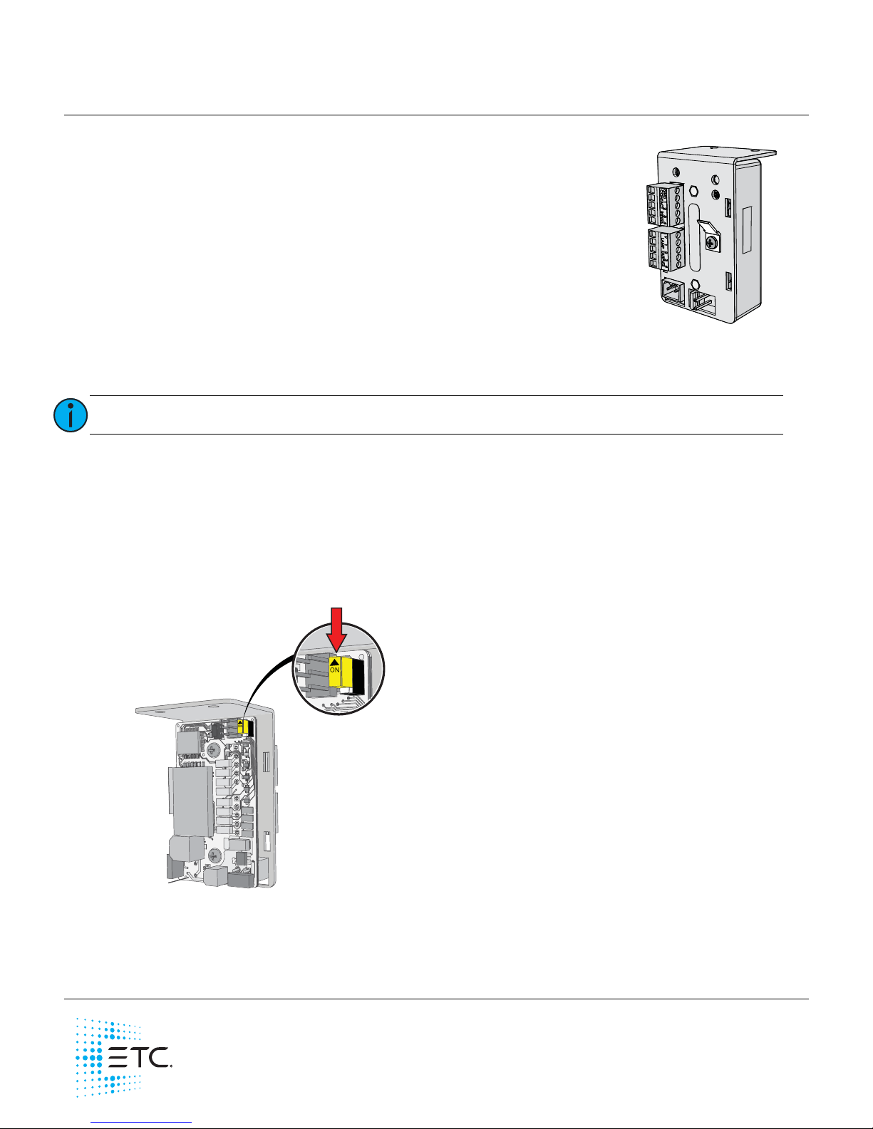
Chase Enable / Disable
After powerup, when the station is unbound from the Paradigm Architectural Control Processor (P-ACP),
the contacts will cycle as indication to the user that the station is unbound.
If this chase behavior is undesired, remove the rear cover and slide the chase enable switch to the off
position.
Replace the cover and continue installation.
Note:
Installation should follow local codes and standard practices.
neuron ID
Slide switch Off to disable
chase behavior
Page 2
ETC Installation Guide
Heritage Contact Station
Unison® Heritage Contact Station Installation Guide Page 2 of 4 ETC
Wiring Requirements
The WAGO LEVER-NUTS®, provided in the termination kit, accepts 24-12 AWG (0.2 - 4 mm2) wires.
Connect Wiring
1: Pull all required wiring (data + and data -) to the installation location. As needed, pull an additional
ESD ground wire (required when wiring is not installed in grounded metal conduit.
Purpose
Recommended
Wire Type
Notes
LinkConnect
Belden 8471
(or approved equal)
LinkConnect is a bidirectional protocol that uses one pair of wires
(data+ and data- Class 2 installation).
Auxiliary Power
(24 Vdc)
2 each 16 AWG
(1.5 mm
2
) wires
ESD Ground
1 each 14 AWG
(2.5 mm
2
)
Required when wiring is not installed in grounded metal conduit
Contact Inputs
2 each 16 AWG
(1.5 mm
2
) wires
Two wires are required per switch (Contact Input and Common),
supporting up to 1,000 feet (305 m) of 16 AWG wire between the
input and the common.
Lamp Outputs
2 each 16 AWG
(1.5 mm
2
) wires
Two wires are required per output (Lamp Output and V out),
supporting up to 1,000 feet (305 m) of 16 AWG wire between the
V out and lamp output.
Note:
NEC Class 2 product to be wired in accordance to NEC Article 725 and local jurisdiction
requirements.
N
e
u
r
on ID
Serial #
LinkConnect
pigtail
ESD Ground
pigtail
Auxiliary Power
pigtail
Page 3

ETC Installation Guide
Heritage Contact Station
Unison® Heritage Contact Station Installation Guide Page 3 of 4 ETC
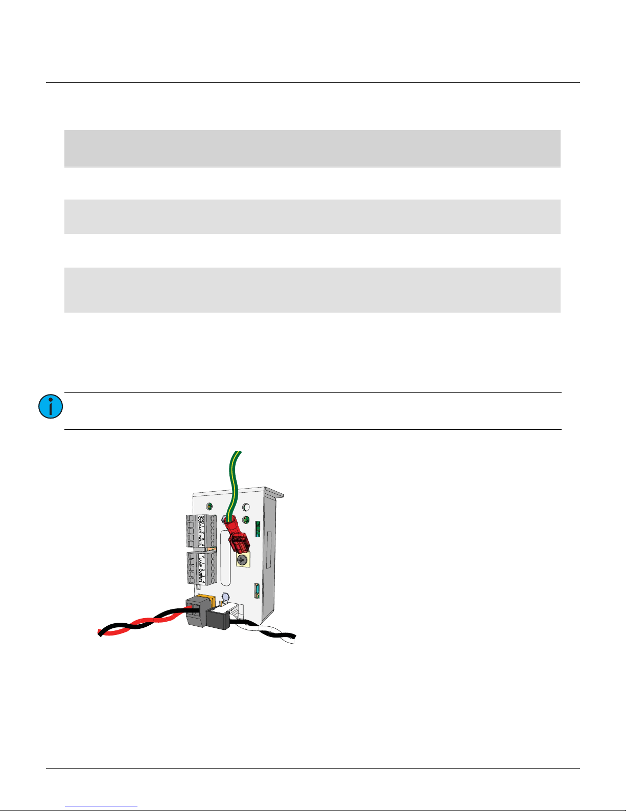
2: Connect station ESD ground wire pigtail.
a: Strip 3/8” (9-10 mm) of insulation from the ends of the station ground wire pigtail, provided in
the termination kit, and the incoming ground wire.
b: Use one WAGO connector, provided in the termination kit, to connect the station ESD ground
pigtail and the incoming ground. For stations using grounded metal conduit, connect the ground
pigtail to the metal switch box ground location.
c: Install the ESD ground wire pigtail Faston connector to the spade terminal to the station.
3: Terminate and connect LinkConnect wires. LinkConnect is topology free and polarity independent.
You may install LinkConnect in any combination of bus, loop, star or home-run. The total combined
length of a LinkConnect wire run (using Belden 8471, or equal) may not exceed 1,640 feet (500 m)
with a maximum distance of 1,312 feet (400 m) between any two devices.
a: Strip 3/8” (9-10mm) from the ends of each power pigtail wire, provided in the termination kit,
and the installed control wires.
b: Use the provided WAGO connectors to connect the LinkConnect power pigtail wires and the
installed Belden 8471 control wires. One WAGO should be used for the white wire pair (data +)
and one for the black wire pair (data -). Open the terminal levers on the WAGO connector and
insert the installed Belden 8471 wire and the lead from the LinkConnect power pigtail into the
terminals then close the levers.
c: Install the two pin connector from the LinkConnect power pigtail to the mating receptacle on the
station electronics.
4: Terminate and connect Auxiliary Power (24 Vdc) wires.
a: Strip 3/8” (9-10 mm) from the ends of each auxiliary power pigtail wire, provided in the
termination kit, and the installed power wires.
b: Use the provided WAGO connectors to connect the auxiliary power pigtail wires and the installed
16 AWG (1.5 mm
2
) wires. One WAGO should be used for the red wire pair (positive) and one for
the black wire pair (negative). Open the terminal levers on the WAGO connector and insert the
installed wire and the lead from the power pigtail into the terminals then close the levers.
c: Install the two pin connector from the auxiliary power pigtail to the mating receptacle on the
station electronics.
Page 4

ETC Installation Guide
Heritage Contact Station
Unison® Heritage Contact Station Installation Guide Page 4 of 4 ETC
5: Connect Contact Input (Switch) wiring to the five-position connector labeled for Contact Inputs.
a: Strip 1/4” (6 mm) from the ends of each Contact Input wire and the Ground wire that will
terminate to the five-position connector.
b: Strip 3/8” (9-10 mm) from the ends of each reference Ground wire to be bussed into a WAGO
connector.
c: Loosen the terminal screw for each required termination and insert the wires into the
corresponding terminals. Tighten the screws firmly onto the wires.
d: Use a WAGO connector to bus the reference Ground wires. Open the terminal levers on the
WAGO connector and insert one wire per terminal, including a lead from the Contact Input
connector Ground terminal, then close the levers.
6: Connect Lamp Output wiring to the five-position connector labeled Lamp Outputs.
a: Strip 1/4” (6 mm) from the ends of each Lamp Output wire and the V out wire that will terminate
to the five-position connector.
b: Strip 3/8” (9-10 mm) from the ends of each V out wire to be bussed into a WAGO connector.
c: Loosen the terminal screw for each required termination and insert the wires into the
corresponding terminals. Tighten the screws firmly onto the wires.
d: Use a WAGO connector to bus the V out wires. Open the terminal levers on the WAGO connector
and insert one wire per terminal, including a lead from the Lamp Outputs connector V out
terminal, then close the levers.
7: Attach the station to the installation location.
Note:
Plan your wiring accordingly.
Only one Ground (common) terminal is provided on the Contact Input connector. If
multiple switch inputs are required for your installation, additional reference Ground
connections must be bussed together using a WAGO connector.
Note:
The lamp voltage conducts from “V” to the lamp outputs. Connect the anode to the “V”
and the cathode to the lamp output connection.
Note:
Plan your wiring accordingly.
Only one Voltage out (V) terminal is provided on the Lamp Outputs connector. If multiple
lamp outputs are required for your installation, additional V out connections must be
bussed together using a WAGO connector.
Note:
The Paradigm Architectural Control Processor (P-ACP) to which this Heritage station is
connected must learn, or be told, the station hardware address (a.k.a. neuron ID). This
ID can be manually entered into the configuration (as labeled on the front of the station)
using LightDesigner software, or can be identified by the connected Paradigm ACP using
the “Connect a Device” menu.
Reference the Unison Paradigm Architectural Control Processor Configuration Manual;
specifically the section on Arch Setup Menu, LonWorks Connections.
 Loading...