

Page 1
ETC Installation Guide
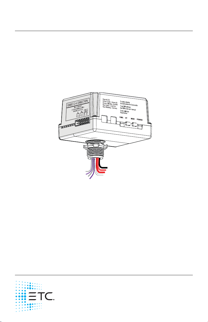
Unison Foundry™ 0–10V Controller
Overview
The Unison Foundry 0–10V Controller provides fully-rated 20A relays for
switched power control with 0–10V dimming for compatible fluorescent
ballasts and LED drivers. The 0–10V Controller provides two outputs of
control that can be wired to individual fixtures or used for zone control. Each
output can be configured to a separate DMX address, or both outputs can be
controlled in unison by setting the 0–10V Controller to single-channel mode
Channel Mode
(see
on
page 8
).
Control connected loads from any DMX control device. Configure the 0–10V
Controller either remotely via RDM (using a tool like ETC Net3 Concert) or
locally on the controller. See
Configure the 0–10V Controller
on
page 8
Specifications
Ambient Environment
For indoor use only. Rated for plenum use.
• 32°F to 104°F (0°C to 40°C) operating temperatures in 5–95% noncondensing humidity.
Corporate Headquarters Middleton, Wisconsin, USA Tel +608 831 4116
Service (Americas) service@etcconnect.com
London, UK Tel +44 (0)20 8896 1000 Service: (UK) service@etceurope.com
Rome, IT Tel +39 (06) 32 111 683 Service: (UK) service@etceurope.com
Holzkirchen, DE Tel +49 (80 24) 47 00-0 Service: (DE) techserv-hoki@etcconnect.com
Hong Kong Tel +852 2799 1220 Service: (Asia) service@etcasia.com
Web: etcconnect.com
specifications subject to change.
7179M2120 Rev B Released 2017-12
© 2017 Electronic Theatre Controls, Inc.
ETC intends this document to be provided in its entirety.
Product information and
.
Page 2

ETC Installation Guide
0–10V Controller
Electrical Specification
The 0–10V Controller Supports:
• Power input 120–277VAC, 60 Hz
• Maximum load rating is 20A (total connected load)
Note:
• Independent control for 0–10V fluorescent ballasts and/or LED drivers,
each is capable of sinking 100mA
Supported Load Types (all voltages):
• 20A fully-rated relay for use with general purpose, tungsten,
fluorescent, and LED lighting loads.
The maximum load on the 0–10V Controller can be split
between the two relay outputs in any combination
required for the installation, but cannot exceed 20A
total connected load for the controller.
Compliance
• UL and cUL listed
• Conforms to UL 916 (Energy Management Equipment) and UL 2043
(Plenum rated)
0–10V Controller Page 2 of 16 ETC
Page 3
ETC Installation Guide
0–10V Controller
Prepare for Installation
The 0–10V Controller is designed for mounting directly to an electrical
junction box or panel (provided by others) at the electrical lighting load,
upstream of the load in the circuit.
Note:
If your installation requires Class 2 wiring to be installed
in separate conduit, a voltage barrier installation box is
available from ETC. Order ETC part number 7187A1000.
DMX Control Wiring
The 0–10V Controller connects to a DMX512-A source (provided by others)
for control.
DMX wiring runs can be daisy chains of up to 32 devices with no Y’s or loops.
Each DMX daisy chain must be terminated for proper control performance
(see
Terminate DMX
ETC recommends using Belden 9729 (or approved equivalent) Class 2 wire.
Belden 1583A or equivalent Cat5, Cat5e, or Cat 6 UTP wire is also acceptable
when properly shielded or installed in grounded metal conduit and
connected using the Cat5 IDC termination kit (ETC part number
4100A1013). This termination kit is not provided with the 0–10V Controller.
A voltage barrier installation box (part number 7187A1000) is available for
installations where DMX control wiring is installed in grounded metal
conduit. Contact ETC to purchase termination kits or voltage barrier
installation boxes if required.
The total combined length of a DMX wire run (using Belden 9729 or
equivalent) may not exceed 1,000 ft (300 m).
Note:
on
page 5
).
All control wiring should be installed and terminated by
a qualified installer and should follow standard wiring
installation practices.
Leave approximately 10 in (255 mm) of wiring available
for connection and to allow slack for future service
.
needs
Note:
0–10V Controller Page 3 of 16 ETC
For more information on DMX control wiring
requirements, see these and other Support Articles at
etcconnect.com:
• etcconnect.com/Support/Articles/DMX-512-Info.aspx
• etcconnect.com/Support/Articles/DMX-Over-Cat5.aspx
Page 4
ETC Installation Guide
0–10V Controller
Installation
Installation should follow all local codes and standard electrical practices.
Ensure that the junction box is clean and free of obstructions and that all
wiring is installed correctly.
WARNING:
WARNING:
1: Locate the circuit breaker panel and turn off the power to the lighting
circuit.
2: To gain access to the line voltage wiring, remove the cover plate and
other hardware from the junction box at the load.
3: Mount the 0–10V Controller to the exterior of the junction box or
panel using the 1/2” threaded nipple. Use the provided 1/2” conduit
locknut to secure the 0–10V Controller to the junction box or panel.
Note:
Risk of electric shock! This device utilizes high voltage
and should only be installed by a qualified installer or
electrician. Follow all local codes for installation. Before
terminating the AC power wiring verify that the main
breaker is in the off position and follow the proper
lockout/tag out procedures per NFPA Standard 70E.
For indoor use only! Must install to an electrical
junction box or wire way.
Follow all local code requirements for terminating wire.
• Notice that the harness wires on the controller are
pre-stripped for your installation convenience.
• Use appropriately sized wire nuts (not provided) to
secure each termination.
0–10V Controller Page 4 of 16 ETC
Page 5
ETC Installation Guide
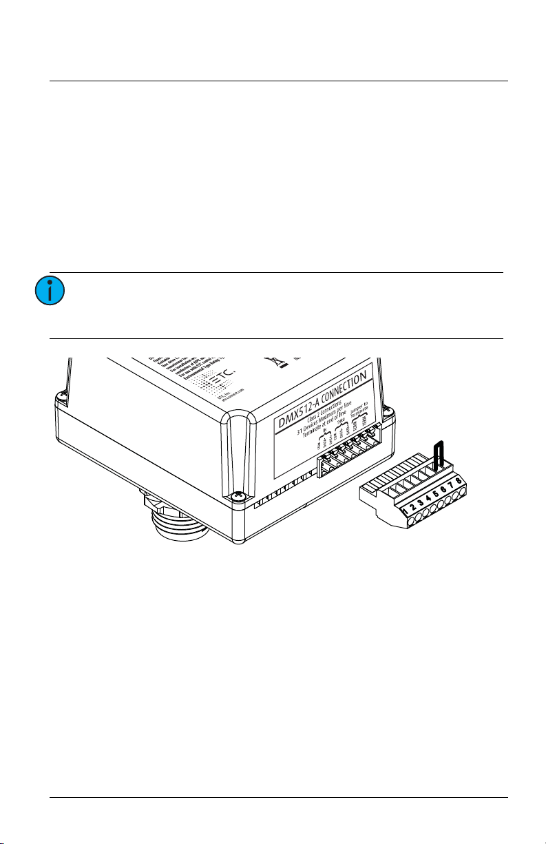
Wire jumper
0–10V Controller
Connect DMX
1: Pull wiring to the junction box.
2: Terminate the DMX cable by following the steps in the termination kit
supplied with the unit.
Terminate DMX
Terminate the last device in the DMX data run for proper control
performance. To terminate the DMX data run at the 0–10V Controller,
connect the last two pins on the termination connector with a wire jumper
(not included) as shown below.
Note:
Because resistance is built into the 0–10V Controller, no
additional resistor is required to terminate the last
device in the DMX data run.
0–10V Controller Page 5 of 16 ETC
Page 6
ETC Installation Guide
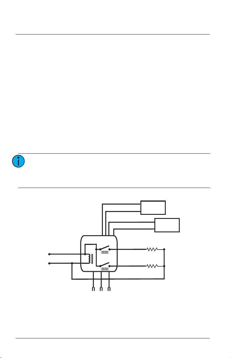
DMX-512A
Black
Line In
White
Neutral
Load 1
Red
Load 2
Red/White
Dimming
Ballast 1
Dimming
Ballast 2
Gray
0–10V
Violet
Gray/White
0–10V
Violet/White
0–10V Controller
Connect Power Input and Relay Output
The power input and relay output wiring exits the 0–10V Controller through
the knockout mount on the enclosure.
1: Connect the power input wiring.
a: Connect the white wire (14 AWG) to the incoming neutral wire
from the breaker panel and the neutral wire of the lighting load.
b: Connect the power input wire (12 AWG) to the line input feed
wire (hot) from the breaker panel. Power input wire is black for
120VAC or brown for 277VAC.
2: Connect the relay output wiring. The 0–10V Controller has two relay
output wires (18 AWG): Zone 1 is red and Zone 2 is red/white.
a: Connect the Zone 1 relay output wire (red) to the hot input of the
first load.
b: Connect the Zone 2 relay output wire (red/white) to the hot input
of the second load.
Note:
When configured to single-channel mode, a single DMX
address controls both relays. If you are using only one
output, cap off the unused wires with wire nuts (not
included).
0–10V Controller Page 6 of 16 ETC
Page 7
ETC Installation Guide
0–10V Controller
Connect 0–10V Dimming Output
WARNING:
The 0–10V dimming output wiring exits the 0–10V Controller through the
top nipple of the enclosure with the power wiring.
1: Connect the 0–10V dimming output wiring. The 0–10V Controller has
two pairs of 0–10V output wires (22 AWG): Zone 1 is gray and violet,
and Zone 2 is gray/white and violet/white.
a: Connect the Zone 1 output wires, gray (+) and violet (-), to the
b: Connect the Zone 2 output wires, gray/white (+) and
2: Reinstall the junction box cover plate.
CAUTION:
RISK OF DEATH OR INJURY BY ELECTRIC SHOCK!
0–10V wiring may not be fully isolated from high
voltage AC power. Do not assume that 0–10V wiring is
safe to touch, even when run as an NEC Class 2 signal.
Test for AC voltage to ground before terminating any
0–10V control wiring to the 0–10V Controller.
control input of the connected load.
violet/white (-), to the control input of the second connected load.
The 0–10V control outputs must be treated as
NEC Class 1 control signals, in the same manner as other
high voltage connections.
0–10V Controller Page 7 of 16 ETC
Page 8

ETC Installation Guide
0–10V Controller
Configure the 0–10V Controller
You can use RDM to set the DMX address and data loss behavior for the
0–10V Controller. You can set other parameters using RDM, too. See
Parameters
Channel Mode
You can configure the 0–10V Controller to single-channel or dual-channel
mode using Net3 Concert or another RDM controller. In dual-channel mode,
each relay is assigned a separate DMX address for control. In single-channel
mode, both relays are assigned to a single DMX address and function in
unison. The 0–10V Controller ships from the factory in dual-channel mode.
See
You can also switch between single-channel mode and dual-channel mode
using the SET button on the 0–10V Controller. Press and hold the SET button
to switch modes. The POWER LED will blink once for single-channel mode or
twice for dual-channel mode.
DMX Address
You can assign DMX addresses to an entire daisy chain of Unison Foundry
devices using Net3 Concert or another RDM controller. If you cannot assign
the DMX addresses using RDM, you can manually set the DMX start address
on the device. The default factory-set DMX address is 1, and the range of
available addresses is 1–512.
on
page 14
RDM Parameters
.
on
page 14
.
RDM
0–10V Controller Page 8 of 16 ETC
Page 9

ETC Installation Guide
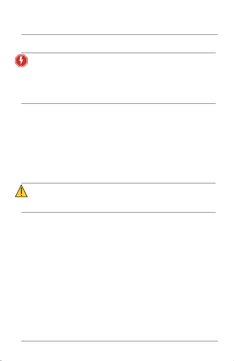
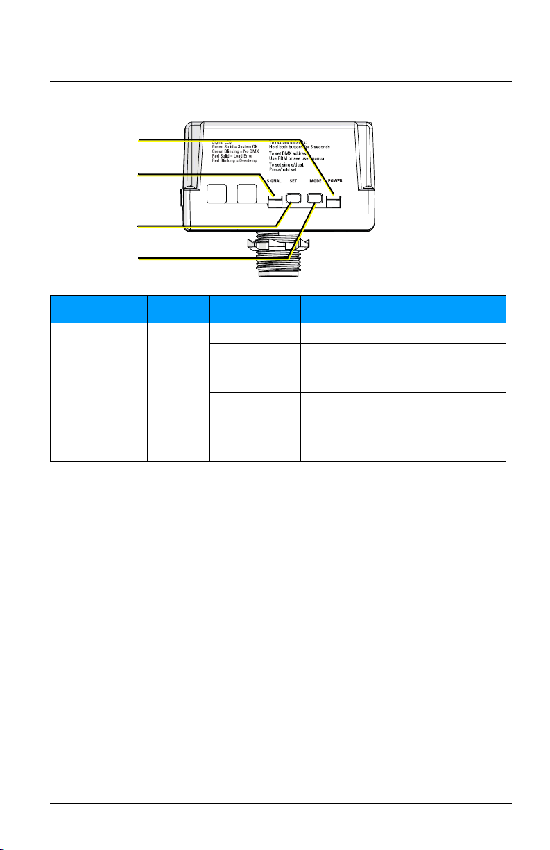
SIGNAL LED
POWER LED
MODE button
SET button
201
10s 1s100s
0–10V Controller
Manually Set the DMX Address
If you cannot assign the DMX addresses using RDM, use the MODE and SET
buttons to set the value of each digit in the three-digit DMX address in
sequence.
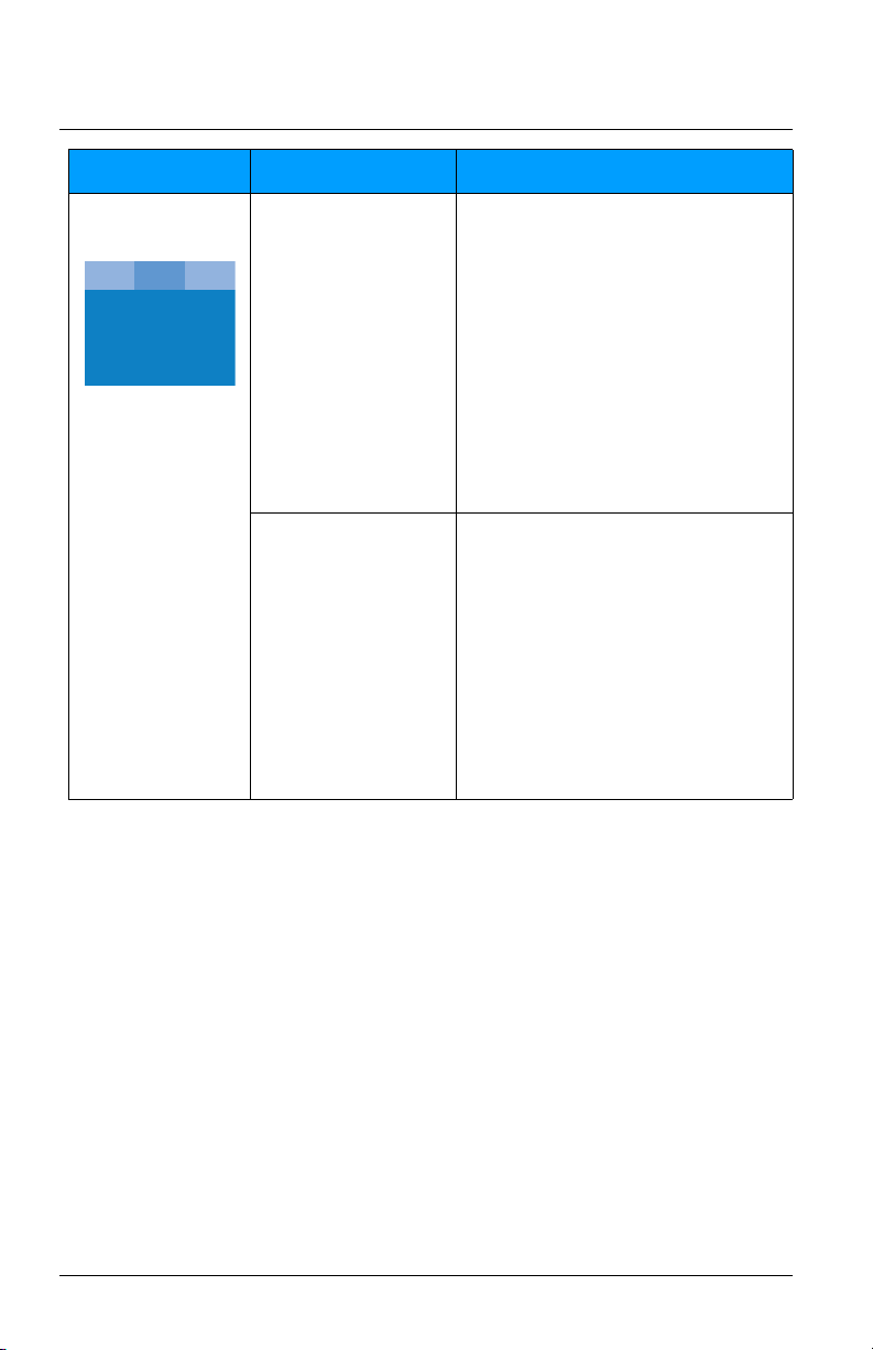
Task What to do What you will see
1: Put the controller
into DMX addressing
mode.
2: Set the 100s digit
of the DMX address.
0–10V Controller Page 9 of 16 ETC
Press and hold the MODE
button.
Press the SET button to
set the 100s digit. For
example, press the button
once for 1, twice for 2,
and so forth up to five
times for 5. Press and hold
the SET button for 0.
If the 100s digit in the
new DMX address is the
same as in the current
DMX address, you can
keep the digit by skipping
to step 3.
•The POWER LED indicator blinks 3 times
to indicate that you can set the 100s
digit of the DMX address.
•The SIGNAL LED indicator blinks the
100s digit in the current DMX address.
For example, if the current DMX address
is 201, the SIGNAL LED indicator blinks
2 times. (If the 100s digit is a 0, the
indicator remains lit and does not blink.)
•The POWER LED indicator continues to
blink 3 times to indicate that you are
setting the 100s digit of the DMX
address.
•The SIGNAL LED indicator blinks the
value that you set for the 100s digit in
the DMX address.
Page 10
ETC Installation Guide
201
10s 1s100s
0–10V Controller
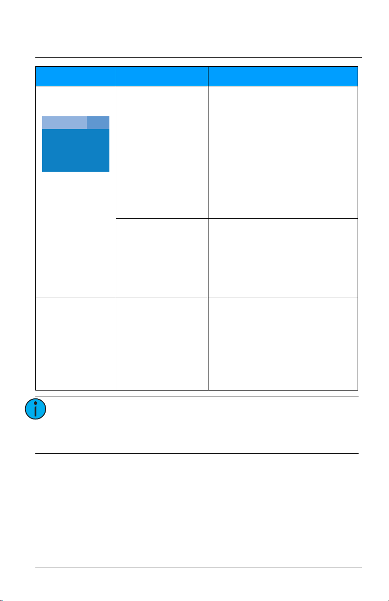
Task What to do What you will see
3: Set the 10s digit of
the DMX address.
Press the MODE button to
advance to the 10s digit.
Press the SET button to
set the 10s digit. For
example, press the button
once for 1, twice for 2,
and so forth up to nine
times for 9. Press and hold
the SET button for 0.
If the 10s digit in the new
DMX address is the same
as in the current DMX
address, you can keep the
digit by skipping to step 4.
•The POWER LED indicator blinks 2 times
to indicate that you are setting the 10s
digit of the DMX address.
•The SIGNAL LED indicator blinks the 10s
digit in the current DMX address. For
example, if the current DMX address is
201, the SIGNAL LED indicator remains
lit and does not blink.
• If the SIGNAL LED indicator rapidly blinks
red, this means that you set the 100s
digit to an invalid value (for example, 6).
When this occurs, the 0–10V Controller
exits DMX addressing mode without
saving.
•The POWER LED indicator continues to
blink 2 times to indicate that you are
setting the 10s digit of the DMX address.
•The SIGNAL LED indicator blinks the
value that you set for the 10s digit in the
DMX address.
0–10V Controller Page 10 of 16 ETC
Page 11
ETC Installation Guide
10s
201
1s100s
0–10V Controller
Task What to do What you will see
4: Set the 1s digit of
the DMX address.
5: Save the new DMX
address.
Press the MODE button to
advance to the 1s digit.
Press the SET button to
set the 1s digit.
If the 1s digit in the new
DMX address is the same
as in the current DMX
address, you can keep the
digit by skipping to step 5.
Press the MODE button. • The POWER LED indicator and SIGNAL
•The POWER LED indicator blinks once to
indicate that you are setting the 1s digit
of the DMX address.
•The SIGNAL LED indicator blinks the 1s
digit in the current DMX address. For
example, if the current DMX address is
201, the SIGNAL LED indicator blinks
once.
• If the SIGNAL LED indicator rapidly blinks
red, this means that you set the 10s digit
to an invalid value. When this occurs, the
0–10V Controller exits DMX addressing
mode without saving.
•The POWER LED indicator continues to
blink once to indicate that you are
setting the 1s digit of the DMX address.
•The SIGNAL LED indicator blinks the
value that you set for the 1s digit in the
DMX address.
LED indicator return to their normal
functions (see
Interface
• If the SIGNAL LED indicator rapidly blinks
red, this means that you set the 1s digit
to an invalid value. When this occurs, the
0–10V Controller exits DMX addressing
mode without saving.
LED Indicators and User
on
page 13
).
0–10V Controller Page 11 of 16 ETC
Note:
The 0–10V Controller will exit DMX addressing mode
after 1 minute of inactivity. When this occurs, the
controller retains the DMX address that was saved
before you entered DMX addressing mode.
Page 12

ETC Installation Guide
0–10V Controller
Data Loss Behavior
Use RDM to set the behavior of the 0–10V Controller when DMX is lost. The
0–10V Controller has three options for data loss behavior:
• Hold last look
• Wait and fade
• Go to full
Note:
The “Go to full” data loss behavior does not meet the
requirements of UL924 for emergency lighting control.
Power Up and Test
1: Restore power to the circuit. The 0–10V Controller will power up and
turn on all connected loads to full output.
2: Verify that DMX input is present. The green signal LED on the unit
should be lit steadily. If it is blinking, check the DMX wiring.
3: Configure the controller. If additional configuration is required, use an
RDM controller such as ETC Net3 Concert software to configure the
appropriate properties. For more detailed information, see the Net3
Concert integrated help system.
4: Test the controller response. Use the DMX control system to alter the
control level, and make sure the 0–10V Controller responds.
Power-Up Behavior
In the event of a power loss to the 0–10V Controller, the controller will return
to its last output level when power is restored.
0–10V Controller Page 12 of 16 ETC
Page 13
ETC Installation Guide
SIGNAL LED
POWER LED
MODE button
SET button
0–10V Controller
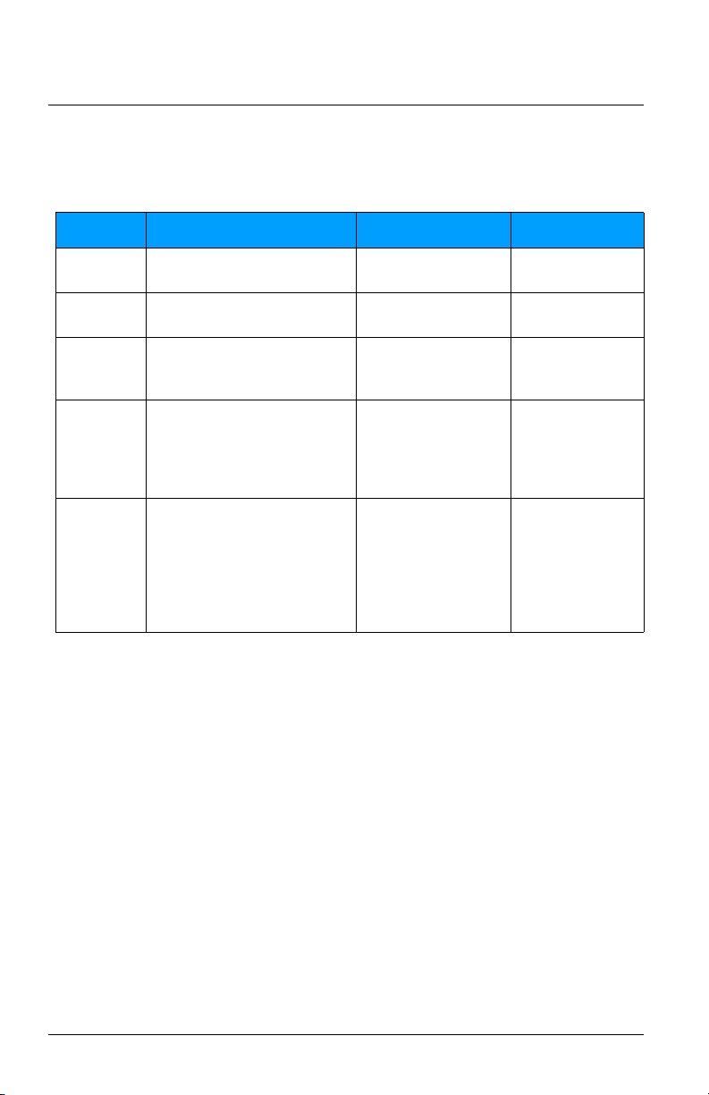
LED Indicators and User Interface
LED Indicator Color State Description
Solid DMX present, system OK.
DMX absent. Verify that the DMX wiring is
SIGNAL Green
Slow blinking
Rapid blinking
POWER Blue Solid Power is OK.
correct, and verify that the DMX source is
functioning correctly.
DMX errors. Verify that the DMX wiring is
correct, and verify that the DMX source is
functioning correctly.
Update the Software
You can update the software for the 0–10V Controller using ETC
UpdaterAtor software and an ETC Gadget II or Gateway. Both LED indicators
on the 0–10V Controller blink during software updates.
Restore Defaults
Return the 0–10V Controller to factory defaults by pressing and holding both
the MODE and SET buttons simultaneously for 5 seconds. Both LEDs will blink
rapidly to indicate that the factory defaults have been restored. For factory
default values, see
0–10V Controller Page 13 of 16 ETC
RDM Parameters
on
page 14
.
Page 14
ETC Installation Guide
0–10V Controller
RDM Parameters
You can set the following RDM parameters on the 0–10V Controller using
Net3 Concert or another RDM controller.
Parameter ID and Number Description Default Value
Device Label
DMX Start
Address
DMX
Personality
DMX Fail
Mode
(Data Loss)
Packet Delay
E120_DEVICE_LABEL
0x0082
E120_DMX_START_ADDRESS
0x00F0
E120_DMX_PERSONALITY
0x00E0
E137_1_DMX_FAIL_MODE
0x0141
ETC_E120_PACKET_DELAY
0xB000
User-configurable name
for the device
DMX address,
range = 1–512
Sets the channel mode:
• Dual-channel mode
• Single-channel mode
Configures the behavior
when DMX is lost:
• Hold last look
• Wait and fade
• Go to full
Requires any change of
level to be present for at
least this number of
packets before action is
taken (open/close the
relay or change 0–10V
output). Range = 0–50.
ETC DMX Dual Relay
0–10V
1
Dual-channel mode
Go to full
0
0–10V Controller Page 14 of 16 ETC
Page 15

ETC Installation Guide
0–10V Controller
0–10V Controller Page 15 of 16 ETC
Page 16

ETC Installation Guide
0–10V Controller
0–10V Controller Page 16 of 16 ETC
 Loading...