

Page 1
ETC Setup Guide
Option
module
Ethernet patch
panel
Ethernet switch
panel
Step 1:
Step 2:
ERn Ethernet Switch Module Installation
The ERn Ethernet Switch module installs in the bottom option module tray of the ERn enclosure, replacing
the blank module that ships in the ERn from the factory. The bottom option slot is the only position for the
Ethernet switch module.
Note:
The Ethernet switch module (ERn-NET) is not designed for use in a rack mounted ERn
unit. Instead, utilize a rack mounted Ethernet switch (provided by others).
Additionally, the ERn-NET is not supported in an ERn4 enclosure at 230 VAC.
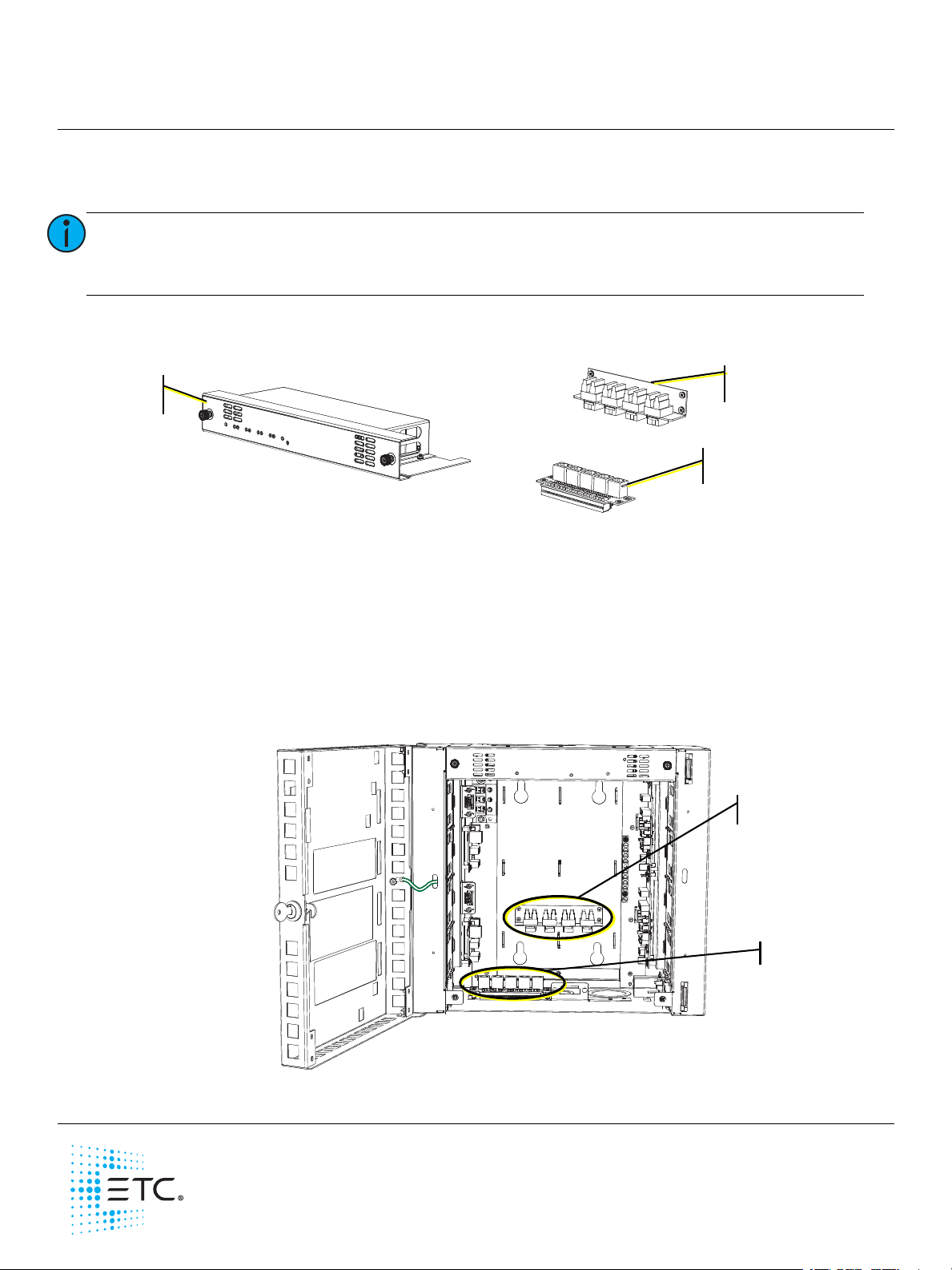
The ERn Ethernet switch (ERn-NET) provides four ports of Power over Ethernet (PoE). The ERn Ethernet
switch kit includes an option module, Ethernet patch panel, Ethernet switch panel, and B Ethernet patch
cables.
The Ethernet patch panel includes four punch down terminal blocks that accept CAT5e wire. Building wire
enters the ERn enclosure and terminates to this patch panel. For each Ethernet data run, an Ethernet patch
cable is provided to connect between the Ethernet patch panel and the Ethernet switch panel.
Install the Ethernet Switch Option
1: Install the Ethernet patch panel to the mounting studs on the rear panel of the ERn enclosure using
the hardware provided.
2: Install the Ethernet switch panel to the mounting studs on the bottom panel of the ERn enclosure
using the hardware provided. Be sure to install the panel with the card edge receptacle facing the
front of the ERn enclosure.
Corporate Headquarters Middleton, WI, USA Tel +608 831 4116 Service: (Americas) service@etcconnect.com
London, UK
Rome, IT
Holzkirchen, DE
Hong Kong
Web: etcconnect.com
Product information and specifications subject to change. ETC intends this document to be provided in its entirety.
7180M2230
Tel +44 (0)20 8896 1000 Service: (UK) service@etceurope.com
Tel +39 (06) 32 111 683 Service: (UK) service@etceurope.com
Tel +49 (80 24) 47 00-0 Service: (DE) techserv-hoki@etcconnect.com
Tel +852 2799 1220 Service: (Asia) service@etcasia.com
© 2016 Electronic Theatre Controls, Inc.
Rev B Released 11/2016
Page 2
ETC Setup Guide
Press here gently with
screwdriver to release
connector from panel.
ERn Ethernet Switch Module
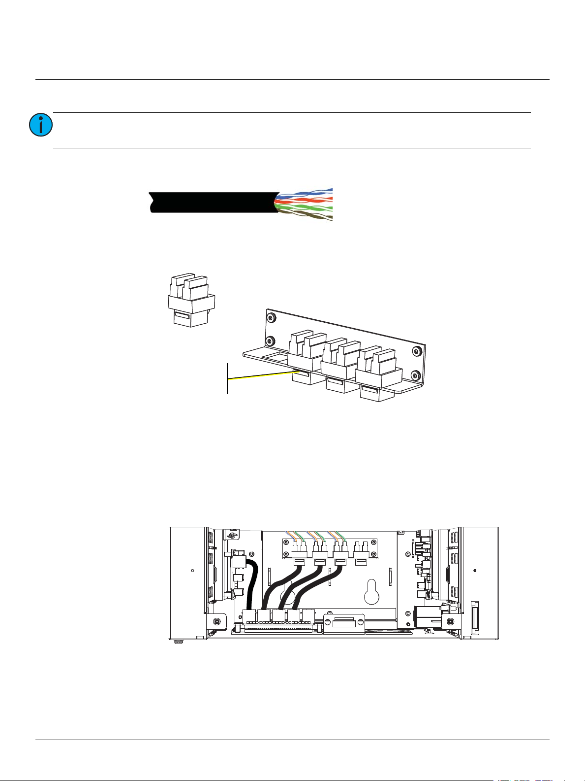
Connect CAT5e Wiring
Note:
1: Pull your CAT5e building wire through the conduit access previously prepared.
2: Use a slotted screwdriver to remove the Ethernet punch down connector from the Ethernet patch
panel and remove the connector covers from each side to reveal the connector terminals. The punch
down connector provides insulation displacement therefore stripping of wire is not required.
All Ethernet terminations must follow IEEE 802.3 and be terminated to the T568B
standard.
3: Reference the connector label for the CAT5e wire termination color code.
4: Use a 110 punch down tool (not provided) to complete the wire termination and replace the
protective covers over the wire terminals.
5: Replace the punch down connector in the patch panel.
6: Connect Ethernet patch cables.
a: Connect a patch cable from the left I/O to the first RJ-45 input on the Ethernet switch panel.
b: Connect a patch cable from the punch down connector to an RJ-45 input on the switch panel.
Repeat for each building service connection (up to four).
ERn Ethernet Switch Module Page 2 of 3 ETC
Page 3

ETC Setup Guide
PoE
Power
LINK/ACT
1
234
5
ERn Ethernet Switch Module
7: Install the Ethernet switch option module into the enclosure and secure it in place using the captured
screws provided.
Status Indicators
When power is applied to the ERn, the Paradigm Ethernet option module LEDs, located on the front panel,
indicate main power, data, and PoE power status.
• The power LED is blue and will illuminate when the Ethernet switch is powered.
• The LINK/ACT and PoE power LEDs are typical of an Ethernet switch.
- The Link/Act indicator is green and is on if there is a device connected to that port. A blinking LED
indicates data activity on the port.
- The PoE indicator is yellow and will be on if the Ethernet switch is supplying power to the device
connected to that port. A blinking PoE LED indicates a powering error on that port.
Note:
Port one does not have a PoE power indicator as it does not supply power. Port one is
always connected to the Paradigm architectural control processor which is powered by
the ERn rack power supply.
ERn Ethernet Switch Module Page 3 of 3 ETC
 Loading...