

Page 1
ETC Installation Guide
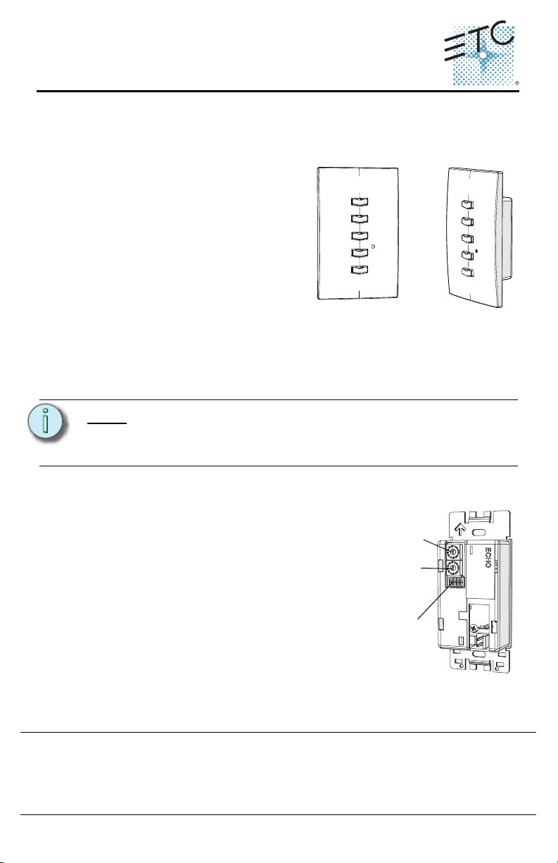
Address wheel
Space wheel
DIP switches
Echo Preset Station Installation
Overview
Echo preset stations are used to activate built-in presets in compatible power
control products.
Stations mount using a standard singlegang back box (RACO 690 or equivalent),
or an optional surface mount backbox
(ETC part number 7081A2004-1). Station
faceplates and buttons are available in
cream, ivory, grey, black and signal white.
Preset stations are provided with station
electronics, buttons, faceplate, a
termination kit, and installation hardware.
Installation Requirements
Preset station wiring uses (1) Belden 8471 and (1) 2.5mm2 (14 AWG) ESD ground
wire. Wiring is topology-free and may be bus, star, loop, home run or any
combination of these. Data wiring is limited to a total of 1640 feet (500 meters)
NEC Class 2 product to be wired in accordance to NEC Article 725 and local
jurisdiction requirements.
.
Note:
ETC requires that all stations be grounded by using grounded metal
conduit or a 14 AWG ESD drain wire. All control wiring should be
installed and terminated by a qualified installer and should follow
standard wiring installation practices.
Setting Station Functionality
Before installing, you must first assign an
address to the station and, if desired, adjust the
station’s functionality. Address is set using the
two numbered wheels on the rear of the station.
Functionality is set using the DIP switches found
just below the numbered wheels. The label on the
rear of the station identifies these components
and functions.
Setting the Address and Space
Station address is defined by the two numbered
wheels found on the back of the station. The top
address wheel defines the station address (1-16).
Corporate Headquarters
London, UK
Unit 26-28, Victoria Industrial Estate, Victoria Road, London W3 6UU, UK Tel +44 (0)20 8896 1000 Fax +44 (0)20 8896 2000
Rome, IT
Via Pieve Torina, 48, 00156 Rome, Italy Tel +39 (06) 32 111 683 Fax +44 (0)20 8752 8486
Holzkirchen, DE
Hong Kong Rm 1801, 18/F, Tower 1 Phase 1, Enterprise Square, 9 Sheung Yuet Road, Kowloon Bay, Kowloon, Hong Kong Tel +852 2799 1220
Service:
(Americas) service@etcconnect.com
Web:
www.etcconnect.com
7140M2110 Rev A Released 2013-03 ETC intends this document to be provided in its entirety.
Echo Preset Station Page 1 of 6 ETC, Inc.
3031 Pleasant View Road, P.O. Box 620979, Middleton, Wisconsin 53562-0979 USA Tel +608 831 4116 Fax +608 836 1736
Ohmstrasse 3, 83607 Holzkirchen, Germany Tel +49 (80 24) 47 00-0 Fax +49 (80 24) 47 00-3 00
Copyright © 2013 ETC. All Rights Reserved. Product information and specifications subject to change.
(UK) service@etceurope.com (DE) techserv-hoki@etcconnect.com
(Asia) service@etcasia.com
Page 2
ETC Installation Guide
Echo Preset Station Installation
The bottom wheel defines the space which the station will control (also 1-16).
CAUTION:
Step 1: Set the space wheel to the appropriate number (1 thru 16) for the
Step 2: Set the address wheel to a unique number (1 thru 16) for the space.
Note:
Each station must have its station address set to a unique number (1-
16) for the space it controls. If two or more stations use the same
address for the same space, the system will not function properly.
space you want the station to control.
Total number of preset stations is limited by the power supply at the
host product. Refer to the host product documentation for the limits
specific to your system.
Setting Station Functionality
The bank of DIP switches found on the rear of the station can be set to alter
station functionality. Using a micro-tool you can slide the DIP switches up (On) to
activate them or down (Off) to deactivate. They are set to “OFF” by default.
The DIP switches have the following designations:
• DIP switch 1: “Use Off” - When set to on (up), the last button on the station
is set as an “OFF” command for the space. When set to off (down) the
button will activate a preset.
• DIP switch 2: “Custom Config” - for future development.
• DIP switch 3: “Disable IR Input” - When on (up), the infrared input for this
station will be disabled.
• DIP switch 8: “Restore Defaults”- When on (up), a “restore defaults at boot”
function is activated. Factory defaults can then be restored by:
a: disconnecting power from the station, then
b: reconnecting power to the station, then
c: resetting the DIP switch to down. This will prevent losing the
configuration in the event of a power loss.
All other DIP switches are unused.
Installing the Preset Station
Install Back Box
Step 1: Mount the back box using appropriate hardware for the surface you
are mounting to.
Step 2: Run conduit and wiring as required by the installation drawings.
Step 3: Leave a service loop of approximately 10” (254mm) of wiring in the
backbox.
Echo Preset Station Page 2 of 6 ETC, Inc.
Page 3
ETC Installation Guide
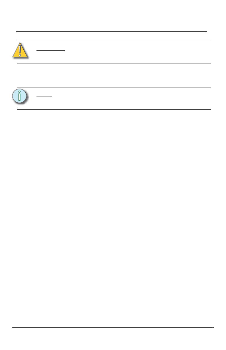
Topology of a single
station installation
Topology of multiple
stations installed in
series
Installed control wire
Pigtail wire
Installed control wire
Installed wire to next station
Pigtail wire
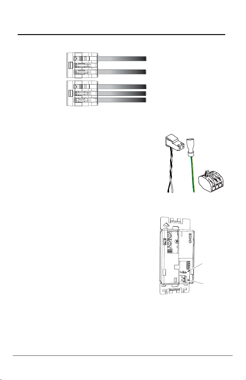
Station power
pigtail
Ground
pigtail
WAGO
Ground
spade
Data
connector
Echo Preset Station Installation
Connect the Wiring
Step 4: Terminate and connect the station wiring.
a: Locate the data pigtail and two WAGO LeverLock connectors
found in the termination kit.
b: Strip 3/8” (9-10mm) from the
ends of each wire (both pigtail
and installed data wire).
c: Open the terminal levers on
the WAGO connector and
insert the Belden 8471 black
(-) lead wire and the black (-)
lead from the pigtail into the
terminals.
d: Close the levers onto the
wires, securing the
connection between the two.
e: Repeat this process for the Belden 8471 white (+) wire and
remaining white (+) pigtail wire using another WAGO connector.
f: Attach the connector onto the
preset station data connector.
Step 5: Terminate the ESD drain (ground)
wire.
a: Locate the ground pigtail and one
WAGO LeverLock connector from
the termination kit.
b: Strip 3/8” (9-10mm) from the end
of the ground wire and ground
pigtail.
c: Open the terminal levers on the
connector and insert the installed
(typically green/yellow) ESD drain
(ground) wire and the green/yellow lead from the pigtail into the
Echo Preset Station Page 3 of 6 ETC, Inc.
terminals.
d: Close the levers onto the wires, securing the connection between
the two.
Page 4

ETC Installation Guide
1
3
2
4
Echo Preset Station Installation
e: Attach the ground spade onto the preset station ground spade
(indicated above).
Note:
A ground connection (14 AWG) is required for any station not
installed with grounded metal conduit.
Installing the Station in the Backbox
Spacers are provided to help position the station and cover flush with the wall in
flush mount applications. The spacers are not used with surface mount
backboxes.
Step 1: Insert the station electronics and wiring into the backbox. The
arrow on the mounting plate must point up.
Note:
For some flush mount applications with certain trim rings it may be
necessary to remove the station’s back cover for insertion into the
backbox.
Step 2: If needed, fold sections of the spacer over each other and press
them together to achieve the required thickness to fill the gap
between the station and backbox. Cut off any excess spacers and
place the spacer between the station and backbox.
Step 3: Secure the station with two screws. If using spacers, make sure the
screws pass through them.
CAUTION:
Overtightening of the mounting screws may result in poor button
activation.
Step 4: Install the button caps (included with the faceplate kit) so that the
clear light tunnels protrude through the caps.
Echo Preset Station Page 4 of 6 ETC, Inc.
Page 5

ETC Installation Guide
Echo Preset Station Installation
Installing the Faceplate
The faceplate is secured to the station with two magnets that are located on the
bottom edge of the faceplate.
Step 1: Align the top of the faceplate approximately 20 degrees to the
station.
Step 2: Hook the top of the faceplate on the tabs located on the top of the
station electronics assembly. To ensure the faceplate is hooked
properly on the top hook, wiggle it slightly side to side while the
bottom is angled about 20 degrees from the wall.
Step 3: Swing the bottom of the faceplate down until the magnets engage.
Step 4: If the faceplate does not fully attach, wiggle the bottom of the plate
until the magnets are seated properly to the station and the
faceplate is secure.
Custom Settings
You can change the presets associated with the station as well as change the
color of all the LEDs on any given station.
Assigning Presets
Stations default to controlling presets 1-5. Any station can be set to control any
consecutively numbered block of presets. For example: a 5-button station can
control presets 1-5, 3-7, 14-18, and so on.
Echo Preset Station Page 5 of 6 ETC, Inc.
Page 6

ETC Installation Guide
MODE Button on
5-button station
MODE Button on
10-button station
Echo Preset Station Installation
Power must be connected to the station to assign the presets. To set the
consecutively numbered presets for any station:
Step 1: Press and hold the “MODE”
button for three seconds.
“MODE” is found on the front of
the station electronics near the
middle preset button.The LED
beneath the MODE button will
illuminate.
Step 2: Press the first preset button on
the station a number of times
equal to the first preset you want
the station to control. For
example: press it 6 times to
associate the station with
presets 6-10 on a 5-button
station (6-15 on a 10-button
station). The first preset button
will flash to indicate the first preset number. The number of flashes
equals the station’s starting preset number.
a: After 90 seconds of inactivity, the “MODE” status will time out and
any changes will be aborted.
b: Button presses are cumulative. If you need to increase the
desired number, press the first preset button additional times.
c: If you have added too many, wait for the 90 second time-out to
abort the changes and then repeat this procedure.
Step 3: Once you have added the desired number of presses, press and
release the “MODE” button. The first preset button will now match
the number of presses, with subsequent presets increasing by one.
Changing LED color
Stations default to illuminating preset buttons in green. To change the color of
the LEDs for any station:
Step 1: Press and hold the “MODE” button for five seconds. “MODE” is
found on the front of the station electronics near the middle preset
button.The LED beneath the MODE button will illuminate and all of
Step 2: Press the first preset button to cycle through the available colors
Step 3: Press and release the “Mode” button. The selected color of the
Service
If you have any difficulties installing your system or with system startup please
contact ETC Technical Services at the office nearest you. ETC contact
information is located at the bottom of page 1.
Echo Preset Station Page 6 of 6 ETC, Inc.
the preset buttons will display in their current color.
until you find the desired one. After 90 seconds of inactivity, the
“MODE” status will time out and any changes will be aborted.
preset buttons for that station will display.
Page 7

Page 8

 Loading...