

Page 1

Lighting Control System
™
Operations Manual
Copyright © 2007 Electronic Theatre Controls, Inc.
All Rights reserved.
Product information and specifications subject to change.
Part Number: 4250M1210-1.3.0 Rev A
Released: December 2007
Page 2

ETC®, Eos™, Emphasis®, Expression®, Insight™, Imagine™, Focus™, Express™, Unison®,
Obsession
®
II, ETCNet2™, EDMX™, Revolution® and Sensor+®, are either registered
trademarks or trademarks of Electronic Theatre Controls, Inc. in the United States and other
countries.
Page 3

Table of Contents
Introduction . . . . . . . . . . . . . . . . . . . . . . . . . . 1
Using this Manual. . . . . . . . . . . . . . . . . . . . . . . . . . . . . . . . . . . . . . . .2
Register Your Eos . . . . . . . . . . . . . . . . . . . . . . . . . . . . . . . . . . . . . . .3
Help from ETC Technical Services . . . . . . . . . . . . . . . . . . . . . . . . . .3
Important Concepts . . . . . . . . . . . . . . . . . . . . . . . . . . . . . . . . . . . . . .4
Channel . . . . . . . . . . . . . . . . . . . . . . . . . . . . . . . . . . . . . . . . . . . .4
Syntax Structure . . . . . . . . . . . . . . . . . . . . . . . . . . . . . . . . . . . . .4
Parameters and Parameter Categories. . . . . . . . . . . . . . . . . . . .5
Tracking vs. Cue Only . . . . . . . . . . . . . . . . . . . . . . . . . . . . . . . . .5
Move Instruction . . . . . . . . . . . . . . . . . . . . . . . . . . . . . . . . . . . . .5
Move Fade. . . . . . . . . . . . . . . . . . . . . . . . . . . . . . . . . . . . . . . . . .6
HTP vs. LTP . . . . . . . . . . . . . . . . . . . . . . . . . . . . . . . . . . . . . . . .7
Other Reference Materials . . . . . . . . . . . . . . . . . . . . . . . . . . . . . . . . .8
Help System . . . . . . . . . . . . . . . . . . . . . . . . . . . . . . . . . . . . . . . .8
Chapter 1
Chapter 2
System Overview . . . . . . . . . . . . . . . . . . . . . 9
System Components . . . . . . . . . . . . . . . . . . . . . . . . . . . . . . . . . . . .10
Console . . . . . . . . . . . . . . . . . . . . . . . . . . . . . . . . . . . . . . . . . . .10
Button Modules . . . . . . . . . . . . . . . . . . . . . . . . . . . . . . . . . . . . .11
Remote Processor Unit (RPU). . . . . . . . . . . . . . . . . . . . . . . . . .11
Remote Video Interface (RVI) . . . . . . . . . . . . . . . . . . . . . . . . . .11
Radio Focus Remote (RFR) . . . . . . . . . . . . . . . . . . . . . . . . . . .11
Gateways. . . . . . . . . . . . . . . . . . . . . . . . . . . . . . . . . . . . . . . . . .12
Console Geography . . . . . . . . . . . . . . . . . . . . . . . . . . . . . . . . . . . . .13
Terminology . . . . . . . . . . . . . . . . . . . . . . . . . . . . . . . . . . . . . . . .13
Littlites
Cleaning Eos . . . . . . . . . . . . . . . . . . . . . . . . . . . . . . . . . . . . . . .15
Console Capacities . . . . . . . . . . . . . . . . . . . . . . . . . . . . . . . . . . . . .16
Output Parameters . . . . . . . . . . . . . . . . . . . . . . . . . . . . . . . . . .16
Channel Counts . . . . . . . . . . . . . . . . . . . . . . . . . . . . . . . . . . . . .16
Cues and Cue Lists . . . . . . . . . . . . . . . . . . . . . . . . . . . . . . . . . .16
Record Targets . . . . . . . . . . . . . . . . . . . . . . . . . . . . . . . . . . . . .16
Faders . . . . . . . . . . . . . . . . . . . . . . . . . . . . . . . . . . . . . . . . . . . .16
Outputting DMX . . . . . . . . . . . . . . . . . . . . . . . . . . . . . . . . . . . . . . . .17
® . . . . . . . . . . . . . . . . . . . . . . . . . . . . . . . . . . . . . . . . . . . . . . . . . . . . . 15
System Installation . . . . . . . . . . . . . . . . . . .19
Basic System Risers . . . . . . . . . . . . . . . . . . . . . . . . . . . . . . . . . . . .20
Large System Riser . . . . . . . . . . . . . . . . . . . . . . . . . . . . . . . . . . . . .21
Table of Contents i
Page 4

Chapter 3
System Basics . . . . . . . . . . . . . . . . . . . . . . 23
Power . . . . . . . . . . . . . . . . . . . . . . . . . . . . . . . . . . . . . . . . . . . . . . . .24
Power up the console . . . . . . . . . . . . . . . . . . . . . . . . . . . . . . . .24
Power down the console . . . . . . . . . . . . . . . . . . . . . . . . . . . . . .24
The Central Information Area (CIA) . . . . . . . . . . . . . . . . . . . . . . . . .25
The Command Line . . . . . . . . . . . . . . . . . . . . . . . . . . . . . . . . . .25
Parameter Display . . . . . . . . . . . . . . . . . . . . . . . . . . . . . . . . . . .26
Browser . . . . . . . . . . . . . . . . . . . . . . . . . . . . . . . . . . . . . . . . . . .26
Collapse/Expand the CIA. . . . . . . . . . . . . . . . . . . . . . . . . . . . . .26
Using the Browser . . . . . . . . . . . . . . . . . . . . . . . . . . . . . . . . . . . . . .27
Virtual Keypad . . . . . . . . . . . . . . . . . . . . . . . . . . . . . . . . . . . . . .27
Setting Up the Touchscreens . . . . . . . . . . . . . . . . . . . . . . . . . . . . . .28
Clearing the Touchscreens . . . . . . . . . . . . . . . . . . . . . . . . . . . .28
Populating the Touchscreens . . . . . . . . . . . . . . . . . . . . . . . . . .28
Organizing the Direct Selects . . . . . . . . . . . . . . . . . . . . . . . . . .29
Using Direct Selects . . . . . . . . . . . . . . . . . . . . . . . . . . . . . . . . .30
Display Control and Navigation . . . . . . . . . . . . . . . . . . . . . . . . . . . .32
Opening and Closing Displays. . . . . . . . . . . . . . . . . . . . . . . . . .32
Selecting Displays . . . . . . . . . . . . . . . . . . . . . . . . . . . . . . . . . . .33
Moving Displays. . . . . . . . . . . . . . . . . . . . . . . . . . . . . . . . . . . . .33
Scrolling within a Display . . . . . . . . . . . . . . . . . . . . . . . . . . . . . .33
Expanding Displays . . . . . . . . . . . . . . . . . . . . . . . . . . . . . . . . . .33
Graphical User Interface (GUI) Display Conventions. . . . . . . . . . . .34
Indicators in the live/blind display . . . . . . . . . . . . . . . . . . . . . . .34
[Data] Key . . . . . . . . . . . . . . . . . . . . . . . . . . . . . . . . . . . . . . . . .37
[Time] Key . . . . . . . . . . . . . . . . . . . . . . . . . . . . . . . . . . . . . . . . .37
Using Flexichannel . . . . . . . . . . . . . . . . . . . . . . . . . . . . . . . . . .37
Indicators in the playback status display . . . . . . . . . . . . . . . . . .38
Using [Format] . . . . . . . . . . . . . . . . . . . . . . . . . . . . . . . . . . . . . . . . .40
Timeline Format. . . . . . . . . . . . . . . . . . . . . . . . . . . . . . . . . . . . .45
Encoders . . . . . . . . . . . . . . . . . . . . . . . . . . . . . . . . . . . . . . . . . . . . .47
Encoder Navigation . . . . . . . . . . . . . . . . . . . . . . . . . . . . . . . . . .47
Encoder Touchscreen . . . . . . . . . . . . . . . . . . . . . . . . . . . . . . . .47
Using Softkeys . . . . . . . . . . . . . . . . . . . . . . . . . . . . . . . . . . . . . . . . .48
Context Sensitive Softkeys . . . . . . . . . . . . . . . . . . . . . . . . . . . .48
Changing Softkey Pages . . . . . . . . . . . . . . . . . . . . . . . . . . . . . .48
. . . . . . . . . . . . . . . . . . . . . . . . . . . . . . . . . . . . . . . . . . . . . . . . . .48
ii Eos Operations Manual
Page 5

Chapter 4
Managing Show Files . . . . . . . . . . . . . . . . . 49
Create a New Show File. . . . . . . . . . . . . . . . . . . . . . . . . . . . . . . . . .50
Open an Existing Show File . . . . . . . . . . . . . . . . . . . . . . . . . . . . . . .51
Saving an Existing Show File . . . . . . . . . . . . . . . . . . . . . . . . . . . . . .53
Using Save As . . . . . . . . . . . . . . . . . . . . . . . . . . . . . . . . . . . . . . . . .54
Importing Show Files . . . . . . . . . . . . . . . . . . . . . . . . . . . . . . . . . . . .55
Exporting a Show File . . . . . . . . . . . . . . . . . . . . . . . . . . . . . . . . . . .56
Deleting a File . . . . . . . . . . . . . . . . . . . . . . . . . . . . . . . . . . . . . . . . .57
Chapter 5
Patch. . . . . . . . . . . . . . . . . . . . . . . . . . . . . .59
About Patch . . . . . . . . . . . . . . . . . . . . . . . . . . . . . . . . . . . . . . . . . . .60
Displays . . . . . . . . . . . . . . . . . . . . . . . . . . . . . . . . . . . . . . . . . . . . . .61
Channel View. . . . . . . . . . . . . . . . . . . . . . . . . . . . . . . . . . . . . . .61
Address View. . . . . . . . . . . . . . . . . . . . . . . . . . . . . . . . . . . . . . .61
Changing the Patch View . . . . . . . . . . . . . . . . . . . . . . . . . . . . . . . . .62
Create and Edit Patch . . . . . . . . . . . . . . . . . . . . . . . . . . . . . . . . . . .63
Select Channel, Set Device Type and Output Address . . . . . . .63
Patching a Dimmer. . . . . . . . . . . . . . . . . . . . . . . . . . . . . . . . . . . . . .64
Tutorial. . . . . . . . . . . . . . . . . . . . . . . . . . . . . . . . . . . . . . . . . . . .64
Dimmer doubling . . . . . . . . . . . . . . . . . . . . . . . . . . . . . . . . . . . .65
Moving Channels . . . . . . . . . . . . . . . . . . . . . . . . . . . . . . . . . . . .65
Unpatch a channel. . . . . . . . . . . . . . . . . . . . . . . . . . . . . . . . . . .65
Patching Moving Lights . . . . . . . . . . . . . . . . . . . . . . . . . . . . . . . . . .66
Tutorial. . . . . . . . . . . . . . . . . . . . . . . . . . . . . . . . . . . . . . . . . . . .66
Patching a Compound Channel. . . . . . . . . . . . . . . . . . . . . . . . .67
Display Pages in Patch . . . . . . . . . . . . . . . . . . . . . . . . . . . . . . . . . .68
{Patch} Display and Settings . . . . . . . . . . . . . . . . . . . . . . . . . . .68
{Attribute} Display and Settings . . . . . . . . . . . . . . . . . . . . . . . . .70
{Database} Display and Settings . . . . . . . . . . . . . . . . . . . . . . . .72
Using {Offset} in Patch. . . . . . . . . . . . . . . . . . . . . . . . . . . . . . . .72
Chapter 6
Table of Contents iii
Using the Scroller/Wheel Picker and Editor . . . . . . . . . . . . . . . . . . .73
Using the Picker. . . . . . . . . . . . . . . . . . . . . . . . . . . . . . . . . . . . .73
Using the Editor . . . . . . . . . . . . . . . . . . . . . . . . . . . . . . . . . . . . .74
Adding Keywords in Patch . . . . . . . . . . . . . . . . . . . . . . . . . . . . . . . .77
Deleting Channels . . . . . . . . . . . . . . . . . . . . . . . . . . . . . . . . . . . . . .77
Fixture Creator . . . . . . . . . . . . . . . . . . . . . . . . . . . . . . . . . . . . . . . . .78
Creating a New Fixture . . . . . . . . . . . . . . . . . . . . . . . . . . . . . . .79
Update Library . . . . . . . . . . . . . . . . . . . . . . . . . . . . . . . . . . . . . .82
Setup . . . . . . . . . . . . . . . . . . . . . . . . . . . . .83
Opening Setup . . . . . . . . . . . . . . . . . . . . . . . . . . . . . . . . . . . . . . . . .84
Page 6

Show . . . . . . . . . . . . . . . . . . . . . . . . . . . . . . . . . . . . . . . . . . . . .84
Desk. . . . . . . . . . . . . . . . . . . . . . . . . . . . . . . . . . . . . . . . . . . . . .88
Security . . . . . . . . . . . . . . . . . . . . . . . . . . . . . . . . . . . . . . . . . . .93
Chapter 7
Basic Manual Control . . . . . . . . . . . . . . . . .95
Selecting Channels . . . . . . . . . . . . . . . . . . . . . . . . . . . . . . . . . . . . .96
Select Channels From the Keypad . . . . . . . . . . . . . . . . . . . . . .96
Select Channels From the Direct Selects . . . . . . . . . . . . . . . . .98
Century Mode . . . . . . . . . . . . . . . . . . . . . . . . . . . . . . . . . . . . . .99
Offset . . . . . . . . . . . . . . . . . . . . . . . . . . . . . . . . . . . . . . . . . . . . .99
Setting Intensity . . . . . . . . . . . . . . . . . . . . . . . . . . . . . . . . . . . . . . .100
Level Wheel . . . . . . . . . . . . . . . . . . . . . . . . . . . . . . . . . . . . . . .101
Manual Control of Non-intensity Parameters (NPs) . . . . . . . . . . . .102
Parameter Display . . . . . . . . . . . . . . . . . . . . . . . . . . . . . . . . . .102
Setting Parameters with the Keypad . . . . . . . . . . . . . . . . . . . .103
Setting Non-intensity Parameters with the Encoders . . . . . . .104
Using the Color Picker . . . . . . . . . . . . . . . . . . . . . . . . . . . . . . .113
Home . . . . . . . . . . . . . . . . . . . . . . . . . . . . . . . . . . . . . . . . . . . . . . .114
Lamp Controls . . . . . . . . . . . . . . . . . . . . . . . . . . . . . . . . . . . . . . . .115
Using [+%] and [-%] . . . . . . . . . . . . . . . . . . . . . . . . . . . . . . . . . . . .116
Channel Intensity . . . . . . . . . . . . . . . . . . . . . . . . . . . . . . . . . . .116
Non-intensity Parameters . . . . . . . . . . . . . . . . . . . . . . . . . . . .116
Remainder Dim . . . . . . . . . . . . . . . . . . . . . . . . . . . . . . . . . . . . . . .117
Sneak . . . . . . . . . . . . . . . . . . . . . . . . . . . . . . . . . . . . . . . . . . . . . . .118
Chapter 8
Flip . . . . . . . . . . . . . . . . . . . . . . . . . . . . . . . . . . . . . . . . . . . . . . . . .118
“Select” Keys . . . . . . . . . . . . . . . . . . . . . . . . . . . . . . . . . . . . . . . . .119
Select Last . . . . . . . . . . . . . . . . . . . . . . . . . . . . . . . . . . . . . . . .119
Select Manual . . . . . . . . . . . . . . . . . . . . . . . . . . . . . . . . . . . . .119
Select Active . . . . . . . . . . . . . . . . . . . . . . . . . . . . . . . . . . . . . .119
Channel Check. . . . . . . . . . . . . . . . . . . . . . . . . . . . . . . . . . . . . . . .120
Address at Level. . . . . . . . . . . . . . . . . . . . . . . . . . . . . . . . . . . . . . .120
Using {Move To}. . . . . . . . . . . . . . . . . . . . . . . . . . . . . . . . . . . . . . .121
Using Groups . . . . . . . . . . . . . . . . . . . . . . 123
Recording Groups Live. . . . . . . . . . . . . . . . . . . . . . . . . . . . . . . . . .124
Ordered Channels . . . . . . . . . . . . . . . . . . . . . . . . . . . . . . . . . .124
Offset . . . . . . . . . . . . . . . . . . . . . . . . . . . . . . . . . . . . . . . . . . . .125
Editing and Updating Groups in Live . . . . . . . . . . . . . . . . . . . .125
Selecting and Recalling Groups . . . . . . . . . . . . . . . . . . . . . . . . . . .125
Deleting Groups. . . . . . . . . . . . . . . . . . . . . . . . . . . . . . . . . . . .125
Group List. . . . . . . . . . . . . . . . . . . . . . . . . . . . . . . . . . . . . . . . . . . .126
Open the Group List . . . . . . . . . . . . . . . . . . . . . . . . . . . . . . . .126
Ordered View and Numeric View. . . . . . . . . . . . . . . . . . . . . . .126
Editing Groups from the Group List . . . . . . . . . . . . . . . . . . . . .126
iv Eos Operations Manual
Page 7

Chapter 9
Storing and Using Palettes . . . . . . . . . . . . 127
About Palettes . . . . . . . . . . . . . . . . . . . . . . . . . . . . . . . . . . . . . . . .128
Palette Types . . . . . . . . . . . . . . . . . . . . . . . . . . . . . . . . . . . . . . . . .128
Intensity Palettes . . . . . . . . . . . . . . . . . . . . . . . . . . . . . . . . . . .128
Focus Palettes . . . . . . . . . . . . . . . . . . . . . . . . . . . . . . . . . . . . .128
Color Palettes . . . . . . . . . . . . . . . . . . . . . . . . . . . . . . . . . . . . .128
Beam Palettes . . . . . . . . . . . . . . . . . . . . . . . . . . . . . . . . . . . . .128
Storing Palettes Live . . . . . . . . . . . . . . . . . . . . . . . . . . . . . . . . . . .129
Storing Palettes with [Record] . . . . . . . . . . . . . . . . . . . . . . . . .129
Storing Palettes with [Record Only] . . . . . . . . . . . . . . . . . . . . .130
Storing Palettes to Direct Selects . . . . . . . . . . . . . . . . . . . . . .131
Using Filters with Palettes . . . . . . . . . . . . . . . . . . . . . . . . . . . .131
Recalling Palettes. . . . . . . . . . . . . . . . . . . . . . . . . . . . . . . . . . . . . .132
Editing Palettes Live. . . . . . . . . . . . . . . . . . . . . . . . . . . . . . . . . . . .133
Rerecord . . . . . . . . . . . . . . . . . . . . . . . . . . . . . . . . . . . . . . . . .133
Update . . . . . . . . . . . . . . . . . . . . . . . . . . . . . . . . . . . . . . . . . . .133
Editing Palettes in Blind . . . . . . . . . . . . . . . . . . . . . . . . . . . . . . . . .134
Entering Blind Palette from Live . . . . . . . . . . . . . . . . . . . . . . .134
Editing in Blind . . . . . . . . . . . . . . . . . . . . . . . . . . . . . . . . . . . . .134
Editing Palettes in Spreadsheet View . . . . . . . . . . . . . . . . . . .135
Editing Palettes in List View. . . . . . . . . . . . . . . . . . . . . . . . . . .136
Deleting Palettes . . . . . . . . . . . . . . . . . . . . . . . . . . . . . . . . . . .136
Chapter 10
Chapter 11
Storing and Using Presets . . . . . . . . . . . . 137
Storing Presets Live . . . . . . . . . . . . . . . . . . . . . . . . . . . . . . . . . . . .138
Storing Presets Using [Record] . . . . . . . . . . . . . . . . . . . . . . . .138
Storing presets using [Record Only] . . . . . . . . . . . . . . . . . . . .139
Recalling Presets . . . . . . . . . . . . . . . . . . . . . . . . . . . . . . . . . . . . . .140
Editing Presets Live . . . . . . . . . . . . . . . . . . . . . . . . . . . . . . . . . . . .141
Rerecord . . . . . . . . . . . . . . . . . . . . . . . . . . . . . . . . . . . . . . . . .141
Update . . . . . . . . . . . . . . . . . . . . . . . . . . . . . . . . . . . . . . . . . . .141
Using the Preset List . . . . . . . . . . . . . . . . . . . . . . . . . . . . . . . . . . .142
Opening the Preset List . . . . . . . . . . . . . . . . . . . . . . . . . . . . . .142
Editing Presets in Blind . . . . . . . . . . . . . . . . . . . . . . . . . . . . . . . . .143
Editing in Table View . . . . . . . . . . . . . . . . . . . . . . . . . . . . . . . .143
Editing in Spreadsheet view . . . . . . . . . . . . . . . . . . . . . . . . . .144
Deleting presets. . . . . . . . . . . . . . . . . . . . . . . . . . . . . . . . . . . .144
Removing channels from a preset . . . . . . . . . . . . . . . . . . . . . .144
Working with a Single Cue List . . . . . . . . . 145
Basic Cueing . . . . . . . . . . . . . . . . . . . . . . . . . . . . . . . . . . . . . . . . .146
Cue Numbering . . . . . . . . . . . . . . . . . . . . . . . . . . . . . . . . . . . .146
Recording Cues in Live . . . . . . . . . . . . . . . . . . . . . . . . . . . . . . . . .147
Using Record . . . . . . . . . . . . . . . . . . . . . . . . . . . . . . . . . . . . . .147
Table of Contents v
Page 8

Using Record Only. . . . . . . . . . . . . . . . . . . . . . . . . . . . . . . . . .148
Using Selective Store . . . . . . . . . . . . . . . . . . . . . . . . . . . . . . .149
Using [Cue Only / Track] . . . . . . . . . . . . . . . . . . . . . . . . . . . . .150
Timing. . . . . . . . . . . . . . . . . . . . . . . . . . . . . . . . . . . . . . . . . . . . . . .151
Setting Cue Level Timing. . . . . . . . . . . . . . . . . . . . . . . . . . . . .151
Non-intensity Parameter Category Timing. . . . . . . . . . . . . . . .152
Delay Time. . . . . . . . . . . . . . . . . . . . . . . . . . . . . . . . . . . . . . . .153
Discrete Channel/Parameter Timing . . . . . . . . . . . . . . . . . . . .154
Assigning Cue Attributes . . . . . . . . . . . . . . . . . . . . . . . . . . . . .155
Clearing Cue Attributes . . . . . . . . . . . . . . . . . . . . . . . . . . . . . .157
Flags. . . . . . . . . . . . . . . . . . . . . . . . . . . . . . . . . . . . . . . . . . . . . . . .158
Block . . . . . . . . . . . . . . . . . . . . . . . . . . . . . . . . . . . . . . . . . . . .158
Assert. . . . . . . . . . . . . . . . . . . . . . . . . . . . . . . . . . . . . . . . . . . .159
AllFade. . . . . . . . . . . . . . . . . . . . . . . . . . . . . . . . . . . . . . . . . . .159
Mark. . . . . . . . . . . . . . . . . . . . . . . . . . . . . . . . . . . . . . . . . . . . .159
Preheat . . . . . . . . . . . . . . . . . . . . . . . . . . . . . . . . . . . . . . . . . .159
Using the Execute List . . . . . . . . . . . . . . . . . . . . . . . . . . . . . . .160
Modifying Cues Live . . . . . . . . . . . . . . . . . . . . . . . . . . . . . . . . . . . .161
Using [At] [Enter] . . . . . . . . . . . . . . . . . . . . . . . . . . . . . . . . . . .161
Using Record . . . . . . . . . . . . . . . . . . . . . . . . . . . . . . . . . . . . . .161
Using Record Only. . . . . . . . . . . . . . . . . . . . . . . . . . . . . . . . . .162
Move To. . . . . . . . . . . . . . . . . . . . . . . . . . . . . . . . . . . . . . . . . .162
[Update] . . . . . . . . . . . . . . . . . . . . . . . . . . . . . . . . . . . . . . . . . .163
Chapter 12
Chapter 13
Recording and Editing Cues from Blind . . . . . . . . . . . . . . . . . . . . .167
From Summary or Table Views . . . . . . . . . . . . . . . . . . . . . . . .168
From the Cue Spreadsheet . . . . . . . . . . . . . . . . . . . . . . . . . . .168
Using Encoders in Blind. . . . . . . . . . . . . . . . . . . . . . . . . . . . . .169
Deleting Cues. . . . . . . . . . . . . . . . . . . . . . . . . . . . . . . . . . . . . . . . .170
In Track Mode . . . . . . . . . . . . . . . . . . . . . . . . . . . . . . . . . . . . .170
In Cue Only Mode . . . . . . . . . . . . . . . . . . . . . . . . . . . . . . . . . .170
Using Mark . . . . . . . . . . . . . . . . . . . . . . . .171
AutoMark . . . . . . . . . . . . . . . . . . . . . . . . . . . . . . . . . . . . . . . . . . . .172
Conditions Triggering an AutoMark . . . . . . . . . . . . . . . . . . . . .172
Allowing a Live Move . . . . . . . . . . . . . . . . . . . . . . . . . . . . . . . .172
Referenced Marks . . . . . . . . . . . . . . . . . . . . . . . . . . . . . . . . . . . . .173
Setting Referenced Mark Flags . . . . . . . . . . . . . . . . . . . . . . . .173
Applying Flags as Channels are Marked . . . . . . . . . . . . . . . . .174
Reference Marks and Timing. . . . . . . . . . . . . . . . . . . . . . . . . .175
Working with Multiple Cue Lists . . . . . . . . 177
Recording to a New Cue List . . . . . . . . . . . . . . . . . . . . . . . . . . . . .178
Using Record . . . . . . . . . . . . . . . . . . . . . . . . . . . . . . . . . . . . . .178
Using Record Only. . . . . . . . . . . . . . . . . . . . . . . . . . . . . . . . . .178
Using Assert . . . . . . . . . . . . . . . . . . . . . . . . . . . . . . . . . . . . . .179
Using AllFade . . . . . . . . . . . . . . . . . . . . . . . . . . . . . . . . . . . . .180
vi Eos Operations Manual
Page 9

Changing the Active Cue List . . . . . . . . . . . . . . . . . . . . . . . . .180
Using [Go To Cue] . . . . . . . . . . . . . . . . . . . . . . . . . . . . . . . . . . . . .181
Using Go To Cue 0 . . . . . . . . . . . . . . . . . . . . . . . . . . . . . . . . .181
Using Go To Cue Out . . . . . . . . . . . . . . . . . . . . . . . . . . . . . . .181
Using the Cue List Index . . . . . . . . . . . . . . . . . . . . . . . . . . . . . . . .182
Open the Cue List Index . . . . . . . . . . . . . . . . . . . . . . . . . . . . .182
Chapter 14
Chapter 15
Using Filters . . . . . . . . . . . . . . . . . . . . . . . 185
Record Filters . . . . . . . . . . . . . . . . . . . . . . . . . . . . . . . . . . . . . . . . .186
Partial Filters . . . . . . . . . . . . . . . . . . . . . . . . . . . . . . . . . . . . . .187
Removing Filters . . . . . . . . . . . . . . . . . . . . . . . . . . . . . . . . . . .187
Storing Data with Record Filters . . . . . . . . . . . . . . . . . . . . . . .188
Playback Filters . . . . . . . . . . . . . . . . . . . . . . . . . . . . . . . . . . . . . . .189
Cue Playback . . . . . . . . . . . . . . . . . . . . . .191
Introduction to Playback . . . . . . . . . . . . . . . . . . . . . . . . . . . . . . . . .192
Playback controls. . . . . . . . . . . . . . . . . . . . . . . . . . . . . . . . . . .192
Selected Cue . . . . . . . . . . . . . . . . . . . . . . . . . . . . . . . . . . . . . . . . .193
Live / Blind . . . . . . . . . . . . . . . . . . . . . . . . . . . . . . . . . . . . . . . .193
Out of Sequence Cues . . . . . . . . . . . . . . . . . . . . . . . . . . . . . . . . . .194
Go To Cue . . . . . . . . . . . . . . . . . . . . . . . . . . . . . . . . . . . . . . . .195
Assigning Faders . . . . . . . . . . . . . . . . . . . . . . . . . . . . . . . . . . . . . .196
With Auto Playback Enabled . . . . . . . . . . . . . . . . . . . . . . . . . .196
Assigning Playback Faders Manually . . . . . . . . . . . . . . . . . . .196
Changing Fader Pages . . . . . . . . . . . . . . . . . . . . . . . . . . . . . . . . .196
Playback Fader Controls . . . . . . . . . . . . . . . . . . . . . . . . . . . . . . . .197
Go and Stop/Back . . . . . . . . . . . . . . . . . . . . . . . . . . . . . . . . . .197
[Go To Cue 0] . . . . . . . . . . . . . . . . . . . . . . . . . . . . . . . . . . . . .197
Using Assert (playback button) . . . . . . . . . . . . . . . . . . . . . . . .200
Using Timing Disable. . . . . . . . . . . . . . . . . . . . . . . . . . . . . . . .200
Using Freeze . . . . . . . . . . . . . . . . . . . . . . . . . . . . . . . . . . . . . .200
Using Stop Effect . . . . . . . . . . . . . . . . . . . . . . . . . . . . . . . . . . .201
Release a Fader . . . . . . . . . . . . . . . . . . . . . . . . . . . . . . . . . . .201
Turning a Fader Off . . . . . . . . . . . . . . . . . . . . . . . . . . . . . . . . .201
Using Rate Override . . . . . . . . . . . . . . . . . . . . . . . . . . . . . . . .202
Chapter 16
Table of Contents vii
Advanced Manual Control. . . . . . . . . . . . . 203
Using [Copy To] . . . . . . . . . . . . . . . . . . . . . . . . . . . . . . . . . . . . . . .204
Using [Recall From] . . . . . . . . . . . . . . . . . . . . . . . . . . . . . . . . . . . .205
Using {Make Null}. . . . . . . . . . . . . . . . . . . . . . . . . . . . . . . . . . . . . .206
In Live . . . . . . . . . . . . . . . . . . . . . . . . . . . . . . . . . . . . . . . . . . .206
Page 10

In Blind. . . . . . . . . . . . . . . . . . . . . . . . . . . . . . . . . . . . . . . . . . .206
Using {Make Manual} . . . . . . . . . . . . . . . . . . . . . . . . . . . . . . . . . . .207
Using {Make Absolute} . . . . . . . . . . . . . . . . . . . . . . . . . . . . . . . . . .207
Using [Query] . . . . . . . . . . . . . . . . . . . . . . . . . . . . . . . . . . . . . . . . .208
Using [Capture] . . . . . . . . . . . . . . . . . . . . . . . . . . . . . . . . . . . . . . .209
Using [Undo]. . . . . . . . . . . . . . . . . . . . . . . . . . . . . . . . . . . . . . . . . .210
Command History . . . . . . . . . . . . . . . . . . . . . . . . . . . . . . . . . .210
Chapter 17
Chapter 18
Multipart Cues. . . . . . . . . . . . . . . . . . . . . .211
About Multipart Cues . . . . . . . . . . . . . . . . . . . . . . . . . . . . . . . . . . .212
Record a Multipart Cue in Live . . . . . . . . . . . . . . . . . . . . . . . . . . . .212
Creating a New Multipart Cue in Live . . . . . . . . . . . . . . . . . . .212
Setting Multipart Cue Attributes . . . . . . . . . . . . . . . . . . . . . . . .213
Using Update in Live . . . . . . . . . . . . . . . . . . . . . . . . . . . . . . . .214
Storing a Multipart Cue in Blind . . . . . . . . . . . . . . . . . . . . . . . . . . .215
Changing a Single Part Cue to a Multipart Cue. . . . . . . . . . . .215
Changing a Multipart Cue to a Standard Cue . . . . . . . . . . . . .215
Deleting a Part from a Multipart Cue . . . . . . . . . . . . . . . . . . . .215
Creating and Using Effects . . . . . . . . . . . . 217
About Effects . . . . . . . . . . . . . . . . . . . . . . . . . . . . . . . . . . . . . . . . .218
The Effect List . . . . . . . . . . . . . . . . . . . . . . . . . . . . . . . . . . . . .218
Effects Editor . . . . . . . . . . . . . . . . . . . . . . . . . . . . . . . . . . . . . .219
Effect Status Display . . . . . . . . . . . . . . . . . . . . . . . . . . . . . . . .223
Step Effects . . . . . . . . . . . . . . . . . . . . . . . . . . . . . . . . . . . . . . . . . .224
Program a step effect . . . . . . . . . . . . . . . . . . . . . . . . . . . . . . .225
Absolute Effects . . . . . . . . . . . . . . . . . . . . . . . . . . . . . . . . . . . . . . .227
Program an absolute effect . . . . . . . . . . . . . . . . . . . . . . . . . . .228
Relative Effects . . . . . . . . . . . . . . . . . . . . . . . . . . . . . . . . . . . . . . .229
Focus effects . . . . . . . . . . . . . . . . . . . . . . . . . . . . . . . . . . . . . .229
Color effects. . . . . . . . . . . . . . . . . . . . . . . . . . . . . . . . . . . . . . .230
Linear effects . . . . . . . . . . . . . . . . . . . . . . . . . . . . . . . . . . . . . .230
Define a pattern shape . . . . . . . . . . . . . . . . . . . . . . . . . . . . . .231
Program a new relative effect . . . . . . . . . . . . . . . . . . . . . . . . .231
Apply an Existing Effect . . . . . . . . . . . . . . . . . . . . . . . . . . . . . . . . .232
Editing Effects Live . . . . . . . . . . . . . . . . . . . . . . . . . . . . . . . . .232
Stop an effect. . . . . . . . . . . . . . . . . . . . . . . . . . . . . . . . . . . . . .232
Chapter 19
viii Eos Operations Manual
Using Park . . . . . . . . . . . . . . . . . . . . . . . . 233
Using Park . . . . . . . . . . . . . . . . . . . . . . . . . . . . . . . . . . . . . . . . . . .234
Park Display. . . . . . . . . . . . . . . . . . . . . . . . . . . . . . . . . . . . . . .234
Parked Values in Live . . . . . . . . . . . . . . . . . . . . . . . . . . . . . . .235
Scaled Parked Values in Live . . . . . . . . . . . . . . . . . . . . . . . . .236
Page 11

Parked Addresses in Live . . . . . . . . . . . . . . . . . . . . . . . . . . . .236
Park Values from the Park Display . . . . . . . . . . . . . . . . . . . . .237
Chapter 20
Chapter 21
Storing and Using Submasters . . . . . . . . . 239
About Submasters . . . . . . . . . . . . . . . . . . . . . . . . . . . . . . . . . . . . .240
Additive vs. Inhibitive . . . . . . . . . . . . . . . . . . . . . . . . . . . . . . . .240
Independent. . . . . . . . . . . . . . . . . . . . . . . . . . . . . . . . . . . . . . .240
Loading Submasters . . . . . . . . . . . . . . . . . . . . . . . . . . . . . . . . . . .241
Recording to a Submaster . . . . . . . . . . . . . . . . . . . . . . . . . . . .241
Updating a Submaster . . . . . . . . . . . . . . . . . . . . . . . . . . . . . . .241
Clearing a Submaster . . . . . . . . . . . . . . . . . . . . . . . . . . . . . . .241
Configuring Submasters While Programming . . . . . . . . . . . . . . . .242
Using Bump Button Timing With Submasters . . . . . . . . . . . . . . . .243
Controlling subfades manually. . . . . . . . . . . . . . . . . . . . . . . . .243
Submaster List . . . . . . . . . . . . . . . . . . . . . . . . . . . . . . . . . . . . . . . .244
Editing submasters from the list. . . . . . . . . . . . . . . . . . . . . . . .244
Using About . . . . . . . . . . . . . . . . . . . . . . . 245
About [About] . . . . . . . . . . . . . . . . . . . . . . . . . . . . . . . . . . . . . . . . .246
[About] . . . . . . . . . . . . . . . . . . . . . . . . . . . . . . . . . . . . . . . . . . .246
<About> [number] [Enter] . . . . . . . . . . . . . . . . . . . . . . . . . . . .247
<About> [Cue] [number] [Enter]. . . . . . . . . . . . . . . . . . . . . . . .247
<About> [I/F/C/B Palette] [number] [Enter] . . . . . . . . . . . . . . .248
<About> [Preset] [number] [Enter] . . . . . . . . . . . . . . . . . . . . . .248
Chapter 22
Chapter 23
Storing and Using Curves. . . . . . . . . . . . .249
About Curves . . . . . . . . . . . . . . . . . . . . . . . . . . . . . . . . . . . . . . . . .250
Creating and Editing Curves . . . . . . . . . . . . . . . . . . . . . . . . . . . . .251
Creating a Curve . . . . . . . . . . . . . . . . . . . . . . . . . . . . . . . . . . .251
Editing Curves . . . . . . . . . . . . . . . . . . . . . . . . . . . . . . . . . . . . .252
Applying a Curve . . . . . . . . . . . . . . . . . . . . . . . . . . . . . . . . . . . . . .253
To Channels In Patch . . . . . . . . . . . . . . . . . . . . . . . . . . . . . . .253
To Cues . . . . . . . . . . . . . . . . . . . . . . . . . . . . . . . . . . . . . . . . . .253
Delete a Curve . . . . . . . . . . . . . . . . . . . . . . . . . . . . . . . . . . . . . . . .253
Storing and Using Snapshots . . . . . . . . . . 255
About Snapshots . . . . . . . . . . . . . . . . . . . . . . . . . . . . . . . . . . . . . .256
Recording Snapshots . . . . . . . . . . . . . . . . . . . . . . . . . . . . . . . . . . .257
Recalling Snapshots. . . . . . . . . . . . . . . . . . . . . . . . . . . . . . . . . . . .257
Editing Snapshots . . . . . . . . . . . . . . . . . . . . . . . . . . . . . . . . . . . . .258
Deleting Snapshots . . . . . . . . . . . . . . . . . . . . . . . . . . . . . . . . .258
Table of Contents ix
Page 12

Chapter 24
Storing and Using Macros. . . . . . . . . . . . . 259
About Macros . . . . . . . . . . . . . . . . . . . . . . . . . . . . . . . . . . . . . . . . .260
Store a Macro from Live . . . . . . . . . . . . . . . . . . . . . . . . . . . . . . . . .260
Using the [Learn] key. . . . . . . . . . . . . . . . . . . . . . . . . . . . . . . .260
Macro Editor Display . . . . . . . . . . . . . . . . . . . . . . . . . . . . . . . . . . .262
Create a New Macro from the Display . . . . . . . . . . . . . . . . . . .264
Edit an Existing Macro . . . . . . . . . . . . . . . . . . . . . . . . . . . . . . .265
Play a Macro . . . . . . . . . . . . . . . . . . . . . . . . . . . . . . . . . . . . . . . . .266
Delete a Macro . . . . . . . . . . . . . . . . . . . . . . . . . . . . . . . . . . . . . . . .266
Chapter 25
Chapter 26
Using the Fader Display . . . . . . . . . . . . . . 267
Using Show Control . . . . . . . . . . . . . . . . . 269
About Show Control . . . . . . . . . . . . . . . . . . . . . . . . . . . . . . . . . . . .270
Setup . . . . . . . . . . . . . . . . . . . . . . . . . . . . . . . . . . . . . . . . . . . .270
MIDI Show Control . . . . . . . . . . . . . . . . . . . . . . . . . . . . . . . . . . . . .270
Data Sources . . . . . . . . . . . . . . . . . . . . . . . . . . . . . . . . . . . . . .270
MIDI Show Control Devices. . . . . . . . . . . . . . . . . . . . . . . . . . .270
Eos Command Interpretation. . . . . . . . . . . . . . . . . . . . . . . . . .270
Time Code . . . . . . . . . . . . . . . . . . . . . . . . . . . . . . . . . . . . . . . . . . .273
Enabling Time Code . . . . . . . . . . . . . . . . . . . . . . . . . . . . . . . .273
Timing Data . . . . . . . . . . . . . . . . . . . . . . . . . . . . . . . . . . . . . . .273
Enabling the Clocks . . . . . . . . . . . . . . . . . . . . . . . . . . . . . . . . .274
Events . . . . . . . . . . . . . . . . . . . . . . . . . . . . . . . . . . . . . . . . . . .274
Programming an Event List . . . . . . . . . . . . . . . . . . . . . . . . . . . . . .275
Tutorial. . . . . . . . . . . . . . . . . . . . . . . . . . . . . . . . . . . . . . . . . . .275
Learn mode . . . . . . . . . . . . . . . . . . . . . . . . . . . . . . . . . . . . . . .275
Execution while Editing . . . . . . . . . . . . . . . . . . . . . . . . . . . . . .275
Chapter 27
Chapter 28
x Eos Operations Manual
Multiple Users . . . . . . . . . . . . . . . . . . . . . . 277
About User ID. . . . . . . . . . . . . . . . . . . . . . . . . . . . . . . . . . . . . . . . .278
Assigning User ID . . . . . . . . . . . . . . . . . . . . . . . . . . . . . . . . . .278
Using Partitioned Control . . . . . . . . . . . . . 279
About Partitioned Control . . . . . . . . . . . . . . . . . . . . . . . . . . . . . . . .280
How to Use Partitions . . . . . . . . . . . . . . . . . . . . . . . . . . . . . . .280
Setting Up Partitioned Control . . . . . . . . . . . . . . . . . . . . . . . . .280
Partition List . . . . . . . . . . . . . . . . . . . . . . . . . . . . . . . . . . . . . . .280
Creating New Partitions . . . . . . . . . . . . . . . . . . . . . . . . . . . . . .281
Deleting Partitions . . . . . . . . . . . . . . . . . . . . . . . . . . . . . . . . . .281
Using Partitions . . . . . . . . . . . . . . . . . . . . . . . . . . . . . . . . . . . . . . .282
Partitions in Playback . . . . . . . . . . . . . . . . . . . . . . . . . . . . . . .282
Page 13

Chapter 29
Security Login . . . . . . . . . . . . . . . . . . . . . . 283
Appendix A
Appendix B
Appendix C
Eos Configuration Utility . . . . . . . . . . . . . . 285
Overview . . . . . . . . . . . . . . . . . . . . . . . . . . . . . . . . . . . . . . . . . . . 285
What the Utility Does . . . . . . . . . . . . . . . . . . . . . . . . . . . . . . . . . . 285
Eos Configuration Utility Reference . . . . . . . . . . . . . . . . . . . . . . . 286
Start Up Settings . . . . . . . . . . . . . . . . . . . . . . . . . . . . . . . . . . . . . 287
General Settings. . . . . . . . . . . . . . . . . . . . . . . . . . . . . . . . . . . . . . 288
Network Settings . . . . . . . . . . . . . . . . . . . . . . . . . . . . . . . . . . . . . 290
Maintenance and Diagnostics . . . . . . . . . . . . . . . . . . . . . . . . . . . 294
Multi-console and Synchronized Backup . 297
Overview . . . . . . . . . . . . . . . . . . . . . . . . . . . . . . . . . . . . . . . . . . . 297
Multi-console setup . . . . . . . . . . . . . . . . . . . . . . . . . . . . . . . . . . . 298
Synchronized Backup. . . . . . . . . . . . . . . . . . . . . . . . . . . . . . . . . . 301
Remote Processor Unit (RPU) . . . . . . . . .305
Overview . . . . . . . . . . . . . . . . . . . . . . . . . . . . . . . . . . . . . . . . . . . 305
Appendix D
Appendix E
Hardware Setup . . . . . . . . . . . . . . . . . . . . . . . . . . . . . . . . . . . . . . 305
Start Up . . . . . . . . . . . . . . . . . . . . . . . . . . . . . . . . . . . . . . . . . . . . 306
Software Configuration. . . . . . . . . . . . . . . . . . . . . . . . . . . . . . . . . 307
Basic Use Guidelines . . . . . . . . . . . . . . . . . . . . . . . . . . . . . . . . . . 308
Net3 Services . . . . . . . . . . . . . . . . . . . . . . . . . . . . . . . . . . . . .308
Remote Video Interface (RVI). . . . . . . . . .309
Overview . . . . . . . . . . . . . . . . . . . . . . . . . . . . . . . . . . . . . . . . . . . 309
Hardware Setup . . . . . . . . . . . . . . . . . . . . . . . . . . . . . . . . . . . . . . 310
Start Up . . . . . . . . . . . . . . . . . . . . . . . . . . . . . . . . . . . . . . . . . . . . 311
Basic Use Guidelines . . . . . . . . . . . . . . . . . . . . . . . . . . . . . . . . . . 312
Radio Focus Remote (RFR) . . . . . . . . . . . 313
Overview . . . . . . . . . . . . . . . . . . . . . . . . . . . . . . . . . . . . . . . . . . . 313
Basic Use Guidelines . . . . . . . . . . . . . . . . . . . . . . . . . . . . . . . . . . 316
LCD General Layout . . . . . . . . . . . . . . . . . . . . . . . . . . . . . . . .316
RFR Operation Modes . . . . . . . . . . . . . . . . . . . . . . . . . . . . . . . . . 318
Technical Specifications . . . . . . . . . . . . . . . . . . . . . . . . . . . . . . . . 321
Table of Contents xi
Page 14

Appendix F
Eos Fader Wings . . . . . . . . . . . . . . . . . . . 323
Overview . . . . . . . . . . . . . . . . . . . . . . . . . . . . . . . . . . . . . . . . . . . 323
Connecting Wings to Eos . . . . . . . . . . . . . . . . . . . . . . . . . . . . . . . 323
User Guidelines . . . . . . . . . . . . . . . . . . . . . . . . . . . . . . . . . . . . . . 325
xii Eos Operations Manual
Page 15

Introduction
Welcome to the Eos Operations Manual. This manual is a comprehensive resource for users of the
Eos control system.
This chapter contains the following sections:
• Using this Manual . . . . . . . . . . . . . . . . . . . . . . . . . . . . . . . . . . .2
• Help from ETC Technical Services. . . . . . . . . . . . . . . . . . . . . .3
• Important Concepts. . . . . . . . . . . . . . . . . . . . . . . . . . . . . . . . . .4
• Other Reference Materials . . . . . . . . . . . . . . . . . . . . . . . . . . . .8
Introduction 1
Page 16

Using this Manual
In order to be specific about where features and commands are found, the following naming and
text conventions will be used:
• Browser menus and commands are indicated in bold text. For example: In the File
menu, click Open.
• Alphanumeric keyboard buttons are indicated in all CAPS. For example, TAB or CTRL.
• Facepanel buttons are indicated in bold [brackets]. For example, [LIVE] or [Enter].
Optional keys are indicated in <angle brackets>, for example, <Cue> or <Sub>.
• Keys which are intended to be pressed or held simultaneously are indicated with the
“and” symbol. For example, [Load] & [Timing Disable].
• Softkeys and direct selects are indicated in bold {braces}. A note about <More SK>
(more softkeys): this command is always indicated as optional, and is only indicated
once in an instruction regardless of how many pages of softkeys exist. This is because
there is no way to predict what softkey page you are on at any given time. Press <More
Softkeys> until you find the required command.
• References to other parts of the manual are indicated in italics. When viewing this
manual electronically, click on the reference to jump to that section of the manual.
Note:
CAUTION:
WARNING:
Please email comments about this manual to: TechComm@etcconnect.com
Notes are helpful hints and information that is supplemental to the main text.
A Caution statement indicates situations where there may be undefined or
unwanted consequences of an action, potential for data loss or an equipment
problem.
A Warning statement indicates situations where damage may occur, people may
be harmed, or there are serious or dangerous consequences of an action.
2 Eos Operations Manual
Page 17

Register Your Eos
Registering your Eos system with ETC ensures that you will be notified of software and library
updates, as well as any product advisories.
When you register, you will also be enrolled in “My ETC,” a personalized ETC Web site that
provides a more direct path of communication between you and ETC.
Register now at http://www.etcconnect.com/product.registration.asp
.
Help from ETC Technical Services
If you are having difficulties, your most convenient resources are the references given in this user
manual. To search more widely, try the ETC Web site at www.etcconnect.com
resources is sufficient, contact ETC Technical Services directly at one of the offices identified below.
Emergency service is available from all ETC offices outside of normal business hours.
When calling for assistance, please have the following information handy:
• Console model and serial number (located on back panel)
• Dimmer manufacturer and installation type
• Other components in your system (Unison®, other consoles, etc.)
Americas United Kingdom
Electronic Theatre Controls Inc. Electronic Theatre Controls Ltd.
Technical Services Department Technical Services Department
3031 Pleasant View Road 26-28 Victoria Industrial Estate
Middleton, WI 53562 Victoria Road,
800-775-4382 (USA, toll-free) London W3 6UU England
+1-608 831-4116 +44 (0)20 8896 1000
service@etcconnect.com service@etceurope.com
. If none of these
Asia Germany
Electronic Theatre Controls Asia, Ltd. Electronic Theatre Controls GmbH
Technical Services Department Technical Services Department
Room 1801, 18/F Ohmstrasse 3
Tower 1, Phase 1 Enterprise Square 83607 Holzkirchen, Germany
9 Sheung Yuet Road +49 (80 24) 47 00-0
Kowloon Bay, Kowloon, Hong Kong techserv-hoki@etcconnect.com
+852 2799 1220
service@etcasia.com
Introduction 3
Page 18

Important Concepts
Before using Eos, you should read and familiarize yourself with the concepts defined below. These
concepts are important for understanding both how Eos functions as well as how you, as a
programmer, will interact with Eos to produce a successful show.
You will find that understanding these terms and concepts will improve your efficiency with Eos.
Channel
Eos treats fixtures and channels as one and the same. Unlike former ETC consoles where
a fixture occupied one channel for each parameter, Eos assigns each fixture a single
channel number. Individual parameters are then associated with that channel as additional
lines of channel information.
Syntax Structure
Most instructions can be entered into Eos through the command line. When entering data
into the console, the Eos command line expects instructions to be entered in a specific
structure, or syntax.
Generally speaking, the order of syntax can be described as:
• What are you trying to affect? (Channel, group)
• What do you want it to do? (Change intensity, focus, pan/tilt)
• What value do you want? (Intensity at full, Iris at 50)
Naturally other commands will be used in the course of programming your show, but most
other functions are modifiers of these three basic steps: modifying the channel(s) you are
are working with, determining what parameters of those channels you are impacting, and
what value you want them to assume. When working with record targets, the syntax is
similar.
Note:
Enter
Not all actions on Eos must be entered from the command line, although many will
result in a command line instruction. Other actions bypass the command line
entirely.
Since the command line can receive multiple edits and instructions at once, it is necessary
to let Eos know when you have completed your instruction in the command line. This is
done with the “Enter” key.
There are some commands which are self-terminating, and therefore do not require “Enter”
to be pressed. Some (but not all) of these commands are:
•Out
•+%
•-%
• Level
• Actions from the direct selects
4 Eos Operations Manual
Page 19

Parameters and Parameter Categories
Eos divides fixture parameters into four major parameter categories: Intensity, Focus, Color, and
Beam. These are the parameters in each category:
• Intensity . . . . . . . . . . Intensity
• Focus . . . . . . . . . . . . Pan and Tilt
• Color. . . . . . . . . . . . . All color parameters (such as color wheel, CMY, scrollers, and
so on).
• Beam . . . . . . . . . . . . Any parameter not covered in the other categories.
Tracking vs. Cue Only
Eos is, by default, a tracking console. This means two things. First, tracking relates to how
cue lists are created. Once data is in a cue list, it will remain a part of that cue list, at its
original setting, until a new instruction is provided or until it is removed from the cue list
using filters or null commands.
Secondly, tracking relates to how changes to cue data are handled. Unless otherwise
instructed by a Cue Only command, changes to a parameter in a cue will track forward
through the cue list until a move instruction (or block command) is encountered.
It is possible to change the default setting of Eos to “Cue Only”. This prevents changes from
tracking forward into subsequent cues, unless overridden with a track instruction.
Eos also has a Cue Only/Track button that allows you to record or update a cue as an
exception to the default setting. Therefore, if console is set to Tracking, the button acts as
Cue Only. If console is set to Cue Only, it behaves as a Track button.
Move Instruction
A move instruction is any change to a parameter from its previous stored value. A change
to a channel’s intensity is a move instruction. A change to a channel’s pan or tilt is a move
instruction. A change to a channel’s color mixing is a move instruction, and so on.
Introduction 5
Page 20

Move Fade
Move Fade is a lighting control philosophy which determines how cues are played back.
Eos adheres to this philosophy.
In a Move Fade system, parameters do not change from their current setting until they are
provided a move instruction in a cue or are given a new instruction manually.
For example, in cue 1, channel 1 has been given an intensity value of 50%. This value does
not change until cue 20, where channel 1 is moved to 100%. Therefore, channel 1 has a
tracked intensity value of 50% in cues 2-19. If the user applies a manual intensity value of
25% while sitting in cue 5 (for example), that channel will stay at 25% until Cue 20 is
recalled - because 20 is the next cue in which channel 1 has a move instruction.
Cue List Ownership
Eos is capable of running multiple cue lists. In a multiple-cue-list console, cue list ownership
is an important concept. Cue list ownership is determined by the cue from which a channel
is currently receiving its value. In Live, a parameter is considered to be “owned” by a cue
list when it is receiving its current value from that cue list.
When alternating between cue lists in sequential playback, an active cue list does not
necessarily own a channel unless that list has provided the last move instruction for that
channel. For example, assume a channel is owned by cue list 1 and is at a tracked value.
If a cue from another cue list is executed and provides a move instruction for the channel
in the new cue, the channel is now owned by the second cue list. It will not return to cue list
1 until that cue list provides a move instruction for the channel.
Assert may be used to override this default behavior, allowing a cue list’s control over a
channel to resume, even when the channel’s data is tracked.
This rule is not followed when executing an out of sequence cue. An out of sequence cue
is any cue that is recalled via “Go To Cue”, a Link instruction, or manually changing the
pending cue. In general applications, the entire contents of the cue (both moves and
tracks) will be asserted on an out of sequence cue.
6 Eos Operations Manual
Page 21

HTP vs. LTP
HTP (Highest-Takes-Precedence) and LTP (Latest-Takes-Precedence) are terms used to define
the output of a channel parameter that is receiving data from multiple sources. In HTP, the highest
level of all sources will be executed. In LTP, the most recent level received will be executed.
Submasters are only capable of controlling HTP intensities. Cue lists can operate as HTP or LTP for
intensity parameters only. Non-intensity parameters (NPs) are always LTP. Eos’ default cue list
setting for intensity is LTP (see HTP/LTP, page 183).
HTP
HTP is only applicable to the intensity of a channel. HTP channels will output the level that is the
highest of all inputs. HTP channels are also referred to as “pile-on”, because as control inputs are
added (for example - you may bring up cues and multiple submasters that all have the same
channel recorded at various levels), the system calculates which input has the highest level for that
channel and outputs that level for the channel. As control inputs are removed (you pull some of the
submasters down to zero), the console will adjust the channel level, if required, to the highest
remaining level.
LTP
LTP is applicable to any parameter of any channel. LTP output is based on the most recent move
instruction issued to the channel parameter. Any new values sent to the channel will supersede any
previous values, regardless of the level supplied.
Eos determines the LTP value for a channel, which is overridden by any HTP input values that are
higher than the LTP instruction
Introduction 7
Page 22

Other Reference Materials
Help System
A keyhelp system is also contained within your Eos console. To access help, press and hold [Help]
and press any key to see:
• the name of the key
• a description of what the key enables you to do
• syntax examples for using the key (if applicable)
Note:
Keyhelp is included on most tangible action buttons on your Eos console. This
includes most softkeys and touchbuttons as well as the traditional keys on the
keypad.
As with hard keys, the “press and hold [Help]” action can be used with softkeys
and touchbuttons as well.
8 Eos Operations Manual
Page 23

Chapter 1
System Overview
Inside this chapter you will find general descriptions of your Eos control system and the various
areas of user interface.
This chapter contains the following sections:
• System Components . . . . . . . . . . . . . . . . . . . . . . . . . . . . . . . .10
• Console Geography. . . . . . . . . . . . . . . . . . . . . . . . . . . . . . . . .13
• Cleaning Eos . . . . . . . . . . . . . . . . . . . . . . . . . . . . . . . . . . . . . .15
• Console Capacities . . . . . . . . . . . . . . . . . . . . . . . . . . . . . . . . .16
• Outputting DMX . . . . . . . . . . . . . . . . . . . . . . . . . . . . . . . . . . . .17
1 System Overview 9
Page 24

System Components
Console
Eos is designed from conception as a fully integrated controller for conventional lights and multiparameter devices (for example: moving lights, color scrollers, gobo wheels) Attention to detail
across all areas of the system design and architecture allows you the utmost flexibility and
customization of use.
Eos allows designers and programmers to develop a mutual vocabulary for moving light control.
This implementation of simple and uniform syntax for moving light control provides a solid
foundation for both experienced and inexperienced moving light users.
Eos incorporates new technology to substantially speed up the programming process. It is the first
control system designed with tools individually optimized for everyone who touches the console.
Electricians, programmers, operators, and the design team will find features and functions
specifically designed to assist them.
Integrated LCD touchscreens are customizable to each user’s preference. Optional button modules
overlay the LCD touchscreens and provide tactile feedback of direct selects.
10 Eos Operations Manual
Page 25

Button Modules
The Eos button modules provide the ability for multiple simultaneous button presses with tactile
feedback. The displays and text under each button change to reflect the current mapping of the
button.
LCD 1 (see Console Geography, page 13) may be split into numerous sections using Eos button
modules and customized views. The top portion of LCD 2 is also user-configurable while the bottom
portion is reserved for the Central Information Area (CIA).
Button modules are optional and therefore not required for operation.
Installing Button Modules
Should you desire to use the button modules over your direct selects, follow the instructions below
to install them. It is recommended that you install the button modules with the console power off.
Step 1: Place the left end of a button module in place over touchscreen area 1, 2, or 3. Align
the corner of the button module with the corner of the recessed touchscreen area.
Step 2: Lay the right end of the button module in place and gently press until it is flush with
the front of the console. The direct selects will automatically appear once it is installed
and the console is powered up.
Step 3: To remove the module, slide the release latch (located to the right of the respective
module) upwards and pull the module out from right to left.
Remote Processor Unit (RPU)
The RPU can be used as the primary or backup processor for the system or for primary playback in
installations that do not require a control console after initial programming is completed.
For more information, see the appendix Remote Processor Unit (RPU), page 305.
Remote Video Interface (RVI)
The remote video interface allows remote interaction with the lighting control system. This can be
for display purposes only. Additionally, with a mouse and alpha-numeric keyboard attached, the RVI
can be used as a remote programming station. The RVI provides supports for a maximum of two
DVI or SVGA monitors, 1280x1024 minimum resolution.
For more information, see the appendix Remote Video Interface (RVI), page 309.
Radio Focus Remote (RFR)
The RFR provides wireless control of key front panel functions.The base station for the RFR can be
networked into the system, or can connect to a console or remote device using the USB interface.
For more information, see the appendix Radio Focus Remote (RFR), page 313.
1 System Overview 11
Page 26

Gateways
Eos is a fully networked system capable of direct output of both ETCNet2 and Net3. Gateways can
be configured to listen to either ETCNet2 or Net3 and provide interface to devices in the lighting rig
that do not accept network communication directly. Gateways are provided for DMX/RDM output,
show control input and output and analog input and output.
• Net3 to DMX/RDM gateways are provided with a maximum of four outputs, which can be
male, female, or terminal strip.
• Show Control Gateway supports MIDI In/Thru and Out and SMPTE In.
• I/O Gateway supports 12 analog inputs, 12 SPDT contact closure outputs and RS-232 serial
protocol.
12 Eos Operations Manual
Page 27

Console Geography
LCD 1
Direct Selects with
Button Modules
Load buttons
LCD 2
Direct Selects with
Button Module
CIA- Central
Information Area
Parameter Category
Buttons / Softkeys
Power Button
(2) USB ports
Level
wheel
Navigation keys
Paged encoders and
LCD touch screen
Control
keypad
Rate / Fader
page controls
Fader
Control
buttons
Motorized
playback
faders
(4) USB
Ports
(3) video
connectors support
DVI or SVGA
Hard Power Switch
IEC receptacle
(4) IEEE 802.3af
powered Ethernet
ports
Audio Line In/
Line Out
CD-RW with
status LED and
ejector switch
Below is a diagram of the Eos console with references made to specific areas of use. The terms
and names for each area and interface are used throughout this manual.
PUSH
Terminology
Central Information Area (CIA)
The Central Information Area (CIA) is the central place to configure, setup, and receive feedback
from the console. The CIA is a context-sensitive extension of the command keypad, used for
access to non-intensity parameter controls, the browser, the color picker, and a variety of other
functions. The command line, selected cue, and status information are also displayed here.
The message and status line displays the show name and label, show status, network indicator and
status, current user and time stamp, and more. The browser menu is provided for access to file
functions, setup, patch, utilities, printing and display of record target lists.
1 System Overview 13
PUSH
Page 28

Direct Selects
These are “soft buttons” that can be displayed on LCD 1 and 2. Direct selects provide touch screen
access to channels, groups and all record targets. The direct selects may be configured to access
50 of any selected target, or two groups of 20. LCD1 also has a 100 button display mode. Paging
controls are provided.
Button Module
Button modules are available in a 50 button array for use with the direct selects. Button modules
provide you with tactile feedback of each button press. The module is transparent allowing the text
and graphics from the LCD to repaint each button. Up to three button modules may be installed on
the console, two on LCD 1 and one on the top of LCD 2, above the CIA.
Power Button
The power button on the front of the console is used to shut down and power up the Eos console.
A separate power switch, located in the rear panel of the console, can be used to disconnect power
from the console’s internal components.
WARNING:
Before servicing the Eos control console, you must switch off the power
from the rear of the console and disconnect the power cord completely.
USB Ports
Two USB ports are provided on the front of the console to connect any USB storage device. An
additional four USB ports on the rear panel of the console connect peripherals such as an alphanumeric keyboard, printer, pointing device, or touchscreen control for external monitors.
Touch Screen LCDs
Eos is designed with two internal 15” LCD touch screen displays. Each LCD may be used to display
show data (with touchscreen interface), or they may be used as direct selects, with or without the
button modules (see Setting Up the Touchscreens, page 28).
Motorized Faders
One dedicated main playback and ten configurable motorized faders are provided. The faders may
be configured as playbacks, submasters, or grand masters. Thirty pages of 10 faders each are
provided. The bottom of LCD 1 shows fader status information and provides a load button for each
fader.
Encoders and Parameter LCD
Encoders and an associated touch screen for control of non-intensity parameters are provided on
the lower right of the console. The two larger encoders at the bottom are dedicated for pan and tilt
control. The remaining four encoders on the right are pageable controls, which are populated on the
LCD with the parameters used in your show.
14 Eos Operations Manual
Page 29

Fader Control Buttons
Fader control buttons are provided for easy local control of fader behavior. Control buttons include:
Manual Override, Spread, Release, Off, Assert, Go to Cue 0, Stop Effect, Freeze, Filter and Timing
Disable. Individual faders are provided with immediate controls including: Go, Stop and Back (for
playbacks), bump and solo (when submasters), or blackout and blackout enable when configured
as grand masters.
Rate and Fader Page
Rate and Fader Page buttons are provided for use with the faders.
Load
Load buttons are located above the faders at the bottom of LCD 1 and are used to load the
specified cue or submaster to the associated fader or place special conditions on that fader.
Control Keypad
The control keypad area is divided into four general sections including record
targets, numeric keypad, modifiers, and special function controls.
Level Wheel
Proportionally adjusts intensity for selected channels. It also provides scrolling/
zoom functions in various modes.
Navigation Keypad
Used for quick access to the Live and Blind displays, tab selection, location, paging and navigation
within displays.
Parameter / Category Buttons
Parameter buttons are used in conjunction with the Central Information Area (CIA). When certain
functions need to be accessed, a group of related parameters will populate in the parameter
category display.
IEEE Ethernet 802.3af Ethernet Ports
Ethernet ports (including Power-Over-Ethernet) for connection to a network switch, network
gateways, and accessory devices.
Littlites
You may connect Littlites to the back of your Eos console.
®
Cleaning Eos
Should the exterior of your Eos require cleaning, you may gently wipe it with a dampened (not
dripping), non-abrasive paper towel or soft cloth.
If this does not clean them sufficiently, you may apply some window cleaner (containing ammonia
is fine) to the cloth and repeat the process until clean.
1 System Overview 15
Page 30

Console Capacities
Output Parameters
• 4,000 outputs / DMX channels
-or-
• 8,000 outputs / DMX channels
Channel Counts
• 4,000 channels
-or-
• 5,000 channels
Cues and Cue Lists
• Up to 99 cue lists
• Up to 10,000 cues
Record Targets
• 1,000 Groups
• 1,000 x 4 Palettes (Intensity, Focus, Color and Beam)
• 1,000 Presets
• 1,000 Effects
• 1,000 Macros
• 1,000 Snapshots
Faders
• 1 dedicated Master Playback, with Go and Stop/Back
• 10 paged motorized faders x 30 pages of control
• a maximum of 30 configurable playbacks, with Go and Stop/Back
• a maximum of 200 configurable submasters, with Bump and Solo
• up to three configurable masters and one configurable grand master, with Blackout and
Blackout Enable
16 Eos Operations Manual
Page 31

Outputting DMX
In order to output control levels from your console, you must connect a Net3 gateway or Net2 node.
If your device receives Net3 or ETCNet2 directly, no gateway or node is required.
Nodes and gateways must be given an IP address before they can function with Eos. This may
require using NCE (Network Configuration Editor) and a Windows
or nodes. The NCE Software CD and related user manuals and setup guides shipped with your
gateway or node. Use these materials to prepare them for use with Eos.
For more information on Net3 gateways or Net2 nodes, see the product literature that accompanied
the hardware or download it from our website at www.etcconnect.com.
®
PC to configure the gateways
1 System Overview 17
Page 32

18 Eos Operations Manual
Page 33

Chapter 2
System Installation
This chapter describes the placement of Eos in a few lighting system risers. It also details
connection of the various components of your Eos hardware.
This chapter contains the following sections:
• Basic System Risers . . . . . . . . . . . . . . . . . . . . . . . . . . . . . . . .20
• Large System Riser . . . . . . . . . . . . . . . . . . . . . . . . . . . . . . . . .21
Note:
In order to output control levels from your console, you must connect a Net3
gateway, Net2 node, or connect to a device that receives Net3 or ETCNet2
directly. Either of these devices must be given an IP address before it can function
with Eos. This is done using NCE (Network Configuration Editor) and a Windows®
PC. The NCE Software CD and related user manuals and setup guides shipped
with your gateway or node. Use these materials to prepare your gateway or node
for use with Eos.
2 System Installation 19
Page 34

Basic System Risers
Eos Console
Net3 Gateway
To ETCNet2/3
DMX/RDM
Sensor+ Dimmers
Eos Console
DMX/RDM
Net3 Gateway
To ETCNet2/3
Remote Processing Unit
20 Eos Operations Manual
Page 35

Eos Console
Client Software
Two (2) Remote
Processing Units
(For Backup)
Eos Console
Net3
Gateways
Radio Focus
Remote
(Receiver)
Net3 Remote
Video Interface
Radio Focus
Remote
(Transmitter)
DMX/RDM
MIDI, SMPTE
Contact In, Contact Out, RS232
Sensor+ Dimmers
Large System Riser
2 System Installation 21
Page 36

22 Eos Operations Manual
Page 37

Chapter 3
System Basics
This chapter explains the base level procedures for setting up, navigating, and understanding how
to operate Eos.
This chapter contains the following sections:
• Power . . . . . . . . . . . . . . . . . . . . . . . . . . . . . . . . . . . . . . . . . . . .24
• The Central Information Area (CIA) . . . . . . . . . . . . . . . . . . . .25
• Using the Browser . . . . . . . . . . . . . . . . . . . . . . . . . . . . . . . . . .27
• Setting Up the Touchscreens . . . . . . . . . . . . . . . . . . . . . . . . .28
• Using Direct Selects . . . . . . . . . . . . . . . . . . . . . . . . . . . . . . . .30
• Display Control and Navigation . . . . . . . . . . . . . . . . . . . . . . .32
• Graphical User Interface (GUI) Display Conventions. . . . . .34
• Using [Format] . . . . . . . . . . . . . . . . . . . . . . . . . . . . . . . . . . . . .40
• Using Flexichannel . . . . . . . . . . . . . . . . . . . . . . . . . . . . . . . . .37
• Encoders . . . . . . . . . . . . . . . . . . . . . . . . . . . . . . . . . . . . . . . . .47
• Using Softkeys. . . . . . . . . . . . . . . . . . . . . . . . . . . . . . . . . . . . .48
3 System Basics 23
Page 38

Power
Power up the console
Step 1: Attach the appropriate power cable to the IEC connector on the rear of the console.
Step 2: Press the I/O switch (I is “on”) next to the IEC connector on the rear of the console to
turn power on. This will provide power to all internal electronics.
Step 3: Press the power button, located in the top right corner of the console, beneath the Eos
logo. The button LED will illuminate blue to indicate the console is running. The
console will boot up into the Eos environment.
Step 4: Press “Let’s Begin” on the CIA touchscreen. The Eos system is now ready for use.
Power down the console
Step 1: After saving your show (see below), in the browser menu select [File]<[Exit Eos]. A
dialogue box opens asking you to confirm.
Step 2: Confirm this command by pressing “yes” in the dialog box. The Eos application will
close and you will enter the Eos Configuration Utility (ECU - also know as the Eos
Shell).
Press “Shutdown” in the ECU screen. Confirm again, the console will power down and the
blue power LED will go out.
Note: Eos is a persistent storage console. Therefore if you shut down your system
without saving the show file, you will return to the same place in your show when
you reboot.
24 Eos Operations Manual
Page 39

The Central Information Area (CIA)
CIA
Parameter
category buttons
and softkeys
Parameter Category Button Labels
Softkey labels
Browser
Parameter Display
Command Line
Navigation
Keys
Selected cue
The Central Information Area (CIA) is the lower portion of the central LCD. By default, the CIA
consists of three primary areas: the command line, the parameter display, and the browser.
Softkeys are also contained within the CIA.
The Command Line
This is the area in the central LCD where commands appear when entered. When in Live, this line
is bordered in gold. When in any blind display, the command line is bordered in blue.
3 System Basics 25
Page 40

Parameter Display
This display shows the parameters available for patched channels. It is also where you can select
which parameters to view in the Live and/or Blind displays. The parameter display will dynamically
change depending on the channel (fixture) selected and its applicable parameters.
Parameter Category Button Labels
These labels correspond to the windowed buttons directly beneath them. They indicate the four
categories of parameters (Intensity, Color, Focus, and Beam - IFCB).
Browser
The browser is the interface for numerous functions including saving a show, loading a show,
changing settings, viewing record target lists, opening displays and many other functions.
Softkey Labels
These labels (found beneath the browser) correspond to the softkeys located directly beneath
them. The labels are context sensitive, therefore they repaint to display softkeys relevant to the
display or command you are working with. The white labels on the bottom row indicate the active
softkeys. The gray labels in the top row indicate the second page of available softkeys, available by
pressing the “More SK” button to the right of the CIA.
Collapse/Expand the CIA
It is possible to collapse the CIA from view. To do this, you must have an alphanumeric keyboard
attached to the console. The collapse is a toggle state, therefore the same command both collapses
and expands the CIA.
To collapse/expand the CIA:
Step 1: Press Scroll Lock on the external alphanumeric keyboard to turn scroll lock on.
Step 2: Press F5. The CIA will collapse.
Step 3: Press F5 again. The CIA will expand again.
For more information on controlling the Eos touchscreen displays, see Setting Up the
Touchscreens, page 28.
26 Eos Operations Manual
Page 41

Using the Browser
Menu Arrows
Opened Menu
Sub Menus
Scroll Bar
Selection Bar
To use the browser, you must first draw focus to it by touching anywhere in the browser area of the
CIA. If the browser is not visible, press the [Displays] key and then the {Browser} softkey to open
the browser.
When focus is on the browser, the window border highlights in gold. The scroll lock LED illuminates
red and the paging keys will now control selection in the browser.
• Use the page arrow keys to move the selection bar up and down the list.
• When the bar highlights the desired menu, press [Page
• Continue pressing [Page
• Scroll to the item you wish to open using [Page
may also touch the item you wish to open and then press [Select].
• If you wish to close a submenu scroll to that item and press [Page
• To draw focus to the browser at any time, press any area within it.
X] to open submenus.
S] or [Page T] and then press [Select]. You
X] to open the menu.
W].
Virtual Keypad
It is possible to open a touch keypad in the CIA which mimics the hard keys found on the actual Eos
keypad. This virtual keypad is accessible from the browser.
The browser path to the virtual keypad is Browser>Virtual Controls>Virtual Keyboard.
Following this path will open the virtual keypad, giving you touch access to the Eos hardkeys on the
CIA. The browser and parameter display will be hidden from view while the virtual keypad is open.
To close the virtual keypad, press the [Displays] button, to the right of the CIA.
3 System Basics 27
Page 42

Setting Up the Touchscreens
Touchscreen Keyboard Commands
CIA
F5 - Collapse/Expand CIA
when viewing displays
Area 1
Ctrl + 1 - Open Direct Selects
Alt + 1 - Open Virtual Faders
Ctrl + 4 - Clear direct selects or virtual
faders from bank
Area 2
Ctrl + 2 - Open Direct Selects
Alt + 2 - Open Virtual Faders
Ctrl + 5 - Clear direct selects or
virtual faders from bank
Area 3
Ctrl + 3 - Open Direct Selects
Alt + 3 - Open Virtual Faders
Ctrl + 6 - Clear direct selects or
virtual faders from bank
When you first power up your Eos, the direct selects may not be open on the touchscreens. It may
also have other displays visible on the touchscreens. This section describes how to populate and
arrange displays, direct selects, and virtual faders on the touchscreen monitors of your Eos
console.
Clearing the Touchscreens
Before opening direct selects, touchscreens must be blank. Therefore you must move any displays
onto external monitors. Likewise, to move displays onto the touchscreens you must first clear any
direct selects or virtual faders.
To remove a display from a touchscreen:
Step 1: Select the display by pressing [Tab] & [display number] together. Display number is
indicated at the bottom left corner of the display (for example, “1. Live Channel”).
When selected, it is highlighted in gold.
Step 2: Move the selected display by pressing [Tab] & [Page
display will move to the next available screen. You may have to do this more than
once to move it entirely off of the touchscreens.
For more information on moving displays, see Display Control and Navigation, page 32.
Populating the Touchscreens
X] or [Page W] together. The
Note:
You must have an external alphanumeric keyboard attached to your Eos console
to open direct selects or virtual faders.
When using the keyboard, Num Lock and Scroll Lock must be engaged to
populate the touchscreens.
For more information on the required keyboard commands, please see
Touchscreen Keyboard Commands below.
28 Eos Operations Manual
Page 43

Opening Direct Selects
To open the direct selects on a touchscreen:
Step 1: Press Ctrl + 1, 2,or 3 to activate the three separate direct select areas available on
the touchscreens. Each number corresponds to a different area, detailed in the image
below. The direct selects will appear on the touchscreens.
Step 2: You can close the direct selects by pressing Ctrl + 4, 5,or 6.
For information on populating direct selects and using touchscreens see Organizing the Direct
Selects below.
Opening Virtual Faders
If you prefer to have more than 10 faders available to you at once, the touchscreens can be
populated with virtual faders. You can page to any of the 20 fader pages on each touchscreen bank.
To open virtual faders on a touchscreen:
Step 1: Press Alt + 1, 2,or 3 to activate the three separate direct select areas available on
the touchscreens. Each number corresponds to a different area, detailed in the image
below. The direct selects will appear on the touchscreens.
Step 2: You can close the virtual faders by pressing Ctrl + 4, 5,or 6.
Organizing the Direct Selects
You have considerable flexibility in how you organize the direct selects. They may be arranged to
display one of several different types of data.
To choose which information to view:
Step 1: Press the {Select} button for any block of direct selects. You will be offered the
following choices to view: Channels, Groups, Intensity Palettes, Focus Palettes,
Color Palettes, Beam Palettes, Presets, Macros, and Effects.
Step 2: Press the button for the data you wish to view and the associated direct selects will
populate with any recorded information of that type. If there is no recorded information
of that type the block of buttons will remain empty but will populate with data of that
type as associated record targets are stored.
Step 3: You may also press {Select} again, without choosing any option, to return to the
previous state.
You can increase/decrease the size of any set of direct selects by pressing the {20/50} button,
which will change the display between one set of 50 buttons and two sets of 20 buttons. Or you may
press the {100} button to expand LCD1 to a full set of 100 buttons. Press {100} again to switch back
to the previous view.
You may also press the {Expand} button (located beneath the {Select} button) to expand a set of
direct selects to full screen. Press {Expand} again to return the set to its previous size and
mapping.
3 System Basics 29
Page 44
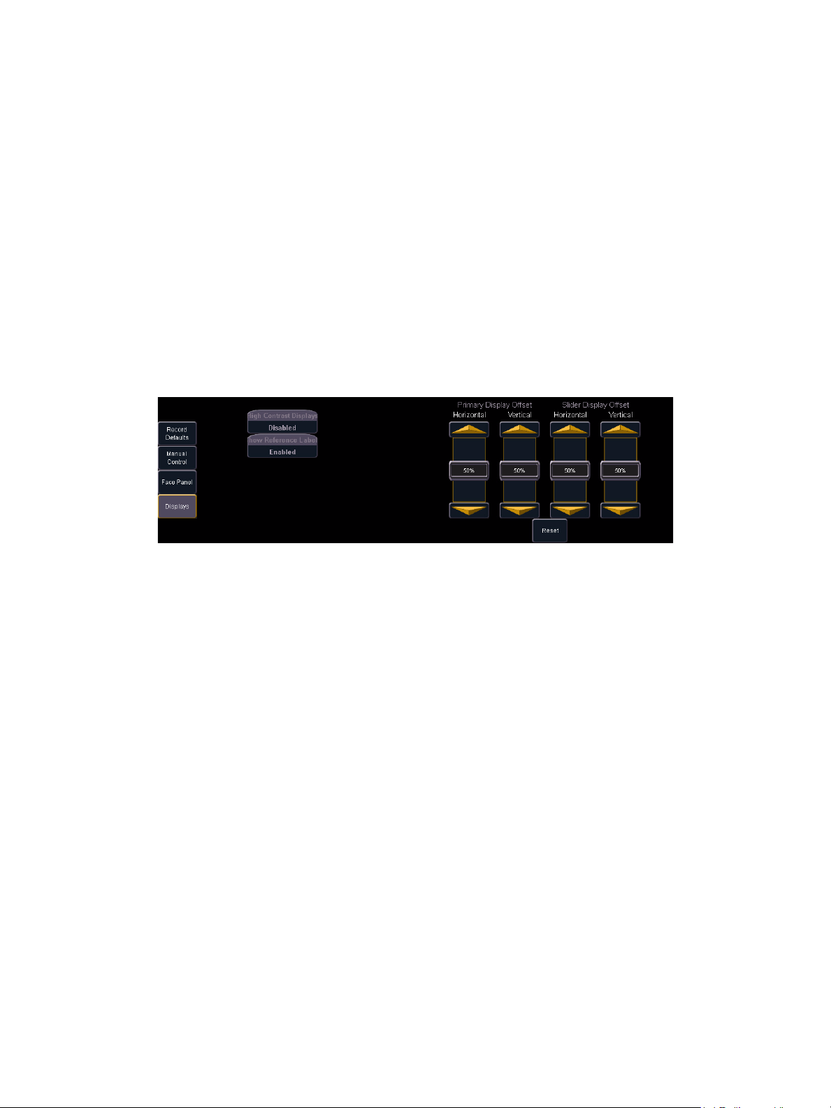
Adjusting the Direct Select View
When using button modules, you may need to adjust the horizontal or vertical alignment of the
direct select arrays, depending on your viewing angle. You can adjust these settings in the “Desk
Settings” in Setup.
To adjust the horizontal or vertical alignment of direct selects:
Step 1: Press [Displays]. The bottom of the CIA repaints to show the display options.
Step 2: Press {Setup}. The CIA repaints to show the setup touchbuttons.
Step 3: Press {Desk} at the bottom of the CIA.
Step 4: Press {Displays} on the left side of the CIA. Four virtual sliders appear; two for the
Primary (central) LCD and two for the Slider (left) LCD.
Step 5: Adjust the virtual sliders using the gold arrows at top and bottom or by touching the
slider bar and dragging it tot he desired level. As it moves, you will see the direct
selects adjust accordingly.
You can return the sliders to their default position at any time by touching the {Reset} touchbutton,
located just beneath the adjustment sliders.
Using Direct Selects
Direct selects allow access to a number of controls, including a channel select display. If there are
more items than can be viewed at once, you may view subsequent pages by using the page
touchbuttons ({Page
When storing to direct selects (groups, palettes, presets, and so on), you may store directly to them
by pressing [Record] {Direct Select Key}. Direct selects are anchored to whole numbers, so targets
will be recorded to the specific location of the direct select. Direct select buttons with no data stored
show a light gray number in the lower right corner. This number indicates the whole number slot of
that button.
You can record decimal inserts to a direct select ({Group 7.1}, {Color Palette 15.5}, {Preset 6.94},
and so on). Doing so will fill un-stored slots in the bank of direct selects, but will not eliminate the
whole numbers those slots represent.
For Example:
Assume you have stored color palette 1 (button 1), color palette 1.1 (button 2), and color
palette 3 (button 3). If you record color palette 2, it will appear in the slot just after color
palette 1.1 and color palette 3 will be bumped one slot to the right. This will continue until
an open slot can absorb the displaced target.
S}, {Page T}) by the direct selects.
30 Eos Operations Manual
Page 45

Selecting Channels with Direct Selects
Channel direct selects are highlighted when selected. Channel selection is generally an additive
process, if channels 1-5 are selected, pressing {Channel 6} adds channel 6 to the selection,
leaving channels 1-5 also selected. Pressing {Channel 6} again will deselect the channel.
It is possible to double hit a channel button. This selects that channel and deselects any previously
selected channels.
When using the button module, pressing and holding a channel button while pressing another
channel button selects those two channels and all channels in between. This behavior is not
supported when channel selects are used on the touch screens without the module.
• {Channel 1} - adds channel 1 to currently selected channels, if not currently selected.
• {Channel 1} {Channel 10} - adds channels 1 and 10 to currently selected channels.
• {Channel 1} & {Channel 10} - adds channels 1 thru 10 to currently selected channels (if
button modules are used).
• {Channel 1} {Channel 1} - selects channel 1, deselects all other channels.
• {Page
• {Page
T} - pages direct selects down by one page.
S} - pages direct selects up by one page.
3 System Basics 31
Page 46

Display Control and Navigation
Opening and Closing Displays
The Live/Blind display is open as tab 1. The playback status display is always open as tab 2.
Neither of these displays can be closed.
Other displays are numbered as they are opened. Tab numbering is useful for navigating to views.
Displays can be opened and closed in different ways, depending on the display. Many displays are
accessible from the browser, while other displays are accessible from the softkeys. The blind
displays of record targets (also called “lists”) can be quickly accessed by double pressing the record
target button (for example, [Preset] [Preset] opens the preset list).
From the Browser
Open and navigate the browser as described in Using the Browser, page 27. When you open a new
display (such as the cue list index, group list, or patch) and it is posted in a tab view, it will open on
monitor 2. If the display does not open as a tab view (such as “setup” or the browser) it will open in
the CIA.
Again, any time you wish to return to the browser, simply press [Displays] and then {Browser} and
it will be made available.
From the Hardkeys
You can open list views of any record target by double-pressing the key for the desired record
target.
From the Softkeys
To open any displays accessible from the softkeys, press [Displays]. The softkeys will repaint to
display:
• Effect Status
• Color Picker
•Patch
• Setup
•
•Browser
Any of these softkeys will open the associated display with a single press.
Closing Displays
To close any Tab display, select the display by using the [Tab] key or other means of navigation.
When the desired display is active, press [Escape] to close it.
To close a display in the CIA, press the [Display] key and the browser will reappear.
32 Eos Operations Manual
Page 47

Selecting Displays
When a display is selected, the screen is highlighted in a gold border and the display name (such
as “1. Live Channel”) will be in gold as well. When a display is not selected, there is no border and
the tab name is grey.
If a display is already open, it can be selected in the following ways:
•Press [Tab] to change focus from the currently selected tab to the tab immediately to the right.
If no tabs are to the right, the selection moves to the first tab on the left of all available monitors.
• Press [Tab] & [n], where “n” represents the tab number of the desired tab.
• Press [Live] or [Blind] to automatically bring live/blind into focus.
• Double press a record target button (such as [Preset] or [Submaster]) to either open the
associated display or select it if it is already open.
Moving Displays
To move the active display from one monitor to another, press and hold the [Tab] key and use the
page arrow keys to move the display in the direction of the desired screen. One press of the left or
right page keys will move the display to the next screen in that direction. To move it back, press the
opposite arrow key.
Scrolling within a Display
By default the page keys will advance/retreat a display by one page per press. However, to scroll
through displays you may press the [Scroll Lock] key on the keypad. The LED on the button
illuminates red when in scroll lock mode.
Scroll lock is a toggle state. When scroll lock is first pressed:
• [Page
• [Page
• [Page
• [Page
T] - scrolls table, spreadsheet and channel views down
S] - scrolls table, spreadsheet and channel views down
X] - scrolls table and spreadsheet views right
W] - scrolls table and spreadsheet views left
Expanding Displays
[Expand] allows a tab to be viewed across multiple external monitors.
To expand a display to an adjacent monitor, press [Expand] & [Page
To collapse an expanded view press [Expand] & [Page
Note: Please note that you must have a minimum of two (2) external monitors attached
to your Eos to use the [Expand] feature.
If the display you are expanding is at the right most position, the display will
expand onto the first (or left most) monitor.
W] or [Expand] & [Page T].
X] or [Expand] & [Page S].
3 System Basics 33
Page 48

Graphical User Interface (GUI) Display Conventions
Channel Number
Straight line under
channel heading
Intensity data (I)
No other parameter
categories
Wavy line under
channel heading
Intensity data (I)
Focus data (F)
Color data (C)
Beam data (B)
Parameter
Category Indicators
Eos relies on many traditional ETC indicators which you may be familiar with, as well as some new
ones. This section identifies the graphical and colorful conventions used in Eos to indicate
conditions to you.
Indicators in the live/blind display
This is the live/blind summary view.
34 Eos Operations Manual
Note: The color and text conventions described below apply regardless of the format of
live/blind being used (see Using [Format], page 40).
Conventionals
Most of the channels in the above image are conventional
channels (intensity is the only available parameter).
Conventionals have a straight line beneath the channel
number. They also display only the top field, intensity, as
no other parameters are available on a conventional
channel.
Moving Lights or Multi-parameter Devices
Several channels in the image are moving lights
(possessing more parameters than only intensity).
Moving light channels have a wavy line beneath the
channel number as well as parameter category indicators
at the bottom of the channel.
This view also has additional data fields beneath intensity
(F, C, B). This information can be suppressed by pressing
[Params] and any parameter category (Focus, Color, or
Beam) in the CIA. Doing so will leave only the intensity
field and FCB indicators at the bottom of the channel.
Page 49

Color indicators
Unselected Selected
Eos uses color to indicate the selection state and information about channel/parameter levels.
Channel numbers/channel headers
• Black . . . . . . . . . . . . Unselected channel number.
• White . . . . . . . . . . . . Selected channel number or channel is parked.
• Gray header . . . . . . Unselected channel header.
• Gold outline . . . . . . Selected channel header.
Channel/parameter levels
• Red.
. . . . . . . . . . . . . Manual Data (any data that has been set but not yet stored to an
active cue).
• Blue . . . . . . . . . . . . . The intensity value is higher than in the previous cue.
Non-intensity parameters (NPs) are in blue when any move
instruction has occurred.
• Green . . . . . . . . . . . . The intensity value is lower than in the previous cue.
Also used in reference marking to indicate a channel has just
marked.
• Magenta. . . . . . . . . . The recorded value is tracked, unchanged from a previous cue.
• White . . . . . . . . . . . . The value is blocked.
• Gray . . . . . . . . . . . . . Default or the value is a null value (from either {Make Null} or a
filter). When nulled, a gray “n” appears next to the value.
3 System Basics 35
Page 50

Text Indicators in live/blind
“B”
“N”
“_” (underscore)
“t”
“A”
“+”
“R”
“CP6”
“MK”
“Q5”
“C”
“I”
Please note examples of text indicators in the following graphic:
Color conventions listed above apply to text indicators as well. Therefore red indicates a manual
value that must be stored.
• _ . . . . . . . . . . . . . . . . Underlined value (white) indicates a system-applied block (also
called an auto-block).
• + . . . . . . . . . . . . . . . . Found in place of parameter data in summary view. Indicates
that not all parameters in that category are at the same value.
This indicator is found only in the summary view or in table views
when the parameters are collapsed into a category view only.
• A. . . . . . . . . . . . . . . . Indicates the channel or parameter is asserted.
• B. . . . . . . . . . . . . . . . Always red. Indicates the channel or parameter is manually
• C. . . . . . . . . . . . . . . . Captured Channel
• I . . . . . . . . . . . . . . . . Channel is controlled by an inhibitive submaster
• IP, CP, FP, BP . . . . . Indicates that the value is referenced to a palette (Intensity,
blocked (not an autoblock). This block must be stored.
Color, Focus, or Beam). This text is followed by a number,
indicating which palette is being referenced. This can be
substituted with the palette label if the “Show Reference Label”
setting is activated (see Show Reference Labels, page 92).
36 Eos Operations Manual
Page 51

• MK . . . . . . . . . . . . . . Indicates the channel is marked for a later cue. The cue number
is indicated in the other categories (see “Q” below).
• N. . . . . . . . . . . . . . . . Indicates the value is null (from either {Make Null} or a filter).
• Pr (not shown) . . . . . Indicates that the value is referenced to a preset. This text is
followed by a number, indicating which preset is being
referenced. The preset label may also be shown if this setting is
enabled (see Show Reference Labels, page 92).
• Q. . . . . . . . . . . . . . . . Found in the non-intensity categories of a marked channel. The
“Q” is followed by a number indicating which cue the mark is in
preparation for.
• R. . . . . . . . . . . . . . . . Indicates a manual reference override. Manual changes have
been made that override a previously stored reference (such as
to a palette or preset). Once recorded, the reference will be
broken. If updated, the referenced target will be updated as well.
• t . . . . . . . . . . . . . . . . The channel has discrete (parameter/category-specific) timing.
[Data] Key
Pressing and holding [Data] allows you to view the values behind any referenced or marked data.
[Data] exposes the next lower reference level. So if you view a palette reference and press [Data],
the absolute data will be displayed instead. If you are viewing a preset, absolute or palette data will
be displayed, depending on what is contained in the preset.
[Time] Key
Pressing and holding [Time] allows you to view discrete timing data behind any channel. [Time]
exposes channel or parameter specific timing for any channels in the current cue. If no discrete
timing is recorded for a channel or parameter, a “--” is displayed, meaning that the channel/
parameter follows the timing specified for the cue. If multiple values are shown, the first value is the
display, the second value is the timing transition.
Using Flexichannel
Flexichannel (use of the [Flexi] key) allows you to view only channels meeting a certain criteria in
the live/blind display, therefore removing unwanted data from view. Flexichannel has several
available states which include allowing you to view only:
• All channels
• All patched channels
• All show channels (any stored data in the show file)
• Active channels
• Moved channels
• Selected channels
In flexi mode, any selected channels (including the last channel selection) are always included in
the view.
To change flexi modes in the live/blind display, press [Flexi] to cycle through the views listed above.
3 System Basics 37
Page 52

Indicators in the playback status display
Color indicators
• Gold . . . . . . . . . . . . . Any item (cue, list, page) highlighted in gold indicates “current”.
Outlined in gold indicates “selected”.
• Green . . . . . . . . . . . . submaster is an additive submaster.
• Red. . . . . . . . . . . . . . Cue fade is in progress (cue list area)
-orsubmaster is an inhibitive submaster or grandmaster (fader
display area).
38 Eos Operations Manual
Page 53

Text indicators
• + . . . . . . . . . . . . . . . . indicates that there is discrete timing within the associated cue
• * . . . . . . . . . . . . . . . . indicates the cue has an allfade command
• A or a . . . . . . . . . . . . indicates an asserted cue. “A” indicates the entire cue is
• B or b . . . . . . . . . . . . indicates a blocked cue. “B” indicates the entire cue is blocked.
• F1 - F10 . . . . . . . . . . indicate faders numbered 1-10 on the console.
• F9 (see in cue 11) . . indicates a follow time associated with the cue (in this case,
• H (see in cue 9) . . . . indicates the cue has a hold time.
• H4 (see in cue 10) . . indicates a hang time associated with the cue (in this case 4
• L2 (on fader pg. 8) . . indicates a cue list number (in this case, list 2).
• M or m . . . . . . . . . . . indicates a marked cue. “M” indicates an AutoMark or a
• R (see in cue 8) . . . . indicates the source cue which refers back to an earlier mark
asserted. “a” indicates a channel or parameter assert only.
“b” indicates a channel/parameter block only.
9seconds).
seconds).
reference mark that is used by a subsequent cue. “m” indicates
a reference mark that is currently unused by any subsequent
cue (see Using Mark, page 171).
(see Referenced Marks, page 173).
• S2 (on fader pg. 1) . . indicates submaster number (in this case, sub 1).
Note: For more details on information contained in the playback status display, see
Playback Status Display, page 44.
3 System Basics 39
Page 54

Using [Format]
Channel numbers
Intensity Data
F, C, B Data
Some displays have multiple formats. When the display is first opened, it opens in its default view.
The default view for Live/Blind is channel summary, with only intensity displayed. When the default
format has been changed, those new settings will be used whenever the display is changed back
to that format.
Live and Blind share formatting. When you change from one format to another format, you are
always working with the same format until you change it. The exception to this is spreadsheet,
which is only available in blind. If you are working in blind spreadsheet, when you return to live you
will be working with the table or summary view, based on which one you were last using.
Summary View
The summary view displays the largest number of channels of any of the formats. Below you can
see channels 1-60 are shown. This format is best used to see large numbers of channels’ intensity
data and/or parameter category data. Individual parameters are not visible in this view
By default, the summary view shows only intensity, with FCB (Focus, Color, Beam) data
suppressed. FCB icons will appear at the bottom of the channel area for channels that have those
parameters patched to them.
You may include focus, color, or beam data in the summary view by holding down the [Params] key
and pressing any parameter category key (located beneath the CIA). This displays all categories.
40 Eos Operations Manual
Page 55

Table View
Expanded Category
Expanded Parameters
Collapsed Category
Channels
Command
Line
Selected cue
information
Table view is available in live or blind. In live, table view displays all output channel data. In blind, it
shows one record target at a time. It shows a smaller range of channels on the vertical axis and
parameter data along the horizontal axis. Parameter categories are always visible in this format,
summarizing the category instruction. The categories can be expanded as needed to provide a
more detailed view of individual parameters, or they can remain suppressed.
To hide/reveal parameters of a certain category from view you may press and hold [Params] and
then press the parameter category button of the parameters you wish to affect. Parameters for that
category will be suppressed/expanded, depending on the current view. You cannot collapse a
category entirely.
To hide/reveal only certain parameters, press and hold [Params] and then press the parameter
buttons of the appropriate parameters in the CIA. The parameters will be displayed or suppressed
depending on the current view.
You will notice that when you hold down the [Params] button, the touchbuttons of parameters that
are currently selected for viewing will be highlighted in the CIA.
3 System Basics 41
Page 56

Packed Table View
Fixture Type
Packed fixtures with
only type-specific
parameters displayed
Packed table view is very similar to table view. The primary difference is that a slight space is
provided between fixture types, giving a clear delineation between them. The name of the fixture
type is also displayed at the top of the section for that fixture.
In addition, packed table view condenses the table to display only the parameters relevant to that
fixture type. Parameters not found in a fixture will not be displayed in that part of the packed table.
Categories can be expanded and condensed using the same conventions as table view.
42 Eos Operations Manual
Page 57

Spreadsheet (Blind Only)
Channel number
Cue numbers
Parameters
Spreadsheet format is available only in blind mode. It is useful for viewing channel data and data
trends for multiple cues, submasters, palettes, or presets at one time. Cues/record targets are
displayed on the vertical axis and channel/parameter data is visible on the horizontal axis.
Since this is a blind-only view, changes made in this view are immediate and do not require a record
or update.
As with table view, spreadsheet format allows you to choose exactly which parameters you want to
view. Parameters can be expanded/suppressed by holding [Params] and pressing the desired
parameter buttons in the CIA. Category data is not available in spreadsheet, but you may hide all
parameters of a specific category by holding [Params] and pressing the desired category button.
3 System Basics 43
Page 58

Playback Status Display
Current cue list
cues
Timing data
Cue flags
Cue attributes
Fader Pages
1-10
Faders1-10
Master cue list timeline
Other cue list
Submasters
The playback status display allows you to view a range of cues in the current cue list, all cue
attributes for those cues, and a view of the fader configurations for 10 pages of 10 faders each (for
a total of 100 visible faders.
Fader Display Format
44 Eos Operations Manual
Page 59

Timeline Format
Fader page
numbers
Fader numbers
Fader timelines
Pressing [Format] with the playback status display active will access this format. In timeline, the
active cue list is still visible in the top half of the display, the timeline is visible in the center, and the
bottom half of the display gives the ability to view ten separate pages of ten faders along with a
timeline of what is occurring on those faders.
3 System Basics 45
Page 60

Expanded Timeline Format
Fader page
number
Fader numbers
Pressing [Format] with the playback status display active will access this format, In expanded
timeline, the view of the active cue list increases to the full size of the display. The current timeline
is still visible at the bottom of the screen, and a summary of the current fader page is displayed
beneath it.
46 Eos Operations Manual
Page 61

Encoders
The encoders are one of two ways to control the non-intensity parameters (NPs) of moving lights.
The bottom two encoders are always in control of pan and tilt respectively from left to right.
The top four encoders are identified by the encoder LCD window, just to the left of the encoder
wheels.
Encoder Navigation
Use the encoder page buttons (located to the left of the encoder LCD) to choose which parameters
are mapped to the encoders. There are four usable buttons: Color, Shutter, Image, and Form.
Pressing any of these will change the parameters controlled.
Some fixtures have more parameters than can be displayed on one encoder page. The number of
pages for each category is displayed at the top of the encoder touchscreen. To view the other
pages, simply press the [Color], [Shutter], [Image], or [Form] button to advance the pages or press
the button with a number key to go directly to the page you want to access.
Encoder Touchscreen
Each encoder’s touchscreen area will display the name of the parameter it controls, display
stepped limits (if any) and also a {Home} button which allows you to set that parameter to its default
position.
The encoder touchscreen allows you to cycle through parameter steps (if available). You can also
home any parameter. Some buttons that may be available on the touchscreen are:
•Min
•Max
•Next
•Last
•Home
•Mode
Buttons like {Next} and {Last} are used to step through parameters (such as colors in a color
scroller) one step at a time. {Min} and {Max} allow you to send a parameter to its minimum or
maximum limit with one press.
{Mode} allows you to switch between modes of a parameter (if any exist); for example, a rotating
gobo wheel. The top mode accesses the index controls for the wheel. Press {Mode} to access
clockwise rotation (encoder controls the speed of rotation); press it again to access counterclockwise rotation.
The touchscreen also indicates when the respective encoders are in coarse or fine mode, which
you can toggle between by pressing the encoder. Press it again to return to the original mode.
An “E” indicates expand. Press this to see all of the information about any device with a frame table.
Press again to collapse to the normal view. You may make selections from the Expand screen. The
colors/images in the device are established in patch (see Using the Scroller/Wheel Picker and
Editor, page 73).
3 System Basics 47
Page 62

Using Softkeys
Some of the features and displays in Eos are accessible from the softkeys, which are located in the
bottom right area of the CIA.
Remember the use of the [Displays] button to the right of the CIA. This button offers softkeys that
access the following displays:
• Effect Status
• Color Picker
•Patch
• Setup
•Browser
Each of these displays offers its own specific softkeys of relevance.
Context Sensitive Softkeys
Softkeys are context sensitive and will change depending on a number of factors including: the
active display, the current command in the command line, the active record target and so on. Eos
always repaints the softkeys to coincide with your current action.
To get the full use of features on your Eos system, be sure to familiarize yourself with the softkeys
that become available as you program your show.
Changing Softkey Pages
When there are more relative softkeys than the six available softkey buttons, both gray and white
softkey labels will be visible. The white labels on the bottom row of the label window indicate the
active softkeys. The gray labels in the top row indicate the second page of available softkeys.
To access the second page of softkeys, press the [More SK] button. To access the previous
softkeys, press [More SK] again.
48 Eos Operations Manual
Page 63

Chapter 4
Managing Show Files
This chapter explains how to create, open, and save your show files. Each of these operations are
accomplished through the Browser area in the CIA.
This chapter contains the following sections:
• Create a New Show File. . . . . . . . . . . . . . . . . . . . . . . . . . . . . .50
• Open an Existing Show File . . . . . . . . . . . . . . . . . . . . . . . . . .51
• Saving an Existing Show File . . . . . . . . . . . . . . . . . . . . . . . . .53
• Using Save As . . . . . . . . . . . . . . . . . . . . . . . . . . . . . . . . . . . . .54
• Importing Show Files. . . . . . . . . . . . . . . . . . . . . . . . . . . . . . . .55
• Exporting a Show File . . . . . . . . . . . . . . . . . . . . . . . . . . . . . . .56
• Deleting a File. . . . . . . . . . . . . . . . . . . . . . . . . . . . . . . . . . . . . .57
4 Managing Show Files 49
Page 64

Create a New Show File
To create a new show file, navigate within the browser to: File> New> and press [Select].
You will be prompted for confirmation that you want to reset the system. Press {OK} to confirm or
{Cancel} to discontinue the operation.
50 Eos Operations Manual
Page 65

Open an Existing Show File
To open an existing Eos show file, navigate within the browser to: File> Open> and press [Select].
Eos provides you with multiple locations to retrieve an Eos show file (.esf) including:
• Show File Archive - This is the default storage location for show files when a show file is
created and saved. Folders are automatically created to store older versions of a show file.
This allows you the ability to open the latest version or an earlier version of a show file if
desired.
• File server - if one is connected. When there is no file server connected, it will not display in
the Browser.
• USB (F:) device - When a USB device is connected and an Eos show file (.esf) is available on
the device, you will notice the USB is displayed in white text and is expandable. When the USB
device is connected and no Eos show file is loaded on the device, you will notice the USB (F:)
is displayed in a grey color and is not selectable.
• CD (E:) drive - When a CD is loaded and an Eos show file (.esf) is available on the CD, you
will notice the CD is displayed in white text and is expandable. When the CD is loaded and
there is no Eos show file (.esf) on the CD, you will notice the CD (E:) is displayed in grey and
is not selectable.
Open the desired location:
• To open a show file from the Show File Archive, navigate within the Browser to: File> Open>
Show File Archive and press [Select].
• To open a show file from the file server, navigate within the Browser to: File > Open> File
Server> and press [Select].
• To open a show file from a USB device, navigate within the Browser to: File> Open> USB (F:)
and press [Select].
• To open a show file from a CD, navigate within the Browser to: File> Open> CD (E:) and press
[Select].
4 Managing Show Files 51
Page 66

Select the specific show file
Deselected show aspects
• Navigate within the specified storage location and select the show file you wish to open, press
[Select].
• If the selected show has multiple time stamps, navigate to the desired revision and press
[Select].
This will open the partial show loading screen in the CIA.
From this screen you can select which aspects of the show file you wish to load. The touchbuttons
at the center of the CIA represent all of the show aspects that you can choose to load. By default all
aspects are selected (gray) and will be loaded. To withhold any show aspects from loading, simply
deselect them in the CIA by touching the respective button.
To reselect all show aspects, press the {Reset} touchbutton and all buttons will return to gray
(selected). To stop the show load process, press the {Cancel} button.
When you have selected/deselected all of the show aspects you require, press the {OK}
touchbutton.
Eos loads the selected show to the console.
Note:
On a partial show open, if any record targets are not opened, any existing data of
that type will remain stored on the console.
52 Eos Operations Manual
Page 67
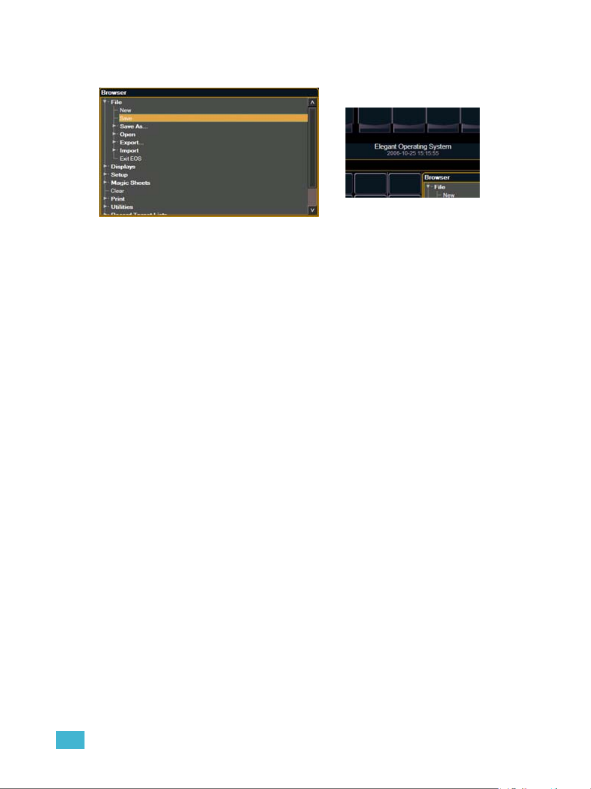
Saving an Existing Show File
To save an existing Eos show file, navigate within the browser to: File> Save> and press [Select].
The Show File Archive is the default storage location for show files when they are saved. The new
time stamp located beneath the show file name on the CIA indicates that the show file has been
saved.
All previous saves are stored in the Show File Archive with the time stamp following the file name.
4 Managing Show Files 53
Page 68

Using Save As
To save an existing Eos show file to a different location or with a different name, navigate within the
Browser to: File> Save As> and press [Select].
Eos provides you with three locations to save an Eos show file (.esf) including the Show File
Archive, the File Server (if connected) or a USB device (if connected).
Navigate to the desired storage location and press [Select]. When using “Save As” to save the
show file to a specific location, the alphanumeric keypad will display on the CIA. Name the show file
and press [Enter]. The show file will be saved in the specified location with the show file name you
entered with a time stamp suffix.
54 Eos Operations Manual
Page 69

Importing Show Files
Eos supports the import of standard USITT ASCII show files.
Note:
You have the option of importing standard USITT ASCII show files (.asc) from the Show File
Archive, a File Server (if connected), a USB device or a CD.
To import an ASCII show file, navigate within the Browser to: File> Import> and press [Select].
Navigate to the desired storage location and press [Select]. When using import, Eos displays only
the available ASCII (.asc) files. Navigate to the specific ASCII file and press [Select].
Eos supports ASCII show file import from a number of other control consoles,
including the Obsession, Expression and Emphasis product lines, as well as the
Strand 500 Series. Please note that all show files must be saved in an ASCII
format prior to importing them into Eos.
4 Managing Show Files 55
Page 70

Exporting a Show File
Export your Eos show file to a standard USITT ASCII show file using the export feature.
To export your Eos show file in ASCII format, navigate within the Browser to: File> Export> and
press [Select]
You have the option of exporting your show file in ASCII format to the Show File Archive, to a File
Server (if connected) or to a USB device.
Navigate to the desired storage location and press [Select]. The alphanumeric keypad will display
on the CIA. Name the show file and press [Enter]. The file will be saved in the specified location
with the file name you entered with a “.asc” file extension.
56 Eos Operations Manual
Page 71

Deleting a File
Eos provides you with the ability to delete show files and ASCII files from the Show File Archive and
the File Server from within the Browser.
To Delete an Eos Show File (.esf)
Navigate within the Browser to: File> Open and press [Select]. Navigate to the desired show file
and press [Delete]. Press [Enter] to confirm or any other key to abort the deletion process.
To Delete an ASCII Show File (.asc)
Navigate within the Browser to: File> Import and press [Select]. Navigate to the desired show file
and press [Delete]. Press [Enter] to confirm or any other key to abort the deletion process.
4 Managing Show Files 57
Page 72

58 Eos Operations Manual
Page 73

Chapter 5
Patch
Patching is very simple in Eos. The extensive fixture library paired with the CIA touch screen
interface make patching your show a simple task.
This chapter contains the following sections:
• Displays . . . . . . . . . . . . . . . . . . . . . . . . . . . . . . . . . . . . . . . . . .61
• Create and Edit Patch . . . . . . . . . . . . . . . . . . . . . . . . . . . . . . .63
• Patching a Dimmer . . . . . . . . . . . . . . . . . . . . . . . . . . . . . . . . .64
• Patching Moving Lights . . . . . . . . . . . . . . . . . . . . . . . . . . . . .66
• Display Pages in Patch . . . . . . . . . . . . . . . . . . . . . . . . . . . . . .68
• Using the Scroller/Wheel Picker and Editor . . . . . . . . . . . . .73
• Changing the Patch View . . . . . . . . . . . . . . . . . . . . . . . . . . . .62
• Adding Keywords in Patch . . . . . . . . . . . . . . . . . . . . . . . . . . .77
• Deleting Channels . . . . . . . . . . . . . . . . . . . . . . . . . . . . . . . . . .77
• Fixture Creator . . . . . . . . . . . . . . . . . . . . . . . . . . . . . . . . . . . . .78
• Update Library . . . . . . . . . . . . . . . . . . . . . . . . . . . . . . . . . . . . .82
5 Patch 59
Page 74

About Patch
Eos treats fixtures and channels as one and the same, meaning each fixture is assigned a single
control channel number. Individual parameters of that fixture, such as intensity, focus, color, and
beam are also associated with that same channel number but as additional lines of channel
information, not as separate channels.
You are required to enter only the simplest data to patch a device and begin programming your
show, such as the channel number, the device type (if needed), and address. Although, when you
provide more information and detail in the patch, you will have more detailed control and improved
function during operation.
One or more devices may be patched to a single channel. For example you may want to patch a
group of dimmers to the same channel. In addition you may patch multiple devices to the same
channel for building a compound or accessorized fixtures. For example a Source Four
scroller and a gobo changer may be patched to a single channel. This is referred to as a compound
channel.
®
with a color
60 Eos Operations Manual
Page 75

Displays
To begin patching your show, you must first open the patch display. You may open the patch display
from the CIA softkeys or from the browser menu.
To open the patch display from the CIA:
Step 1: Press the [Displays] button located to the right of the CIA.
Step 2: Locate and select the {Patch} softkey.
To open the patch display from the Browser:
Step 1: Bring focus to the browser by touching within the browser window. Notice the browser
is highlighted with a gold box to indicate it is selected.
Step 2: Using your finger, mouse, or the page arrows in the navigation keys, select and
expand the Displays submenu.
Step 3: Select Patch either by touching the “Patch” text twice (or double-click with the mouse)
or highlight “Patch” and press [Select].
The patch display will open on an external monitor and the CIA will display patch controls.
Channel View
By default, the patch display lists channels on the X axis and device attributes on the Y axis. In this
view the channels are sorted numerically with the DMX address in the second column. In the “patch
by channel” display, the command line entry defaults to selecting channels.
Address View
You can change the patch display to sort by DMX address by pressing [Format]. The channel
number is now indicated in the second column and the command line changes its default entry to
“Address”. To specify a channel in this mode, use the {Channel} key located in the CIA or press [At]
after the DMX address entry.
5 Patch 61
Page 76

Changing the Patch View
By default, patch is displayed in a sequential channel view. While in the channel patch view, any
numeric entry from the keypad is assumed to be a channel.
Note:
You may change this to a sequential address view by pressing the [Format] button. While in
address patch view, any numeric entry from the keypad is assumed to be an output address.
It is recommended that you use the patch by channel display when working with
moving lights or other multi-parameter devices.
As it is possible to patch by either output address or port/offset, pressing the [data] key will toggle
the display to show the alternate output information.
62 Eos Operations Manual
Page 77

Create and Edit Patch
Select Channel, Set Device Type and Output Address
Each field identified in the patch display is also displayed in the CIA as a touchbutton. You can
select the fields using the page arrow keys (with “scroll lock” engaged) and edit them using the
control keypad or from the CIA touchbuttons.
Selecting Channels
You may select channels for patching and editing using the keypad or direct selects.
Keypad
Channels may be selected in all of the same methods as defined in Selecting Channels, page 96.
When channels are selected, the patch display will show those channels and highlighted in gold.
After selecting the channel or group of channels, you may set each of the attributes beginning with
the device type, followed by the starting address. See “{Patch} Display and Settings” on page 68.
Note:
Direct Selects
Channels may be selected using the direct selects. See Select Channels From the Direct Selects,
page 98 for more information.
When patching conventional dimmers, it is not necessary to specify the device
type. “Dimmer” is assumed.
Status in the Patch Display
The first column in the patch display will advise you when a channel requires your attention.
• “!” is displayed next to a channel number when there is a problem with the patch or to
indicate there is an error.
5 Patch 63
Page 78

Patching a Dimmer
Tutorial
Step 1: To patch a dimmer you must first open the patch display. You may open the patch
display from the browser or by pressing [Displays]>{Patch}.
Step 2: Enter a channel number from the control keypad.
• When typing any number from the control keypad, and patch is in default
channel mode, channel is assumed and is placed on the command line.
Note:
Step 3: Enter the DMX address or addresses.
Step 4: By default, Eos outputs both EDMX and ACN for each address. In a very large
Step 5: Select the {Database} softkey to specify notes and keyword text related to the
If you create several addresses with multiple parts, you can select the same part for multiple
channels by selecting a channel range and using the {Part} key:
Alternatively, when patch is in address mode, DMX address is assumed and is
placed on the command line. Channel mode and address mode are toggled using
the [Format] key in the patch display.
• You can also use the [+], [-] and [Thru] keys to make your channel selection to
patch more than one dimmer at once.
• [1] [Thru] [5] [0] [At] [1] [Enter] patches channels 1 through 50 to
addresses 1 through 50 sequentially.
• You may press [At] and enter the DMX address using the control keypad. The
DMX address may be entered in standard format ([1] [0] [2] [5] [Enter]) or by
using the port and offset value ([3] [/] [1] [Enter]).
• Multiple addresses may be patched to a channel in a single command. For
example, [1] [0] [At] [1] [0] [5] [+] [2] [0] [5] [+] [3] [0] [5] [Enter] would patch
channel 10 to address 105, 205, and 305. When more than one device is
patched to a channel, Eos automatically creates parts for each device. This is
used if you need to access an address directly in the patch-by-channel display.
system, it may be useful to specify the address’s device interface as EDMX (net 2) or
ACN (net 3) to reduce network traffic. Generally, this step is not required. To select a
device interface, press {Interface}.
• This displays three buttons labeled [ACN], [EDMX], and [All]. Select an interface
for the selected device. Once your selection is made, the command line will
populate with the correct interface after the address and terminate.
selected channel for reference and future queries.
• Pressing the {Notes} and/or a {Text} button opens the virtual keyboard on the
CIA. Pressing [Enter] returns the CIA to the database page.
• [5] [Thru] [9] [Part] [2] [Enter] - selects only part 2 of channels 5-9.
64 Eos Operations Manual
Page 79

Dimmer doubling
You can patch channels in Eos to accomodate for dimmer doubling with Sensor+ dimmer racks.
This is done using the softkeys available in patch ({No Dim Dbl}, {A}, and {B}).
For Example:
Let’s assume you patch 96 channels of dimmers to addresses 1-96.
• [1] [Thru] [9] [6] [At] [1] [Enter]
Now you wish to dimmer double 1-12 of your Sensor+ rack and you want these to be
channels 97-108. To patch this, press:
• [9] [7] [Thru] [1] [0] [8] [At] [1] {B} [Enter]
Channels 97-108 are patched to address 1-12 B, while channels 1-12 are now patched to
address 1-12 A.
To remove the dimmer doubling from these addresses, you must first press [Format] to
enter Address mode and then press:
• [1] [Thru] [1] [2] {NoDimDbl} [Enter]
Addresses 1-12 have been returned to single dimmer modes and channels 97-108 are now
deleted.
By default, doubled dimmers start with an offset DMX address value of 20000. Therefore, in the
above example, address 1B (channel 97) is actually controlled by DMX address 20001. Address 2B
is actually controlled by DMX address 20002 and so on. This offset matches the default offset in
CEM+ when configuring your Sensor+ dimmer rack for dimmer doubling. To change the default
offset value, see Show Settings, page 85.
Moving Channels
Channels can be moved from one location to another within patch.
• [1] [Copy To] [Copy To] [7] [Enter]
The second press of the [Copy To] key changes the command into a “Move To”.
This syntax will move the patch information for channel 1 to the patch for channel 3. All data in the
show file that was stored at channel 1 is also move to channel 3.
Unpatch a channel
To unpatch a channel while in patch you can press:
• [n] [At] [0] [Enter]
Unpatched channels can still be manipulated and can have data stored for them, but they do not
output any information (as they are unpatched).
5 Patch 65
Page 80

Patching Moving Lights
The process of patching moving lights requires more detail than patching a dimmer. Specific
information is required for more advanced control of the features offered by moving lights.
Tutorial
Step 1: To patch a moving light you must first open the patch display. You may open the patch
display from the browser or by pressing [Displays]>{Patch}.
Step 2: Enter a channel number or multiple numbers from the control keypad.
• When typing any number from the control keypad, and patch is in default
channel mode, channel is assumed and is placed on the command line. You
can use the [+], [-] and [Thru] keys to make your channel selection.
•example: [1] [0] [1] [Thru] [1] [1] [0]
Note:
Step 3: Press the {Type} touchbutton in the CIA.
Step 4: Select a device type from the fixture library.
Note:
Step 5: Enter a starting DMX address for the selected channel or group of channels.
Alternatively, when patch is in address mode, DMX address is assumed and is
placed on the command line. Channel mode and address mode are toggled using
the [Format] key in the patch display.
a: Press {Manufacturer} from the CIA to display the fixture library. The two
columns on the left are pagable and show manufacturer names.
b: Use the arrow touchbuttons to scroll the list of manufacturers. Selecting a
manufacturer repaints the device columns with all devices from that
manufacturer that are available for patching.
c: Scroll through the device list and make your selection. After the selection is
made, the fixture/device type will be placed on the command line after the
channel number and displayed in the box beneath the {Type} button.
Notice the two softkeys {Show}, {Manfctr}, and {User} located beneath the CIA.
These softkeys provide you with the option of showing only the library of fixtures/
devices that are already patched in the show {Show} or all fixtures/devices
available in the library sorted by manufacturer {Manfctr}.
{User} displays user-defined devices. For more information, see Fixture Creator,
page 78.
• Press [At] and enter the DMX address using the control keypad. The DMX
address may be entered in standard format ([1] [0] [2] [5]) or by using the port
and offset value ([3] [/] [1]).
66 Eos Operations Manual
Page 81

Step 6: To select a device interface (optional), press {Interface}.
• This displays three buttons labeled {ACN}, {EDMX}, and {All}. Select an
interface for the selected device. Once your selection is made, the command
line will populate with the selected interface and terminate.
Step 7: Select the {Attributes} softkey to set detailed moving light attributes.
• The following softkeys are available from this page: {Invert Pan} and {Invert Tilt},
{Swap}, {Scroller}, {Gobo Wheel} and {Color Wheel}.
• If your moving light includes parameters such as a color scroller or gobo
wheel and you have custom gels or non-standard pattens installed, use the
Scroller/Wheel Picker and the Editor to modify the device patched (See
Using the Scroller/Wheel Picker and Editor, page 73). The more specific your
patch data (including accurate colors and patterns) the more detailed
programming and operating will be.
Step 8: Select the {Database} softkey to specify notes and keyword text related to your
selected channel for reference and future queries.
• Pressing the {Notes} and/or a {Text} button opens the virtual keyboard on the
CIA. Pressing [Enter] returns the CIA to the database page.
Patching a Compound Channel
A compound channel consists of any channel that controls more than one device. It can cionsist of
mutliple dimmers patched to the same channel or accessories patched to a channel (such as a
fixture with a color scroller, a fixture with a gobo wheel, and so on).
To patch a compound channel in channel format:
• [8] [Part] [2] [At] [5] [1] [3]
This will create a part 2 for channel 8 and address it at output 513. If you wish to patch by
address while in the channel view, press:
• {Address} [5] [1] [3] [At] [8] [Enter]
This will perform the same action as the previous example, assuming channel 8 was
previously patched to an address.
To patch a compound channel in address format:
• [5] [1] [3] [At] [8] [Enter]
This will perform the same action as the previous example, assuming channel 8 was
previously patched to an address.
CAUTION:
It is recommended that you do not patch more than one multiple-parameter device
(such as moving lights) to the same channel.
5 Patch 67
Page 82

Display Pages in Patch
Softkeys available for use while in patch include {Patch}, {Attributes}, and {Database}. Pressing any
of these softkeys opens a paged view of the patch display and redraws the CIA to an expanded
view of fields related to the selected page.
When creating and editing your patch, page through each of these softkeys individually to enter
more specific data about your selected device.
{Patch} Display and Settings
When patch is opened, Eos defaults to this display. It provides access to data input fields that you
may use to define devices in your lighting system..
• {Channel} - In the patch display, all channels are displayed in numerical order. When multiple
devices are patched to the same channel, the channel number is only displayed in the first
row, additional devices are indicated with part extensions (example P2) on the next row of the
table.
• Select the channel number using the control keypad or the direct selects.
• {Type} - It is not necessary to specify “type” when patching dimmers, Eos defaults to patching
dimmers. To specify a specific device type for the selected channel, press the {Type} button
from the CIA.
• The two columns on the left side of the CIA are pagable and show manufacturer names
by acronym. The four columns to the right of the manufacturer’s list are pagable
devices that are available from the selected manufacturer for patching.
• Selecting a specific manufacturer repaints the display with all devices that are
available from that manufacturer. After you select a device, the fixture/device type
appears in the command line, in the {Type} box in the CIA, and in the “Type” field
for that channel in the patch display.
68 Eos Operations Manual
Page 83

• {Address} - A required entry field for any device. You may use the [At] key rather than the
{Address} button.
• Use the keypad to define the starting DMX address for the device (from 1 to 32767) or
a port and offset value.
Note:
• You may enter a start address without defining an end address. Eos will draw this
• If you specify a start address that conflicts with other channels already patched, the
• {Interface} - An optional field used to specify what network interface should be used for the
output. When the field is left blank, the data is output on both EDMX and ACN. You may
choose EDMX only, ACN only, or All.
Below are some examples of patching from the {Patch} display:
Patching a generic dimmer:
[1] [At] [5] [Enter] - patches channel 1 to output 5.
[1] [Thru] [2] [4] [At] [1] [Enter] - patches channel 1-24 to outputs 1-24.
Patching a moving light:
[2] {Type} {ETC} {Revolution IR/FR} [At] [1] [1] [Enter] - patches an ETC Revolution
fixture to channel 2, with a starting output address of 11.
Press and hold the [Data] key to show the complimentary value. For example if
you have entered address value 514, the complimentary value would be port and
offset value 2/2.
information from the library data. If you wish to leave a larger output gap than required
by the library, use [Offset]. See Using {Offset} in Patch, page 72.
conflicting channels will be unpatched.
5 Patch 69
Page 84

{Attribute} Display and Settings
The {Attributes} page provides you with optional fields for additional information and details about
the configuration of your rig. Attribute settings include {Label}, {Proportion}, {Invert Pan}, {Invert Tilt}
and {Swap}.
When the selected device includes a color scroller, a {Scroller} button will be displayed in the CIA,
when the selected device includes a color wheel and/or a gobo wheel, {Color Wheel} and/or {Gobo
Wheel} buttons will appear.
Press the desired attribute button and use the keypad to set the attribute value.
• {Label} - An optional user-defined label. You can use the {Label} softkey button on the CIA or
the [Label] key to display the virtual keyboard on the CIA.
• [1] [At] [5] {Label} <S4 house right> [Enter] - patches channel 1 to output 5 and labels
channel it “S4 house right”.
• {Preheat} - This field allows you to specify an intensity value for moving lights that will be
applied prior to any intensity move above 0%. This preheat level will occur in the cue
immediately preceding the cue with the intensity move instruction.
• [1] {Preheat} [1] [0] [Enter] - channel 1 is assigned a patched preheat value of 10%.
A preheat value can be assigned at any time using the {Preheat_On} softkey in live.
• {Proportion} - A dimmer attribute to set a modifier for the intensity of the device. If the patch
limit is set at 90% (for example), the actual output will always be 10% lower than the specified
intensity parameter, as impacted by the various output masters. This value is set numerically
in a range of 0% to 200%.
• [1] [At] [5] {Attributes} {Proportion} [1] [2] [5] [Enter] - patches channel 1 to dimmer
output 5 and applies a 125% proportion.
• [1] [At] [5] {Attributes} {Proportion} [Enter] - removes the applied proportion from
channel 1.
• {Curve} - Used to assign a curve to an address in patch.
From channel view:
• [1] {Curve} [4] [Enter] - applies curve 4 to the address assigned to channel 1.
• [2] [Part] [3] {Curve} [3] [Enter] - applies curve 3 to the address assigned to channel
2, part 3.
From address view:
• [3] {Curve} [3] [Enter] - assigns curve 3 to output 3.
• [3] [/] [2] {Curve} [4] [Enter] - assigned curve 4 to universe 3, address 2.
• {Invert} - A moving light attribute used to invert the output of pan, tilt, or both. Select either the
{Invert Tilt} or the {Invert Pan} button on the CIA.
• [2] {Type} {ETC} {Revolution IR/FR} [At] [1] [1] {Attributes} {Invert Pan} - patches
channel 2 with an ETC Revolution fixture at address 11 and inverts the output of the
pan parameter.
70 Eos Operations Manual
Page 85

• {Swap} - A moving light attribute used to exchange pan and tilt levels. Select the {Swap}
button on the CIA.
• [2] {Type} {ETC} {Revolution IR/FR} [At] [1] [1] {Attributes} {Swap} - patches
channel 2 with an ETC Revolution fixture at address 11 and swaps the pan and tilt
levels.
• {Scroller} - An attribute used to change the scroll loaded in a scroller or moving light. Select
the {Scroller} button on the CIA to display the scroller picker and the scrolls available for your
device. See “Using the Picker” on page 73.
• [2] {Type} {ETC} {Revolution IR/FR} [At] [1] [1] {Attributes} {Scroller} - patches
channel 2 with an ETC Revolution fixture at address 11 and opens the Scroller Picker
in the CIA for scroll selection.
• {Gobo Wheel} - An attribute used to change the gobo wheel loaded in a moving light. Select
the {Gobo Wheel} button on the CIA to display the wheel picker with gobo options available
for your device. See “Using the Picker” on page 73.
• [3] {Type} {ETC} {Revolution SWW/IR} [At] [4] [5] {Attributes} {Gobo Wheel} patches channel 3 with an ETC Revolution fixture at address 45 and opens the Wheel
Picker in the CIA for gobo wheel selection.
• {Color Wheel} - An attribute used to change the color wheel loaded in a moving light. Select
the {Color Wheel} button on the CIA to display the wheel picker with the options available for
your device. See “Using the Picker” on page 73. “More” as shown in the patch display,
indicates additional parameter properties are available for the selected device, such as the
color and gobo wheels.
• [4] {Type} {VariLite} {VL2000 Spot Standard} [At] [1] [5] [0] {Attributes} {Color
Wheel} - patches channel 4 with a VariLite VL2000 Spot fixture at address 150 and
opens the wheel picker in the CIA for color wheel selection.
5 Patch 71
Page 86

{Database} Display and Settings
The {Database} page provides you with additional fields for entering information that can be used
by the “Query” function. See “Using [Query]” on page 208. These fields include {Notes} and {Text 1}
through {Text 4}.
• {Text} - Text fields are used to provide up to four keywords about any channel or group of
channels. These fields can be anything that you think is important about a channel, such as
its location (FOH), an attribute of it (wash, spot) or other characteristics of the channel (such
as gel R80). You may use the virtual keyboard in the CIA, or an external keyboard, to provide
up to 30 characters of key words about the device.
• [5] {Database} {Text 1} < FOH right> [Enter] - adds text to channel 5.
• {Notes} - Provides you the ability to attach a text note to a channel or group of channels.
Select the {Notes} button on the CIA to display the virtual keyboard. You may type a label or
any length of note regarding your channel in this space.
• [5] {Database} {Notes} <this fixture is a backup to channel 15 for front of house right
/ new lamp installed on 10/4/06> [Enter] - adds a note to channel 5.
Using {Offset} in Patch
Using the {Offset} feature in patch allows you to force a numerical offset between the starting
address of channels in patch or for offsetting your channel selection. This feature is useful when
you have configurable devices in your show such as a Source Four Revolution which has option
slots for additional addresses (scrollers, indexing pattern wheels, and so on). A fully configured S4
Revolution requires 31 DMX slots.
• [1] [Thru] [5] {Type} {Source Four Revolution} [At] [1] {Offset} [3] [1] [Enter] - fixtures will
be patched with a patch address offset of 31 channels, allowing you to have additional space
within the patch for a given fixture type regardless of configuration or personality.
• [1] [Thru] [2] [0] {Offset} [2] {Type} {Source Four Revolution} [At] [1] {Offset} [3] [1]
[Enter]- selects every other channel in the list and patches them with an offset of 31
addresses.
72 Eos Operations Manual
Page 87

Using the Scroller/Wheel Picker and Editor
Select the
attribute for the
channel to open
the picker.
Select the
scroll / wheel
type.
The scroller and wheel picker allows you to choose a specific scroll, color wheel, or gobo wheel
from standard manufacturers and associate them with fixtures. You may also create customized
scrolls/wheels using the editor to match custom devices installed in your fixture.
Using the Picker
Default color and pattern media for the selected fixture, as determined in the fixture library, is
displayed in the {Attributes} page. Only the media attribute that is available for the selected fixture
will display.
In the sample image below, the selected channel (1) is a Source Four
scroller. If the selected channel included a color wheel and two gobo wheels, each device would be
represented in the display with a button.
®
Revolution® with a color
The picker displays on the left half of the CIA when you select the specific attribute ({Scroller},
{Color Wheel} or {Gobo Wheel}). The picker displayed is specific to the selected attribute (the scroll
picker will display when {Scroller} is pressed, the color wheel picker will display when {Color Wheel}
is pressed, and so on).
5 Patch 73
Page 88

The picker displays buttons for the standard scroll or wheel type of the selected channel. The
default selection is the wheel as shipped from the manufacturer (derived from the fixture library).
Displayed to the left of the standard scroll/wheel selection is a list of each color/gobo as they are
installed in the selected device (frame by frame). When the color or pattern image is available, it will
display next to the frame name.
In the above image, {ETC Scroll} is the default scroll for the selected ETC Source Four Revolution.
The list of gel colors as they are installed in the scroll are displayed to the left with a color chip for
easy reference. Selecting any other type, such as {Martin Scroll}, redraws the frame list to match.
The softkeys displayed beneath the picker are {Clear}, {New}, {Copy}, {Edit} and {Delete}.
• {Clear} - clears the selection type from the selected channel in the picker.
• {New} - creates a new scroll or wheel and provides additional softkeys to enable the Editor.
See Using the Editor below.
• {Copy} - makes a copy of the currently selected scroll/wheel type, which can then be edited
using the editor. See Using the Editor below.
• {Edit} - used to edit an existing scroll or wheel.
• {Delete} - used to remove the selected frame only from a scroll or wheel that you have created.
Using the Editor
The editor is used to create new or edit copied scrolls and wheels. While in the picker display, you
can create a new scroll or wheel by pressing the {New} softkey or make a copy of an existing scroll
or wheel by selecting the source, then pressing the {Copy} softkey.
The editor does not limit how many frames you can add to the scroll or wheel for the selected
fixtures. Keep in mind that any fixture has its own limitations. For example, a Source Four
Revolution color scroller is limited to 24 frames. If you have created a custom color scroll with 30
frames, the Source Four Revolution will only provide you access to the first 24 frames that you
created. This applies to wheels as well.
When using the editor, the following softkeys are available for use:
• {Insert} - inserts a new frame above the selected frame.
• {Delete} - removes the selected frame.
• {Edit} - changes the selected frame.
• {Done} - completes the editing process.
• {Label} - displays the virtual keyboard on the CIA for labeling the new scroll or wheel.
74 Eos Operations Manual
Page 89

Creating a new scroll or wheel
The media selection includes the following softkeys:
• {Gel}, {Color}, {Gobo} and {Effect} - each will display
available media selections as they are cataloged by
the associated scroll or wheel manufacturers
• {Open} - places the frame in Open White. Generally,
the first media frame is open.
• {Cancel} - cancels the media selection and returns to
the frame editor.
Manufacturer
List
Manufacturer
catalog
cataloged media
(sorted numerically)
When you create a new scroll or wheel, {new wheel} appears in the wheel list as the selected
button. The frame list will be empty with only “New” displayed in frame 1.
You can label the new wheel by pressing the {Label} softkey and typing the desired label on the
virtual keyboard and pressing {Enter}.
To select a color or pattern for the specific frame in the scroll/wheel, select the “NEW” text. The
available gel, color, gobo and effect media selections will be displayed.
When a manufacturer is selected from the list, the catalog selection changes to display only the
selected manufacturer’s offerings. When a specific catalog is selected, the media will display in the
last three columns of the editor.
When you make a media selection, the display returns to the new wheel frame list where additional
frames can be added to the scroll or wheel (using the {New} frame button) or you can touch/click in
the next frame area to add more frames.
5 Patch 75
Page 90
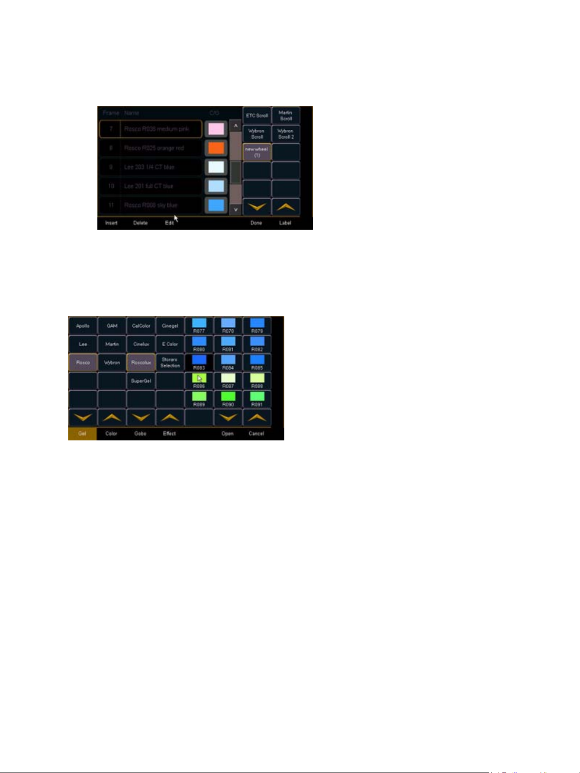
Editing a copy of a scroll or wheel
The media selection includes the following softkeys:
• {Gel}, {Color}, {Gobo} and {Effect} - each will display
available media selections as they are cataloged by
the associated scroll or wheel manufacturers
• {Open} - places the frame in Open White
• {Cancel} - cancels the media selection and returns to
the frame editor.
Manufacturer
List
Manufacturer
catalog
cataloged media
(sorted numerically)
If a copy has been made of an existing scroll or wheel, the copied scroll or wheel will display as
{new wheel} beneath the standard manufacturer offerings. The frame list will include an exact
duplicate of the copied selection.
To make a change to a frame you must first select the frame then press {Edit} to display the media
selection. Or you can insert a new frame above a selected frame using the {Insert} softkey.
For example, to insert a new frame in between existing frames 2 and 3, select frame 3 and press
the {Insert} key. The media selection will display.
When a manufacturer is selected from the list, the catalog selection changes to display only the
selected manufacturer’s offerings. When a specific catalog is selected, the media will display in the
last three columns of the editor.
When you make a media selection, the display returns to the new wheel frame list where additional
frames can be edited in the scroll or wheel.
76 Eos Operations Manual
Page 91

Adding Keywords in Patch
If you plan on being able to query channels based on a keyword association, the keyword must be
defined in patch.
To enter a keyword for a channel:
Step 1: Press [Displays], to the right of the CIA.
Step 2: Press {Patch} at the bottom of the CIA.
Step 3: Press {Database}.
Step 4: Select a channel or range of channels in the command line.
Step 5: Touch one of the {Text (1-4)} touchbuttons in the CIA to specify which keyword you
are entering. The virtual keyboard will appear.
Step 6: Type the keyword or words you wish to use. You may use either the virtual or external
keyboard.
Step 7: When finished, press [Enter].
Once keywords have been created, they will appear in the keyword section of the CIA when a query
is performed. For more information on keyword queries see Using [Query], page 208.
Deleting Channels
It is possible to delete channels in patch. Deleting channels is different from unpatching in that
deleted channels cannot be manipulated or have parameter data stored for them. When deleted,
the channel numbers will still be visible in the live/blind display, but the channel outline, containing
the parameters and level information, will be removed from the display.
For Example:
To delete channels in the patch display, press:
• [6] [Thru] [1] [0] [Delete] [Enter] [Enter]
In the live blind display, the channel numbers will still be visible but the channel outlines and
parameter data will be hidden from view.
5 Patch 77
Page 92

Fixture Creator
Eos provides you with the ability to create your own fixture type within patch and store it with your
show file. You can name the fixture, assign all necessary parameters, define the address of those
parameters, and specify the operational range of them as well.
Note:
The fixture creator is accessible from patch. Once a fixture has been created, it is stored in the
show file. It is not added to the fixture library.
To open the fixture creator:
Step 1: Press [Displays]>{Patch} to open the patch display. Or you may open it from the
Step 2: Select any channel (it need not be the channel for the fixture you are creating, but it
Step 3: Press {Type} in the CIA patch display. The left side softkeys will change to offer fixture
Step 4: Press {User}. This will display touchbuttons for all currently patched fixtures in the
Step 5: Press {Edit}. This will open a list displaying those same fixtures that are currently
You cannot edit existing fixture library data from the fixture creator. You must
create a new fixture entirely to customize any fixture for your show.
The ability to edit fixture library data will be available in a future release.
browser.
can be) from the keypad.
type options.
CIA.
patched. This is the fixture creator.
78 Eos Operations Manual
Page 93

Creating a New Fixture
New fixtures are created from the fixture creator list in the CIA (see above).
To create a new fixture, press {New}. A new fixture will be added to the bottom of the fixture list.
Name New Fixture
Once the new fixture appears in the list, it is recommended that you name the fixture you are about
to create.
To name a fixture in the creator list:
Step 1: Press [Page
Step 2: Press {Type}. The virtual keyboard will open in the CIA.
Step 3: Enter the desired name for the new fixture on the virtual (or attached alphanumeric)
keyboard.
Step 4: Press [Enter]. The name will appear in the “Type” column for the new fixture.
T] to arrow down to the new fixture.
Add parameters
After naming the fixture, you can specify which parameters the new fixture contains.
5 Patch 79
Page 94

To add parameters to a new fixture:
Step 1: Use the [Page] keys to select the new fixture from the fixture list.
Step 2: Press {Edit}. That fixture will open in a new display in the CIA.
Step 3: Determine the total number of parameters that your fixture has. Do not count 16-bit
channels as two channels, this will be done in a later step.
Step 4: Press {New} to add parameter slots. Repeat this step until you have as many slots as
are required by the number determined in step 1.
Note:
Step 5: Use the [Page] keys to navigate to any parameter slots that you wish to alter the
Step 6: When you have selected a slot, press {Parameters}. The CIA will display
The touchbuttons on the left side of the CIA can be used to speed your search. You may
press them to see only parameters that fall into the specific categories of {Intensity},
{Focus}, {Color}, {Image}, {Form}, {Shutter}, or {Control}. {All} returns you to the complete
list of parameters.
When {New} is pressed, the parameter slot will appear in the list with a default
name in the “Parameter” column. You may disregard these default parameters as
you will redefine the designations in a later step.
default parameter designations for.
touchbuttons representing all of the available parameters.
a: Use the {>>} and {<<} buttons to scroll through the available parameters (in
alphabetical order).
b: Use the parameter category buttons on the left of the CIA to expedite
searching for a particular parameter.
80 Eos Operations Manual
Page 95

Step 7: Press the touchbutton for the desired parameter in the CIA.
Step 8: Repeat steps 3-5 until you have entered all of the required parameters for the new
fixture.
If you are missing a parameter slot: At any point you can use the [Page] keys and
{Insert}, to insert a parameter slot above the selected one.
If you want to remove a parameter: you can use the [Page] keys and {Delete}, to remove
a parameter from the list.
Define parameter channels
Once you have added and specified all of the parameters for the new fixture, you can now define
the address requirements, size, and ranges for each of them.
To define the size (8-bit or 16-bit) of any parameter:
Step 1: Use the [Page] keys to navigate to any parameter that you wish to alter the size of.
The system defaults to 8-bit for any new parameter.
Step 2: When selected, press {Size}. This will toggle the parameter from 8-bit to 16-bit. If 16-
bit is selected, the system automatically applies a value in the “LDMX” column. This
value can be altered (see below).
To define the DMX address of any parameter:
You can alter the default DMX address assigned to any parameter in the list. This is not the actual
address that will be used when patched, but rather it is the order of address for the parameter
relative to the other parameters in the fixture.
Step 1: Use the [Page] keys to navigate to the “DMX” column of the desired parameter.
Step 2: Enter the desired address using the keypad.
CAUTION:
To define the LDMX address of any 16-bit channel:
LDMX or “low-DMX” is the DMX address for the second half of any 16-bit channel. If used in
Coarse/Fine determination. The DMX channel defines the “Coarse” adjustment and the LDMX
defines the “Fine” adjustment.
Step 1: Use the [Page] keys to navigate to the “LDMX” column of the desired parameter.
Step 2: Enter the desired address using the keypad.
CAUTION:
Be careful not to duplicate any address in the DMX order of parameters in the new
fixture. Eos does not prevent you from duplicating addresses.
Be careful not to duplicate any address in the DMX order of parameters in the new
fixture. Eos does not prevent you from duplicating addresses.
5 Patch 81
Page 96

To alter the Home settings for any parameter:
You can define the value for any parameter’s “home” value.
Step 1: Use the [Page] keys to navigate to the “Home” column of the desired parameter.
Step 2: Enter the desired home value (0-255) using the keypad.
Range editing a parameter
You can enter the operational ranges for specific slots within any specific parameter (such as color
scroller, color wheel, gobo wheel, and so on).
For example, if the parameter were “Gobo Wheel”, and the fixture included a four-slot gobo wheel,
you can use ranges to determine the minimum/maximum values for each of those slots. You can
also label the slots and define the minimum/maximum values that will appear in the channel display
for that parameter.
To define the range values for any parameter:
Step 1: Use the [Page] keys to navigate to the parameter that you want to add ranges to.
Step 2: Press {Ranges}. The range list will open.
Step 3: Determine the total number of slots required by the parameter. Be sure to include
“open” slots when needed.
Step 4: Press {New} to add ranges. Repeat this step until you have as many slots as are
required by the number determined in step 3.
Step 5: Use the [Page] keys to select the range and field you wish to edit. Fields are:
• Min - enter the minimum value (0-255) for the range slot you are defining.
• Max - enter the maximum value (0-255) for the range slot.
• User Min - enter the value that will be displayed to users (for example, what will be
displayed in the live summary view) when the slot is at its minimum value. Value
can range from -9999 to 65535.
• User Max - enter the value that will be displayed to users when the slot is at its
maximum value. Value can range from -9999 to 65535.
Step 6: Press {Label} to add a label to any range slots. These will appear in the encoder LCD
when the related parameter is displayed for the new fixture.
Step 7: Press {Done} when you have finished editing the ranges.
Update Library
When a new library is installed on Eos (for example, included in a software update), changes in
library data will not automatically update your show files. This is to prevent library changes from
affecting a functional show file.
In the event that you wish to update the show’s fixture data to match a new library, you may enter
the fixture creator (see Fixture Creator, page 78) and press {Update Lib}. This will update the show
file fixture data with any relevant changes from the new fixture library.
82 Eos Operations Manual
Page 97

Chapter 6
Setup
This chapter describes the processes involved in changing your system settings to meet your
preferences. It also covers advanced setup functions as well.
This chapter contains the following sections:
• Opening Setup . . . . . . . . . . . . . . . . . . . . . . . . . . . . . . . . . . . . .84
• Show . . . . . . . . . . . . . . . . . . . . . . . . . . . . . . . . . . . . . . . . . . . . .84
• Desk . . . . . . . . . . . . . . . . . . . . . . . . . . . . . . . . . . . . . . . . . . . . .88
• Security. . . . . . . . . . . . . . . . . . . . . . . . . . . . . . . . . . . . . . . . . . .93
6 Setup 83
Page 98

Opening Setup
To enter the setup screen, press {Displays}>{Setup}.
The CIA will repaint to display the setup screen and the softkeys will change to display the various
subcategories of setup. Eos defaults to display show settings, however if you have changed the
view to another subcategory, Eos will remember the view you were in when you return to setup.
The setup subcategory softkeys are:
•Show
•Desk
•Security
Show
When you select the {Show} softkey, the CIA repaints to display the following screen:
The buttons on the left are the setting categories within show setup. The show setup categories are:
• Show settings
• Cue settings
• Fader configuration
• Filter setup
• Encoder configuration
• Partition Configuration
• Show Control
84 Eos Operations Manual
Page 99

Show Settings
Press {Show Settings} to enter this category.
Three fields will be available to you: {Num of Channels}, {Auto-Mark}, and {Partitioned Control}. To
change the setting for any of these fields, press the field in the CIA to activate it. If the field requires
data, enter it from the keypad. If the field is a toggle state, one press of the button will switch the field
to its other state.
Changes from this screen are systemwide and will impact all Eos consoles and clients connected to
the system.
{Num of Channels}
You may use this field to set the number of channels in your Eos to the number of channels in your
system. Eos supports a maximum of 5000 channels. Enter the number of channels for your system
using the keypad. This entry must be confirmed with the [Enter] key.
{Auto-Mark}
This toggles the Automark settings between enabled/disabled (see Using Mark, page 171 for more
information).
{Partitioned Control}
This feature will be available in a future release.
{Dimmer Double Offset}
This allows you to set the address offset for dimmer doubling. The default for this is 20000, to match
the Net2 standard offset, including Sensor
®
+ software.
Cue Settings
This screen allows you to set the default cue times for the parameter categories of your Eos
system. To change a time, touch the parameter category button in the CIA and enter the desired
time on the keypad. To set a time for all categories at once, press [Intensity Up] [Thru].
The categories for which you may set default times are:
• Intensity Up
• Intensity Down
• Focus
•Color
•Beam
• Multipart Cue - this feature will be available in a future release.
6 Setup 85
Page 100

Fader Configuration
Defined as Submaster
Defined as Grandmaster
Defined as Playback
This screen allows you to specify what your faders are assigned as: playbacks, submasters, or
grand masters.
To change the configuration of any fader, use the {Page} buttons to access the fader page you wish
to alter. For the desired fader, press the appropriate button (playback, submaster, or grandmaster)
for the configuration you desire. Then press the {Mapped to} button and enter the number you
want to map the fader to (see Mapped to...below). When you are done making changes, press
{Save}.
To leave this screen at any time without saving changes, you must press {Cancel}.
Mapped to...
This button is used to specify the action target of any fader. It allows you to define the fader target
that a slider is assigned to. Mapping is specific to the type of fader configuration (playback,
submaster, or grandmaster).
Submaster - A maximum of 200 submasters can be recorded. {Mapped to} defines the
submaster number that will be controlled by the specified slider. If a submaster slider is
mapped to 10, when submaster 10 is recorded it will appear on that slider.
Grand master - A maximum of 1 grand master may be assigned. A grand master can be
assigned to control only certain channels.
Playback - A maximum of 30 playbacks can be assigned. {Mapped to} can allow you to
have the same playback appear on multiple pages as it represents a playback number, not
a specific fader number. To change the mapped location of any playback, press the
{Mapped to} button for that slider and enter the number you wish to assign it to.
Grand Masters, Submasters, and playbacks may appear on more than one fader page.
86 Eos Operations Manual
 Loading...