

Page 1

ColorSource AV Console
User Manual
v1.1.0
Part Number: 7225M1210-1.1.0 Rev: A
Released: 2016-12
Page 2

ETC®, and ColorSource™, are either registered trademarks or trademarks of in the United States and other countries.
All other trademarks, both marked and not marked, are the property of their respective owners.
ETC intends this document, whether printed or electronic, to be provided in its entirety.
Page 3
Table of Contents
Welcome to the ColorSource Help System 7
ColorSource 20 7
ColorSource 40 7
Shutdown 7
ColorSource Overview 9
Stage Map 9
Fader Mode 10
Bumps 10
Crossfader 10
Master Faders 11
Getting Started With Patching 13
Patch 13
Add Dimmer 14
Duplicate Cell 14
Add Device 15
Patching a Device 15
Loading a Fixture Profile 16
Remove 16
Show Universes / Show Stage Map 16
Invert Pan 17
Invert Tilt 17
Swap Pan and Tilt 17
RDM 18
Identify 18
About RDM 18
Controlling Your Lighting System 21
Channels 21
Controls 22
Quick Select 22
Wheel 22
Keypad 23
Keypad, Plus 23
Keypad, Minus 23
Keypad, Thru 23
Keypad, Full 23
Keypad, @ (at level) 23
Keypad, << (Backspace) 24
Controlling Parameters 24
Color Selector 24
Color Controls 24
Setup Color Chips 25
Parameter 25
Parameter, All 26
Parameter, Beam 26
Parameter, Position 27
Parameter, Lamp Commands 27
Parameter, Home 28
Recording Your Looks For Playback 29
Record / Edit 29
Record 29
Edit 29
3
Page 4

Playbacks 29
Record Playback Memory 30
Include Options 30
Select Page 31
Erase Playback 31
Button Mode 31
Flash 31
Solo 31
Solo Change 32
Move / GO 32
Record Cue 32
Include Options 33
Store 33
Cue List 33
More 34
Flag 34
Next Flag 34
Previous Flag 34
Goto Cue 34
Goto 0 35
Edit Cue List 35
New Cue 35
Copy Cue 35
Delete Cue 35
Update Live Cue 36
Clear Cues 36
Record Sequence 36
Include Options 36
Store 37
Edit Sequence List 37
New Step 38
Copy Step 38
Delete Step 38
Update Sequence Step 38
Sequence Rate 39
Sequence Run / Step Control 39
Tap Tempo 40
GO 40
Pause 40
Back 40
Undo 41
Using Effects 43
Effects 43
Effect, Color 44
Effect, Shape 45
Effect, Intensity 46
Effect, Parameter 47
Add Effect 48
Remove Effect 48
Turning Lights Off 49
Clear 49
Blackout 50
Special Functions 51
4
Page 5

Independent 51
Playback Toy 51
AV Functions 57
Use of Media 57
Media 57
Media, Audio 58
Audio Input and Output Help 59
Media, Video 60
Audio Mute 61
Media Pause 61
Video Off 61
S2L Lights 62
S2LVideo Toy 62
OSC Commands 63
Amigo Remote Web Browser 65
Connecting the Amigo Remote Web Browser via WiFi 65
Connecting to the Amigo Remote Web Browser by Cable 67
Using Help with the Remote Web Browser 68
System Settings and Setup 69
Setup 69
Settings 69
Settings: Basic 69
Settings: Times 70
Settings: Independents 71
Settings: Console 71
Settings: Network 72
Settings: Erase 73
Showfile Management 75
Files 75
File, New 75
File, Open 75
File, Save 76
File, Save As 76
File, Import 76
File, Export 76
File, Delete 77
Files, Show files 77
Save As Default 78
Remove Default Show 78
Files, Media 78
Import Media 79
Delete Media 79
Files, Advanced 80
Update Firmware 80
Install Extras 80
Export Logs 80
Installing Language Packs on a ColorSource Console 80
5
Page 6

6
Page 7
Welcome to the ColorSource Help System
The topics found in this help system can also be found on your console by pressing the button.
Tutorial videos are also available on your console.
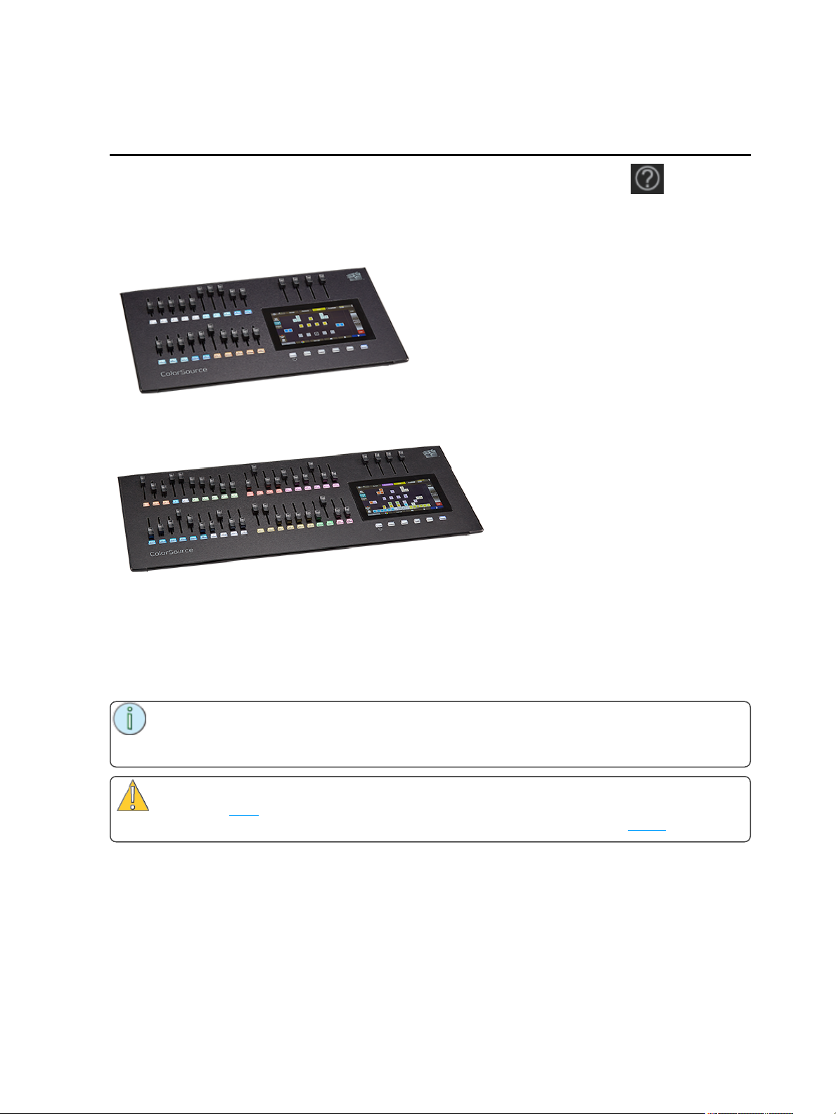
ColorSource 20
ColorSource 40
Shutdown
Hold the Stage Map button (left-most button below the screen) for three seconds to select the Shutdown
screen.
Shutdown sends the console into hibernation mode and turns off the screen and indicators.
To awaken the console, press the now blue Stage Map button again.
Note: When in hibernation mode, the console and its external power supply unit still consume
some power. To ensure zero power consumption, the external power supply should be disconnected from the AC mains supply.
Caution: All data is stored internally in non-volatile memory. Do not switch off the power until
any pending save operation is completed, or you may lose data. It is strongly advised that you
make periodic backups of important data to an external memory stick using the export function.
It is recommended to power the unit on and off on the AC side of the external power supply.
Welcome to the ColorSource Help System 7
Page 8

8 Welcome to the ColorSource Help System
Page 9
ColorSource Overview
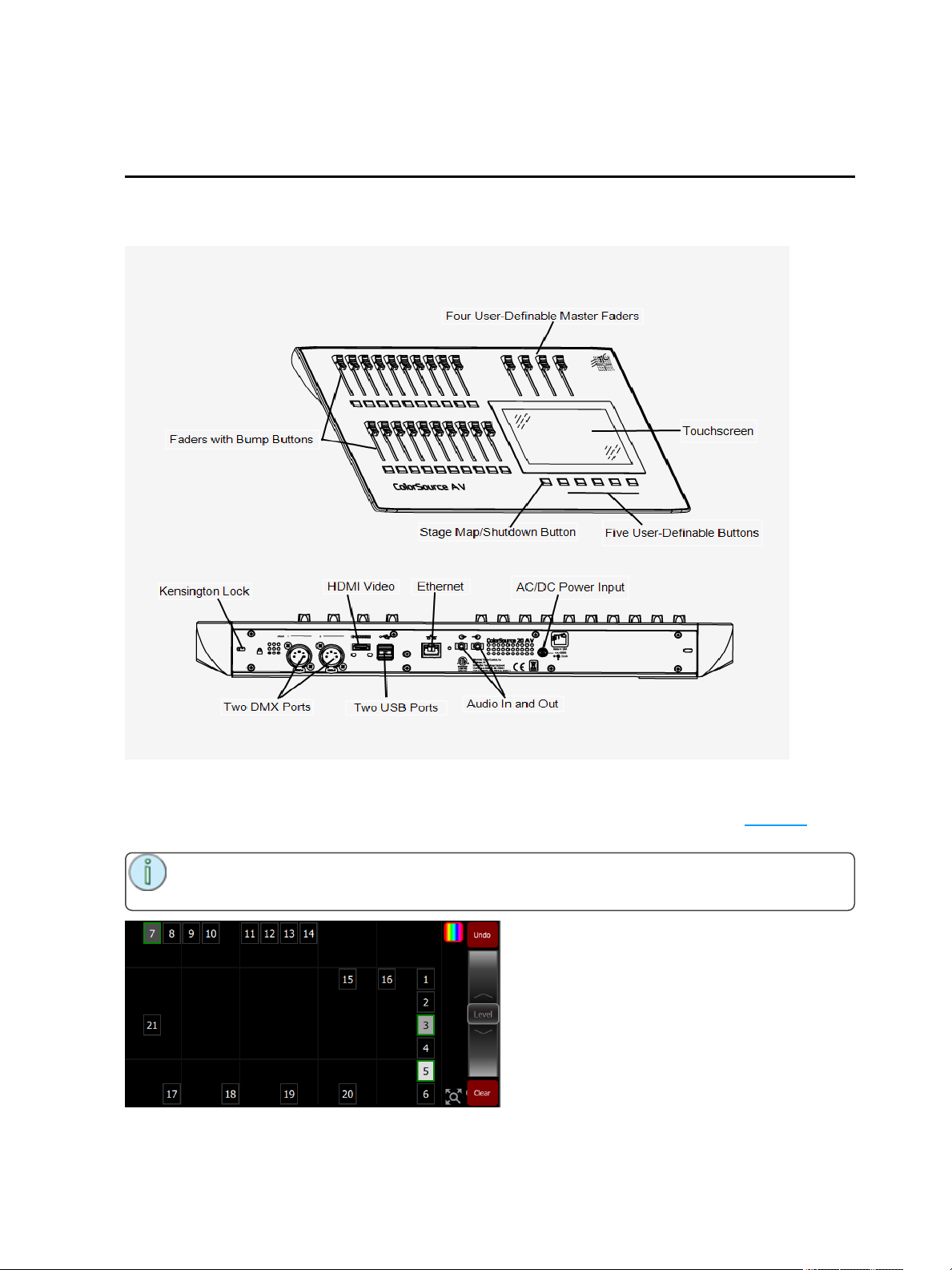
The ColorSource console is made up of four different physical areas; the touchscreen (stage map), the
faders and bumps, the crossfader, and the master faders. It is important to familiarize yourself with these
different areas as you learn to use your console.
Stage Map
The Stage Map button (left-most button below the screen) displays a topographical map of channels full-
screen at maximum size. You may select channels on the topographical stage map for control.
Note: The Stage Map button will toggle between displaying the Stage Map or the previously
selected display.
ColorSource Overview 9
Page 10
Available Controls
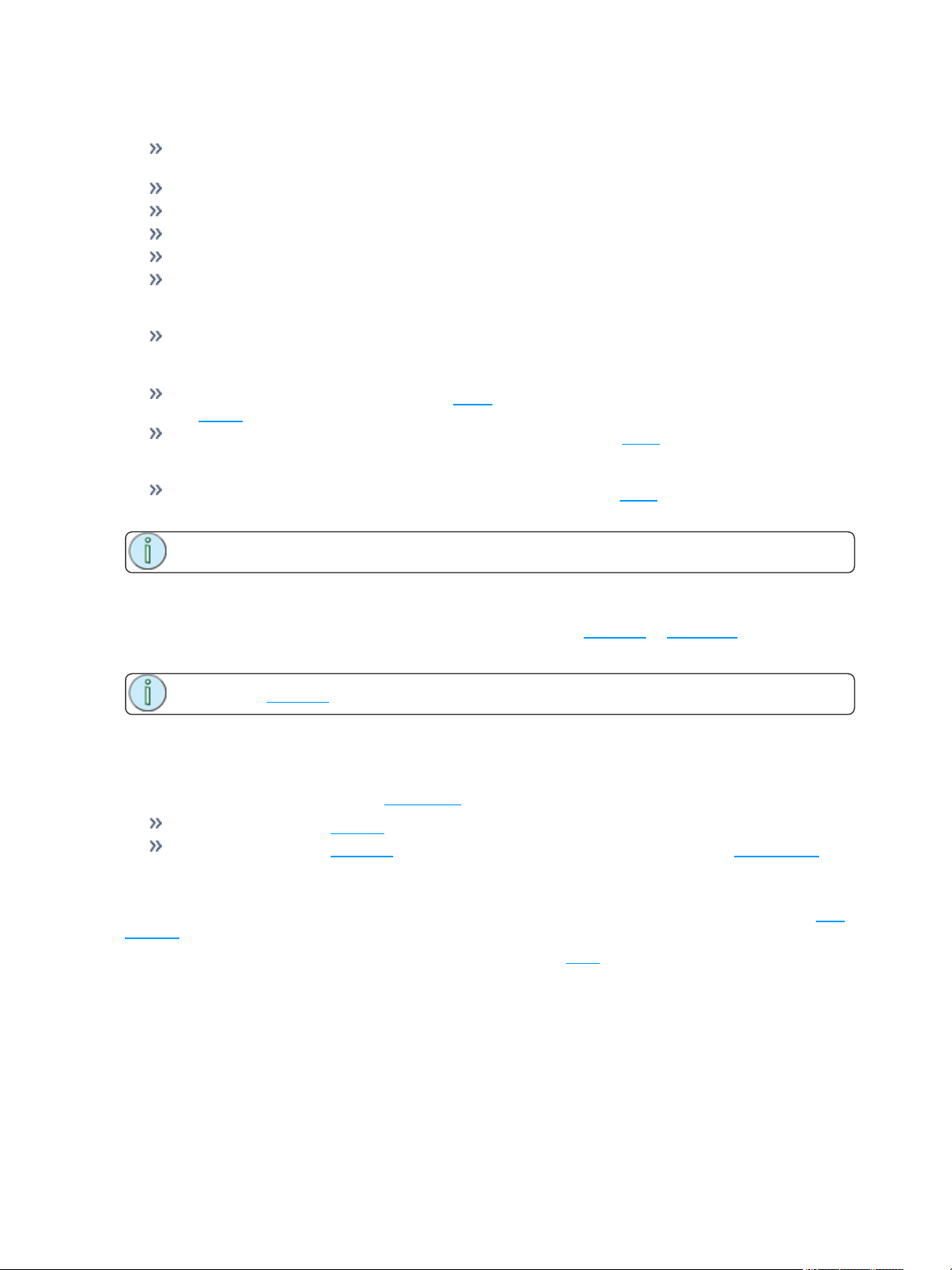
Pinch two fingers to zoom the display in or out. Zoom in to see intensity levels within the channel
cells.
Drag with two fingers to pan the display.
Single click on a deselected light to select it.
Single click on a selected light to deselect it.
Double click on a light to select that light alone and de-select all others.
Press and hold a cell to open the arrangement screen. When in arrangement mode the screen dis-
plays as a grid. Pick lights to move them to another position on the grid.
Press the Stage Map button (left-most button below the screen) to exit the arrangement mode.
Selected lights are indicated surrounded by a green box.
The vertical strip to the right of the main area displays special content that is playing:
Effects: press an icon to Stop or Edit the effect from playback. Press the icon to place the effect on
the wheel controller to increase or reduce the effect.
Audio (ColorSource AV only): press an icon to Stop or Edit the audio from playback. Pick the
icon to place the audio volume on the wheel controller to increase or reduce the volume of that audio
clip.
Video (ColorSource AV only): press an icon to Stop or Edit the video from playback. Pick the icon
to place the video luminance on the wheel controller to increase or reduce the video brightness.
Note: The Effects, Audio, and Video icons will only display if that type of content is playing.
Fader Mode
The faders to the left of the display may be set to operate individual channels or playbacks.
Two pages of channels are provided and ten pages of playbacks.
Note: See channels for information on faders and captured channels.
Bumps
The buttons below the faders are bump buttons.
Their operation changes based on the fader mode.
When the faders are in channel mode, the bumps can be used to select or deselect channels.
When the faders are in playback mode, their behavior is set based on the selected button mode.
Crossfader
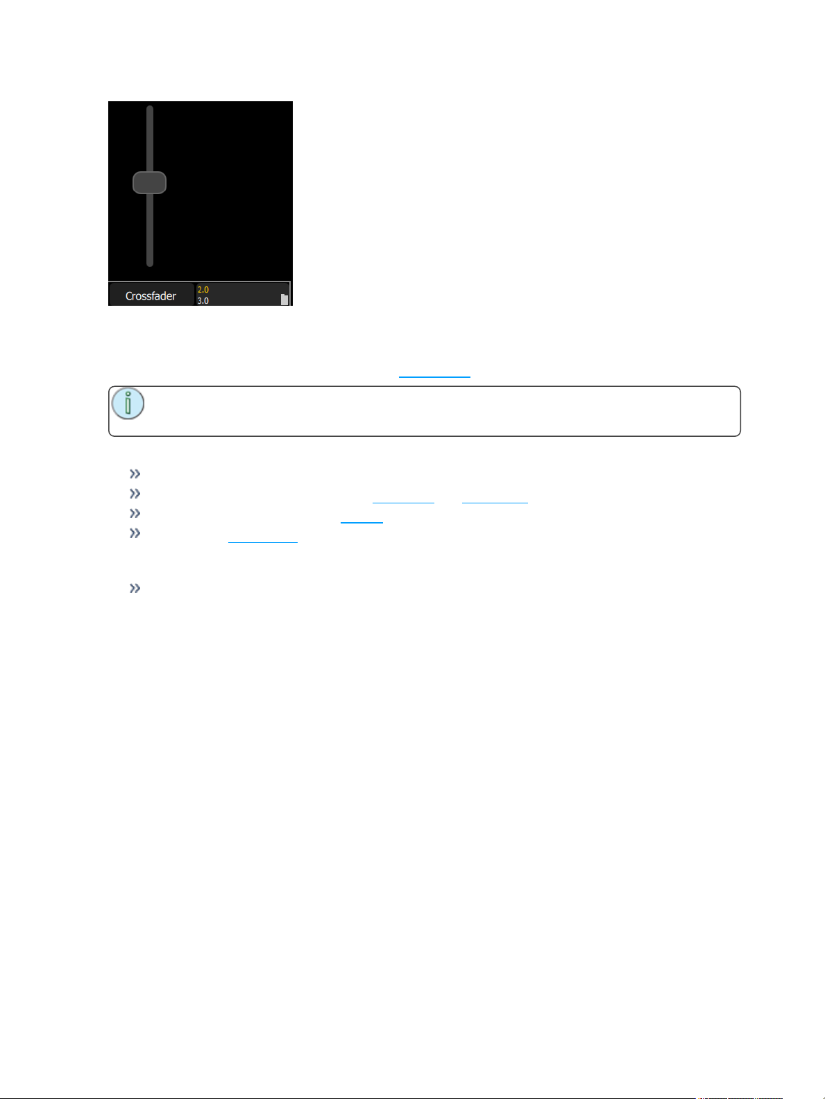
The Crossfader can be assigned to one of the four faders above the touchscreen. It is assigned in the Con-
sole tab in Settings.
The Crossfader provides manual control over the fades between cues. You can see the progress of the
crossfade and which cues are affected in the cue viewer.
10 ColorSource Overview
Page 11
Master Faders
Master faders can be used to control the output of certain functions. Master faders are the four faders
above the touchscreen. They are assigned in the Console tab in Settings.
Note: When the Playbacks or Cues faders are fully down no output will be produced by those
sections.
Master faders default to these functions:
Volume (ColorSource AVonly: controls the audio volume.
Playbacks: controls the output of the playbacks and sequences.
Cues: controls the output of the cue list.
Crossfader: Crossfades the cue list from the Live to the Next step.
In Simple Mode
Masters 1- 4: The four playback masters. You may record the output and store it on one of the four
masters to be re-used later.
ColorSource Overview 11
Page 12

12 ColorSource Overview
Page 13
Getting Started With Patching
To be able to control the lighting fixtures in your system you need to assign each fixture (or a group of dimmers) to a channel fader. The channel fader can then be used to set intensity of a fixture. The channel also
becomes a way to select that fixture for other types of control like color changes, or adjustment of other
parameters (in the case of a moving light, for example). The fixtures in your lighting system are controlled
using the DMX protocol and each dimmer or fixture uses a DMX address (or set of addresses) to communicate with the console.
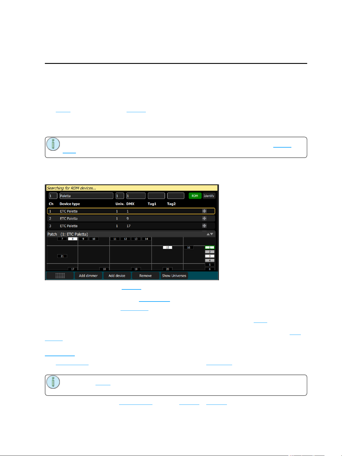
The Patch is used to associate a channel with DMX addresses and device types. Once a channel is
patched to an address or addresses, and the output is connected to a device (for example a dimmer, moving light, or accessory), the channel will then control that device.
To access the Patch functions, press the Setup > Patch.
Note: If your patch stays the same between shows, you can save time by saving a default
show, which will load your patch automatically for you.
Patch
Displays the patching screen and controls.
Patching associates a console channel number with an address or block of addresses on the DMX output.
You must ensure that the address on the light, dimmer, or device matches the address that you setup in
Patch. To patch a basic device, press Add Dimmer.
Complex devices with several parameters, such as motion, color, or beam controls, are described by a per-
sonality. Select the make and type of device to match the actual connected device. Some devices have
modes that must also match on the device and in the patch list. Lighting devices with RDM available and
enabled are found automatically and added to the list of devices. You must still assign them to console
channel numbers though. To patch a complex device that is not automatically found by RDM, press Add
Device.
During patching you may add tags to each light, dimmer, or device to aid in convenient grouping on the
quick select screen.
The lower section of the screen may be set to display the channel stage map or a view of the DMX uni-
verses output.
Note: The media outputs, audio and video, do not need to be patched as they are controlled dir-
ectly.
The settings and patch for the independents are on the Ind. Tab in Settings.
Getting Started With Patching 13
Page 14
Add Dimmer
Dimmers are single-address devices that control intensity only. For patching multiple-address devices, see
Add Device.
Note: Dimmer patching can also be used to connect other simple devices that only require one
DMX address.
Patching a Dimmer or Single-address Device
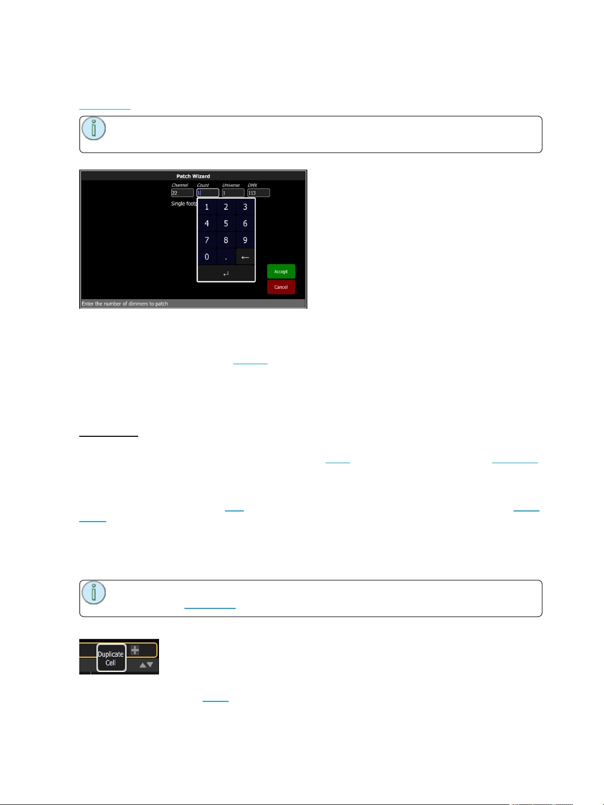
1. Press Add dimmer.This will open the Patch Wizard display.
2. Select Channel to enter the channel number.
3. Select Count to enter in the number of similar devices you are patching. If the quantity is more than
one, each dimmer will occupy one DMX address, starting from the address you specify.
4. Select DMX to enter the DMX address.
5. Select Accept to patch, or Cancel to exit.
For Example:
If you set the count to 12 and the DMX address to 20, the devices will occupy DMX addresses 20-31.
Patching places the items in a list in the upper part of the patch screen and on the topographical stage map
in the lower part of the screen in rising order starting in the top left corner. You may select one channel at a
time in the list or on the stage map.
Each channel may be edited in the boxes at the top of the screen for channel number, DMX Universe and
DMX address. You may also add tags to each item so that they may be conveniently grouped on the quick
select screen.
Duplicate Cell
Duplicate cell lets you place two dimmers on the Stage Map in different places patched to the same channel.
Note: Duplicate cell adds dimmers only and not devices. Devices must be patched and placed
individually. See Add Device.
Pick a channel in the patch list and select the + button and then the Duplicate cell button to make a copy.
A new cell is added and is patched to the next-highest free DMX address. You may change the address
and universe and set tags in Patch.
14 Getting Started With Patching
Page 15
When a duplicate cell is selected or operated, each of the duplicate cells on the Stage Map will respond
together. Each cell of a duplicate channel may be moved separately on the Stage Map.
Note: : You can also add dimmers to a channel without showing them as separate cells on the
Stage Map. Use Add Dimmer and then set the channel number to be the same as the channel you
want to add the dimmer to. Dimmers added in this way do not consume space on the Stage Map,
for instance you may need one channel to control a range of dimmers for house lights without wishing them to be each placed and indicated separately.
Add Device
Devices are multiple-address lights with a number of controllable parameters, such as position, color,
beam, and intensity. Devices have their own personality, which defines what each parameter does and
which controls are needed.
Note: Lighting devices with RDM available and enabled will be found automatically and added
to the list of devices in the patch. However, you must assign them to console channel numbers.
Patching a Device
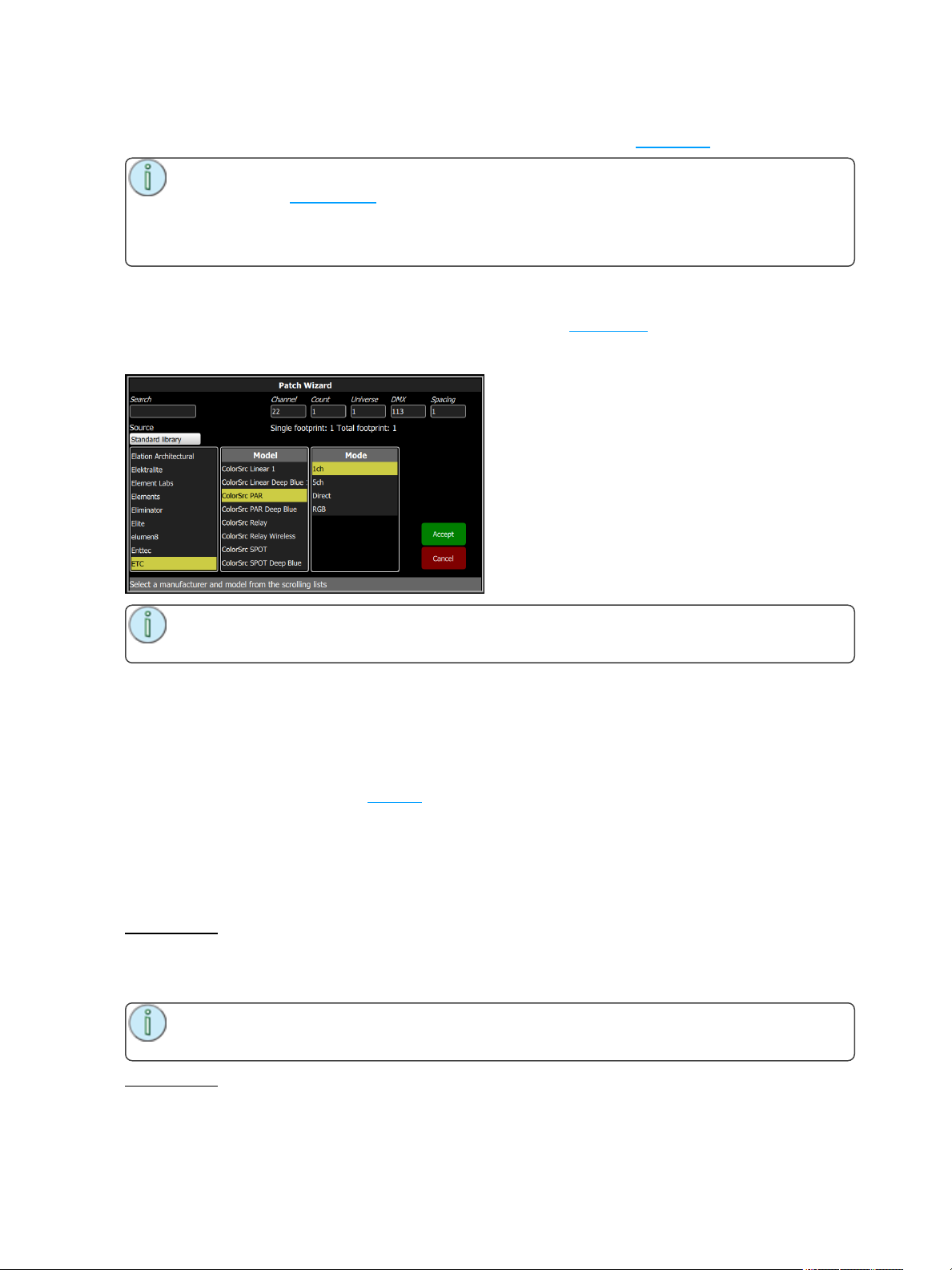
1. Press Add Device. This will open the Patch Wizard display.
2. Select the correct personality from the list provided. Select the make and type of device to match
the actual connected device. Some devices have modes that must also match on the device and in
the patch list.
3. Select Channel to enter the channel number.
4. Select Count to enter in the number of similar devices you are patching. If the quantity is more than
one, each device will occupy the number of DMX addresses used by its footprint, starting from the
address you specify.
5. Select DMX to enter the starting DMX address.
6. Select Accept to patch, or Cancel to exit.
For Example:
If you patch 12 devices with a footprint of 6 DMX addresses each to address 20, they will occupy DMX
addresses 20 - 91.
To patch devices with a gap between them, adjust the Spacing value to a larger number.
Note: Do not adjust this to a smaller number as that will cause overlaps and unexpected beha-
vior from your devices.
For Example:
Getting Started With Patching 15
Page 16
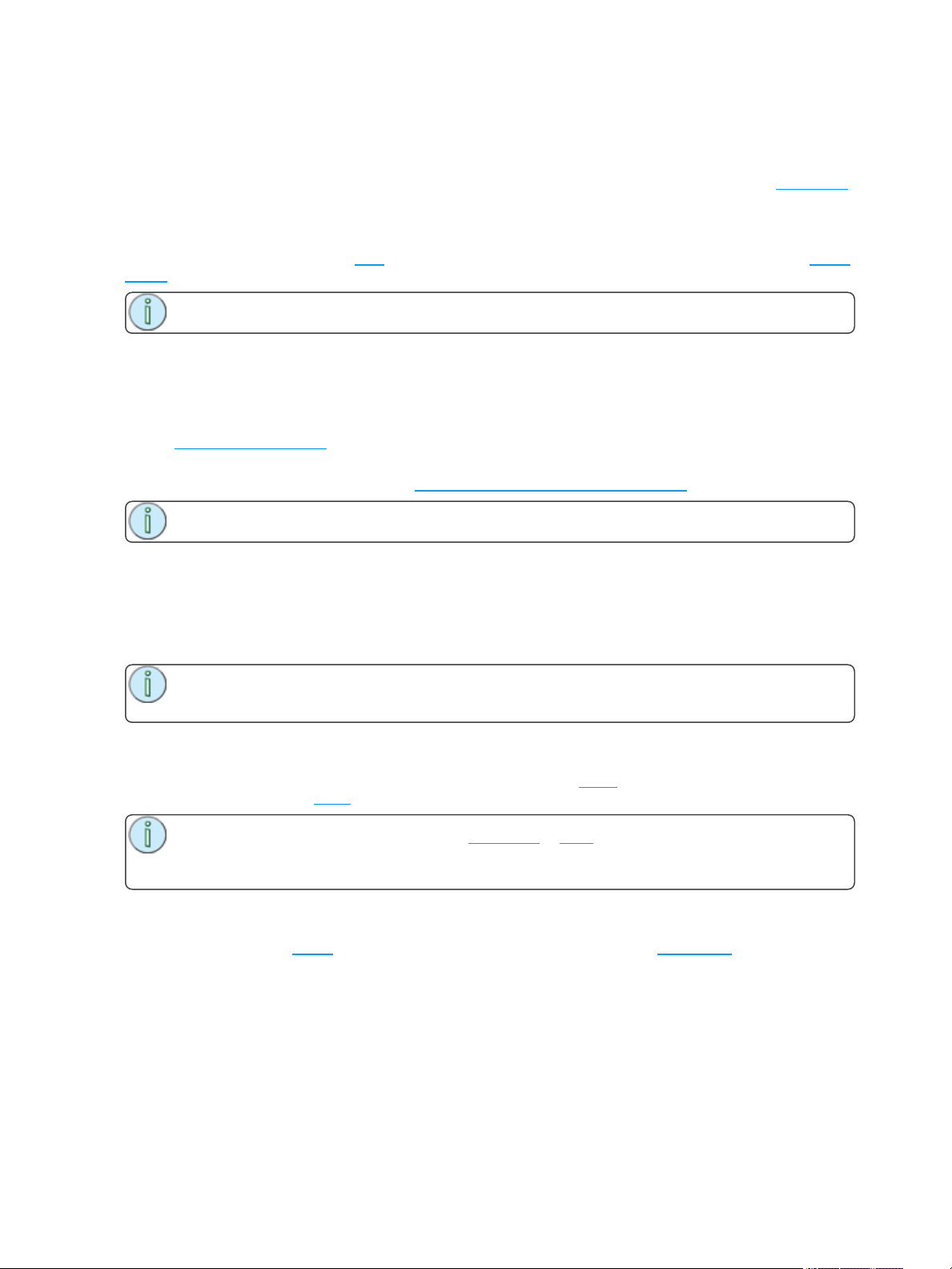
Your devices use 17 channels, but you would prefer to manually address them at logical starting nubmers
like 1, 21, 41 and so on. Use the Spacing cell to change the footprint to 20 so that those devices will automatically patch at 1, 21, 41...
Patching places the items in a list in the upper part of the patch screen and on the topographical stage map
in the lower part of the screen in rising order starting in the top left corner. You may select one channel at a
time in the list or on the stage map.
Each channel may be edited in the boxes at the top of the screen for channel number, DMX Universe and
DMX address. You may also add tags to each item so that they may be conveniently grouped on the quick
select screen.
Note: Custom fixture profiles can be loaded onto the console.
Loading a Fixture Profile
If you have devices in your lighting system that cannot be discovered by RDM and are not included in the
onboard device library, you can create your own personality for that device and import it into your show file.
There is a device editor application for Windows PCs called ColorSource Edit, which is available for download at www.etcconnect.com.
To request a fixture personality from ETC, please send your request along with the user manual, the
required mode(s) and your need by date to [email protected].
Note: For the console to recognize the profile, the file name has to be userlib.jlib.
1. You will need to save the file onto the root directory of a USB drive to be able to read it from the console.
2. With the USB drive plugged into the console, go to Setup>Patch>Add Device.
3. From the Source dropdown, select User Library. A new library will display with your fixture listed by
its manufacturer’s name.
Note: Custom device libraries are not stored on the ColorSource console itself. Please store
these custom files on your USB drive or on another computer for safe keeping.
Remove
Select a device or dimmer, and press Remove to remove from the patch. If you accidently remove a device
or dimmer, you can use the Undo function to restore it.
Note: If you have recorded a device into playbacks or cues, and then remove it from the patch,
all the recorded values will remain in the playback or cue, but they will no longer be connected to a
device.
Show Universes / Show Stage Map
The lower section of the Patch screen may be set to display the topographical Stage Map or a chart of the
DMX addresses.
The DMX address chart is view-only and may not be edited. Scroll up and down to view all the addresses in
the selected Universe.
16 Getting Started With Patching
Page 17
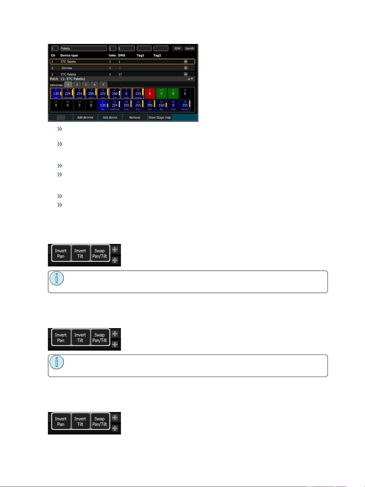
Each cell shows the DMX address, the value in the range 0-255 and the name of the parameter if for
a device patched with a personality.
Cells colored in light blue indicate the base address of the item, which is the address entered in the
Patch screen DMX box. The following cells in dark blue show the following DMX addresses used by
the device according to the size of its footprint.
Cells colored in green indicate single channel dimmers.
Cells colored in red indicate patching overlap, where more than one dimmer or device is patched to
the same DMX address. In some cases it may be desirable to patch with overlaps but usually it is a
bad idea to be avoided if possible.
Cells in black are unoccupied and not patched.
A yellow bar graph indicates the approximate value being output.
Invert Pan
Switches the pan control to run in the opposite direction. Click on the + button in patch for the device you
want to invert pan.
Note: Use this if you have rigged a light upside-down or back-to-front compared to other similar
lights so that if they are all selected together their movements will be in similar directions.
Invert Tilt
Switches the tilt control to run in the opposite direction. Click on the + button in patch for the device you
want to invert tilt.
Note: Use this if you have rigged a light upside-down or back-to-front compared to other similar
lights so that if they are all selected together their movements will be in similar directions.
Swap Pan and Tilt
Exchanges the pan and tilt channels so that pan on the console controls tilt on the device and vice-versa.
Click on the + button in patch for the device you want to swap pan and tilt.
Getting Started With Patching 17
Page 18
Note: An example of when to use this function would be if a fixture is hung sideways or a mov-
ing mirror fixture is rotated 90 or 270 degrees from other fixtures.
RDM
RDM is a two-way communications method built-in to ordinary DMX512 for lighting control. See About
RDM for more information.
The RDM button enables and disables RDM on the local DMX ports and RDM messages coming from gateways to the console. When enabled, the RDM button will be green. If you have problems with lights or dimmers connected to the local ports on the console that flicker or suffer interference when you open the patch
screen try to turn off the RDM button.
Note: When you exit the patch screen, all RDM messages are suppressed and only ordinary
DMX512 is sent to your lighting rig on the local console ports. The RDM button allows you to turn
off RDM when on the patch screen. Doing so will prevent the patch screen from finding and patching RDM lights. You should only suppress if necessary to prevent flicker or errors on the local console port(s) while you are in the patch screen.
Note: You may also choose to turn off RDM when you have patched all the lights in a rig that
you wish to use. If the rig contains lights that you do not wish to patch, they will keep appearing in
the patch list, awaiting a channel number, and you can prevent this from being an annoyance by
turning off the RDM button.
RDM via Network
RDM across a network connection from a ETC Net3 DMX/RDM Gateway to the console may be enabled
or disabled with the RDM button.
Disabling RDM at the console will not affect what Gateways do on their respective DMX outputs. RDM
activity on the DMX outputs of Gateways will depend on the type and setup of Gateway being used. To
enable or disable RDM on a particular Gateway DMX output, you should use a network management tool
such as ETC Net3 Concert, or the local controls of the Gateway itself.
Identify
Identify finds the RDM-capable lights during patching so it is easy to know which device is which when
assigning them to channels.
Note: Identify does not work with non-RDM devices or dimmers.
When RDM discovers a light, the light is placed at the top of the patch list with the channel shown as zero.
When Identify is set to On, each light selected in the patch list will identify itself exclusively, usually a light
will blink on and off. Devices that do not produce light, for example a scroller or pan/tilt yoke, may shuffle or
move. The action that a light does when told to Identify is determined by the its manufacturer.
You will need to choose a channel to patch the device.
Turn off Identify to stop all RDM Identification. Turn on Identify to see the currently selected RDM device.
About RDM
RDM is a two-way communications method built-in to ordinary DMX512 for lighting control. By using RDM,
you can find lights, find out about them and their status, patch them, and set their operating mode without
needing to go to the light itself. For lights rigged in difficult locations, RDM is very useful for remote setup.
18 Getting Started With Patching
Page 19
Discovery
RDM automatically discovers RDM-capable lights. Discovery runs continuously any time the Patch
screen is open and the RDM buttonis enabled, and will repeatedly search for devices. As devices are
added or removed from a system, they will be updated in the patch list.
Note: Discovery takes place during short periods of rest of normal DMX transmission and is a
lengthy process to complete. You should expect at least several seconds of delay to discover a
light on a small system and much longer delays on a very large system.
Addressing and Mode
RDM allows you to set the DMX address and the operating mode of a light remotely.
Setting the operating mode may change the footprint, which is the number of DMX addresses occupied by
the device. If you change the mode of a device adjacent to some other device or dimmers in patch, the new
mode could be larger than the available space and overlap already used DMX addresses. When this happens, the affected channels are indicated in the patch list in red, and you will need to take corrective action
and re-patch.
The Patch system knows how to match the chosen mode with the correct personality.
Universe
You cannot change the Universe part of the DMX patch for a Device found by RDM. RDM can only operate
on the one universe it is connected to. To change the universe a light is patched to, you must physically replug the light to another DMX cable.
Getting Started With Patching 19
Page 20

20 Getting Started With Patching
Page 21
Controlling Your Lighting System
After you have completed your patch, you are now ready to start controlling your lighting system. Your
ColorSource console gives you many options for controlling of your lights.
This section discusses how to control your channels, and how to set the parameters.
Note: Depending on the types of lights you have patched, you may have additional parameters
that you can control. Those parameters may include color, position (focus), beam, and lamp com-
mands.
Channels
A channel is the control used by the console to operate a dimmer, a group of dimmers, a dimmer and a
device, or a complete moving light fixture.
Channels need to be associated with an address in patch for there to be output.
Channel Counts
The ColorSource 20 can control up to 40 channels.
The ColorSource 40 can control up to 80 channels.
Setting the Operating Mode
Choose Simple or Complete mode on the Setup>Settings>Basic screen.
Fader Pages
Simple Mode offers one page of faders to control the first 20 or 40 channels, depending on the
model.
Complete Mode offers two pages of faders to control all the available channels, 40 or 80 depending
on the model.
Working with Dimmers / Intensity
Channels can be controlled in several different ways:
The faders, when in channel mode, can be used to control a channel's intensity.
Depending on the chosen operating mode: Complete or Simple, there are one or two pages of channels that the faders can control. In Complete Mode toggle the Channel button to access each of the
pages.
Note: The second page of channels is only available when channels have been patched
on that page (above 21 or 41, depending on the console model).
You can use the touchscreen and select channels directly on the stage map. The wheel can then be
used to assign an intensity level.
You can use the keypad to select a channel and assign an intensity level.
Channels can also be controlled by the playbacks, sequences, and cues.
Captured Channels
If a channel is at a different level than the fader position, you must move the fader to match in order to pickup the level to then move it up or down.
When a level is 'captured' in this way on a fader, it replaces the intensity coming from the cues and playbacks.
Controlling Your Lighting System 21
Page 22
To release a captured channel back to the normal output from playbacks and cues, press Clear. Operating
a playback or cue containing a channel that is captured will return that channel to normal control.
Color and other parameters may also be over-ridden on captured channels.
Controls
Controls contain all the functions for controlling lights and cues, and setting color and other parameters:
Stage Map: The 'home' view of the full topographical stage map.
Color Selector: Selection of mixable colors using a color picker or color chips.
Param: Parameter control for moving or automated lights.
Cue List: The cue display.
Playback Toy: A screen to launch lighting looks and play, or busk, live.
Keypad: Classic level control by typing numbers.
Quick Select: Selection of channels in useful blocks or sets.
Effects: Lighting effects for color, intensity, and movement.
Media: Audio, Video, Image, Video Toy, and Sound2Light controls.
Note: The options, Color Selector and Param, are only available if you have patched lights
with those capabilities.
Quick Select
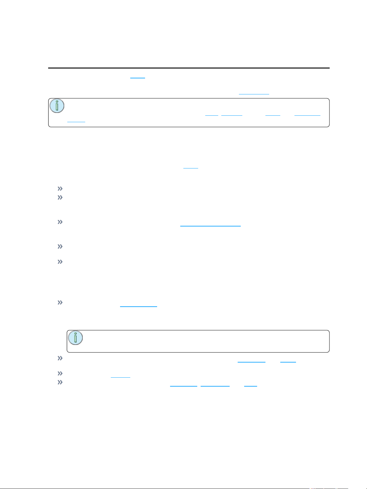
In the quick select display, you can pick groups of channels according to their position on the topographical
stage map or by choosing the tags setup during patching.
Groups display in the upper section, and the lower section of the screen displays the channel stage map.
Available groups are displayed in green boxes. Double click on a group to select only the lights in that
group, click on other groups to add or subtract channels from the selection.
While in the quick select display, the wheel operates the level of the selected channels proportionally. The
group buttons are also variable cells that may be wiped up and down to alter the value.
When you exit the quick select display, the channels will remain selected and colors or other parameters
may be applied to them.
Wheel
To the right of the stage map is the wheel. The wheel can be used to control channel levels by moving the
wheel up to increase the level or down to decrease.
The wheel can also be used to control depth of effects and sequence rate.
22 Controlling Your Lighting System
Page 23
Keypad
The keypad is opened by going to Controls>Keypad. This provides classic lighting control of channels
and levels via a numeric keypad entry.
Note: Colors, Effects, Media, and Parameter settings must be controlled on their respective
screens.
Available Buttons
+ (Plus)
- (Minus)
Thru
Full
@ (At)
..<<..(Backspace)
Enter
Keypad, Plus
Adds a channel to the selection set.
For Example:
1 Thru 10 + 20 Enter - creates a set of eleven channels: 1-10 plus 20.
Keypad, Minus
Removes a channel from the selection set.
For Example:
1 Thru 10 - 7 Enter - creates a set of nine channels: 1-6 plus 8-10.
Keypad, Thru
Selects a range of channels.
For Example:
1 Thru 10 Enter - creates a set of ten channels: 1-10.
Keypad, Full
Sets the selected channels to full intensity.
To apply the chosen intensity, you must complete the command with the Enter key.
For Example:
1 @ Full Enter - sets channel one to full intensity.
Keypad, @ (at level)
Sets the selected channels to a level specified in percent % from 0 to 100.
To apply the chosen intensity, you must complete the command with the Enter key.
For Example:
1 + 5 @ 70 Enter - sets channels one and five to 70% intensity.
Controlling Your Lighting System 23
Page 24
Keypad, << (Backspace)
The << key behaves as a backspace button for the command line.
Controlling Parameters
Depending on the types of lights you have patched, you may have additional parameters that you can control. Those parameters may include color, position (focus), beam, and lamp commands.
Color Selector
Lights that have a color mixing system may be operated from this screen. If no such lights are patched, this
option will only be available at the bottom of the stage map.
Lights must be selected before a color choice can be applied to them. Select some lights on the stage map
view, or with the bump buttons if the fader mode is set to channels, and then pick a color or try several col-
ors.
Note: Not all color mixing systems can produce precise color matches and a full range of col-
ors. It is advisable to control color on only one fixture type at a time.
For lights with fixed ranges of preset colors, such as color wheels or scrollers, use the parameter control
screen.
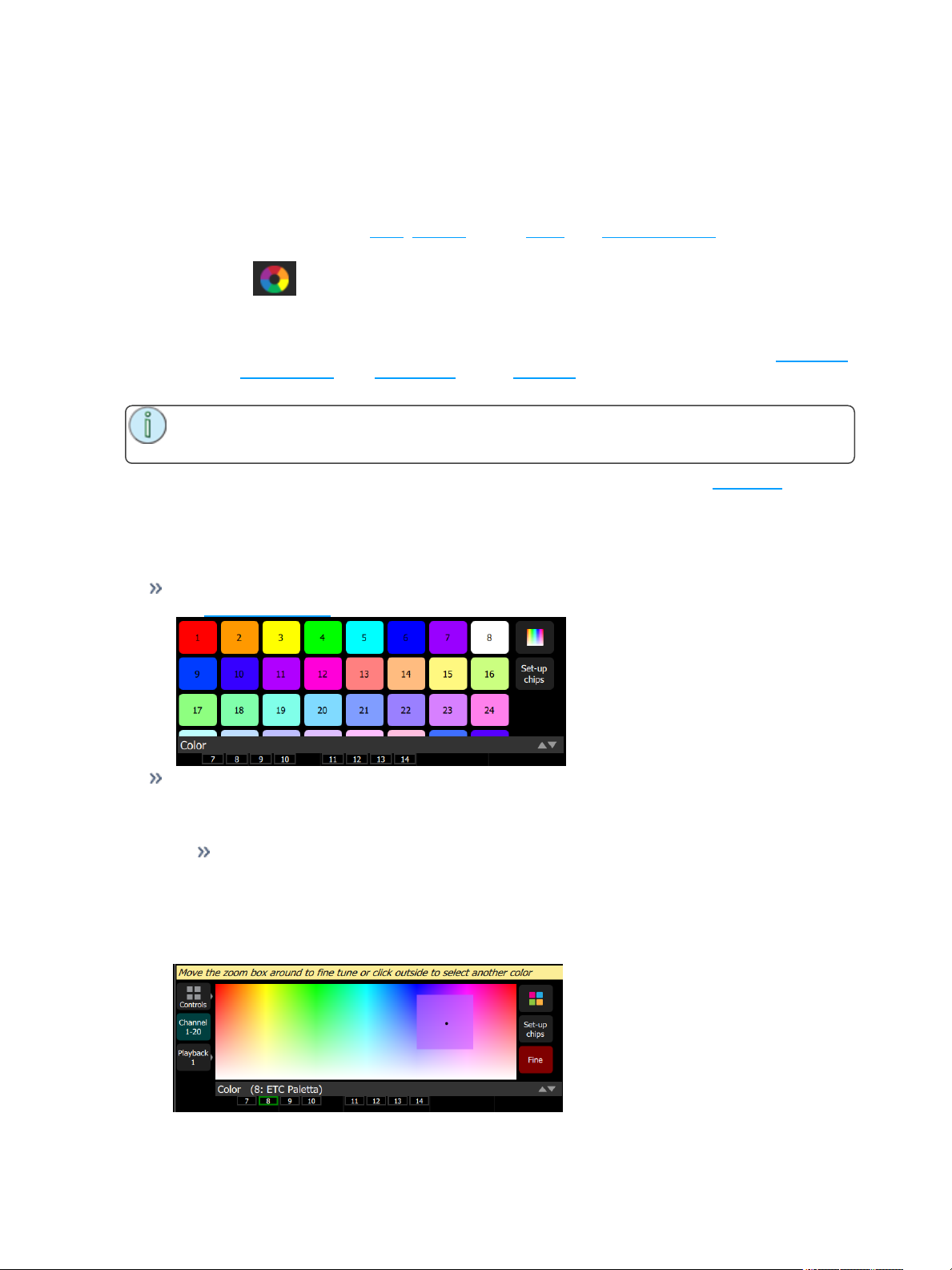
Color Controls
Two methods are provided:
Color Chips- A set of preset color chips. Color chips may be programmed to carry any color mix.
See Setup Color Chips for more information.
Color Picker- A diagram of the visible spectrum varying by hue from left to right and by saturation
(paleness) from top to bottom. A black dot is used to indicate the color selected. Press Fine to put
the color picker in fine mode. When in fine mode a box appears that may be dragged around with
finer resolution.
White- Anywhere on the bottom edge picks the color white. The actual shade of white produced will depend on the type of light and its capabilities.
Lights made by ETC that are set to 'Direct mode' will produce the color 'D50' - equivalent to a
color temperature of 5005K.
For ETC lights operating in other modes you should set the color temp close to 5005K on the
light so that they will match ETC lights running in Direct Mode. Other manufacturer's lights
may need to be adjusted separately.
24 Controlling Your Lighting System
Page 25
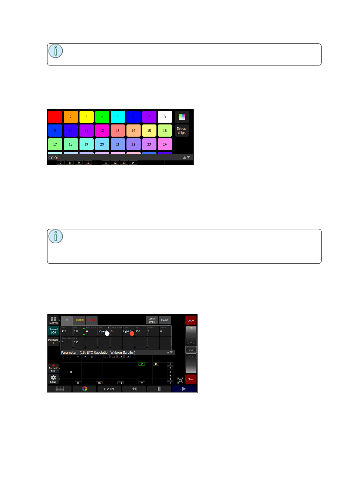
Note: Not all color mixing systems can produce precise color matches and a full range of col-
ors. It is advisable to control color on only one fixture type at a time.
You may find it necessary to pick colors independently for different lights in order that they all produce a
similar color.
Setup Color Chips
Color chips may be programmed to carry any color mix.
How to Program a Color Chip
1. Press the Setup Chip button.
2. Pick a chip to re-program.
3. Switch to the continuous color picker display, the top right button next to the color chips.
4. Pick a color, move around until you find the one you require.
5. Select Exit setup to close the function and save the new chip.
Note: Not all lights can produce all colors, and not all lights can match colors accurately, either
between similar models or with other different models.
You may find it convenient to make several similar chips for different lights in order that they all
produce a similar color.
Parameter
All the controllable features of an automated light, with the exception of the intensity and the color mixing,
are known as the parameters of the light.
Parameters may include position (pan/tilt), beam control (iris, focus, et cetera), or fixed-choice colors. The
tab along the top allows viewing of all parameters or only the position or beam parameter types.
Each cell on the parameter display is a controllable button to alter the value. Press and hold on the cell and
you can wipe the value up and down, using the entire screen height for control.
Controlling Your Lighting System 25
Page 26
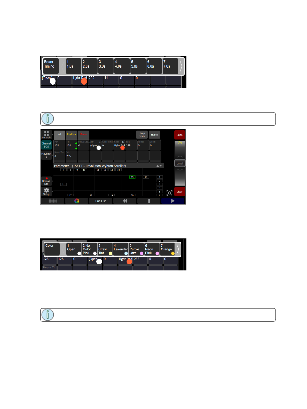
Press once and release on a cell to reveal a filmstrip-style view of the available settings, with diagrams of
gobos and samples of fixed colors. The strip may be scrolled left-right until the desired setting is found.
Pick the setting to close the filmstrip.
Parameter, All
Shows all the available parameters.
Note: The Param button is only present if you have patched lights with those capabilities.
Controls the parameters of the selected light(s). Only lights with parameters may be controlled here.
Pick a parameter and swipe the value box up and down to change values. A green arrow will appear on the
value box when you are swiping it.
Pick the value box with one press to open a filmstrip view of the available settings.
The filmstrip may be scrolled left <> right to see all the choices.
Parameter, Beam
Shows only the beam parameters. All parameters that are not position, intensity or color mixing are
included in the beam parameter set.
Note: The Param button is only present if you have patched lights with those capabilities.
26 Controlling Your Lighting System
Page 27
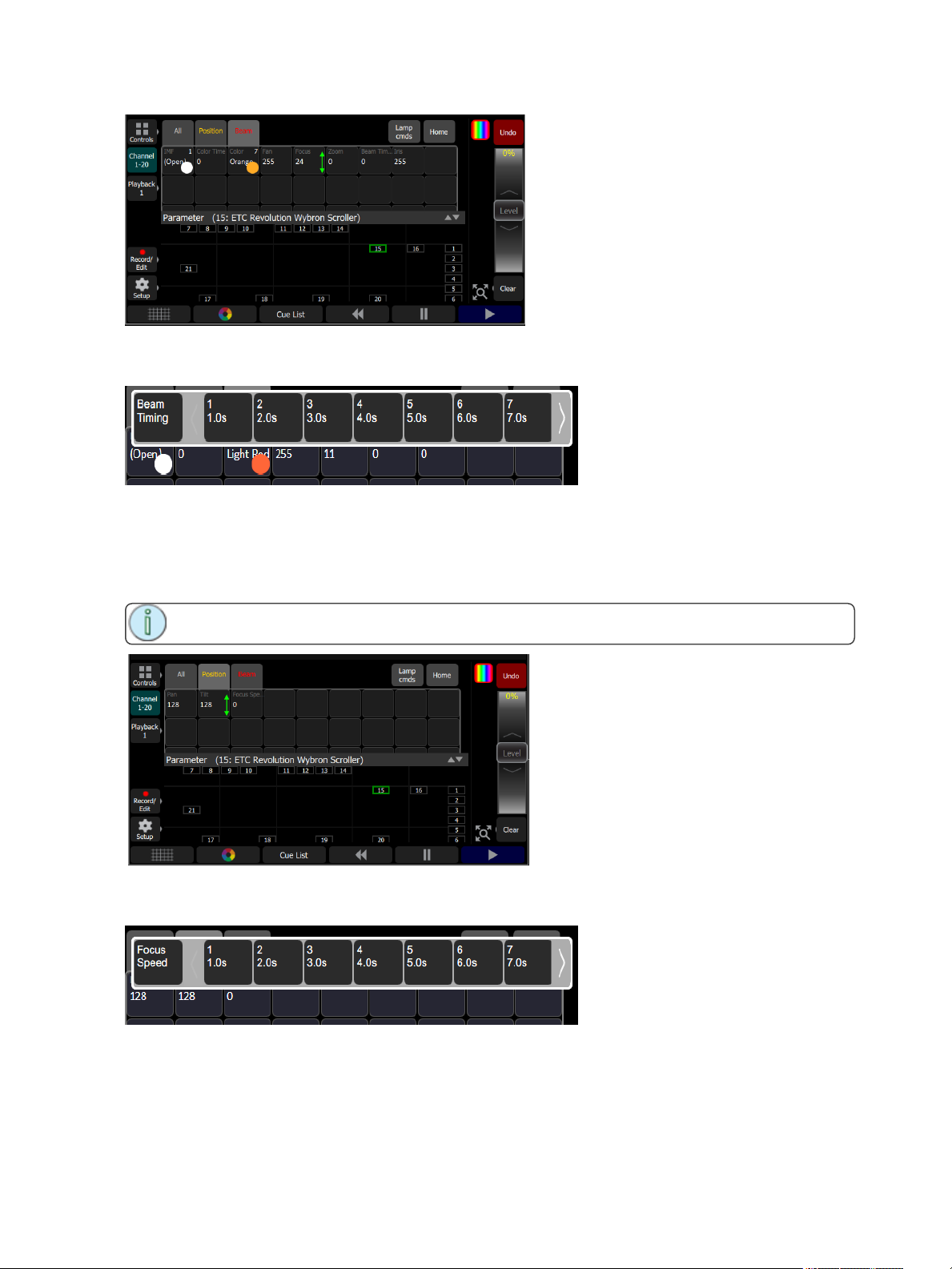
Controls the parameters of the selected light(s). Only lights with parameters may be controlled here.
Pick a parameter and wipe the value box up and down to change values.
Pick the value box with one press to open a filmstrip view of the available settings. The filmstrip may be
scrolled left <> right to see all the choices.
Parameter, Position
Show only the position parameters, pan and tilt.
Note: The Param button is only present if you have patched lights with those capabilities.
Control the parameters of the selected light(s). Only lights with parameters may be controlled here.
Pick a parameter and wipe the value box up and down to change values.
Pick the value box with one press to open a filmstrip view of the available settings. The filmstrip may be
scrolled left <> right to see all the choices.
Parameter, Lamp Commands
Click on the Lamp Cmds button to see the following options for lamp control:
Controlling Your Lighting System 27
Page 28

Lamp On: Turns on the fixture's lamp. Also known as striking the lamp.
Lamp Off: Turns off the fixture's lamp. Also known as dousing the lamp.
Reset: Resets the lamp commands.
Parameter, Home
Sends all parameters of the selected lights to their home positions. The home positions are pre-recorded in
the patching personality files, and may not be changed by the user.
Generally, parameters home to useful settings. For instance, pan and tilt will be set to mid-way values.
Gobos and beam control will be set so that the beam is unobstructed and visible.
28 Controlling Your Lighting System
Page 29
Recording Your Looks For Playback
This sections covers the multiple ways that you can record lighting looks for playing back. You can record
cues, playbacks, and sequences.
A playback memory can contain one lighting look and media.
A cue is a recorded stage look that can include channel settings for intensity and other parameters,
effects, and media.
Sequences play back on the playback faders. A sequence may contain up to 99 steps with fade and
step timing.
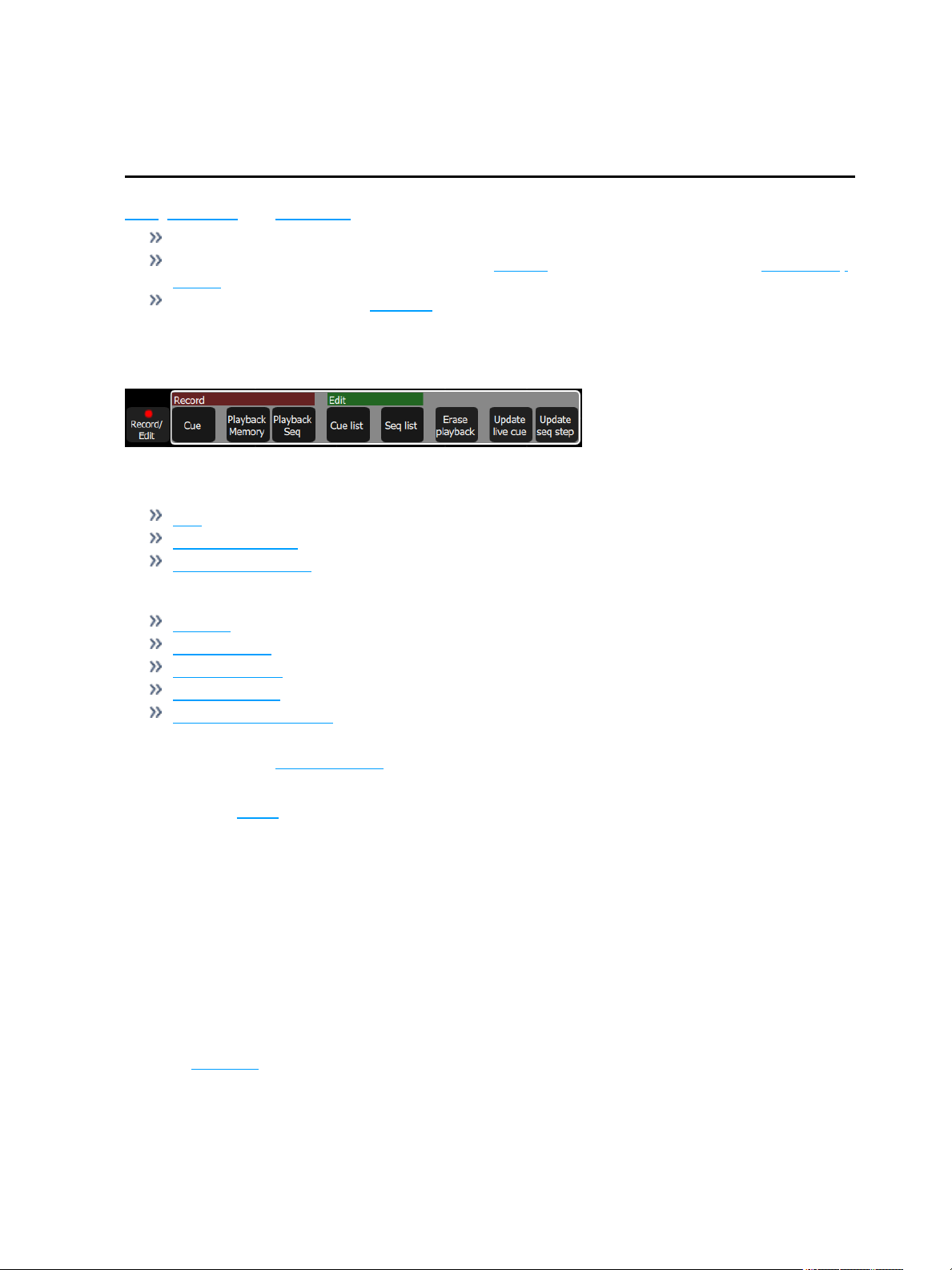
Record / Edit
All recording and editing is performed here.
The following options are available:
Record
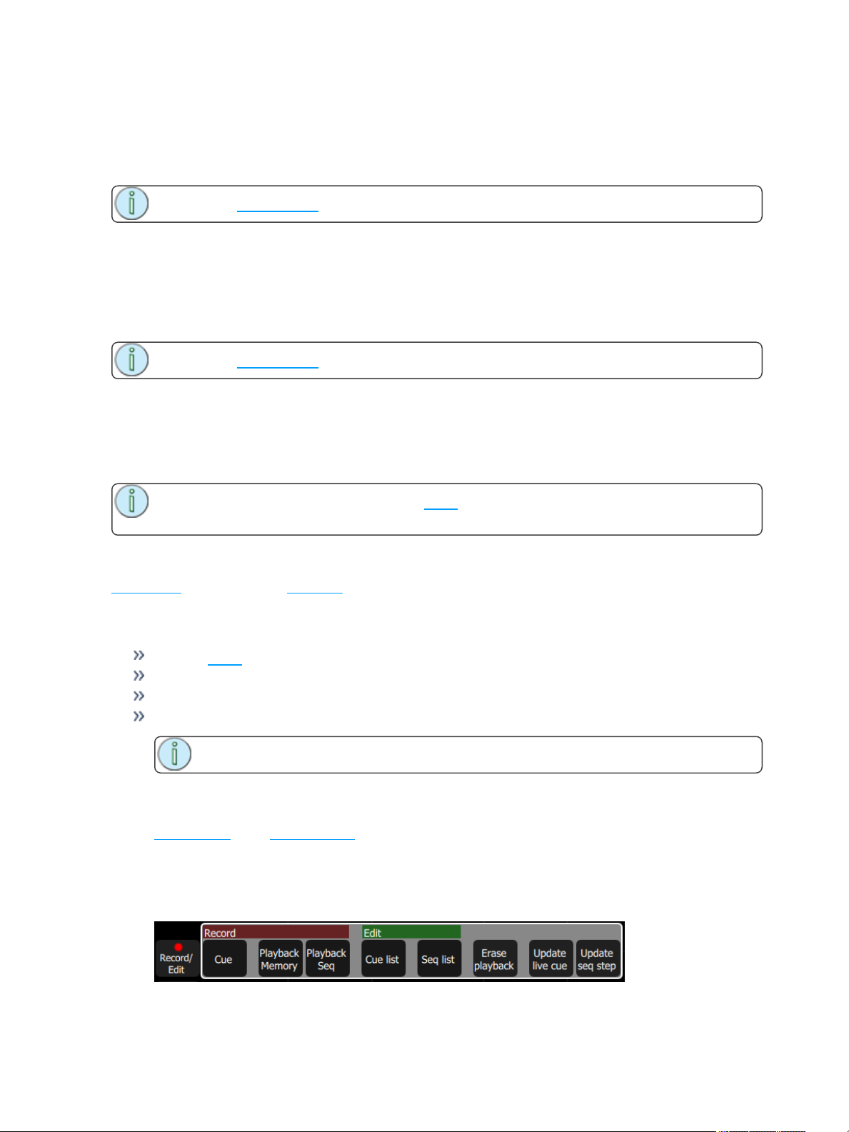
Cue
Playback Memory
Playback Sequence
Edit
Cue List
Sequence List
Erase Playback
Update live cue
Update Sequence Step (only displays when a step needs to be updated.)
Recordings are made by capturing the output being sent to the stage. You may choose which parts of the
scene to record using Include Options. If you do not specify the Include Options, only lights set to an intens-
ity above zero will be recorded.
If audio or video media is playing at the time, you will be prompted to include it in the recording.
In Simple Mode
Recordings are made by capturing the output being sent to the stage.
Pick one of the four Memory Master faders above the screen to record to.
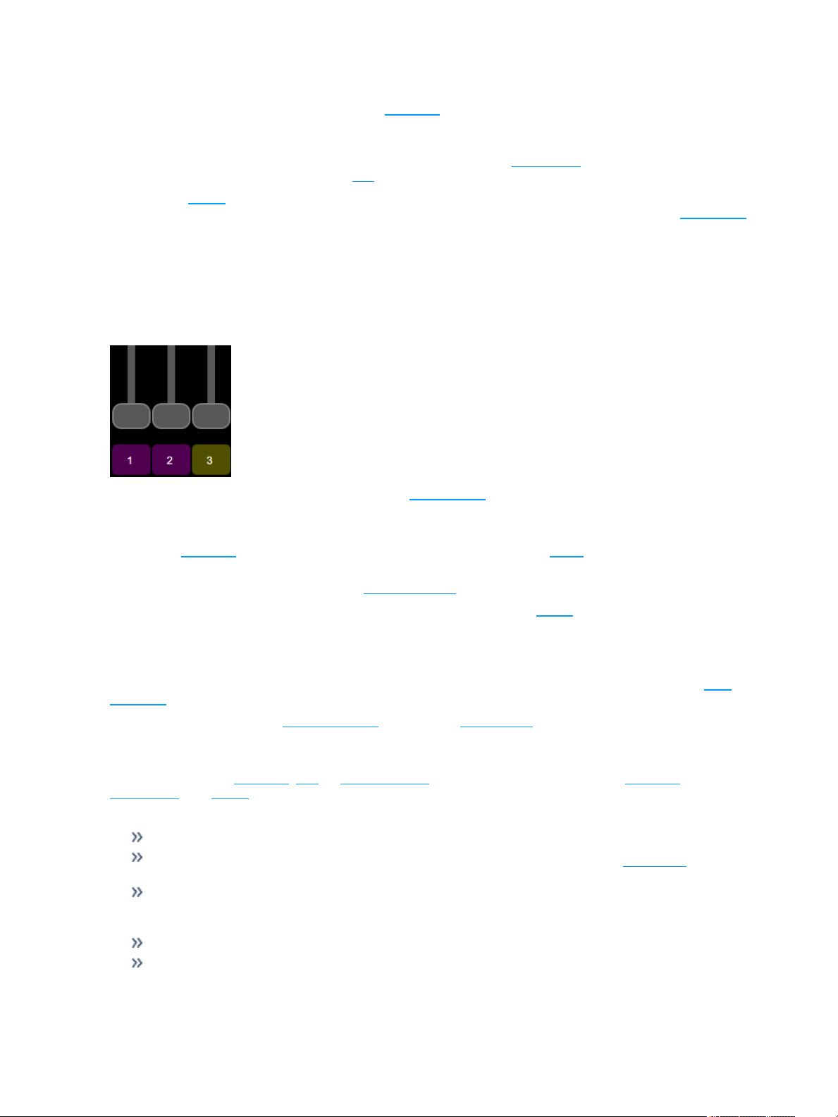
Recorded faders are indicated in Mauve color.
To edit an existing memory raise its master so that it plays on stage then make some changes using the
channel faders, the color picker, parameters or the keypad, then re-record to the same master position.
Playbacks
The faders can operate the levels of the playbacks. Playbacks can contain one lighting look, or they can
contain a sequence, which is made up of multiple lighting looks. Playbacks are mixed with Highest-Takes-
Precedence (HTP) for both intensity and color. HTP means that the highest level of all sources will be
used.
Recording Your Looks For Playback 29
Page 30
If two playbacks are up and contain the same channels with differing colors, the resulting color will be the
combination of the two. For example, if one playback has a channel set to green and another playback has
the same light set to red, when they are mixed the light will turn yellow.
When playbacks also carry parameter values for automated lights, parameters may be run up or down on a
playback fader until another playback or cue takes control of them.
There are 10 pages of playbacks. If the page is changed, playbacks that are currently up will not change
immediately to the new page and must be brought first to zero. Playback faders may also carry sequences
of up to 99 timed steps.
Page 10 is a special case. It may be used in the same way as other pages, or it can be used as a temporary
store for remote recordings. Each time a remote recording is requested, the entire output state, including
any running media, is stored as a snapshot to a playback on page ten and the snapshot counter is incremented. If more than 20 (40) recordings are made, the counter rolls round to playback #1.
Simple static playbacks are shown in mauve on the bump button, sequences are shown in yellow on the
button.
The playbacks are all controlled by the playbacks master fader.
Record Playback Memory
To record a playback, select Record Playback Memory and then pick a bump button. A playback memory
can contain one lighting look.
To record on a different page select a new Playback Page before pressing the bump.
You may choose to include any media that is currently selected on the Media screen from the pop-up
panel. To choose which lights are recorded, select Include Options and pick Selected, Active or All. The
default if you do not choose is Active; only lights currently on at a level will be recorded.
When a playback recording is complete, the playback page will revert to its previous setting.
Playbacks may be named and given a time. The names and times may be viewed and edited in the Play-
back Toy screen.
To clear a playback, use the Erase Playback button under Record/Edit.
Include Options
When recording to a playback, cue, or sequence step, you may specify which lighting channels, sets of
parameters, and media are included in the recording by pressing the Include Options button.
Channels:
Active: Only channels with an intensity above zero are included.
Selected: Only channels currently selected (surrounded by a green box on the stage map or brightly
lit on the bumps) are included.
All: All channels are included.
Include:
Intensity / Color: Only the intensity and color mixing channels are included.
Position: Only the position (pan/tilt) channels are included.
30 Recording Your Looks For Playback
Page 31
Beam: Only the beam channels are included (beam includes non-fadable colors such as wheels and
scrollers).
If any media is playing, you will have the option to include it in the recording.
Select Page
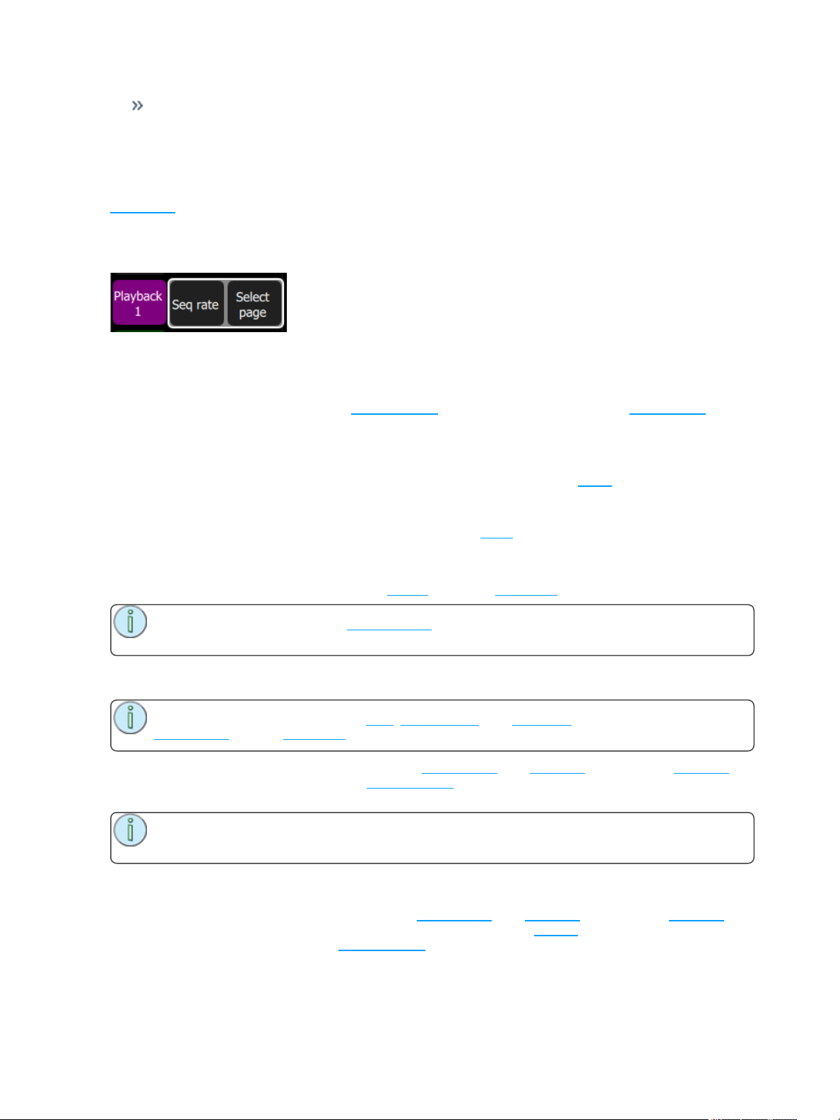
Playbacks can be arranged on 10 different pages. In normal use, all the playbacks are on the same page.
You can arrange the content of pages to match songs, scenes, or other blocks of activity in your show by
using Select Page to record playbacks to a different page. Press the Playback button to display the Select
Page button.
When the page is changed, any playback currently set to a level will remain as it is until it is taken to zero.
When a playback arrives at zero, the page will be updated for that playback. The next time the fader is
taken up, it will operate the playback on the newly selected page.
Playbacks may also be operated on the Playback Toy screen, or automatically via the Sound2Light con-
troller.
Erase Playback
To remove content from a playback, press Erase Playback and then pick the bump. You will be asked to
confirm your choice. Press Yes to clear or No to cancel. The content of the playback is not simply cleared
from the output, it is completely erased.
If you accidently delete a playback, you can immediately use Undo to bring it back.
Button Mode
The buttons below the faders may be used as bumps to operate playbacks.
Note: When the faders are in channel mode, the bump button below the fader is always used to
select the channel.
Flash
Note: The button modes; Flash, Solo, Solo Change, and Move/GO are only available when the
faders mode is set to playbacks.
When the button mode is set to Flash, pressing the bump button for a playback will cause the channels in
that playback to flash on to the level of the bumps master. The color on each channel of the selected playback will be mixed onto the output with Highest-Takes-Precedence.
Note: Operating the Flash button is the same as if the playback fader had been taken to the
same level as the bumps master.
Solo
When the button mode is set to Solo, pressing the bump button for a playback will cause the channels in
that playback to flash on and all the output from other playbacks or the cue list will be set to zero. The
intensity will be set to the level on the bumps master and the color of the selected playback will be sent to
the output.
Recording Your Looks For Playback 31
Page 32
Note: This is the same as if the playback fader had been taken to the same level as the bumps
master and all other playbacks and cues set to zero.
Solo Change
When the button mode is set to Solo Change, pressing the bump button for a playback will cause the chan-
nels in that playback to flash on depending on the intensity of each channel in the chosen playback.
If the chosen playback's channel is at an intensity above zero all the output from other playbacks or the cue
list, for that channel, will be overridden. The intensity will be set to the level of the bumps master, and the
color of the selected playback will be sent to the output, for that channel.
If the chosen playback's channel is at an intensity of zero, all the output from other playbacks or the cue
list, for that channel, will be left unaffected.
Solo Change allows parts of the scene to be replaced while other parts are left unaffected.
Move / GO
When the button mode is set to Move/GO, pressing the bump button for a playback will cause the para-
meters of the channels in the chosen playback to move to their recorded positions and values, while the
intensity remains unaffected. The intensity may be operated independently on the playback fader.
Note: Move/GO does not work with sequences.
Record Cue
Records the current state into a cue in the cue list. A cue is a recorded stage look that can include channel
settings for intensity and other parameters, effects, and media. All recording operations use the output cur-
rently live on stage. Blind recording is not permitted.
You may make a simple recording by just choosing Store. To specify a recording in more detail, select
Include options and choose the lights and parameters you wish to be included.
32 Recording Your Looks For Playback
Page 33
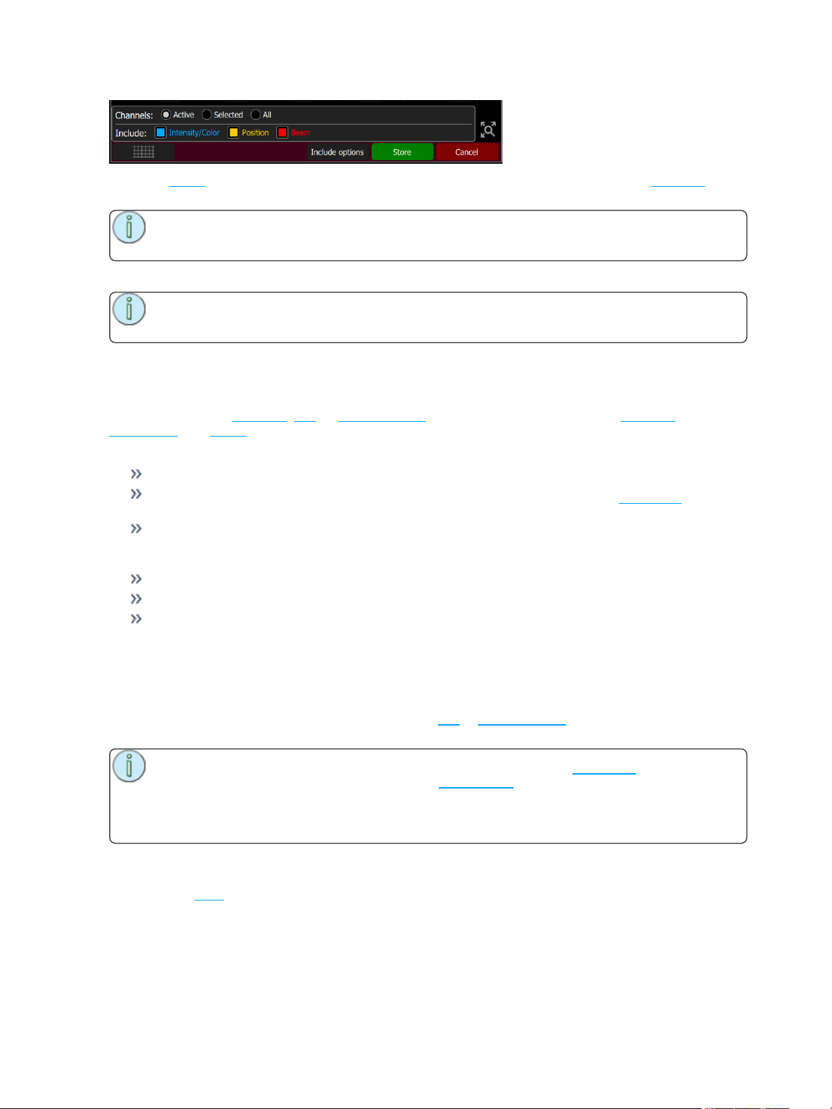
To record Media, run the media on the media screen (or from another source, for instance a playback car-
rying the desired media). You will see an option to include the running media when the cue is recorded.
Note: If you want a media clip to continue across several cues just record the same clip in each
cue. Clips repeated in consecutive cues do not re-start, they continue to run.
Each cue may be named, and its In, Out and Wait times set.
Note: The wait time commences at the start of the cue. If wait is shorter than either in or out,
the in or out will not complete before the next cue starts.
Wait time = 0 is a special case and causes the cue to wait for a manual press of the GO button.
Include Options
When recording to a playback, cue, or sequence step, you may specify which lighting channels, sets of
parameters, and media are included in the recording by pressing the Include Options button.
Channels:
Active: Only channels with an intensity above zero are included.
Selected: Only channels currently selected (surrounded by a green box on the stage map or brightly
lit on the bumps) are included.
All: All channels are included.
Include:
Intensity / Color: Only the intensity and color mixing channels are included.
Position: Only the position (pan/tilt) channels are included.
Beam: Only the beam channels are included (beam includes non-fadable colors such as wheels and
scrollers).
If any media is playing, you will have the option to include it in the recording.
Store
The current lighting levels will be stored in the selected cue or sequence step and recording will be com-
pleted. The recording mode is then closed, and normal operation resumes.
Note: Once a cue is recorded, it is placed on the live side of the cue crossfader and sent to the
output. To remove the newly made cue take the cues master down. The cues master allows cues
to be made as changes (deltas) by leaving it up and making the necessary adjustments for each
cue, or to be made as complete new states for each cue by leaving the cues master down and
making a new state for each recording.
Cue List
A list of timed cues.
Recording Your Looks For Playback 33
Page 34
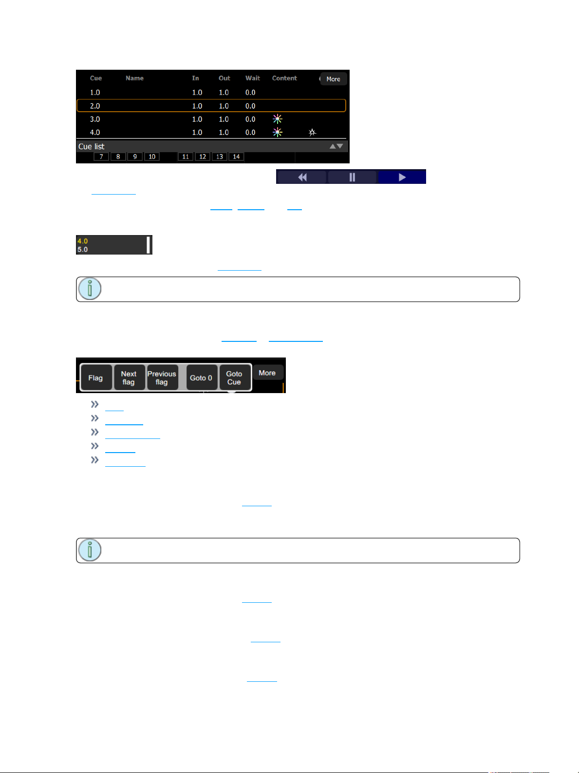
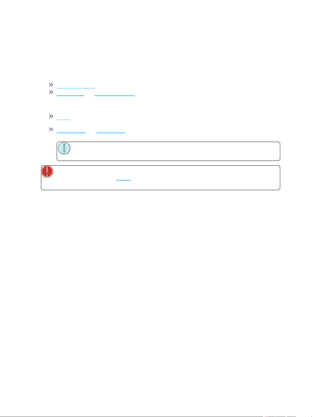
Cues are played back with the Cue Transport ( ) buttons or by moving
the crossfader up and down.
The Cue Transport buttons are Back, Pause, and GO. These buttons may be assigned to the hard buttons
below the screen, and are also always available by pressing on the cue viewer in the upper right corner.
The live and next cues are indicated on the main cue list and also on the small cue viewer (
) in the upper right corner.
Cues are played back through the cues fader.
Note: For the cues to be seen on stage, the cues fader must be up.
More
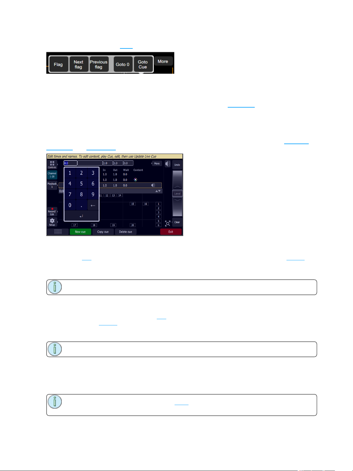
Pressing on the More button in the Cue List or Edit Cue List displays will allow access to the following
options:
Flag
Next flag
Previous flag
Goto O
Goto Cue
Flag
Cues may have a flag attached to aid in cue list navigation. Typically flags are useful to repeatedly return to
the same place in the list, for example during rehearsals.
Press Flag to place a flag on the current live cue. Press Flag again to remove a flag on the current cue.
Note: The placing and removal of a flag is a toggle action on the current live cue.
Next Flag
Advances to the next flagged cue in the cue list.
Previous Flag
Returns to the previous flagged cue in the cue list.
Goto Cue
Allows you to go to a specified cue in the cue list.
34 Recording Your Looks For Playback
Page 35
In the cue list window, press More and then Goto Cue, type in the cue number, and press Enter.
Goto 0
Cue 0 does not exist as a real cue. It is an imaginary cue before the first cue.
Press Goto 0 to take all levels from the cue list to zero, and prepare the crossfader for the first cue.
Edit Cue List
The Edit Cue List option is available by pressing the Record/Edit button and then selecting Cue List. This
opens the cue list editor for the main cue stack. Here you may change cue names and the timing of fades.
Pick the cue you want to edit in the cue list in the upper part of the display. You can also insert new cues,
copy cues, and delete cues.
New Cue
Inserts a new cue. The new cue is added to the next free whole-numbered cue at the end of the cue list.
The new cue may then be given another number, including a fractional or 'point' number.
For example, to insert a cue between cues 4 and 5, you would enter 4.5.
Note: The cue list is not re-numbered when a cue is inserted.
Copy Cue
Copies the selected cue and creates a new cue. The new cue is added to the next free whole-numbered
cue at the end of the cue list. The new cue may then be given another number, including a fractional or
'point' number.
For example, to insert a cue between cues 4 and 5, you would enter 4.5.
Note: The cue list is not re-numbered when a cue is inserted.
Delete Cue
Deletes the selected cue.
The cue list will not be re-numbered, and the missing cue will be skipped the next time the list is played.
Note: A deleted cue may be recovered if Undo is pressed immediately after the deletion is per-
formed.
Recording Your Looks For Playback 35
Page 36
Update Live Cue
Records the current state of the channels to the live cue in the cue list. The cue's previous content will be
replaced.
All recording operations use the output currently live on stage. Blind recording is not permitted.
Use Update Live Cue to quickly change or edit the cue on stage.
Clear Cues
Clears the output from the cue list. The action is the same as taking the cues fader to zero.
Note: The cue list position is not affected. Pressing GO will fade in the next cue after the one
that was cleared.
Record Sequence
Sequences play back on the playback faders. A sequence may contain up to 99 steps with fade and step
timing.
Select the bump button of the playback to which you want to record the sequence. If a sequence already
exists in that position, you may add steps to it, they will be added to the end of the existing sequence.
Each step of a sequence may contain channels, parameters, and media. To choose which channels, para-
meters, and media are recorded for each step, select Include Options.
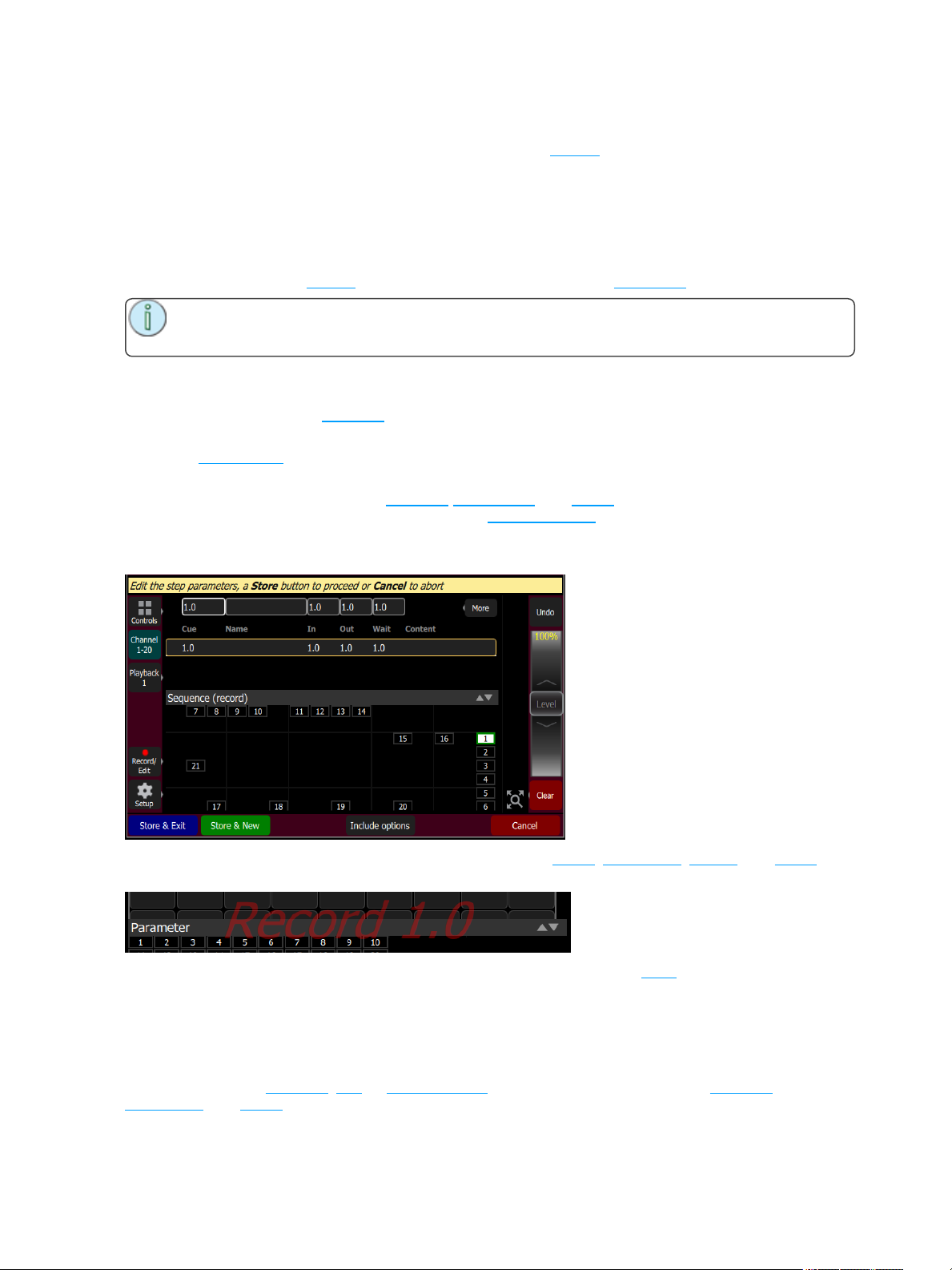
Sequence recording is a mode which takes over the screen. The recording mode is shown by a red surround to the screen.
While in the recording mode you may visit other screens to set colors, parameters ,effects, and media.
While in those screens, a red watermark will be displayed showing what step you are editing.
To return to the main recording screen press Record / Edit again. You may store the step you have made
and exit immediately with Store & Exit or you may store the step and remain inside sequence recording to
record further steps with Store & New. Press Cancel to leave the recording screen without saving any-
thing.
Include Options
When recording to a playback, cue, or sequence step, you may specify which lighting channels, sets of
parameters, and media are included in the recording by pressing the Include Options button.
36 Recording Your Looks For Playback
Page 37
Channels:
Active: Only channels with an intensity above zero are included.
Selected: Only channels currently selected (surrounded by a green box on the stage map or brightly
lit on the bumps) are included.
All: All channels are included.
Include:
Intensity / Color: Only the intensity and color mixing channels are included.
Position: Only the position (pan/tilt) channels are included.
Beam: Only the beam channels are included (beam includes non-fadable colors such as wheels and
scrollers).
If any media is playing, you will have the option to include it in the recording.
Store
The current lighting levels will be stored in the selected cue or sequence step and recording will be com-
pleted. The recording mode is then closed, and normal operation resumes.
Edit Sequence List
Opens the Sequence List editor where you can change the content of a sequence list. Press a bump to edit
a sequence.
Here you may change the content of steps, their names, and the timing of fades. Pick the step you want to
edit in the sequence list in the upper part of the display. You can also insert new steps, copy steps, and
delete steps.
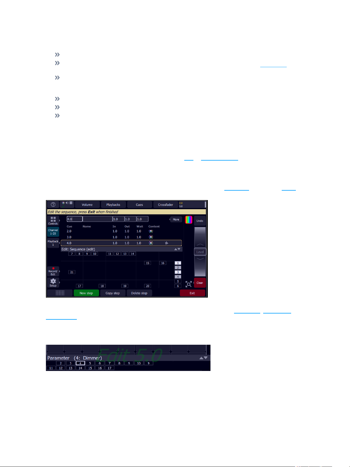
Edit Sequence List is a mode which takes over the screen. While inside the edit screen, you may visit other
screens to change colors, parameters, effects and media of the sequence you are editing. While in those
screens, a green watermark will be displayed showing what cue you are editing.
To return to the main edit screen, press Record/Edit. Press Exit to leave the editing mode. Any changes
made will be stored in the selected sequence.
Recording Your Looks For Playback 37
Page 38
New Step
Inserts a new sequence step. The new step is added to the next free whole-numbered step at the end of the
sequence list. The new step may then be given another number, including a fractional or 'point' number.
For example, to insert a step between steps 4 and 5, you would enter 4.5.
Note: The sequence list is not re-numbered when a step is inserted.
Copy Step
Copies the selected step and creates a new step. The new step is added to the next free whole-numbered
step at the end of the sequence list. The new step may then be given another number, including a fractional
or 'point' number.
For example, to insert a step between steps 4 and 5, you would enter 4.5.
Note: The sequence list is not re-numbered when a step is inserted.
Delete Step
Deletes the selected step.
The sequence list will not be re-numbered, and the missing step will be skipped the next time the list is
played.
Note: A deleted step may be recovered if Undo is pressed immediately after the deletion is per-
formed.
Update Sequence Step
Sequences play back on the playback faders. A sequence may contain up to 99 steps with fade and step
timing. Sequences must be stopped and stepped-on to the correct step for editing in order to update a step.
Operation
Select a bump for the playback you want to Stop.
Running sequences are indicated by a yellow bump button.
Stopped sequences are indicated by a blue bump button.
Stopped sequences may be advanced by pressing the blue bump button.
Note: Stopped sequences may be used as additional cue lists if required.
To Update a Sequence Step
1. Stop the sequence by using the Seq Run/Step button, which is accessed by pressing the playback
mode button in the Playback Toy display.
2. Use the bump button to advance to the step you wish to edit.
3. Then you may alter the lighting, effects, and media as required.
4. When the edit is complete, select Update Seq Step to save the changes. Update Seq Step will display only when a step needs updating.
38 Recording Your Looks For Playback
Page 39
5. Pick the bump of the sequence to be updated to complete the update.
Note: There may be several stopped sequences at any given time.
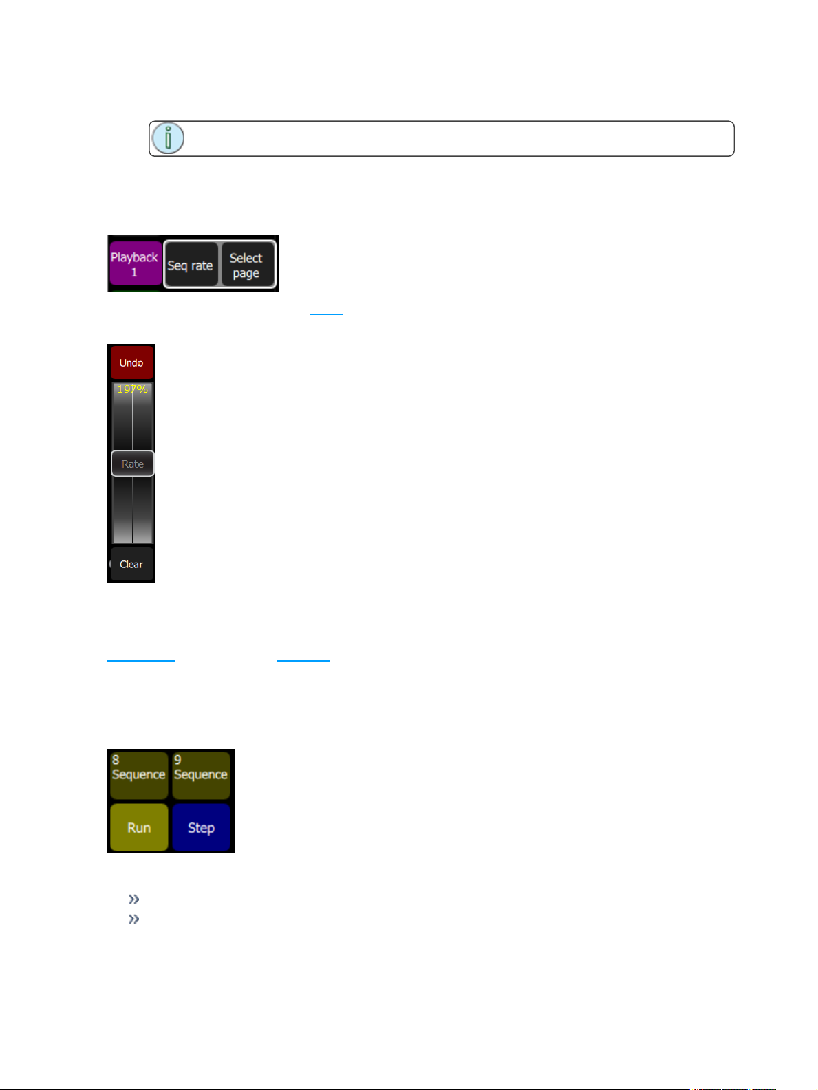
Sequence Rate
Sequences play back on the playback faders. A sequence may contain up to 99 steps with fade and step
timing.
Press Seq Rate and then select a bump for the playback you want to rate control.
The wheel will change to indicate rate control and the percentage of the rate will be shown on the wheel.
Sequence rate may also be viewed and altered on the playbacks page.
Sequence Run / Step Control
Sequences play back on the playback faders. A sequence may contain up to 99 steps with fade and step
timing.
The Sequence Run/Step button is located in the Playback Toy display. A Sequence Run/Step button will
display below each sequence and will only control that particular sequence. The button is a toggle that
either lets you stop a sequence so you can manually go through the steps by pressing the bump button, or it
runs through the steps automatically.
Operation
Select a bump for the playback you want to stop or start.
Running sequences are indicated by a yellow bump button.
Recording Your Looks For Playback 39
Page 40
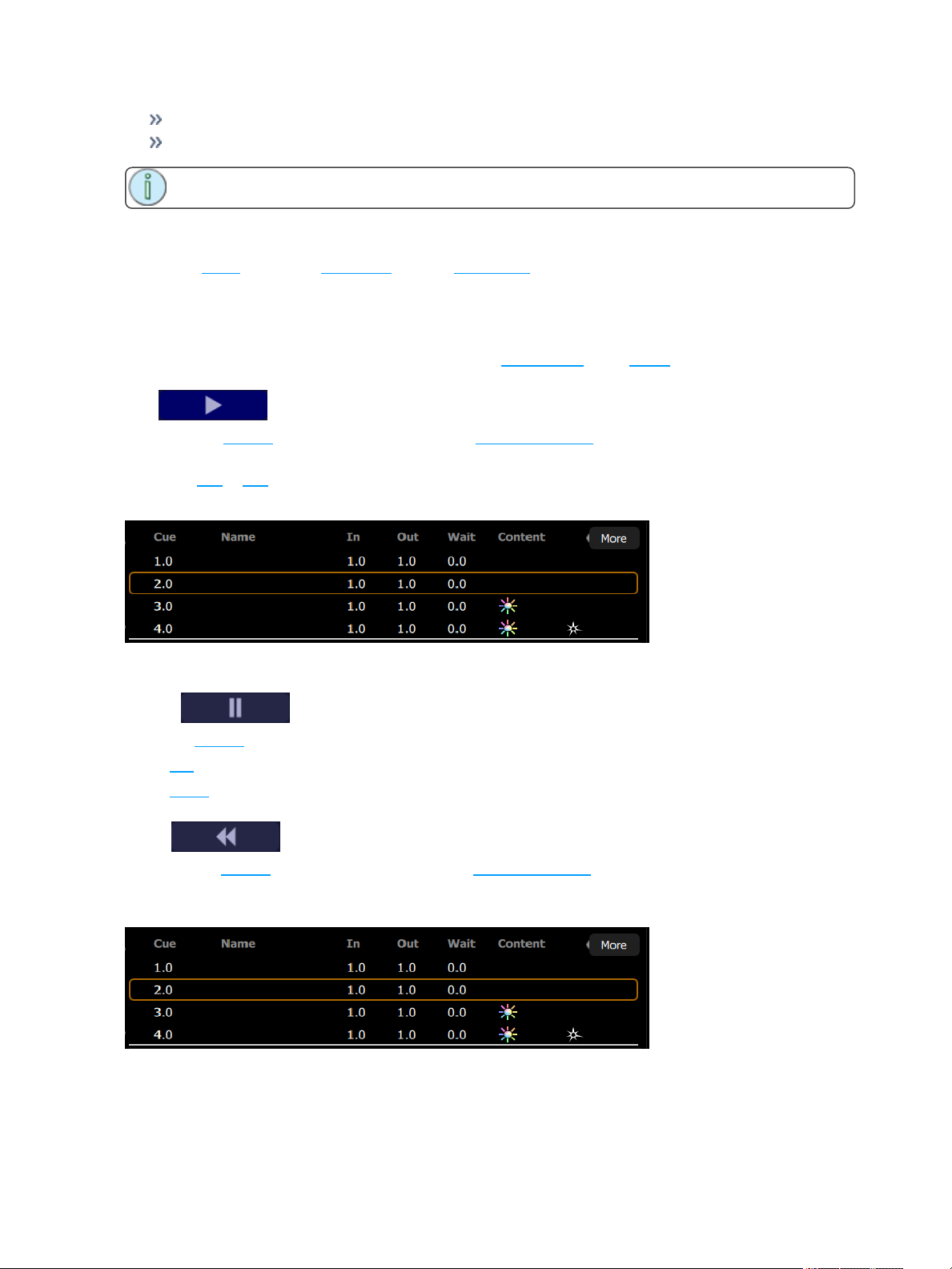
Stopped sequences are indicated by a blue bump button.
Stopped sequences may be advanced by pressing the blue bump button.
Note: Stopped sequences may be used as additional cue lists if required.
Tap Tempo
Places the bump buttons for playbacks carrying sequences into 'Tap' mode.
Hold Tap and press the bump of a playback carrying a sequence (shown in yellow on the bump) in the
rhythm you want for the sequence rate.
Press several times until the rate is correct.
Tap can be assigned to a bottom button by going to the Console tab under Setup.
GO
Advances the cue list to the next position using the default cue times.
The next position may be the following entry in the cue list, or it may be somewhere else if you are jumping
to another cue or flag.
The live cue is displayed surrounded by a yellow box with the next cue beneath it.
Press GO twice or more to rapidly advance to further cues.
Pause
Stops the cue list at its current position. Any fades that are underway will be stopped.
Press GO to resume crossfading and running times.
Press Back to return to the previous cue.
Back
Reverses the cue list to the previous cue using the default cue times.
The live cue is displayed surrounded by a yellow box with the next cue beneath it and the previous cue
above it.
Press Back twice or more to rapidly return to previous cues.
40 Recording Your Looks For Playback
Page 41
Undo
You may Undo the most recent function that changed your show data. Undo is one level only, back to the
most recent action.
The Undo function toggles between Undo and Redo so you may flip back and forth between two recorded
items to see which one is correct before moving on.
The following actions are Undo-able:
Record Playback: Undo returns the previous recording for that playback
Record Cue and Record Sequence: Undo returns the previous set of cues/steps made prior to the
most recent session. If several steps were recorded in one session, using Store and Next and not
leaving the sequence recording screen, Undo will restore all of them. If only one step was recorded
and recording was terminated with Store and Exit, then Undo will restore only that one step.
Patch: Undo will remove all changes made since opening the patch display. If several devices were
patched or altered in patch, they will all be restored to their former settings and values.
Edit Cue List and Edit Seq List: Undo restores the previous cue list contents prior to the editing ses-
sion.
Note: Undo does not work inside Edit Cue or Seq List, only once exited can Undo
restore the previous list.
Warning: Undo cannot recover all the actions you perform that might alter your show. In par-
ticular, Undo will not undo Erase functions that remove multiple items, for instance Erase Cue
List. It is strongly recommended to make frequent backups of important show data.
Recording Your Looks For Playback 41
Page 42

42 Recording Your Looks For Playback
Page 43
Using Effects
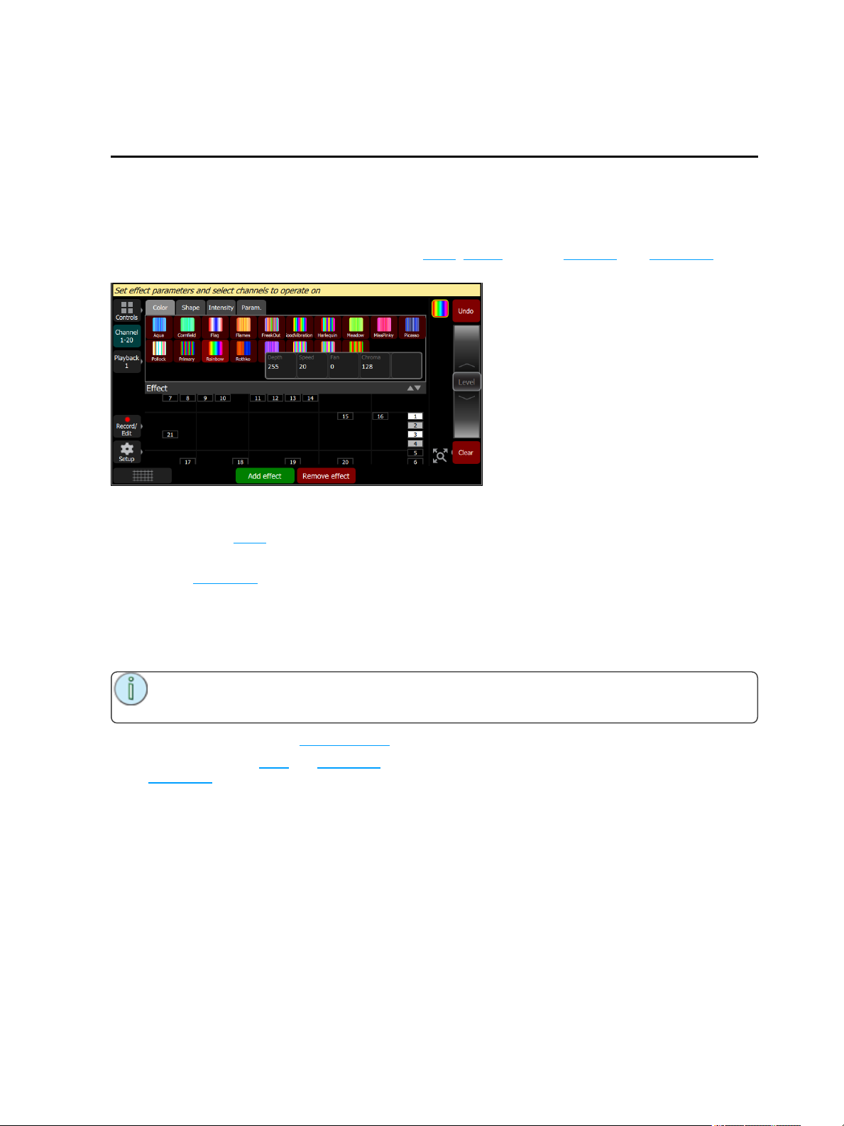
Effects are a method within ColorSource to provide dynamic, repetitive patterns to channels.
Effects
The Effects system is used to apply patterns to selected lights.
Patterns are provided for the following effect types: Color, Shape (motion), Intensity, and Parameter
effects.
How to Apply an Effect
1. Select some lights.
2. Go to Controls>Effects
3. Press Add Effect.
4. Choose an effect type from the tab area.
5. Select a pattern.
6. Adjust the effect settings for the desired result. The available effect settings change based on the
effect type selected.
Note: The order in which lights are selected is relevant and will affect the behavior of the fan set-
ting.
To remove an effect, press the Remove effect button.
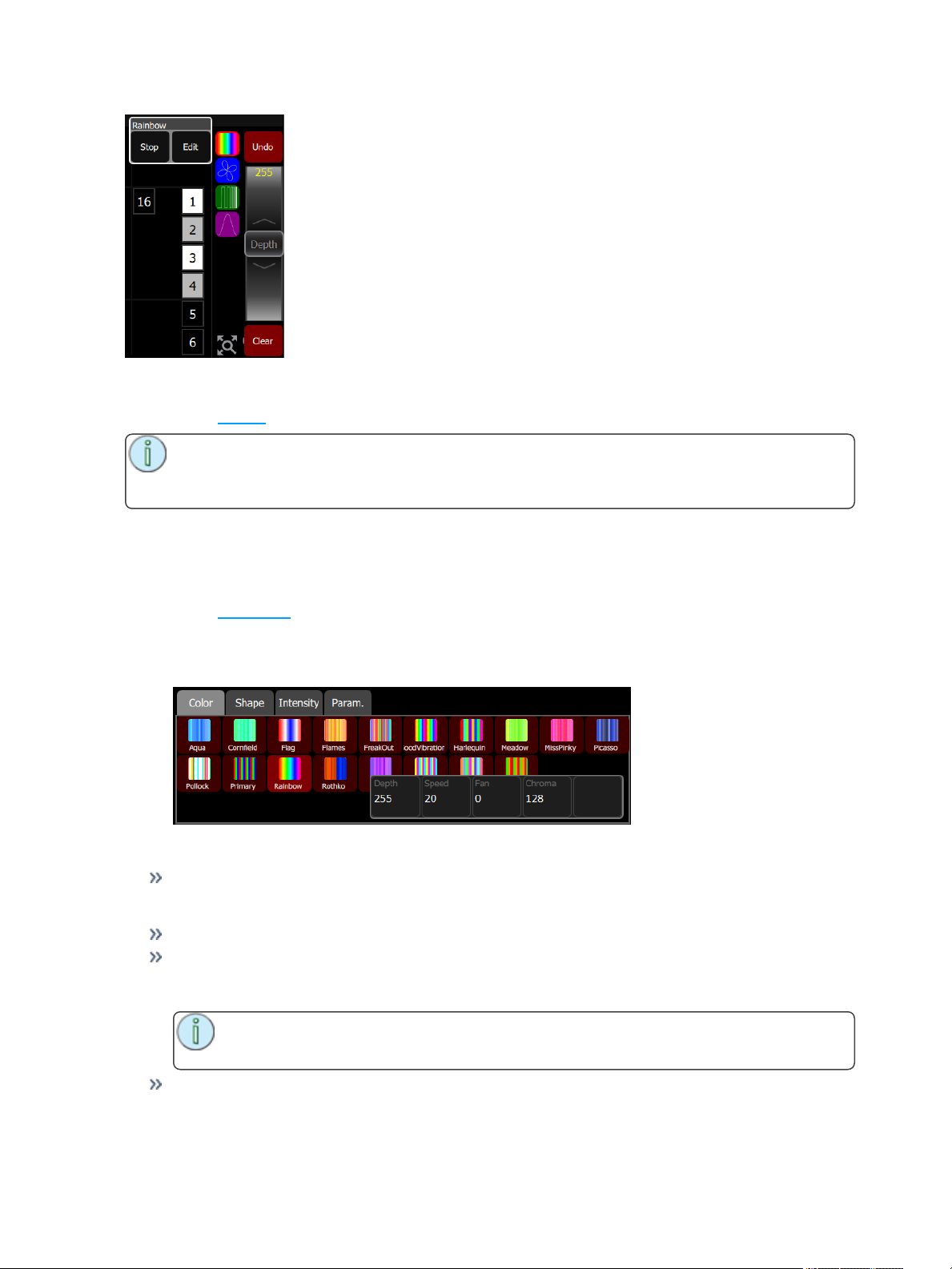
Effects can be stored to cues and playbacks. When effects are played back, a symbol is shown to the right
of the stage map display corresponding to each effect currently in operation. You may pick this symbol and
adjust the depth of the effect on the wheel, edit, or stop it.
Using Effects 43
Page 44
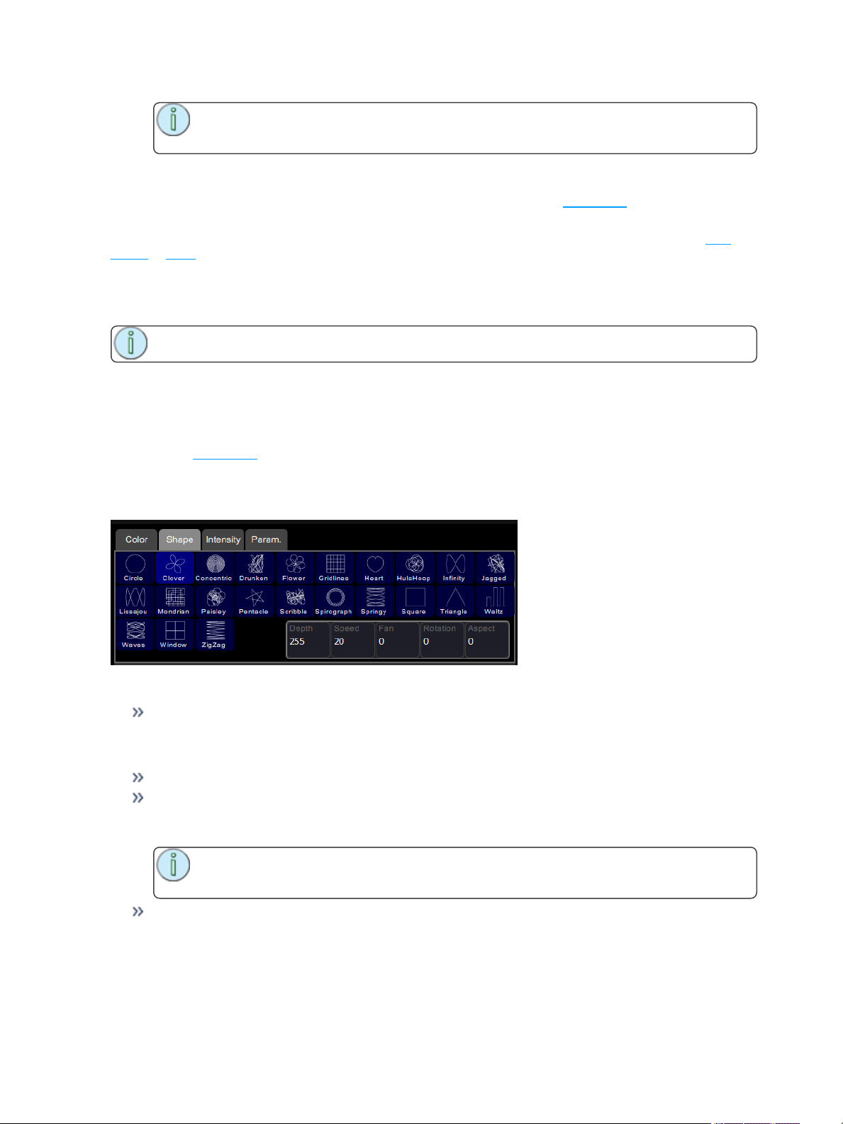
Effect, Color
Applies color effects to selected channels.
Note: The color effect system only works with lights capable of performing color mixing. Color
effects cannot be applied to lights with fixed colors or a choice of single colors on wheels or
scrollers.
How to Apply a Color Effect
1. Select some channels.
2. Go to Controls>Effects.
3. Press Add Effect.
4. Choose the color tab from the tab area.
5. Select a pattern.
6. Adjust the effect settings for the desired result.
Effect Settings
Depth- The amount that the effect deviates from the static color set on the light. When set to full,
the light follows the effect colors entirely. When set to 50%, the resulting colors will be half way
between the light's static rest-state color (the color it was before the effect was chosen), and so on.
Speed- The speed or rate that the effect runs.
Fan- The amount the effect is spread out over the selected lights. Without fan, all the lights change
together at the same time. With increasing the value of fan, the lights respond to different parts of
the effect, offset from each other.
Note: The order in which the lights are selected will affect how they are spread-out by
the fan setting.
Chroma- The intensity of color. Chroma is currently 0-255. 127 = Normal, 0 = Paler, and 255 = Saturated.
44 Using Effects
Page 45
Note: Effects containing fully saturated colors, such as Rainbow, cannot be made
'more' saturated with the Chroma control.
Running Effect Control
When effects run, an icon is displayed in the vertical area to the right of the stage map. This may be selec-
ted at any time to manipulate the effects.
Effects may be edited, removed, or reduced via the wheel control when they are playing back from play-
backs or cues.
Effect, Shape
Applies shape (motion) effects to chosen channels.
Note: The shape effect system only works with lights capable of pan / tilt movement.
How to Apply a Shape Effect
1. Select some channels.
2. Go to Controls>Effects.
3. Press Add Effect.
4. Choose the shape tab from the tab area.
5. Select a pattern.
6. Adjust the effect settings for the desired result.
Adjustments
Depth- The amount that the effect deviates from the static position set on the light. When set to full
the light follows the shape entirely, which will be very large. When set to 50% the resulting Shape
will be half way between the light's static rest-state position (the position it was before the effect
was chosen), and so on.
Speed- The speed or rate that the effect runs at.
Fan- The amount the effect is spread-out over the selected lights. With no fan all the lights change
together at the same time. With increasing values of fan the lights respond to different parts of the
effect, offset from each other.
Note: The order in which the lights are selected will affect how they are spread-out by
the fan setting.
Rotation- The angle of the effect. In the zero setting, 0, the effect is played back normally. As rotation is increased the shape will rotate. The effect of rotation will only be apparent on shapes with distinct edges or asymmetry. For instance, the circle effect looks the same no matter what is the
rotation setting whereas the Square effect appears as a diamond if set to 45 degrees rotation.
Using Effects 45
Page 46
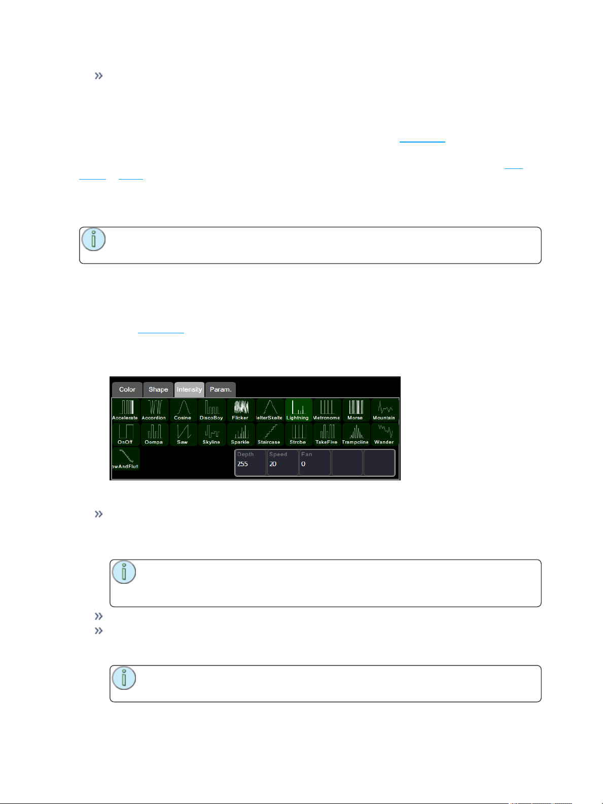
Aspect- Shape effects may be squashed on one of their axes. This can used to fit a shape effect to
a stage area or scenic element. Positive Aspect progressively squashes the tilt axis while negative
Aspect progressively squashes the pan axis.
Running Effect Control
When effects run an icon is displayed in the vertical area to the right of the stage map. This may be selec-
ted at any time to manipulate the effects.
Effects may be edited, removed, or reduced via the wheel control when they are playing back from play-
backs or cues.
Effect, Intensity
Applies intensity effects to chosen channels.
Note: Intensity effects may only be applied to devices that produce light and have an intensity
control channel.
How to Apply an Intensity Effect
1. Select some channels.
2. Go to Controls>Effects.
3. Press Add Effect.
4. Choose the intensity tab from the tab area.
5. Select a pattern.
6. Adjust the effect settings for the desired result.
Effect Settings
Depth- The amount that the effect deviates from the static intensity set on the light. When set to full
the light follows the effect entirely, and will range from zero to full. When set to 50% the resulting
effect will be half way between the light's static rest-state intensity (the brightness it was before the
effect was chosen), and so on.
Note: For the intensity to vary fully between zero and full you should set the rest-state
value to 50%, then the effect can both raise and lower the intensity by the full amount possible.
Speed- The speed or rate that the effect runs at.
Fan- The amount the effect is spread-out over the selected lights. With no fan all the lights change
together at the same time. With increasing values of fan the lights respond to different parts of the
effect, offset from each other.
Note: The order in which the lights are selected will affect how they are spread-out by
the fan setting.
46 Using Effects
Page 47
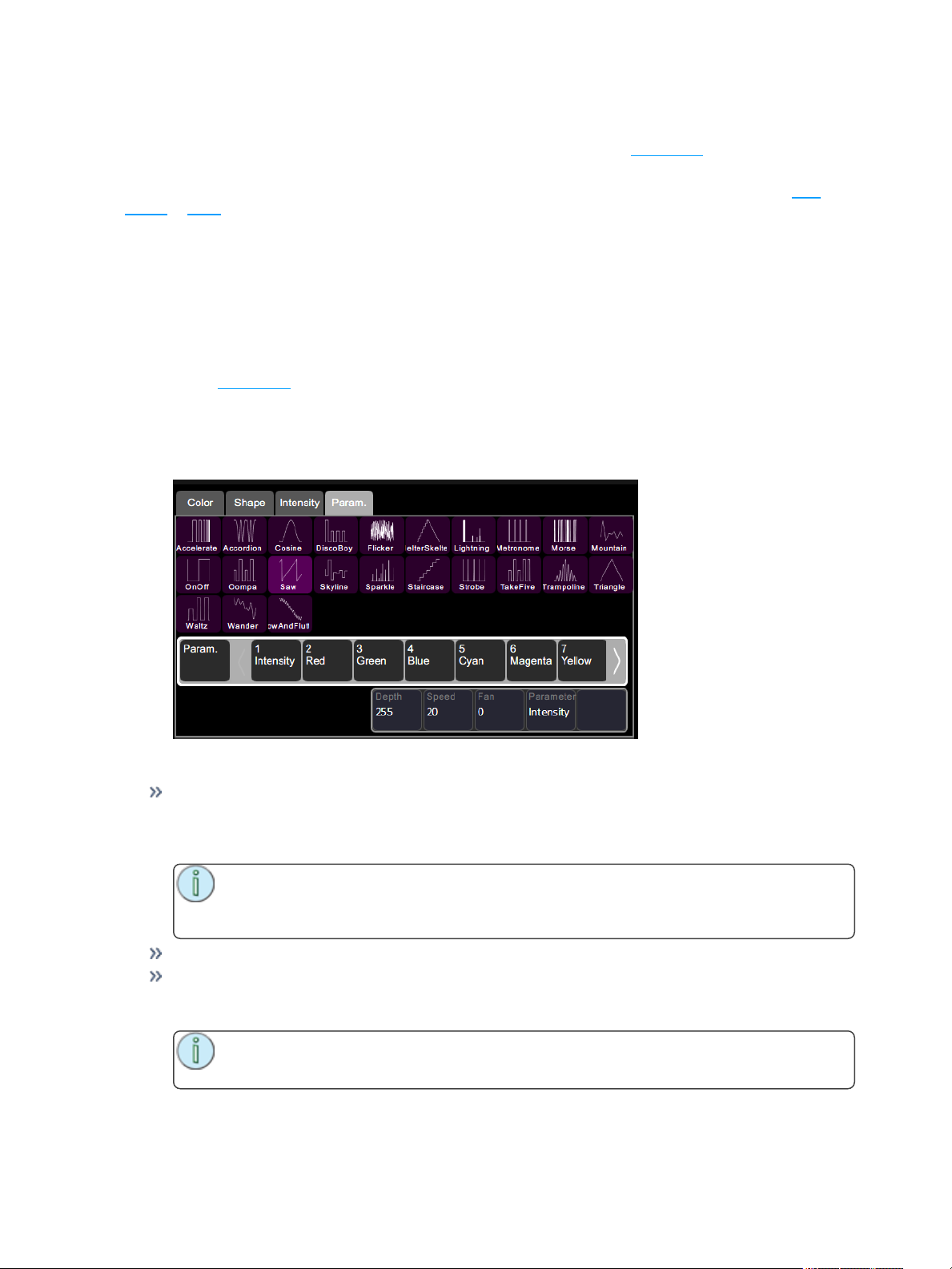
Running Effect Control
When effects run an icon is displayed in the vertical area to the right of the stage map. This may be selec-
ted at any time to manipulate the effects.
Effects may be edited, removed or reduced via the wheel control when they are playing back from play-
backs or cues.
Effect, Parameter
Applies effects to particular parameters of chosen channels.
How to Apply a Parameter Effect
1. Select some channels.
2. Go to Controls>Effects.
3. Press Add Effect.
4. Choose the parameter tab from the tab area.
5. Select a pattern.
6. Choose the parameter to be affected, you will see the effect start.
7. Adjust the effect settings for the desired result.
Effect Settings
Depth- The amount that the effect deviates from the static value set on that parameter of the light.
When set to full the parameter follows the effect entirely, and will range from zero to full. When set
to 50% the resulting effect will be half way between the light's static rest-state for that parameter
(the value it was before the effect was chosen), and so on.
Note: For the parameter to vary fully between zero and full you should set the rest-state
value to 50%, then the effect can both raise and lower the parameter value by the full
amount possible.
Speed- The speed or rate that the effect runs at.
Fan- The amount the effect is spread-out over the selected lights. With no fan all the lights change
together at the same time. With increasing values of fan the lights respond to different parts of the
effect, offset from each other.
Note: The order in which the lights are selected will affect how they are spread-out by
the fan setting.
Using Effects 47
Page 48
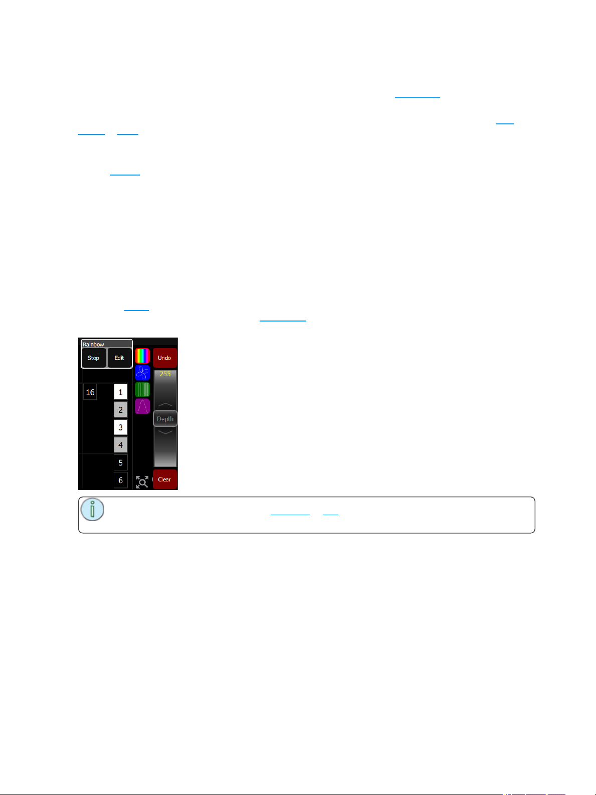
Running Effect Control
When effects run an icon is displayed in the vertical area to the right of the stage map. This may be selec-
ted at any time to manipulate the effects.
Effects may be edited, removed or reduced via the wheel control when they are playing back from play-
backs or cues.
Add Effect
To use effects, select some lights and then press Add Effect. Choose an effect type in the tab area, select
a pattern, and then adjust the effect settings for the desired result.
The order that lights are selected in is relevant and affects the behavior of the Fan setting. Fan refers to the
amount the effect is spread-out over the selected channels. With no Fan all the lights change together at
the same time. With increasing values of Fan the lights respond to different parts of the effect, offset from
each other. Fan is set in the specific effect type tabs.
Several effects may be added to one device or channel and their actions will be combined, for instance a
small circle effect may be applied as well as a large circle effect. The chosen device will then move in small
circles processing round a larger circle.
Remove Effect
Select the effect to be removed on the effect symbol shown in the vertical strip to the right of the Effect display, and press Remove Effect. From the Stage Map, select the effect to be removed on the effect symbol
shown in the vertical strip to the right of the stage map, then press Edit>Remove effect.
Note: If the effect is playing from a playback or cue, you must edit that item to remove the
effect permanently.
48 Using Effects
Page 49
Turning Lights Off
This section covers turning off your lights by using the Blackout or Clear functions.
Clear
Clear functions remove levels coming from various sections; cues, playbacks, and channels under control
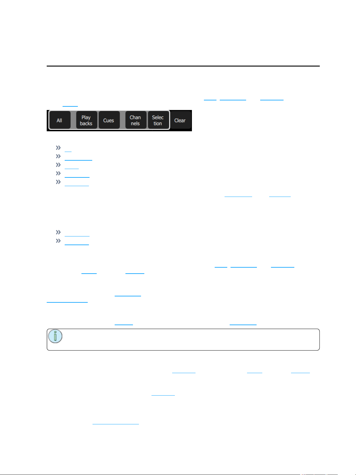
of the wheel.
When Clear is pressed, the following options will be available:
All
Playbacks
Cues
Channels
Selection
Cleared levels fade back using the fade time, which may be set in the Times Tab of the Settings screen.
The default time is 0.5 seconds.
In Simple mode
Clear offers these two options:
Channels - clears levels set on selected channels
Selection - clears the selection set.
Clear All
Clear All removes all levels coming from these various sections; cues, playbacks, and channels under
control of the wheel, faders, or keypad.
Clear Playbacks
Clears the output from the playbacks. The action is the same as taking each playback to zero or taking the
playbacks fader to zero.
Clear Cues
Clears the output from the cue list. The action is the same as taking the cues fader to zero.
Note: The cue list position is not affected. Pressing GO will fade in the next cue after the one
that was cleared.
Clear Channels
Clear Channels removes all levels coming from channels under control of the wheel, faders, or keypad.
Clear Selection
Clear Selection deselects any selected channels, but their levels will remain at the current value.
Speed Clear
Speed Clear is a function that can be assigned to one of the configurable buttons under the touchscreen. It
is assigned in the Settings: Console tab.
Turning Lights Off 49
Page 50
By pressing the Speed Clear button a certain number of times, you can perform the following clear functions:
1. Deselect - pressing the speed clear button once deselects any selected channels, but their levels
will remain at the current value.
2. Clear channels - pressing the speed clear button twice removes all levels coming from channels
under control of the wheel, faders, or keypad.
3. Clear playbacks - pressing the speed clear button three times clears the output from the playbacks.
The action is the same as taking each playback to zero or taking the playbacks fader to zero.
4. Clear cues - pressing the speed clear button four times clears the output from the cue list. The
action is the same as taking the cues fader to zero.
Note: The cue position is not affected. Pressing GO will fade in the next cue after the
one that was cleared.
Blackout
Blackout sets all lighting levels to zero. The Blackout function can be assigned to one of the buttons below
the touchscreen. See Settings: Console (on page71) for more information.
Note: Independents can be included or excluded from the effect of Blackout.
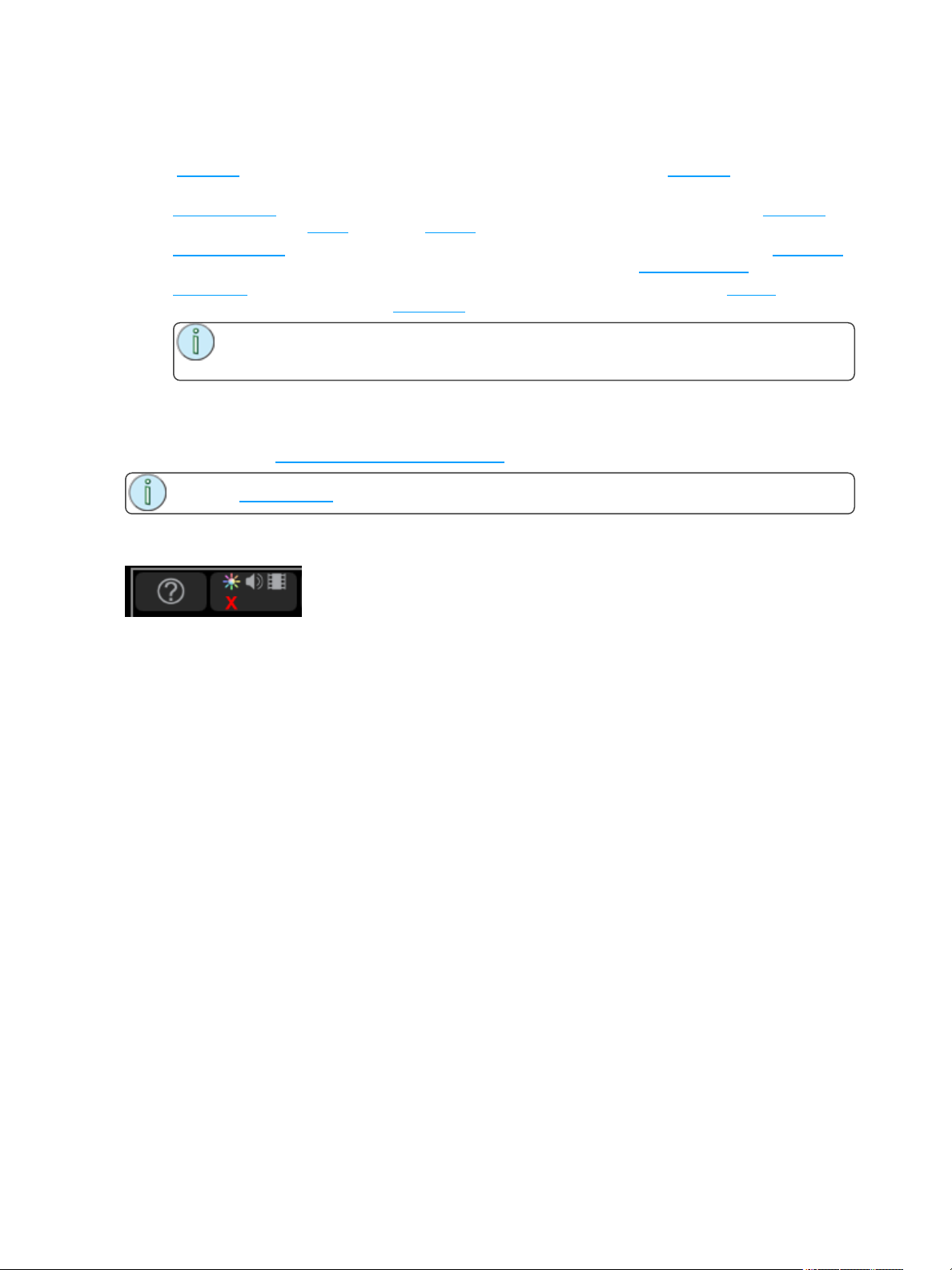
When Blackout is engaged a red X appears below the light bulb icon in the control box adjacent to the Help
button.
50 Turning Lights Off
Page 51
Special Functions
This section covers the use of the Playback Toy and Independents.
The Playback Toy is a display where you can control playbacks and sequences.
Independents can be used to control certain devices and can have special settings applied to them.
Independent
Operates the independent outputs, 1 or 2.
Independents may be used to operate on/off devices such as motors, smoke machines, cue lights et cetera.
Independents may be set to operate as momentary bumps or as push-on / push-off latching switches.
Independents may be set with an on-level and you may choose to include or exclude them from blackout.
The independent settings and patch are on the Ind. Tab in settings.
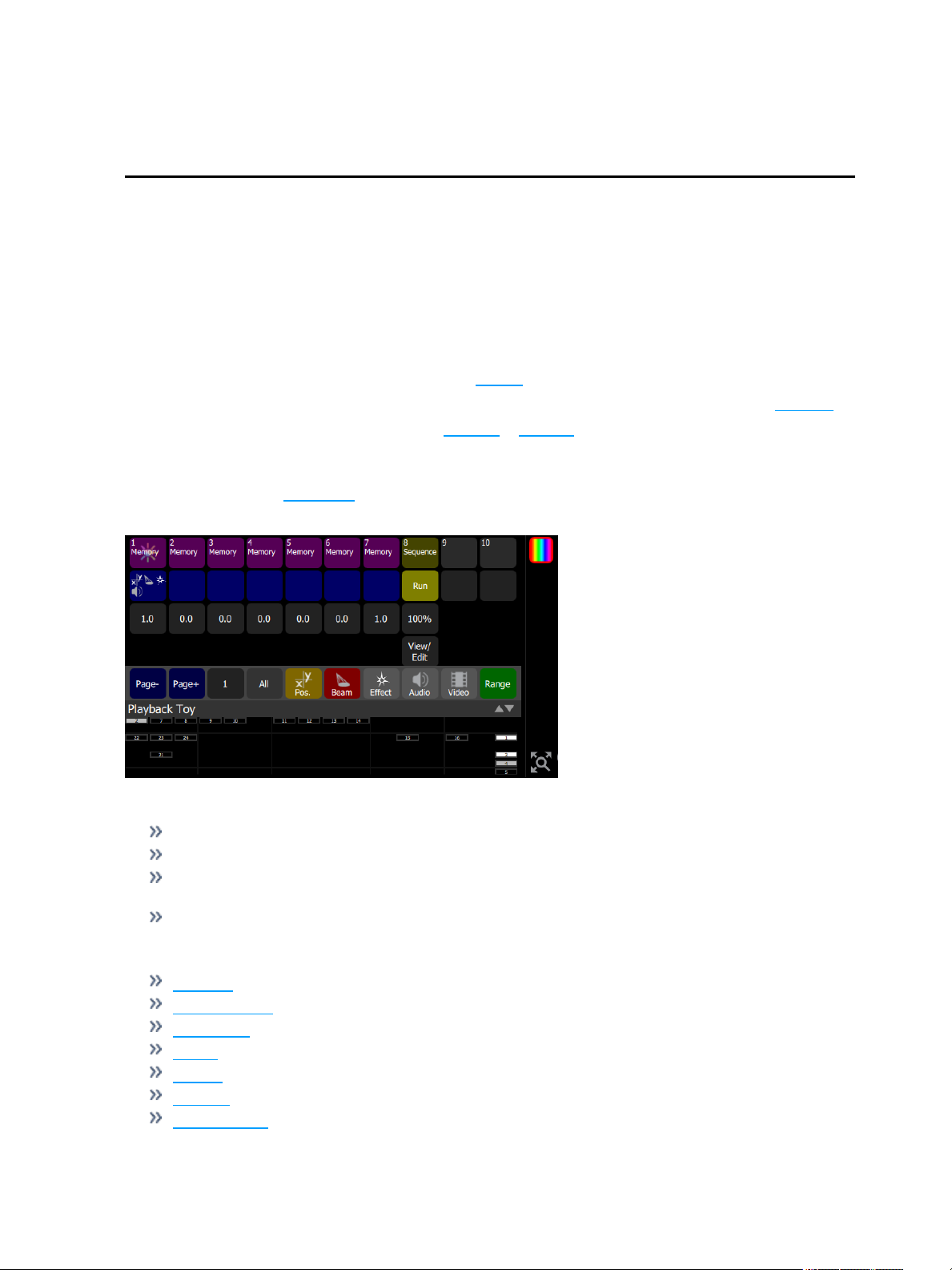
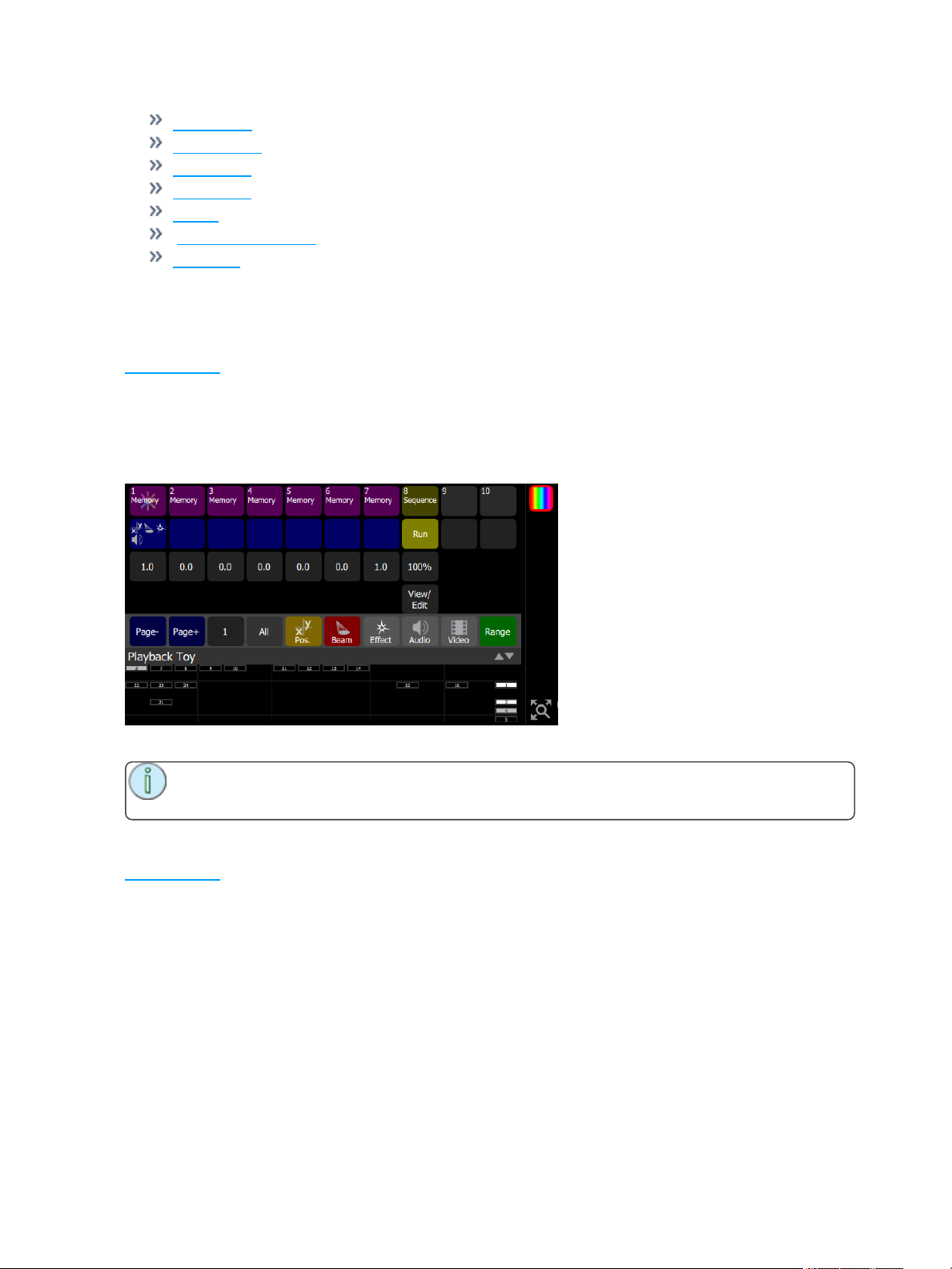
Playback Toy
This screen shows ten playbacks from the current playback page.
Playbacks can be viewed and operated here.
Operation
Press on a top-row mauve cell to select and fade in that lighting scene.
Hold on top-row cell to edit its name.
Press a mid-row blue cell to operate the parameters for that playback, turn on and off filters to
choose the parts to play-back.
Press and hold a bottom-row grey cell to change the fade time.
Functions
Intensity
Parameter GO
Time/ Rate
Page Page +
All Filter
Position Filter
Special Functions 51
Page 52
Beam Filter
Effects Filter
Audio Filter
Video Filter
Range
Sequence Run/Step
View/Edit
The page number or name is shown to the right of the Page - and Page + buttons. Hold the button to
change the page name.
Intensity
Playback Toy provides a simple way to play one playback or sequence at a time with a single press.
The Intensity button, shown in mauve for playbacks and yellow for sequences, plays only the intensity part
of a recorded look. The parameter part of a look may be played independently, including from a different
look than the one chosen to play the intensity.
When a playback or sequence is chosen, the previous one is faded out and replaced with the newly-chosen
one.
You may mix one intensity look with another parameter look to make a new combination look.
Note: You may enter names for playbacks by holding the Intensity button down until a key-
board appears for name entry.
Parameter GO
Playback Toy provides a simple way to play one playback or sequence at a time with a single press. When
a playback or sequence is chosen, the previous one is faded out and replaced with the newly-chosen one.
The Parameter GO button, shown in blue, plays only the parameter part of the look. The intensity part may
be played independently, including from a different playback or sequence than the one chosen to play the
parameters.
The blue button indicates the types of parameters contained in the playback.
52 SpecialFunctions
Page 53
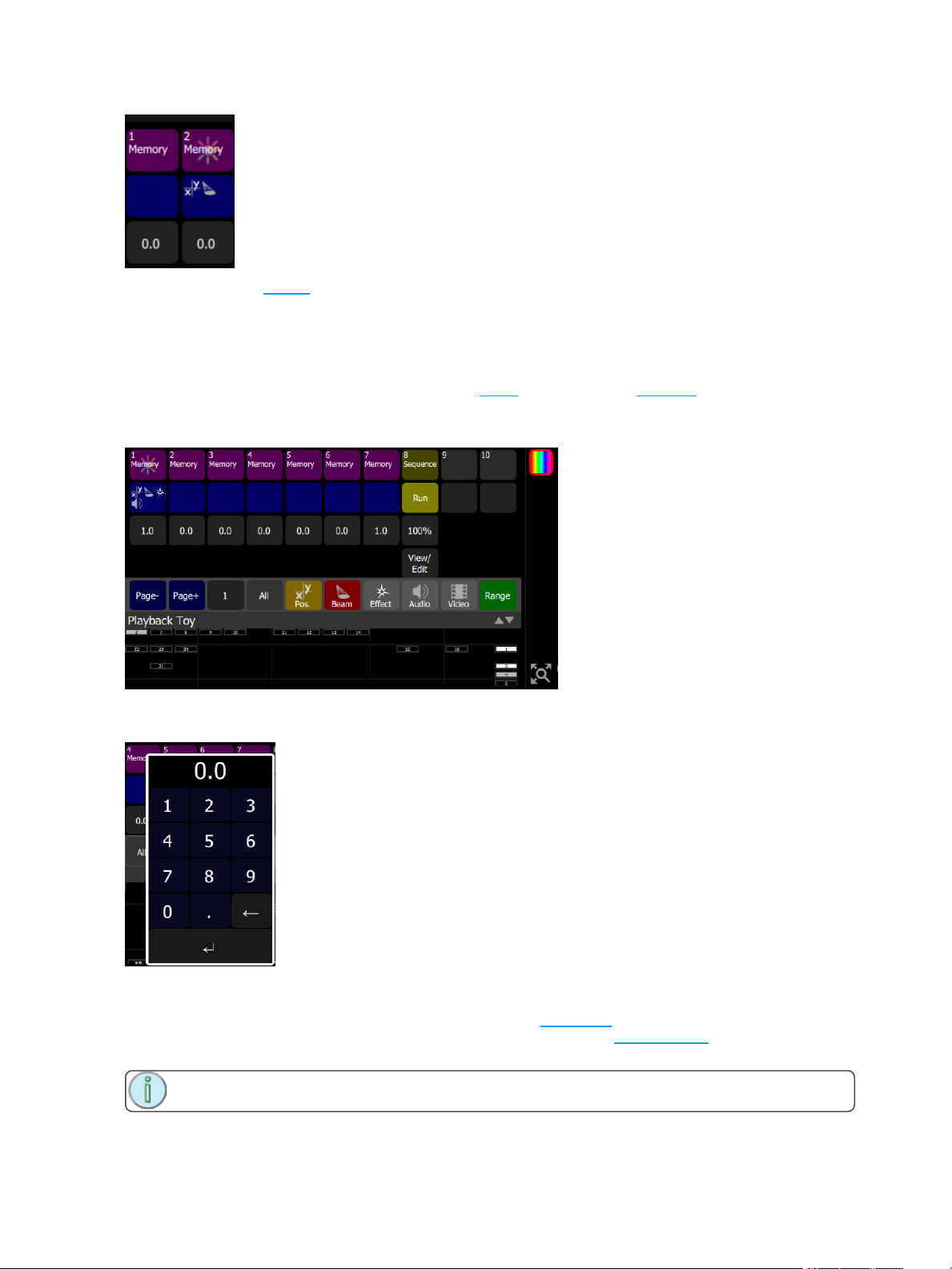
Parameters may be filtered so you can choose which types of parameters to play, for example you could
choose to only play the position part by turning off (filtering) the other parameters such as beam.
You may mix one intensity look with another parameter look to make a new combination look.
Time/ Rate
Playbacks may be given a fade time. When either a bump or Playback Toy Intensity button is pressed, the
intensity and parameter parts will fade in at the rate set on the Time button, shown in gray.
If the playback contains a sequence, the gray button will indicate the rate.
Holding down the gray button will open a keypad to alter the time (for playbacks) or the Rate (for
sequences).
Playback Page Selection, Minus
Picks the playback page to switch to. There are ten pages of playbacks. The page will change for the next
time a fader is raised from the zero position or a playback is launched in Playback Toy on a mauve or blue
button.
Note: Faders that are up at a level will not change immediately and must first be taken to zero.
Special Functions 53
Page 54
The page number or name is shown to the right of the Page - and Page + buttons. Hold the name / num-
ber button to change it.
Playback Page Selection, Plus
Picks the playback page to switch to. There are ten pages of playbacks. The page will change for the next
time a fader is raised from the zero position or a playback is launched in Playback Toy on a mauve or blue
button.
Note: Faders that are up at a level will not change immediately and must first be taken to zero.
The page number or name is shown to the right of the Page - and Page + buttons. Hold the name / num-
ber button to change it.
Playback Page Name / Number
There are ten pages of playbacks.
The page number or name is shown to the right of the Page - and Page + buttons. Hold the name / num-
ber button to change it.
Filter, All
Filtering is useful to play parts of a playback and leave other parts unaffected. Using this method you can
play the pan/tilt part of one playback, the gobo and beam parts of a second playback, and the intensity and
color mixing parts of a third playback to make a new composite playback.
The All button toggles between all parameters on and all parameters off.
Switch off a parameter to exclude it from playback when operating the blue GO buttons.
Note: If all parameters are off, the blue GO button will not do anything. However, the mauve
intensity button can still launch the intensity and color mixing parts of the chosen playback.
Filter, Audio
Filtering is useful to play parts of a playback and leave other parts unaffected. Using this method you can
play the pan/tilt part of one playback, the gobo and beam parts of a second playback, and the intensity and
color mixing parts of a third playback to make a new composite playback.
The Audio button toggles between audio on and audio off.
Switch off audio to exclude audio from playback when operating the blue GO buttons.
Note: If all parameters are off, the blue GO button will not do anything. However, the mauve
intensity button can still launch the intensity and color mixing parts of the chosen playback.
Filter, Beam
Filtering is useful to play parts of a playback and leave other parts unaffected. Using this method you can
play the pan/tilt part of one playback, the gobo and beam parts of a second playback, and the intensity and
color mixing parts of a third playback to make a new composite playback.
The Beam button toggles between beam on and beam off.
Switch off beam to exclude it from playback when operating the blue GO buttons.
Note: If all parameters are off, the blue GO button will not do anything. However, the mauve
intensity button can still launch the intensity and color mixing parts of the chosen playback.
54 SpecialFunctions
Page 55
Filter, Effect
Filtering is useful to play parts of a playback and leave other parts unaffected. Using this method you can
play the pan/tilt part of one playback, the gobo and beam parts of a second playback, and the intensity and
color mixing parts of a third playback to make a new composite playback.
The Effect button toggles between effects on and effects off.
Switch off effect to exclude effects from playback when operating the blue GO buttons.
Note: If all parameters are off, the blue GO button will not do anything. However, the mauve
intensity button can still launch the intensity and color mixing parts of the chosen playback.
Filter, Position
Filtering is useful to play parts of a playback and leave other parts unaffected. Using this method you can
play the pan/tilt part of one playback, the gobo and beam parts of a second playback, and the intensity and
color mixing parts of a third playback to make a new composite playback.
The Position button toggles between position on and position off.
Switch off position to exclude it from playback when operating the blue GO buttons.
Note: If all parameters are off, the blue GO button will not do anything. However, the mauve
intensity button can still launch the intensity and color mixing parts of the chosen playback.
Filter, Video
Filtering is useful to play parts of a playback and leave other parts unaffected. Using this method you can
play the pan/tilt part of one playback, the gobo and beam parts of a second playback, and the intensity and
color mixing parts of a third playback to make a new composite playback.
The Video button toggles between video on and video off.
Switch off video to exclude video from playback when operating the blue GO buttons.
Note: If all parameters are off, the blue GO button will not do anything. However, the mauve
intensity button can still launch the intensity and color mixing parts of the chosen playback.
Range
Playback Toy displays ten playbacks at a time. To see further playbacks, press Range to switch between
them.
Special Functions 55
Page 56

56 SpecialFunctions
Page 57

AV Functions
This section covers the media functionality of the ColorSourceAVconsole. Also covered is OSC function
and using Amigo Web Browser.
The following topics are covered:
Use of Media 57
Media 57
Media, Audio 58
Audio Input and Output Help 59
Media, Video 60
Audio Mute 61
Media Pause 61
Video Off 61
S2L Lights 62
S2LVideo Toy 62
OSC Commands 63
Amigo Remote Web Browser 65
Connecting the Amigo Remote Web Browser via WiFi 65
Connecting to the Amigo Remote Web Browser by Cable 67
Using Help with the Remote Web Browser 68
Use of Media
It is your sole responsibility to ensure that all media that you import into or export from the ColorSource AV
console is rightfully yours to use and that such usage is legal. ETC asks that you comply with all applicable
laws regarding the usage of media on or with this console, including copyright laws.
Media
The Media system provides audio and Video Toy controls. Media may be played directly, or may be recorded into Cues and Playbacks.
A video synthesizer called Video Toy is included for generation of image effects. Video Toy may be driven
by the user or from audio via the Sound2Light system.
The Sound2Light system provides automated lighting control driven by a sound source; external or internal
sounds may be used.
All pre-recorded media must be loaded in to the console from an external memory stick using the File -
Media Import function.
Supported file types are:
Audio: mp3, aac and wav files (44.1kHz sample rate, 4GB maximum file size)
Image: jpg, png, tiff, and bmp files (1280 x 720 max size)
An audio mixer is provided to control sound from internal playback and the external audio input jack.
AV Functions 57
Page 58
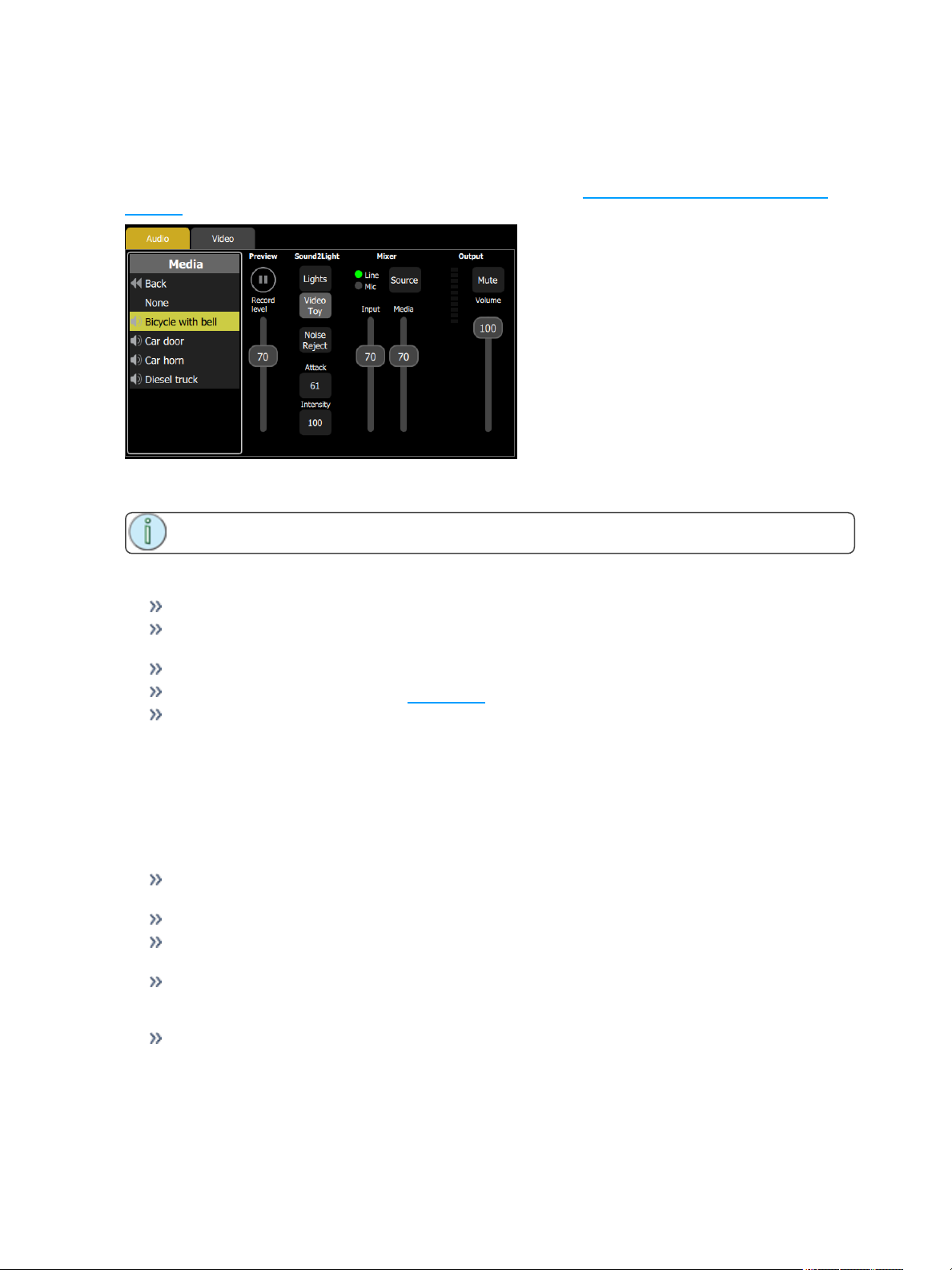
Media, Audio
To open the Audio tab, go to Controls >Media. Here you can choose audio clips to play or record. You can
also operate the mixer to control audio volume and the external input on the rear panel.
For additional information about Audio input and output, please see Audio Input and Output Help on
page 59.
Browse the clip files to find a sound to play and try it on the local player on this screen. If a clip is playing
when a recording is made, you will be asked if you wish to include it in the recording.
Note: The audio mixer also feeds the Sound2Light converter.
Audio Mixer
Input: Controls the input level from the external socket on the rear panel.
Source: Selects the source of input audio from either the internal microphone or the external line
input socket.
Media: Controls the playback level of audio clips in playbacks and cues.
Mute: Mutes all audio output. See Audio Mute for more information.
Volume: Controls the volume of the final output going to the output jack.
Sound2Light
The Sound2Light processor drives the first six playback faders according to the frequencies contained in
the sound. Low, bass, frequencies go to Playback #1, higher to #2 and so on to #5 driven by high treble
sounds.
When there is no sound Playback #6 is activated as a rest or silent background state. The rest state is
driven after a delay so that it only appears when a sound clip has finished.
Lights: Sends Sound2Light to the first 6 playback faders. You must program content into these to
see the Sound2Light effect.
Video Toy: Sends Sound2Light to the VideoToy video synthesizer.
Noise reject: Turn this on if the sound source is noisy with hum or hiss, or there is high background
noise if the Mic input is being used.
Attack: Low values produce sudden changes tracking the sound rapidly and on VideoToy produces
strong primary colors, high values result in slower and smoother response and more pastel or paler
colors in VideoToy.
Intensity: The brightness of the Sound to Light effects on either Lights or VideoToy.
58 AV Functions
Page 59
Audio Input and Output Help
Input Type
3.5mm (1/8”) TRS, Stereo, unbalanced
Max Peak Input: -10dBV (316mV RMS)
Input Impedance: 29k ohms
Output Type
3.5mm (1/8”) TRS, Stereo, unbalanced
Max Output : -10dBV (316mV RMS) at 10k ohms “Line Level”
Load Impedance : 10k – 200k ohms
Warning: NEVER connect the input if levels are directly from an amplifier or loudspeaker con-
nection. Doing so may result in damage.
Warning: NEVER connect the output to a balanced input that has 48V microphone phantom
power enabled. Doing so may result in damage.
Note: The output is stereo unbalanced and should not be connected to a balanced input as very
poor sound quality will result.
Audio Input Tips
Line or headphone output of consumer or professional audio equipment is recommended.
If the input source level is too low turning up the input fader may produce noise. If the input level is
too high it may distort.
Audio Output Tips
Line level output is not suitable for connection to headphones. Although some sound can be heard in
headphones, and it may be useful from time to time, the volume and quality will not usually be satisfactory.
Connection to a load with a lower impedance (fewer ohms) will result in distortion and loss of bass.
There is no upper limit for the load impedance, but very high impedance loads might result in some
noise being heard.
When possible connect directly to mixer or power amplifier “line level” inputs.
If the input impedance is less than 10k ohms it is advisable to insert a suitable pre-amplifier between
the console and the mixer/amplifier.
Preventing hum
When the ColorSource AV console is connected to external audio equipment, and some other peripherals, audible hum may be produced. This is usually due to a phenomena known as a ground-loop
or hum-loop where several pieces of equipment are grounded independently and then also to each
other.
Ground loops can sometimes be cured by simple means including re-arranging the grounding of the
mixer/amplifier and source of sound. You should ask a competent electrician to perform any
changes of grounding as it could affect equipment safety.
AV Functions 59
Page 60
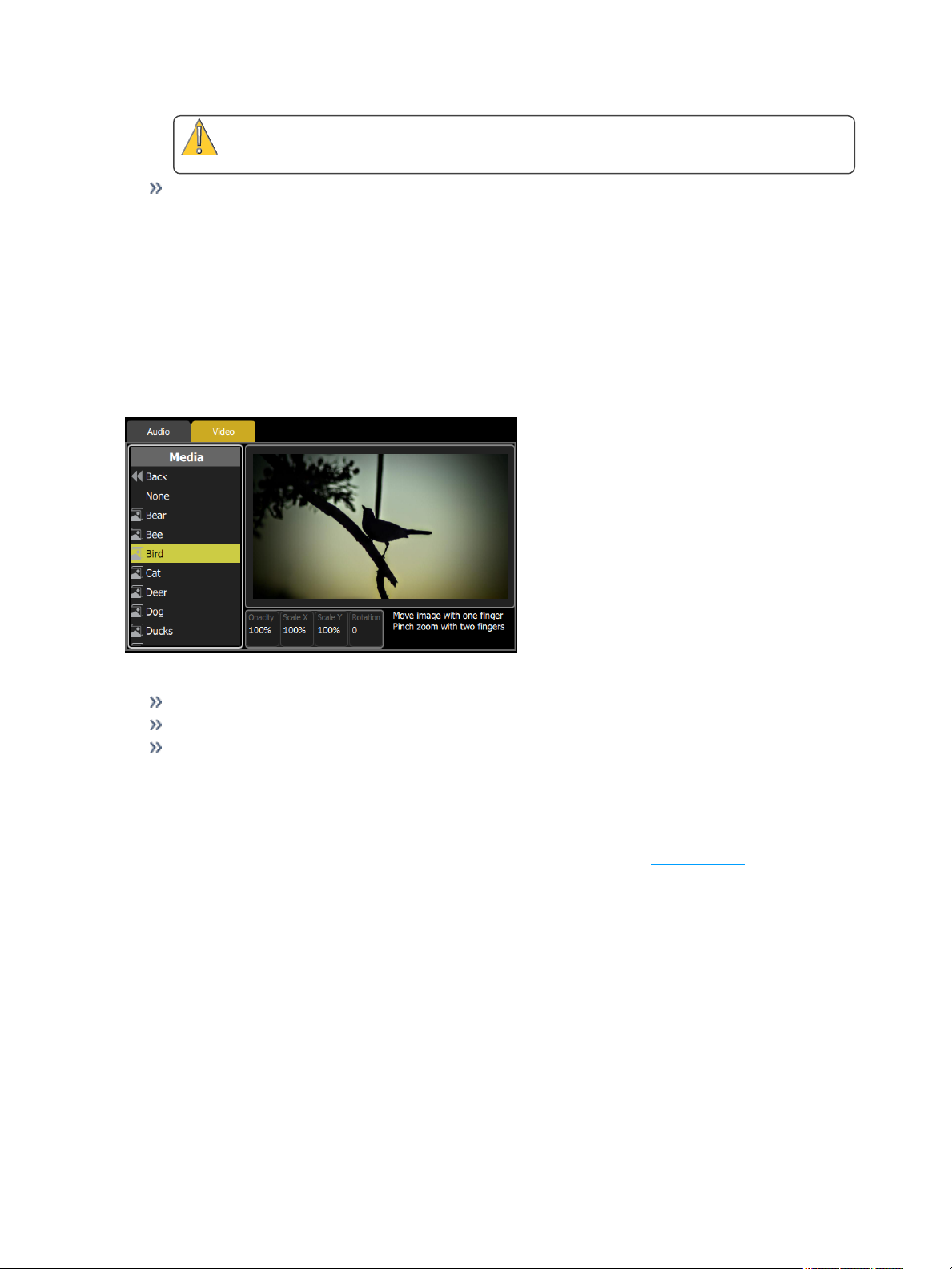
Caution: You should ask a competent electrician to perform any changes of grounding
as it could affect equipment safety.
If hum cannot be cured easily you should consider using a Direct Injection (DI) box. You will need a
stereo DI box on either the input or the output, and exceptionally on both. DI boxes are readily obtainable from music stores. You need a fully isolated type.
Media, Video
To open the Video tab, go to Controls >Media. Here you can choose still image or Video Toy pattern to
play or record.
Browse the clip files to find an image or Video Toy pattern to play or record, and try it on the local player on
this screen. If a clip is playing when a recording is made you will be asked if you wish to include it in the
recording.
Images
Image Controls
Opacity: Controls the brightness or luminance of the image, if set to zero the image will be invisible.
Scale X & Y: Controls the size of the two picture dimensions.
Rotation: Alters the angle of the projected image.
Additionally, images may be manipulated on-screen with pinch-zoom and pan gestures.
Video Toy
Video Toy is a video synthesizer tool that can create patterns and images for scenic effects. Patterns may
be run automatically, by on-screen finger gestures, or may be driven from the Sound 2 Light system.
Browse the included pattern files in Video >Media > Effects folder to find a pattern to play and try it on the
local player on this screen. If a Video Toy pattern is playing when a recording is made, you will be asked if
you wish to include it in the recording.
60 AV Functions
Page 61
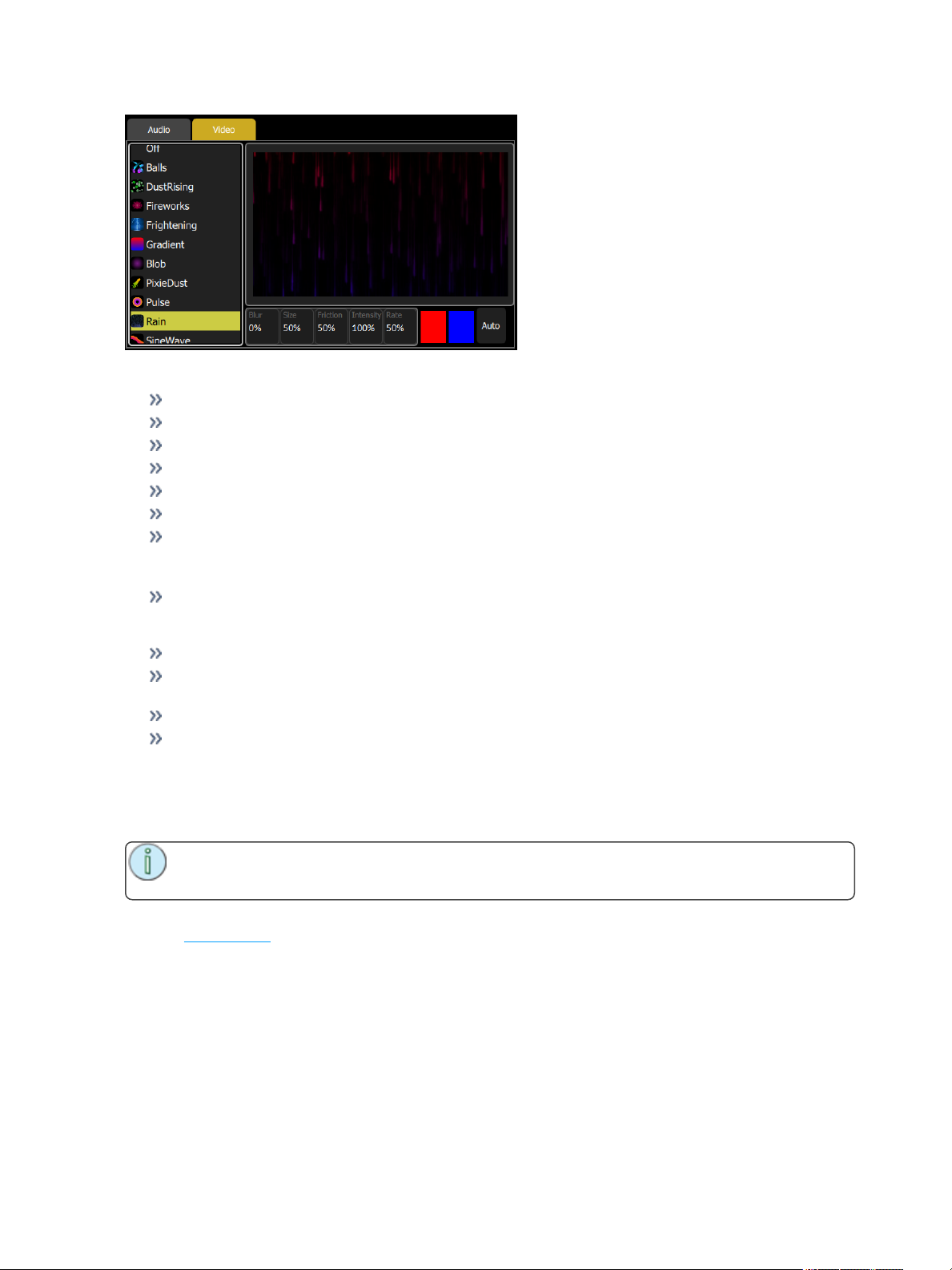
Video Toy Controls
Blur: The degree to which pattern elements remain in view or fades away.
Size: Adjusts the size or scale of pattern features.
Friction: Modifies the way pattern elements interact with each other.
Intensity: Adjusts the brightness of the resulting lighting levels.
Rate: Adjusts the rate or speed that pattern elements move or change.
Color: The two color boxes select the range of colors used in pattern generation.
Auto: Pressing Auto will open up a display with the following controls:
Auto Controls
Paint: At low settings, strong colors are painted on a black background. In the center position,
strong colors are painted on top of each other. At the top position, the paint strength is reduced for
more subtle changes to the accumulated picture.
Speed: The rate or speed that pattern elements move or change.
Movement: The degree to which painting is spread around the canvas. At low settings, all painting
is in the center, or propagates from the center. At high settings, painting occurs all over the canvas.
Density: The quantity and/or size of pattern elements.
Swirl: A dynamic rotating distortion for added movement.When set to 50, there is no swirl. At low
settings, the swirl contracts the image. At high settings, it spreads the image.
Audio Mute
Mutes all audio output.
Note: Audio will continue to play silently. When audio is un-muted, the track will have moved
on or may have completed.
All audio is muted, whether from external input, a clip, or video soundtrack playback. Audio Mute does not
stop the Sound2Light system.
Media Pause
Pauses all running media.
Audio will stop at its current position. When Media Pause is disengaged, audio will resume playing from its
paused position.
Video Off
Blanks the video output to black.
AV Functions 61
Page 62

All video output is blanked, whether from a still image or Video Toy pattern.
S2L Lights
Turns on or off the Sound2Light Lights function.
S2LVideo Toy
Turns on or off the Sound2Light Video Toy function.
62 AV Functions
Page 63
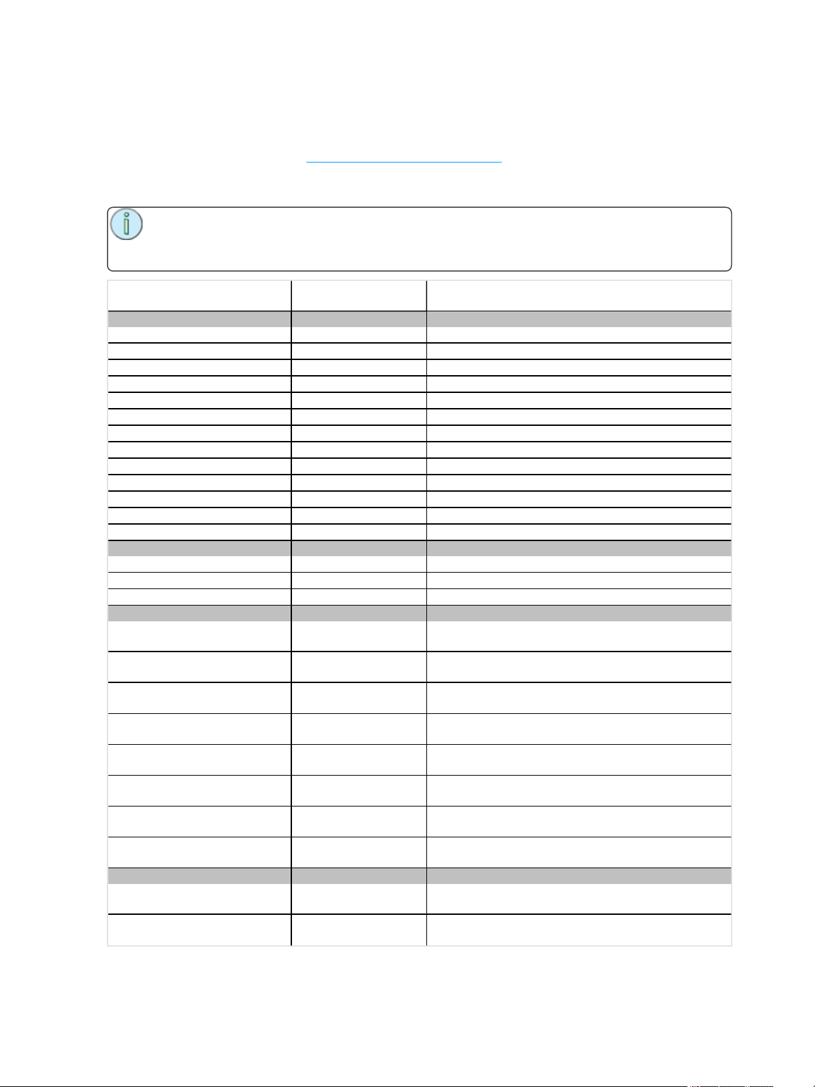
OSC Commands
OSC is a protocol that uses network communication (wired or wireless) to communicate between various
audio, video, and lighting devices, and other devices, such as tablets for remote control of your console.
For configuration information, see Settings: Network (on page72).
The following is a list of the OSCcommands, their variables or arguments, if any, and a description of its
function.
Note: Arguments are shown following an equal sign (=). For OSC, these are not sent as a part
of the OSC string itself, but instead attached as arguments. Configuration will vary depending on
the software you are using.
Command
Buttons
/cs/key/recordsnapshot Records asnapshot of the active state in a memory
/cs/key/recordnextcue Records the active state into the next cue
/cs/key/clearall Clears all the selections, active channels,playbacks and cues
/cs/key/clearplaybacks Clears the active playbacks
/cs/key/clearcues Clears the active cue
/cs/key/clearchannels Clears the active channels
/cs/key/clearselection Clears the user's selected channels
/cs/key/blackout Toggles the blackout state
/cs/key/audiomute Togglesaudio mute
/cs/key/videooff Togglesvideo output
/cs/key/mediapause Pauses or plays media
/cs/key/ind1 TogglesInd1
/cs/key/ind2 TogglesInd2
Cue
/cs/playback/go Runs the next cue
/cs/playback/goback Runs the previous cue
/cs/playback/pause Pauses an active cue change
Channels
/cs/chan/select/{x}
/cs/chan/select=x
/cs/chan/add/{x}
/cs/chan/add=x
/cs/chan/subtract/{x}
/cs/chan/subtract=x
/cs/chan/thru/{x}
/cs/chan/thru=x
Groups
/cs/locationGroup/select/{x}
/cs/locationGroup/select=x
Variables / Argu-
ments
x: channelnumber, no
arguments
x: channelnumber, 1
integer argument
x: channelnumber, no
arguments
x: channelnumber, 1
integer argument
x: channelnumber, no
arguments
x: channelnumber, 1
integer argument
x: channelnumber, no
arguments
x: channelnumber, 1
integer argument
x: location group number,
no arguments
x: location group number,1 integer argument
Description
Exclusively select channelx
Exclusively select channelx
Add channelx to selection
Add channelx to selection
Remove channel x from selection
Remove channel x from selection
Select every channelf rom the last channelselected 'thru' to channel x
Select every channelf rom the last channelselected 'thru' to channel x
Selects all the channels in the location group x
Selects all the channels in the location group x
AV Functions 63
Page 64
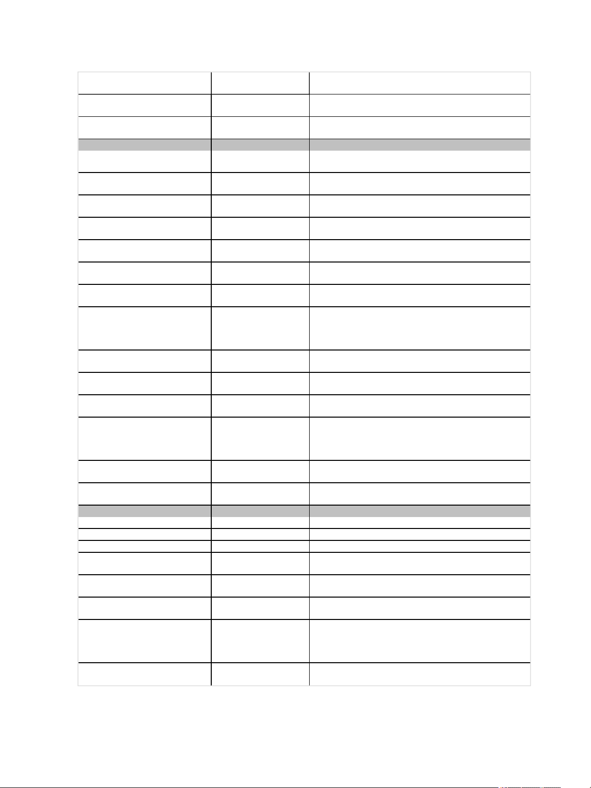
Command
/cs/tagGroup/select/{x}
/cs/tagGroup/select=x
Level- Params- Color
/cs/chan/at/{x}
/cs/chan/at=x
/cs/chan/wheel/{x}
/cs/chan/wheel=x
/cs/param/pan/wheel/{x}
/cs/param/pan/wheel=x
/cs/param/panTilt/{x}/{y}
/cs/param/panTilt = x, y
/cs/param/tilt/wheel/{x}
/cs/param/tilt/wheel=x
/cs/color/hs/{x}/{y}
/cs/color/hs = x, y
/cs/color/select/{x}
/cs/color/select=x
Playbacks
/cs/playback/{x}/activate x: playback number Activates the playback x
/cs/playback/{x}/execute x: playback number Executes the playback x
/cs/playback/{x}/fire/press x: playback number Performs bump button press for playbackx
/cs/playback/{x}/fire/{y}
/cs/playback/x/fire/y No arguments
/cs/playback/x/fire =y
/cs/playback = x, “fire”, y
/cs/playback/{x}/level/{y}
Variables / Argu-
ments
x: tag group number, no
arguments
x: tag group number,1
integer argument
x: value[0-100], no arguments
x: value[0-100],1 integer
argument
x: step amount [0-255], no
arguments
x: step amount [0-255],1
integer argument
x: step amount, no arguments
x: step amount,1 integer
argument
x: pan value [0-100]
y: tilt value [0-100]
x: pan value [0-100]
y: tilt value [0-100], 2
integer arguments –pan,
tilt
x: step amount, no arguments
x: step amount,1 integer
argument
x: hue value [0-360]
y: saturation value [0-100]
x: hue value [0-360]
y: saturation value [0-100],
2 integer arguments - hue,
saturation
x: color chip number, no
argument
x: color chip number, 1
integer argument
x: playback number
y: toggle [0 or 1]
1 argument –button
pressed (integer)
3 arguments –playback
number (integer), “fire”
(string), button pressed
(integer)
x: playback number
y: level [0.0-1.0]
Description
Selects all the channels in the tag group x
Selects all the channels in the tag group x
Puts the selected channelat levelx
Puts the selected channelat levelx
Steps the selected channel'slevelby x
Steps the selected channel'slevelby x
Steps the selected channel'span valueby x
Steps the selected channel'span valueby x
Steps the selected channel'span valueby x and tilt valueby y
Steps the selected channel'span valueby x and tilt valueby y
Steps the selected channel'stilt valueby x
Steps the selected channel'stilt valueby x
Sets the selected channel'scolor to hue x and saturation y
Sets the selected channel'scolor to hue x and saturation y
Sets the selected channel'scolor to the color chip x
Sets the selected channel'scolor to the color chip x
Controls bump button press for playbackx, 1 for button
pressed, 0 for button released
Controls bump button press for playbackx, 1 for button
pressed, 0 for button released
Controls bump button press for playbackx, 1 for button
pressed, 0 for button released
Controls bump button press for playbackx, 1 for button
pressed, 0 for button released
Sets the levelof playback x to value y
64 AV Functions
Page 65
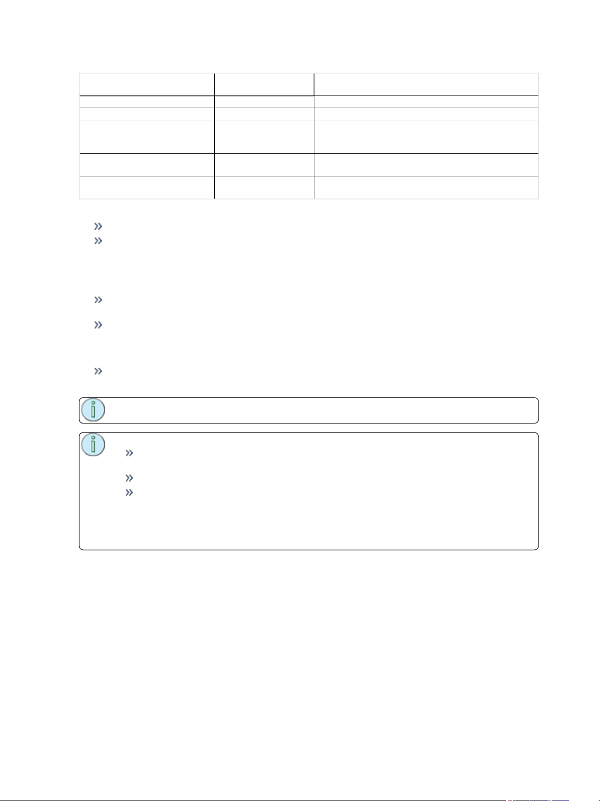
Command
/cs/playback/x/level/y No arguments Sets the level of playback x to valuey
/cs/playback/x/level = y 1 argument –level(float) Sets the levelof playback x to value y (0.0 to 1.0)
/cs/playback = x, “level”,y
/cs/playbacks/changePage/{x}
/cs/playbacks/changePage=x
Variables / Argu-
ments
3 arguments –playback
number (integer), “level”
(string), level(float)
x: step amount, no argument
x: step amount, 1 integer
argument
Description
Sets the levelof playback x to value y (0.0 to 1.0)
Pages the current playback page by x (typically +1 or -1)
Pages the current playback page by x (typically +1 or -1)
Examples
/cs/playback/12/fire = 1 Presses the bump button for playback 12
/cs/playback = 12, “fire”, 1 Presses the bump button for playback 12
Amigo Remote Web Browser
The Amigo Web Browser Interface can be used for various purposes. Some typical applications are:
Remote Control- Remotely control a ColorSource AV console from another location (stage, audience) using a smartphone or tablet computer.
Console Extension- Add control displays to your physical ColorSource AV console. A tablet or
laptop may be used close to the console to provide additional views on a larger screen. This minimizes the switching of views on the console display. For example, to choose quick selects, pick
colors, or operate pan/tilt.
Interactive Help- The Web Interface displays related help in real-time based on the operations of
your ColorSource AV console. This is a great way to quickly learn the console.
Note: Amigo is intended to be used by one user at a time.
Note:
It is not recommended to connect the console to a general purpose office or home network
or a network open to the internet.
It is recommended to use a closed private network dedicated to lighting control.
It is recommended to leave the IP address on the console as Auto on the Setup>Set-
tings>Network tab unless you understand how to set-up manual IP addressing. Remember that if you make a shortcut on your computer to this address, when configured in Auto
mode, it may cease working in a later session if the console acquires a different IP
address.
Connecting the Amigo Remote Web Browser via WiFi
To operate your ColorSource AV console from a web browser, please follow these steps:
Automatic Connection with QR code
Your ColorSource AV console must be connected to a WiFi access point to connect via the QR code. You
must login to that same device on your phone or tablet. Usually it will be password protected and often you
may find the password written on the underside of the access point or router itself, if not you must ask the
person providing the WiFi service for the correct password. Remember: anyone who knows the WiFi password may be able to operate the console remotely.
AV Functions 65
Page 66
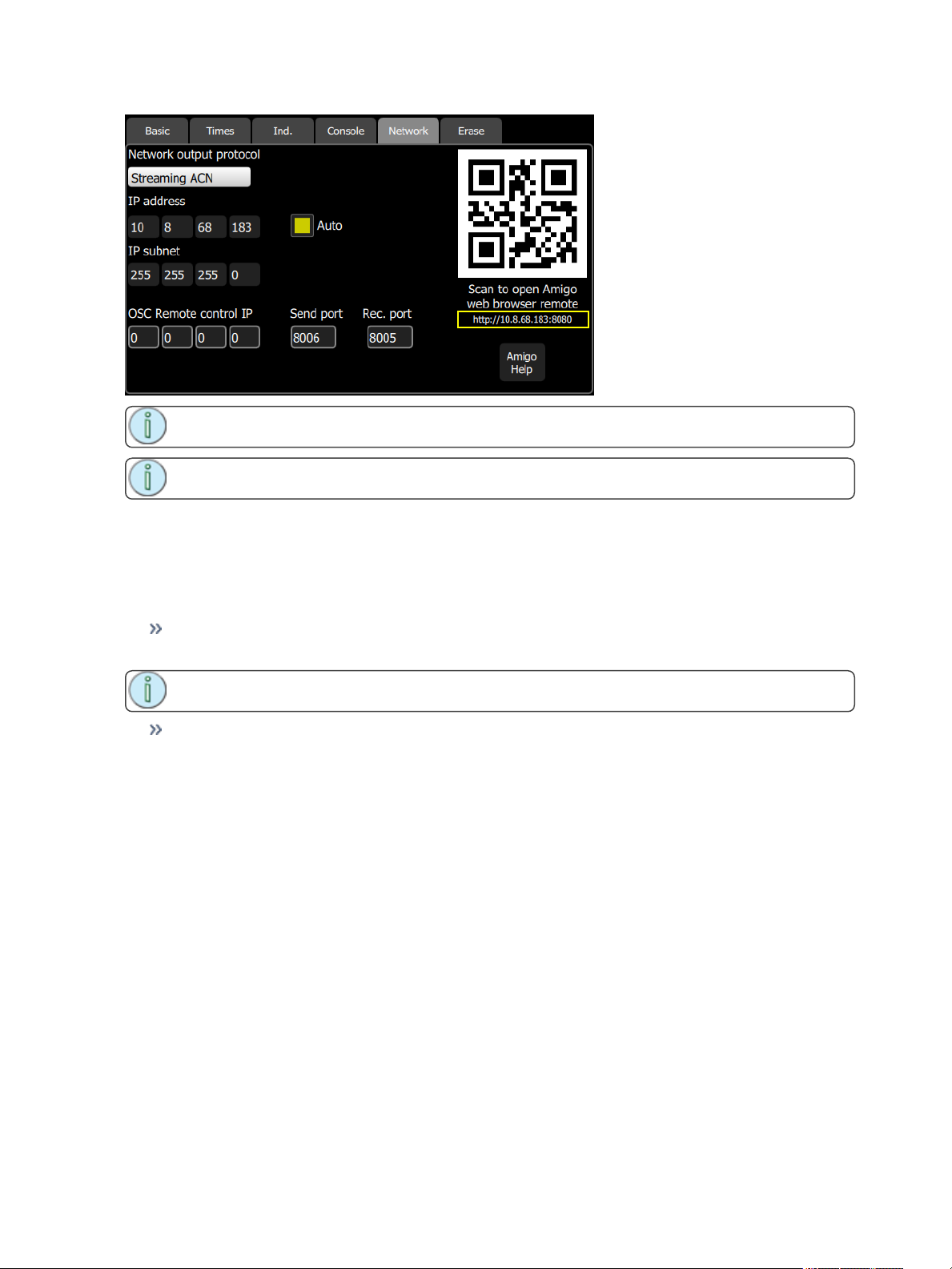
Note: If the QR code is not visible, your console is not currently connected to a network.
Note: A QR reader is required for automatic connection with QR code.
1. Open the Setup>Settings>Basic or Setup>Settings>Network tab.
2. Snapshot the QR code. You may need to wait a few moments for a connection be established.
Setting Up Your Computer, Phone, or Tablet
Open the Setup>Settings>Network tab on your ColorSource AVconsole.
If Auto is enabled, then it is recommended that you set your computer, phone, or tablet to be automatic (DHCP) as well.
Note: Auto is enabled by default on your console, and may be on your device as well.
If Auto is disabled, then you will need to manually set the IPaddress in your computer, phone, or tablet to be compatible with your ColorSource AV console
Entering Addresses Manually
1. Find the IP address of the console on the Setup>Settings>Basic or Setup>Settings>Network
tab. This is four sets of numbers separated by periods. For example: 192.168.0.17 (the actual numbers may be different)
2. Connect a computer to the network port, or to a network switch that is connected to the network
port.
3. Make sure the computer is in the same IP address range. The first two sets of IP address digits
need to be the same. If they are not, then the computer will need to be restarted while connected to
the ColorSource console network. The computer should then find an address starting with either 192
or 169. If you are using manual addressing, you must also manually address the computer accordingly.
Connecting To Amigo
1. Open your internet browser. Supported browsers include: Firefox, Chrome, Safari, and Internet
Explorer v11.
2. On the address line, type http:// then the IP address followed by a colon and then the digits 8080.
Example: If the ColorSource IP address is displayed as 169.254.12.48, type:
66 AV Functions
Page 67
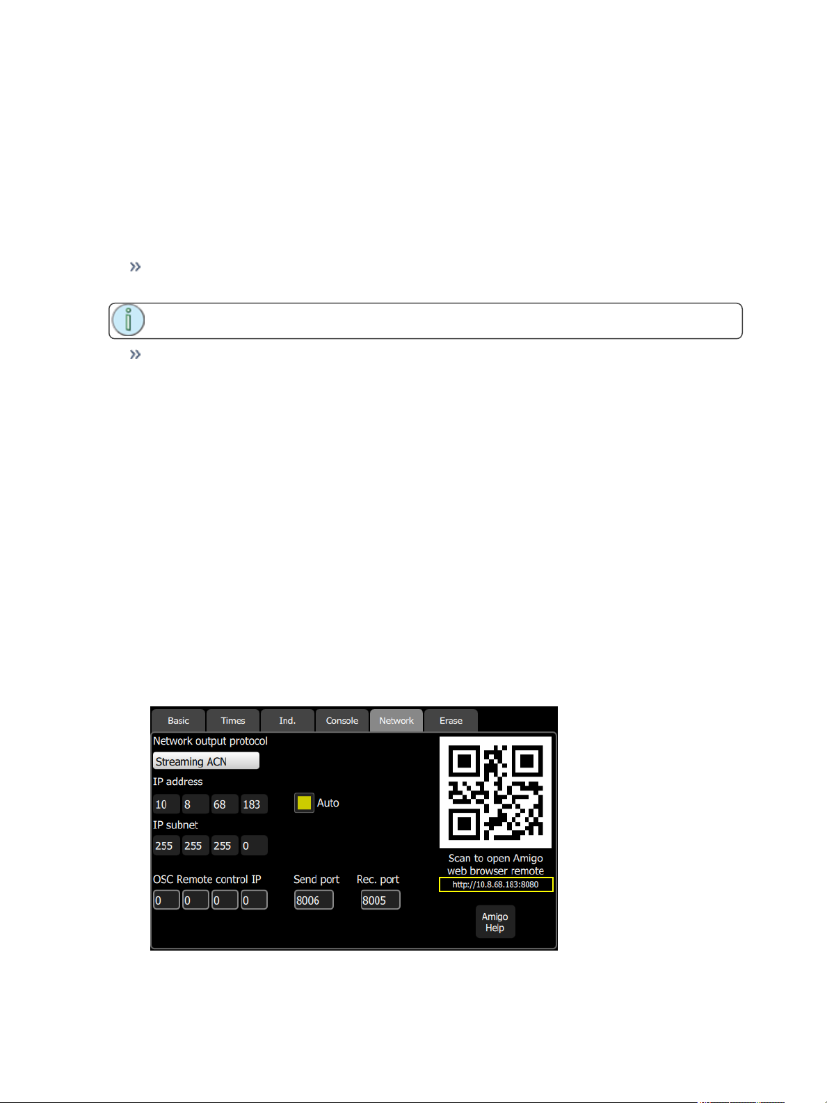
http://169.254.12.48:8080 [Enter]. The full text to type will display under the QR code in the Basic
and Network tabs.
Connecting to the Amigo Remote Web Browser by Cable
To operate your ColorSource AV console from a web browser on a wired network, please follow these
steps:
Setting Up Your Computer, Phone, or Tablet
Open the Setup>Settings>Network tab on your ColorSource AVconsole.
If Auto is enabled, then it is recommended that you set your computer, phone, or tablet to be automatic (DHCP) as well.
Note: Auto is enabled by default on your console, and may be on your device as well.
If Auto is disabled, then you will need to manually set the IPaddress in your computer, phone, or tablet to be compatible with your ColorSource AV console
Entering Addresses Manually
1. Find the IP address of the console on the Setup>Settings>Basic or Setup>Settings>Network
tab. This is four sets of numbers separated by periods. For example: 192.168.0.17 (the actual numbers may be different)
2. Connect a computer to the network port, or to a network switch that is connected to the network
port.
3. Make sure the computer is in the same IP address range. The first two sets of IP address digits
need to be the same. If they are not, then the computer will need to be restarted while connected to
the ColorSource console network. It should find an address starting with either 192 or 169. If you are
using manual addressing, you must also manually address the computer accordingly.
Connecting To Amigo
1. Open your internet browser. Supported browsers include: Firefox, Chrome, Safari, and Internet
Explorer v11.
2. On the address line, type http:// then the IP address followed by a colon and then the digits 8080.
Example: If the ColorSource IP address is displayed as 169.254.12.48, type:
http://169.254.12.48:8080 [Enter]. The full text to type will display under the QR code in the Basic
and Network tabs.
AV Functions 67
Page 68
Note: If the QR code is not visible, your console is not currently connected to a network.
Note: To use a wireless device, you must install a WiFi access point on the network connected
to the console.
Using Help with the Remote Web Browser
The help tab in the remote web browser follows the functions being operated on your ColorSource AV console.
Each time a function is being used, the help page will change to show the help topic for that function.
Note: You do not need to press Help on the console to show help in the browser.
68 AV Functions
Page 69
System Settings and Setup
This section covers the system settings and setup options for your ColorSource console.
The following topics are covered:
Setup 69
Settings 69
Settings: Basic 69
Settings: Times 70
Settings: Independents 71
Settings: Console 71
Settings: Network 72
Settings: Erase 73
Setup
Contains functions used in the setup of the console:
Patch
Settings
Files
Settings
All internal settings and default values are setup here.
Settings are arranged in tabs of related items:
Basic: Operating modes, language, stage map zones, auto-select channel on fader move, and about
console information.
Times: Times for clear, default cue, and default move.
Independents: Independents setup and patching.
Console: Custom setup of console buttons, external monitor, and DMX speed.
Network: Custom setup of your console's network, including network output protocol, OSC set-
tings, and Amigo.
Erase: Erase operations.
Settings: Basic
From this tab you can set the operating mode and language, show zones on the stage map, and select the
fader behavior to auto-select channels.
System Settings and Setup 69
Page 70
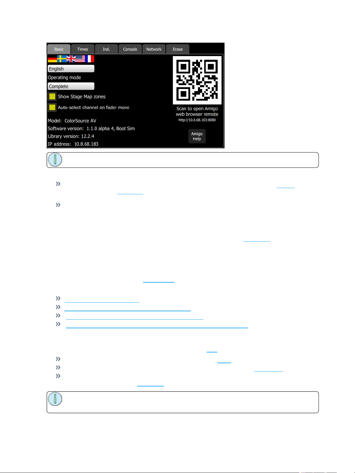
Note: If the QR code is not visible, your console is not currently connected to a network.
Choose the operating mode:
Simple Mode: Simple mode offers a very basic set of lighting controls. There is no cue list, no fader
paging and only four playbacks. Simple mode is ideal for setting up a few static lighting states
without needing any training or deep knowledge of lighting control.
Complete Mode: Complete mode offer the whole set of functions and is suited to trained users and
experienced lighting professionals.
Choose the operating language. Current options are English, French, German, Japanese, Italian, Russian,
and Spanish.
Show stage map zones, when selected, will show the stage map zones. See stage map for more inform-
ation.
Behavior of faders to auto-select channels on move can be disabled here.
The hardware model, current software version, personality library version, and IP address are also displayed on this tab.
You can change the IP address is the Network tab under Settings.
For information about using Amigo:
Amigo Remote Web Browser
Using Help with the Amigo Remote Web Browser
Connecting the Amigo Remote Web Browser via WiFi
Connecting Amigo Remote Web Browser via Cable to a Wired Network
Settings: Times
Sets the following times used as default settings for Clear and Cue programming:
Clear Time: Sets the fade time for clearing channels on the Clear button.
Default Cue Time: The default time for In-fade and Out-Fade in Cues and Sequences.
Default Move Time: The time for parameters to move to new values during move dark and when
picking preset values on the Parameter screen.
Note: Move Dark happens automatically for cue playback and ensures that lights will be moved
to their correct position before the cue in which they appear is played.
70 System Settings and Setup
Page 71
Settings: Independents
Setup for the two independent control channels.
Independents may be used to control lights, for instance the house lights, or accessories and small
machines such as smoke machines or mirror balls.
In this tab, the following settings for independents can be set:
Universe and DMX - an independent can be assigned to a DMX address on a given universe.
Level - sets the on level for the independent.
Bump - sets the bump button operation to a momentary bump or an on-off toggle.
Blackout - sets whether the independent is included or excluded from blackout.
Settings: Console
Setup of the console and its buttons and faders can be done on this tab.
You can adjust the DMX speed. You should choose the fastest setting that works correctly with all your
equipment, normally with modern devices this should be Max or Fast.
You can adjust the backlight for the touchscreen and the brightness of the buttons. 1 is the dimmest setting
and 7 is the brightest.
You can enable an external monitor connected via the HDMI video port. When enabled, you can configure
the video mode to either 1920x1080p-60 or 640x480p-60.
Note: Enabling an external monitor will disable video toy and image playback.
You can assign the five right-most buttons beneath the screen to the following functions:
None
Audio Mute
Back
Blackout
Color
Cue List
Effects
GO
Ind 1
Ind 2
Keypad
Media
Media Pause
Pause
Parameter
Playback Toy
Quick Select
S2L Lights
S2L VideoToy
Speed Clear
Stage Map
System Settings and Setup 71
Page 72
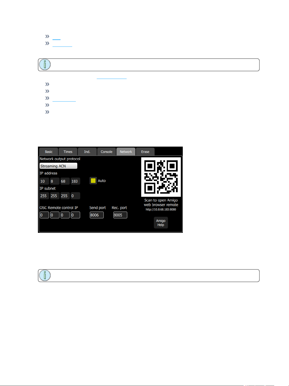
Tap
Video Off
These buttons default to Color, Cue List, Back, Pause, GO.
Note: The left-hand button cannot be re-assigned and always selects the Stage Map display.
You can also assign the four master faders above the screen to the following functions:
Volume
Bumps
Crossfader
Cues
Playbacks
These buttons default to Volume, Playbacks, Cues, and Crossfader.
Settings: Network
From this tab you can configure the network for your ColorSource AVconsole.
Choose the network output protocol. Current options are Streaming ACN(sACN) or ArtNet.
When Auto is enabled (the box will be yellow), the IPaddress and subnet will automatically be set via a
DHCP server. This is the recommended setting.
If Auto is disabled, you will need to set the desired IP address and subnet. After you set those, press the
Activate button to apply your changes.
Note: If the QR code is not visible, your console is not currently connected to a network.
72 System Settings and Setup
Page 73
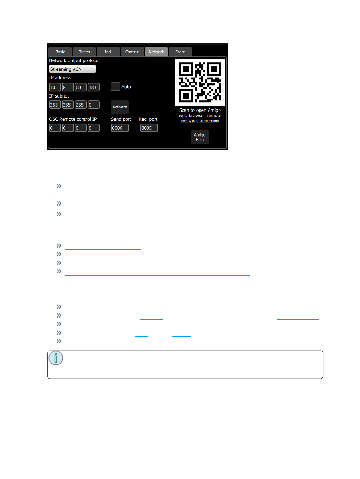
Open Sound Control (OSC)
OSC is a protocol that uses network communication (wired or wireless) to communicate between various
audio, video, and lighting devices, and other devices, such as tablets for remote control of your console.
OSCRemote control IP- sets the IPaddress of the device that the console will be sending
OSCoutput to or receiving OSC input from.
OSCSend Port - sets the port address that the console will send OSCstrings to.
OSCReceive Port - sets the port address that the console will receive OSCstrings from.
For a list of supported OSCcommands, please see OSC Commands (on page63).
For information about using Amigo:
Amigo Remote Web Browser
Using Help with the Amigo Remote Web Browser
Connecting the Amigo Remote Web Browser via WiFi
Connecting Amigo Remote Web Browser via Cable to a Wired Network
Settings: Erase
The following erase operations are available in this tab:
All: Erases all of the show data.
Memories: Erases all of the playback memories. To erase just one playback, use Erase Playback.
Sequences: Erases all of the sequences.
Cue List: Erases all of the cues from the cue list.
Patch: Erases all of the patch.
Note: Erasing an item removes it from the show permanently. Erasure is not the same as clear-
ing a cue or playback. A cleared item can be run again, an erased item cannot be run once
removed.
System Settings and Setup 73
Page 74

74 System Settings and Setup
Page 75
Showfile Management
This section explains how to create, save, open, delete, import, and export show files. Software upgrades
and creating a default show file are also covered.
Files
All filing operations:
New
Open
Save
Save As
Show files:
Save as default
Remove default
Delete
Import
Export
Media:
Import USB
Import Show
Delete media
Advanced:
Update Firmware
Install Extras
Export Logs
Caution: All data is stored internally in non-volatile memory. Do not switch off the power until
any pending save operation is completed, or you may lose data. It is strongly advised that you
make periodic backups of important data to an external memory stick using the Export function.
File, New
Start a new show by going to Setup>Files>New.
Note: You will be warned that this action will clear the memory. Select Yes to clear memory
and start a new show, or No to cancel.
The new show will be based on the template default show, which is customizable.
File, Open
Open an existing show file by going to Setup>Files>Open.
Note: Show files must be in the console's internal storage before they can be opened here. If
the file is located on a memory stick, you will need to use import first.
ShowfileManagement 75
Page 76

File, Save
Save the show by going to Setup>Files>Save.
The show will be saved with the name you last gave it. If you have not yet saved the show with a name,
you will be prompted to enter a show file name.
Caution: All data is stored internally in non-volatile memory. Do not switch off the power until
any pending save operation is completed, or you may lose data. It is strongly advised that you
make periodic backups of important data to an external memory stick using the export function.
File, Save As
Save the show by going to Setup>Files>Save As. The show will be saved with the name you enter.
Note: The difference between Save and Save As is you will always be asked to name the show
file when you use Save As.
Caution: All data is stored internally in non-volatile memory. Do not switch off the power until
any pending save operation is completed, or you may lose data. It is strongly advised that you
make periodic backups of important data to an external memory stick using the Export function.
File, Import
Use of Media Notice
Import an existing show file by going to Setup>Files>Shows>Import.
Note: Show files must be saved on a memory stick, in a folder named "Shows" in the root dir-
ectory.
When the Import button is pressed, the following screen will display showing the available show files.
Select the desired file, and then press Accept. If you want to leave this display without importing, press
Cancel.
File, Export
Export the current show file by going to Setup>Files>Shows>Export.
Use of Media Notice
Note: Show files will be saved onto a memory stick, in a folder named "Shows" in the root dir-
ectory.
76 ShowfileManagement
Page 77
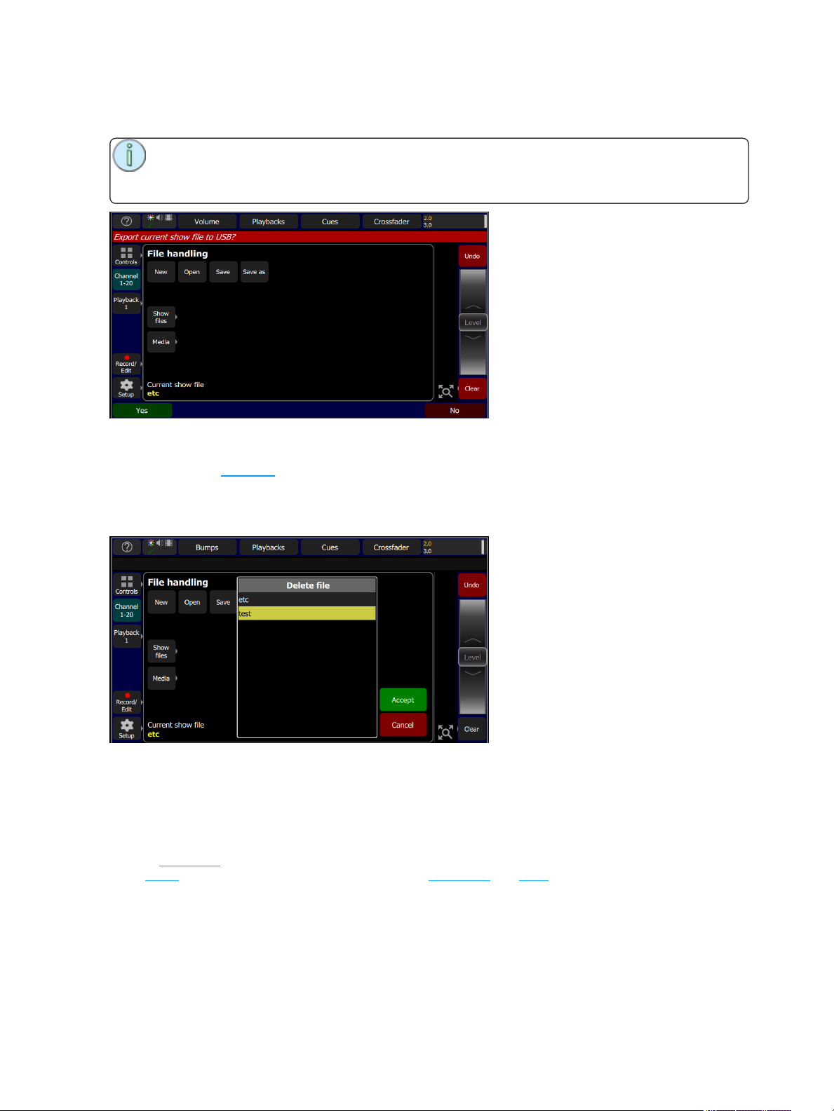
When the Export button is pressed, the following screen will display. Press Yes to export. If you want to
leave this display without exporting, press No.
Note: Exported shows contain all the media used in the show. If there is a large amount of
image or audio clip content, the save may take some time to complete. Please ensure the USB
drive has sufficient free space.
File, Delete
Delete an existing show file off the console by going to Setup>Files>Shows>Delete.
When the Delete button is pressed, the following screen will display showing the available show files.
Select the desired file, and then press Accept. If you want to leave this display without deleting, press
Cancel.
Files, Show files
You can open and save shows by going to Setup>Files
Shows are saved internally with all content, including lighting,effects, and media.
Pressing the Show files button gives you the default show options.
When a new show is started, it will be based on the default show template, which you may define to con-
tain a patch or part-patch, some show data, including playbacks and cues, or nothing as required.
If your lighting rig is fixed and usually the same set of equipment set to the same addresses, the default
show will help you save patching and setup time. If you prefer to start with a blank state each time, no
patch and no data, then you can save an empty default show.
ShowfileManagement 77
Page 78
Functions
Save As Default
Remove Default Show
Delete
Import
Export
Caution: All data is stored internally in non-volatile memory. Do not switch off the power until
any pending save operation is completed, or you may lose data. It is strongly advised that you
make periodic backups of important data to an external memory stick using the export function.
Save As Default
The current show will be saved as the default to be used each time Setup> File > New is selected. Typ-
ically this will include a standard patch, but may also include any other show elements, for example, playbacks for operating house lights or other standard functions.
Caution: All data is stored internally in non-volatile memory. Do not switch off the power until
any pending save operation is completed, or you may lose data. It is strongly advised that you
make periodic backups of important data to an external memory stick using the export function.
Remove Default Show
The Default show is removed to a complete blank state with no patch or content at all.
Selecting File > New will start the console with no programmed content at all.
Caution: All data is stored internally in non-volatile memory. Do not switch off the power until
any pending save operation is completed, or you may lose data. It is strongly advised that you
make periodic backups of important data to an external memory stick using the export function.
Files, Media
Use of Media Notice
All media used in a show must be stored locally inside the console.
Media may be imported from an external memory stick.
Only one copy of each media file is needed even if it is used in several shows. However, when a show is
exported to a memory stick, all the included media is also included in the export.
Supported File Types
Audio: mp3, aac and wav files (44.1kHz sample rate, 4GB maximum file size)
Image: jpg, png, tiff, and bmp files (1280 x 720 max size)
Note: It is recommended not to use the same name for different items of media. If the media is
exported and then re-imported to the same console or another console, this would cause a local
copy to be over-written.
78 ShowfileManagement
Page 79
Functions
Import USB: imports media from an external memory stick. Files must be in a folder called Import
in the root of the USB stick.
Import Show: imports media from another show file.
Delete Media: deletes selected media from your console.
Caution: All data is stored internally in non-volatile memory. Do not switch off the power until
any pending save operation is completed, or you may lose data. It is strongly advised that you
make periodic backups of important data to an external memory stick using the export function.
Import Media
Importing Audio and Image clips.
Use of Media Notice
All media used in a show must be stored locally inside the console.
Media may be imported from an external memory stick.
Only one copy of each media file is needed even if it is used in several shows. However, when a show is
exported to a memory stick, all the included media is also included in the export.
Supported file types
Audio: mp3, aac and wav files (44.1kHz sample rate, 4GB maximum file size)
Image: jpg, png, tiff, and bmp files (1280 x 720 max size)
Note: It is recommended not to use the same name for different items of media. If the media is
exported and then re-imported to the same console or another console, this would cause a local
copy to be over-written.
Functions
Import USB: imports media. The files must be in folder named Import on a FAT32 formatted USB
drive.
Import Show: imports media from another show file.
Delete Media: deletes selected media from your console.
Caution: All data is stored internally in non-volatile memory. Do not switch off the power until
any pending save operation is completed, or you may lose data. It is strongly advised that you
make periodic backups of important data to an external memory stick using the export function.
Delete Media
Delete Audio and Image files saved to your ColorSource AV console by going to Setup>Files>Media>Delete media.
When the Delete media button is pressed, a screen will display showing the available media files. Select
the desired file, and then press Accept. If you want to leave this display without deleting, press Cancel.
ShowfileManagement 79
Page 80
Files, Advanced
Functions
Update firmware - updates the console's main operating software.
Install Extras - add or replace data files, such as new device personalities, help texts or languages.
Export Logs - exports the console's log files to a USB drive.
Caution: All data is stored internally in non-volatile memory. Do not switch off the power until
any pending save operation is completed, or you may lose data. It is strongly advised that you
make periodic backups of important data to an external memory stick using the export function.
Update Firmware
The main operating software can be updated here. The software must be obtained from ETC and placed in
the root of the USB drive. Please make sure the software file is not inside any other folder or subdirectory,
as this will hide it from ColorSource's update function.
The file name will be in this format: ETC_CS_#.#.#.#.#.#.fw (the software version will replace #.#.#.#.#.#).
Caution: The update process may take a few minutes. Do not shutdown the console until the
process has finished. You will be prompted to shutdown the console and restart after the update.
Install Extras
Data and content used by the console may be imported here.
This includes new device personality libraries, new help texts, language revisions, additions, and other
internal features as they become available.
The files you wish to import must be obtained from ETC and placed in the root of the USB drive. The files
will be named with the suffix .cspkg.
Note: You cannot update the main operating software here, only support files. To update the
main software version, you will need to use the Update firmware button.
Note: Fixture profiles are not loaded from this display. Please see Loading a Fixture Profile for
instructions.
Export Logs
Exports the console's log files to a USB drive. Tap Yes to export or No to cancel.
The file name will be in this format: ColorSource_Logs_#.tar.gz.
Installing Language Packs on a ColorSource Console
Any available language packs can be downloaded from the ETC website (www.etcconnect.com) as .zip
files.
1. Once downloaded, extract your file.
2. Place it onto the root directory of a USB drive. The file name will end with .cspkg.
3. Plug the USB drive into the USB port of your console.
4. On your console, go to Setup>Files>Advanced>Install Extras.
5. A list will appear that shows the files on your USB drive. Select the appropriate language file to
install.
80 ShowfileManagement
Page 81

ShowfileManagement 81
Page 82

Corporate Headquartersn Middleton, WI, USA n Tel + 608 831 4116 n Service:(Americas) [email protected]
London, UK n Tel +44 (0)20 8896 1000 n Servi ce: (UK) [email protected]
Rome, IT n Tel +39 (06) 32 111 683 n Service: [email protected]
Holzkirchen, DEnTel +49 (80 24) 47 00-0nServi ce: (DE) techserv-hoki@etcconnect. com
Hong KongnTel +852 2799 1220n(Asia) [email protected]
Web: www.etcconnect.comnCopyright 2016 © Electronic Theatre Controls, Inc.
Product i nformation and s pecifications subject to change. ETC intends t his document to be provi ded in its entirety.
7225M1210-1.1.0 Rev A n Released 2016-12 n
n
 Loading...