

Page 1

2012-11-14
EN_Englisch
Operation
Log Boiler
20-60 kW
Page 2

2
www.eta.co.at
Contents
Conditions for warranty, guarantee, liability ........ 4
Emission measurement ...................................6
Chimney renovation .......................................7
Boiler functionality ........................................8
Start-up ..................................................... 10
Checking water pressure, suitable fuel ................ 10
Correct quantity of wood ................................ 11
Water pressure, heating lines, cleaning lever ........ 12
Charging status of buffer storage tank ................ 13
Adding wood .............................................. 14
Ignition, closing doors ................................... 15
Closing ignition and insulation doors ................. 16
Adding fuel ................................................. 17
Safety ........................................................ 18
Safety devices to prevent overheating ................18
Maintenance ............................................... 20
Overview of activities .................................... 20
Each time the boiler is filled ............................ 21
Every 1 - 2 weeks ........................................ 22
Annually .................................................... 24
Every 3 years ............................................... 28
Approval, antifreeze, pressure equalisation, venting
32
Softened water, safety valve .......................... 33
Return riser and safety devices ....................... 34
Minimum heat consumption, buffer storage tank 35
Split wood will dry out in just one summer .........36
Heating value of wood .................................. 37
User interface .............................................. 38
Adjusting the date and time ............................ 38
Changing the language .................................. 39
Changing function block names ........................40
Alarm, error, warning, message ........................41
Opening the text menu .................................. 42
Buffer [Buffer] ............................................. 46
Overview, buttons, functions ........................... 46
Buffer with solar .......................................... 47
Combination tank with solar ...........................48
"Buffer bottom max." for solar heating systems .... 49
Heating circuit [HC1] ..................................... 50
Meanings of symbols
Important NOTICES for operation.
CAUTION: Failure to observe these notices can
result in property damage.
STOP: Failure to observe these notices can result in
personal injury.
Overview, buttons and functions ...................... 50
Operating states ........................................... 52
Setting heating time slots ............................... 54
The heating curve ......................................... 56
"Day Heating threshold" and "Night Heating
threshold" .................................................. 57
Adjusting the heating curve ............................ 58
Setting the "enable temperature" .....................60
Adjusting the "Set-back" ................................ 61
Service and maintenance records ..................... 62
Page 3

3
2012-11
Preface
SH Operation
Dear Customer,
We are delighted to count you among our
customers.
To ensure satisfactory operation of your new boiler,
you need to know how to operate, clean and
maintain it. This manual contains information and
advice on much more than just the boiler itself.
Warranty and guarantee
You should also read the "Conditions for warranty,
guarantee, liability" (page 4) carefully. As a
rule, these conditions will be satisfied by a professional heating technician. Nevertheless, inform the
technician of our warranty conditions. All of the
requirements we impose are intended to prevent
damage that neither you nor we wish to occur.
Information worth knowing in this regard can also
be found starting on page 32.
Optimum use of the control systems installed in
our boilers
There are two different access levels for the control
system:
At the CUSTOMER level, you can adjust the control
system to your wishes and needs without any risk
of altering the system configuration set by the
heating system expert.
Only your technician or a customer service
employee should change settings at the SERVICE
level. Before making any adjustments to these
settings yourself, it is essential that you consult an
expert.
Read this manual
carefully before starting up the system. This is the
only way to ensure that you can operate your new
boiler efficiently and with minimum environmental impact.
Take advantage of the knowledge and skills of an
expert.
Only allow an expert to assemble, install and
commission the equipment and make the basic
boiler settings. Insist on receiving an explanation
and training on how your new boiler functions and
how to operate and maintain it.
Extended warranty for commissioning performed
by an authorised partner company
If your newly installed boiler is commissioned
by an authorised partner company or one of our
customer service employees, we offer an extended
warranty. Refer to our warranty conditions in
effect at the time of purchase.
Service agreement
You can ensure the best care for your heating
system by taking out a service agreement with one
of our certified heating system contractors or our
own customer service.
Page 4

4
www.eta.co.at
Conditions for warranty, guarantee, liability
We can only guarantee and accept liability for the
function of our boiler if it is properly installed and
operated.
Requirement for warranty, guarantee and liability
is that this boiler be used in accordance with its
intended purpose, only for heating and hot
water supply with no more than 2,000 fullload hours annually, and, in particular, that the
following general conditions be observed during
installation and operation:
For set-up, a dry room is required. In particular,
only condensation dryers may be used as clothes
dryers in the same room.
Local building and fire protection regulations must
be observed.
The log wood boiler is suitable for use with
air-dried split logs with no more than 20%
water content and wood briquettes. Use with
unsuitable fuels, especially refuse, coal and coke,
and also wet wood, is not permitted.
The combustion air must be free of aggressive
substances such as chlorine and fluorine
from solvents, cleaning agents, adhesives and
propellants, or ammonia from cleaning agents,
to prevent corrosion of the boiler and chimney.
Water is the intended heat-transfer medium. For
special anti-frost requirements, up to 30% glycol
may be added. Softened water is required for
the initial fill-up of the heating system and for
refilling after repairs. For the initial fill-up, the
value of 20,000 lt°dH for the system volume in
litres multiplied by the hardness (in degrees of
German hardness) may not be exceeded. The
pH value should be set between 8 and 9.
Addition of hard water should be minimised to
limit limescale build-up in the boiler. Set enough
shut-off valves to avoid bleeding large amounts of
water during repairs. Any leaks in the system must
be repaired at once.
Ensure a minimum return temperature of 60°C
to the boiler.
A safety valve (3 bar) as protection against excess
pressure and a thermal relief valve (95°C) to
protect against overheating must be installed by
the contractor.
To protect against air suction if the system cools
off, an expert must provide a sufficiently large
expansion tank or a pressure maintenance
system. Sufficient air venting must also be
ensured. Open expansion tanks or underfloor
heating with permeable piping also have a
high air intake, resulting in above-average boiler
corrosion. Corrosion damage to the boiler due to
improper air venting or high air intake is excluded
from warranty, guarantee and liability.
Operation at lower power than the lowest power
specified on the type plate is not permitted.
Only components provided by us may be used
for expansion of the control system, except for
commonly used units such as thermostats.
Cleaning and maintenance are required as
specified in the user manual.
Repairs are only permitted with spare parts
provided by us. The only exceptions are common
standardised parts such as electrical fuses or
fastening materials, as long as they possess
the required features and do not restrict the
functionality of the system.
Page 5

5
2012-11
Conditions for warranty, guarantee, liability
SH Operation
Subject to technical alterations
We reserve the right to make technical
modifications without notice. Printing and
typesetting errors or changes of any kind made
in the interim are not cause for claims. Individual
configurations depicted or described here are only
optionally available. In the event of contradictions
between individual documents regarding delivery
scope, the information in our current price list
applies.
The installing contractor is liable for proper
installation according to the boiler's installation
instructions and the relevant rules and safety
regulations. If you as customer have installed
the heating system partly or entirely without
relevant training and in particular without
up-to-date practical experience, without having
the installation checked by a trained and
responsible expert, we exclude defects in our
delivery and consequential damages resulting
from this cause from our warranty, guarantee and
liability.
For repair of defects carried out by the
customer or by third parties, ETA only bears the
costs or remains obligated by warranty if this work
was approved in advance by the customer service
of ETA Heiztechnik GmbH.
Page 6
6
www.eta.co.at
Emission measurement
Why measure emissions?
It is a requirement for the carbon monoxide (CO)
emissions of every boiler to be measured periodically. In Germany, this periodical measurement
must also include a dust measurement.
There are several aspects of this that could go
wrong, resulting in incorrect measurements even
though the boiler fully and consistently complies
with these limits when operating in accordance
with the relevant standards.
Boiler and flue tube must be cleaned thoroughly
3 days before measurement
The chimney sweep will contact the owner of
the boiler when the measurement is due to take
place. The boiler and the flue tube must be cleaned
thoroughly 3 days before the measurement takes
place. The remaining charcoal stays in the fuel
chamber.
Heat up the boiler after cleaning
After cleaning, the boiler must be heated up again.
This allows dust that was stirred up during cleaning
to settle.
Under no circumstances clean the boiler and flue
tube on the day of the measurement!
Cleaning on the day of measurement should be
avoided as the chimney sweep's measuring probe
would measure the unsettled dust, resulting in a
falsely high dust reading.
The buffer must be empty at the start of the
measurement
The boiler and the buffer should be shut down
before the measurement. This is best done the
night before to prevent the boiler from switching
to partial load during the emission measurement.
Use half-metre logs for the emission
measurement
For the emission measurement, split half-metre
logs are to be used, stacked as tightly as possible
in the boiler (no round logs). The fuel chamber
should be filled as full as possible and the burnthrough openings on the grate must remain free.
Heat up boiler 1-2 hours before measurement
Heat up the boiler 1-2 hours before the chimney
sweep's arrival.
Ensure sufficient heat consumption
Open all the radiator valves and turn the radiator
thermostats to maximum.
Close doors at 100°C exhaust gas temperature
At 100°C exhaust gas temperature, close the
ignition door and the insulation door. Do not
open any doors before and during the emission
measurement. Also, do not stoke the fire.
Switch boiler to emission measuring mode
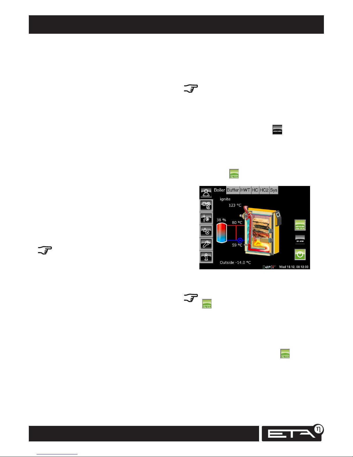
In the boiler overview screen, tap . This
switches the boiler into emission measurement
mode and operates it for 30 minutes at full load.
The control system ensures that sufficient heat is
channelled to the buffer, the heating circuits and
the hot water tank. The button shines green and
a countdown for the emission measurement
mode is displayed.
Wait 10 minutes, then perform emission
measurement
Once emission measuring mode has been activated
( ), wait for 10 minutes until the boiler has
reached the required operating temperature and
stable combustion is ensured. Then carry out the
emission measurement.
After the measurement
After the measurement, emission measurement
mode can be deactivated by pressing again. If
this button is not pressed, the boiler will automatically switch back to normal mode after 30
minutes.
Page 7

7
2012-11
Chimney renovation
SH Operation
Chimney renovation
With its controlled induced-draught fan and
adjustable minimum exhaust gas temperature,
your new boiler will largely adjust to existing flues
without the need for any special measures. Nevertheless, you should have the suitability of your flue
checked by a chimney sweep or chimney builder.
If the draught exceeds 30 Pa in very tall flues, a
draught-regulating damper is required.
Modern heating boilers are more efficient than
older ones and thus produce smaller amounts of
exhaust gas at considerably lower exhaust gas
temperatures.
Flues with "too large a cross-section" in particular
are no longer heated adequately. The moisture
contained in the exhaust gases condenses in the
flue and leads to very slow but inexorable destruction of old masonry chimneys.
Furthermore, if the diameter of the flue is too large,
the exit velocity and temperature are too low. The
exhaust gas does not have enough energy to rise
and, in extreme cases, the smoke can flow down
the roof.
If your flue does not have a water-resistant liner or
its diameter is too large, it will need to be renovated with the addition of a moisture-insensitive
inner lining. If the existing flue cross-section is
adequate, a ceramic liner that is also resistant to
chimney fires is preferable to a stainless steel liner
when burning wood.
In the case of short flues that are not resistant to
moisture, it may suffice to raise the lower limit
for the exhaust gas temperature to 180°C in the
boiler's control system. In addition an auxiliary
air damper will help to keep the flue dry. If these
measures are deemed satisfactory, the flue should
be inspected to check whether it actually remains
dry. This is best discussed with the chimney sweep.
Also keep in mind that chimneys have a limited
service life. Timely renovation before the chimney
wall has been destroyed can be performed quickly
and easily by inserting a tube. But if the flue gas
condensates have penetrated the mortar joints,
then the entire flue must be dismantled and
rebuilt.
Page 8

8
www.eta.co.at
1
2
3
4
5
6
7
Boiler functionality
Wood gasification
Before wood can burn, it must first be converted
into gas by application of heat. From 100°C, the
moisture contained in the wood is driven off. From
200°C, the process of decomposition into 20%
charcoal and 80% wood gas, a mixture of carbon
dioxide, carbon monoxide, hydrogen, methane,
methanol, various phenols, acetone and acetic
acid begins. Gas is released from a temperature of
400°C. However, a temperature of at least 900°C
is required to fully break down phenols (wood tar)
into combustible carbon, carbon monoxide and
hydrogen; 1100°C is better. In addition to a high
temperature, breaking down complex compounds
into wood gas also requires time; this explains why
the gas flame of a wood fire lasts so long.
Large wood supply in the fuel chamber
At the base of the stack of wood in the fuel
chamber, a small gasification fire is maintained
through a controlled flow of air (primary air) (1).
The boiler's control system regulates the output
of the gasification fire via the flow of primary air
(2). The wood gas is drawn downwards into a hot
combustion chamber. This prevents the stack of
wood in the fuel chamber from undergoing uncontrolled gasification and starting to burn and makes
it possible to have a boiler with a large supply of
wood that burns slowly for a long time.
Mixing nozzle and complete turbulence
A mixing nozzle (3) is located between the fuel
chamber and the combustion chamber. Here
preheated combustion air (secondary air) is mixed
with the wood gas. The flame exiting the mixing
nozzle hits the hot bottom of the combustion
chamber with high velocity and experiences
further turbulence (4), ensuring that every bit
of combustible gas finds sufficient oxygen for
complete burnout.
Complete burnout in the glow zone
To achieve uncooled combustion at high temperatures, the patented glow-zone combustion
chamber is made from refractory brick and is also
thermally insulated (5). In this glow zone, the
flame has enough time at temperatures between
900°C and 1100°C to break down and burn the
very last of the resistant carbon rings (phenols)
from the lignin in the wood. This enables the log
boiler to go below the limit of 100 mg of carbon
monoxide in the exhaust gas per MJ of output.
Page 9
9
2012-11
Boiler functionality
SH Operation
Induced-draught adjusts to the flue
Thanks to the induced draught concept, the entire
interior of the boiler is under a negative pressure.
This means that no smoke or low-temperature
carbonisation gases can escape from the boiler
regardless of the phase of operation. The induceddraught fan accommodates every flue, even those
with small cross-sections. Speed control and continuously adjustable dampers for combustion air
make draught limiters in the flue virtually unnecessary. Setting a minimum exhaust gas temperature prevents condensate formation in masonry
flues and allows the low-temperature capability of
modern flues to be fully utilised.
Turbulent heat exchanger with simple cleaning
The hot gas only enters the cold section of the
boiler following complete combustion. Once in the
cold section, it transfers its heat to the boiler water,
first while smoothly flowing through a long ash
collection duct (7) and then turbulently through
heat exchanger tubes equipped with turbulators.
The more turbulent the flow, the more the gas
comes into contact with the tube walls, thus
ensuring maximum transfer of heat to the boiler
water. This ensures low exhaust gas temperatures
and high efficiency. Pulling the cleaning lever
about 10 times prior to opening the boiler to refill
with fuel moves the turbulators up and down in
the heat exchanger tubes. The resulting fly ash
drops into the ash collecting duct, leaving the heat
exchanger clean.
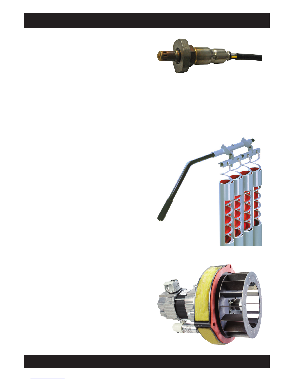
Optimum fuel efficiency with lambda control
Gasification of the wood (output) can be controlled
via the flow of primary air. Through use of the
lambda-controlled secondary air (6), combustion
is kept clean and highly efficient. A lack of air
means there is not enough oxygen for complete
combustion. On the other hand, too much air
also results in incomplete combustion as it cools
the fire. Below 700°C, not all of the wood gas is
burned. Too much air also pulls unused heat out
of the boiler. The lambda probe ensures optimum
combustion and maximum fuel utilisation not only
with selected wood on the test stand, but also in
everyday operation.
Page 10
10
www.eta.co.at
Checking water pressure, suitable fuel Star t-up
Suitable fuel
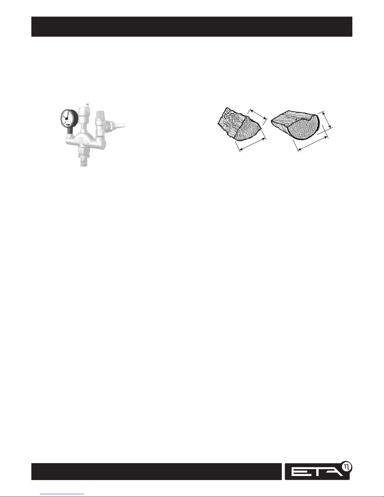
The firewood must be air-dry, i.e. it must have
dried for at least one year and have a water
content under 20%. We recommend using halfmetre split logs with an average diameter of 10
cm.
7 - 9 cm
13 - 16 cm
8 - 10 cm
12 - 15 cm
Boards may only be added between the logs and
in no case should they be included in the first layer
as they would block the burn-through opening in
the grate.
Small pieces of firewood may only be used for
heating if added as a minor component to the
primary fuel. The smaller the pieces of firewood,
the less of them should be added.
Wood briquettes measuring 6 cm to 10 cm in
diameter in compliance with ÖNORM M 7135;
Germany: 1.BimSchV 15 July 1988 Fuel Class 4.
Only one oversized log per boiler filling
Only 1 oversized split log or 1 stump can be placed
in the top layer, but no more. Complete burning
may require 2 combustion phases.
Unsuitable fuel
Wet fuel with a moisture content in excess of 20%
may not be burned as it results in condensation
which can lead to corrosion of the boiler's fuel
chamber walls. The following may not be burned:
rubbish, paper and cardboard (only for start-up),
wood dust from sanding, sawdust, wood chips
smaller than thumb-sized, coal and coke, and fuels
generally prohibited by local air quality regulations, such as railway sleepers, plastic-coated
plywood, impregnated wood etc.
Check water pressure
With a log boiler, it is no trouble to glance at the
pressure gauge daily or at least regularly. In houses
with up to three storeys, the water pressure in a
cold system should be between 1 and 2 bar, for a
warm system between 1.5 and 2.5 bar.
The most common defects in a heating system, i.e.
leaks and boiling over, result in a low water alert.
In the event of insufficient volume compensation,
water is released via the safety release valve. Either
the expansion tank is too small, the diaphragm
in the expansion tank is torn or a tap or valve
between the heating system and the expansion
tank was shut unintentionally. In this case, open
the valve or tap, remove the lever or hand wheel
and attach it to the valve with a wire.
Water will generally need to be added after the
radiators have been bled.
Minimum pressure
To establish the minimum pressure for a cold
heating system (especially when the buffer is also
cold from top to bottom), determine the height
of the space requiring heating above the heating
system's pressure gauge and add three metres. The
result is the minimum pressure in metres. Dividing
the metre value by ten gives you the minimum
pressure in bar, as shown on most pressure gauges.
Return temperature at least 60°C
The boiler return temperature should be at least
60°C to prevent corrosive condensation of flue
gases in the heat exchanger. The control system
monitors the return temperature. If the boiler
return temperature is too low, a warning appears
on the display.
Page 11
11
2012-11
Star t-up Correct quantity of wood
SH Operation
Correct quantity of wood
When not much heating is needed only place a
small amount of wood in the boiler
Absorbing all the heat from a boiler fully loaded
with wood would require buffer storage tanks
larger than needed for winter operation and also
larger than those normally installed. When less
heat is required, i.e. for hot water in the summer,
or during the evening shortly before the night
set-back, only load the boiler with the amount of
wood actually needed.
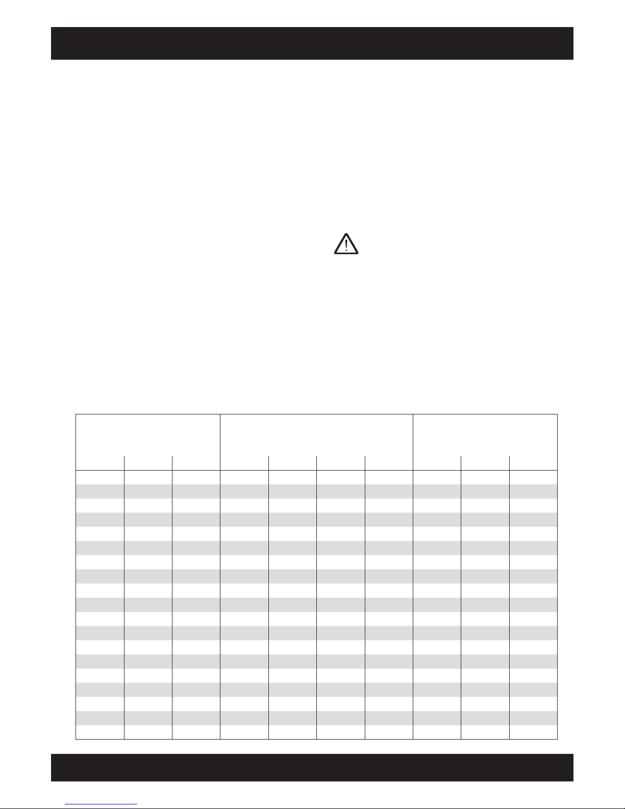
The table below displays the amount of wood
needed for summer operation for different boiler
sizes (= fuel chamber capacity), wood type, buffer
volume and buffer charging status. Bear in mind
that an "buffer top" temperature sensor that is
installed too low reduces the usable volume.
If the living space already needs some heating,
start with the amount of wood in indicated in
the table below. To establish the correct amount,
approach the fully charged buffer state slowly,
adding one or two more logs every heating
cycle. If too much wood is loaded, an emergency
shutdown of the boiler will occur. If the boiler
overheats, the flow of air is stopped. The fire
will go out, but the hot wood will continue to
smoulder for a while and the unburned wood gas
resulting from the lack of air will create tar deposits
in the boiler and flue. This happening once or
twice in an emergency is not a problem. However,
if this situation occurs every day, the boiler's heat
exchanger will become clogged with tar.
Note the energy density of the fuel
The energy content of 50 litres of wood briquettes
corresponds to 100 litres of beech wood or 150
litres of spruce.
Current buffer charging status is shown in
overview
The current buffer charging status in percent is
shown in the boiler [Boiler] and buffer [Buffer]
overviews. The buffer charging status is the
average of the three buffer temperatures (top,
middle, bottom) between 30°C (=0%) and 80°C
(=100%).
SH20, SH30 Buffer charging status SH40, SH50, SH60
Maximum fuel load Buffer size Maximum fuel load
Briquettes Beech Spruce 3,300 l 2,200 l 1,650 l 1,100 l Spruce Beech Briquettes
90% 85% 80% 70%
85% 78% 70% 55%
1/4 80% 70% 60% 40%
1/4 75% 63% 50% 25% 1/4
70% 55% 40% 10%
1/2 65% 48% 30% 0%
60% 40% 20% 1/4 1/8
55% 33% 10%
1/4 1/2 3/4 50% 25% 0% 1/2
45% 18%
40% 10%
Full 35% 0%
30%
3/4 25% 3/4 1/2 1/4
20%
15%
10%
5%
1/2 Full 0% Full
Page 12

12
www.eta.co.at
Water pressure, heating lines, cleaning lever Start-up
Boiler start-up
Check water pressure
Before starting up, check the heating system's
water pressure (see also page 10). In houses
with up to three storeys, the water pressure in a
cold heating system should be between 1 and 2
bar, for a warm system between 1.5 and 2.5 bar.
Open heating lines
If the system is new or has been out of operation
for some time, verify whether the return riser
mixing valve is in "AUTO" position and all
shut-off valves in the heating lines are open.
Keep ball valves completely open to avoid ruining
the seals. Open valves by turning anti-clockwise,
and then turn back 1/4 turn from the fully open
position to relieve pressure on the valve stem.
Operate cleaning lever
With the insulation door still closed, clean the heat
exchanger by operating (10x) the cleaning lever
on the side.
10x
Afterwards, leave the lever pointing towards the
rear of the boiler. Then the turbulators remain in
position in the water-cooled heat exchanger.
Open insulation door, draught fan starts
automatically
When the insulating door is opened, the draught
fan starts automatically and the on/off button
in the boiler overview shines green. The operating
mode changes to "Insulation door open".
Page 13

13
2012-11
Star t-up Buffer charging status
SH Operation
If the draught fan does not start, it has been
deactivated by the safety temperature limiter due
to boiler overheating and a corresponding warning
appears on the display. The safety temperature
limiter can be manually released as soon as the
boiler temperature has fallen below 70°C.
Open fuel chamber door
The draught fan must be running before the
fuel chamber door is opened so that any
combustion gas can be extracted from the fuel
chamber. If the boiler has not safely cooled, no
boiler doors may be opened without an operating
draught fan. A sudden inflow of air in the presence
of smouldering wood may result in an explosion.
Combustion chamber
door
Fuel chamber door
The fuel chamber door is always closed during
both start-up and heating operation. It is
opened only when ash is removed from the boiler.
Check fuel chamber
Use the poker to distribute ashes and charcoal
evenly throughout the fuel chamber. In the panels,
the two upper openings for primary air must
be free. Also, the 3 burn-through openings in
the grate must stay open so that the fire reaches
the combustion chamber during ignition.
Primary air openings
Burn-through openings
Check buffer charging status
Before starting the boiler, check the current buffer
charging status to avoid adding too much
wood. The table on page 11 shows how much
wood should be added. The buffer charging status
is shown in percent values in the boiler overview.
Pay particular attention to the different energy
densities of the fuels.
Page 14
14
www.eta.co.at
Adding wood Start-up
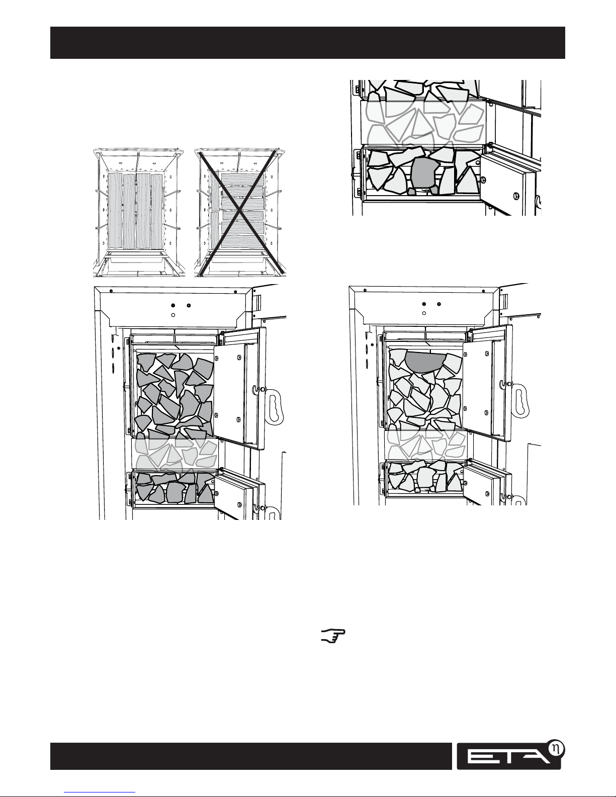
Place logs close together in fuel chamber
Add the required amount of closely spaced logs
to the fuel chamber. Stack the logs instead of
throwing them in at random. Always place the first
layer of logs lengthwise.
Adjust log over burn-through opening
Lift the bottom log above the burn-through
opening with the poker and place pieces of
charcoal (from the fuel chamber) or small pieces
of wood under it so that the burn-through
openings in the grate remain clear. To make
ignition easier, next to the log on the left and
right there should be a small gap separating it
from the neighbouring logs.
Place only 1 oversized log on top
Only 1 oversized split log or 1 stump can be placed
in the top layer, but no more. Two combustion
phases may be needed for complete burning.
Brushwood, coarse wood chips or carpentry
waste should be added only as a secondary fuel
among the split logs
First place half of the required amount of logs in
the fuel chamber (at least 3 layers). Then alternately add the secondary fuel (brushwood, coarse
wood chips or carpentry waste) and additional
logs.
The smaller the pieces of secondary fuel are,
the more logs must be added between them.
Page 15
15
2012-11
Star t-up Ignition, closing doors
SH Operation
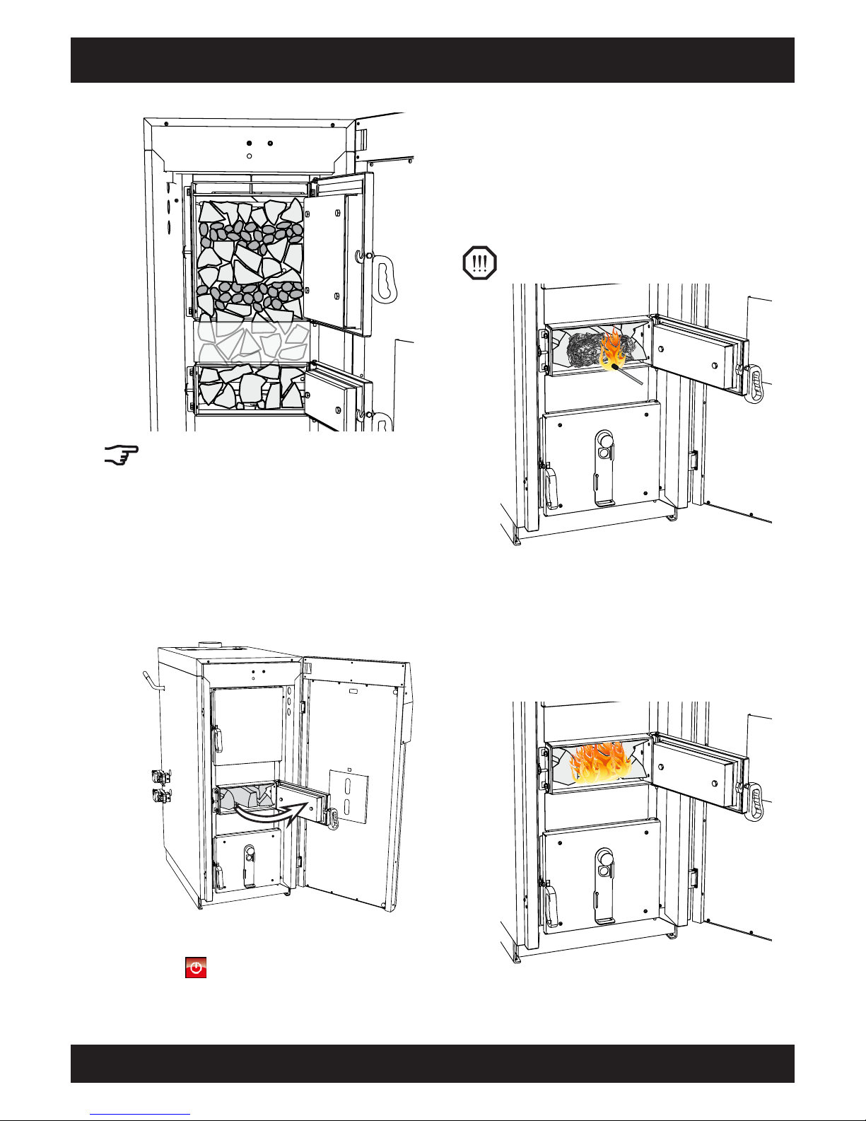
Under no circumstances should brushwood,
coarse wood chips or carpentry waste be used
for the bottom layer. Such fine material burns
too quickly, resulting in incomplete combustion in
the combustion chamber, which is still cold during
start-up. As a result, soot builds up in the heat
exchanger.
Close fuel chamber door, open ignition door
Close the fuel chamber door and then open the
ignition door.
If the boiler is not to be started up yet, close both
doors and in the boiler overview, press the on/off
button so that it shines red.
Ignite the fire with cardboard and newspaper
Place crumpled paper or a few pieces of cardboard
in front of the first layer of wood and ignite it.
The draught fan sucks the flame over the tightly
stacked logs, causing them to ignite more quickly.
For heavy, smooth hardwood, larger pieces of
kindling may be needed for ignition.
Never use petrol, turpentine or similar
materials as an "ignition aid": risk of explosion!
The ignition door should be kept open after
ignition to monitor the progress of the fire. It
should only be closed once the boiler's exhaust gas
temperature has reached 100°C. How long it takes
the fire to start depends on the type of wood used;
rough spruce may need only 2 minutes, smooth
beech may require 5 minutes until the required
exhaust gas temperature of 100°C is reached.
Page 16
16
www.eta.co.at
Closing ignition and insulation doors Star t-up
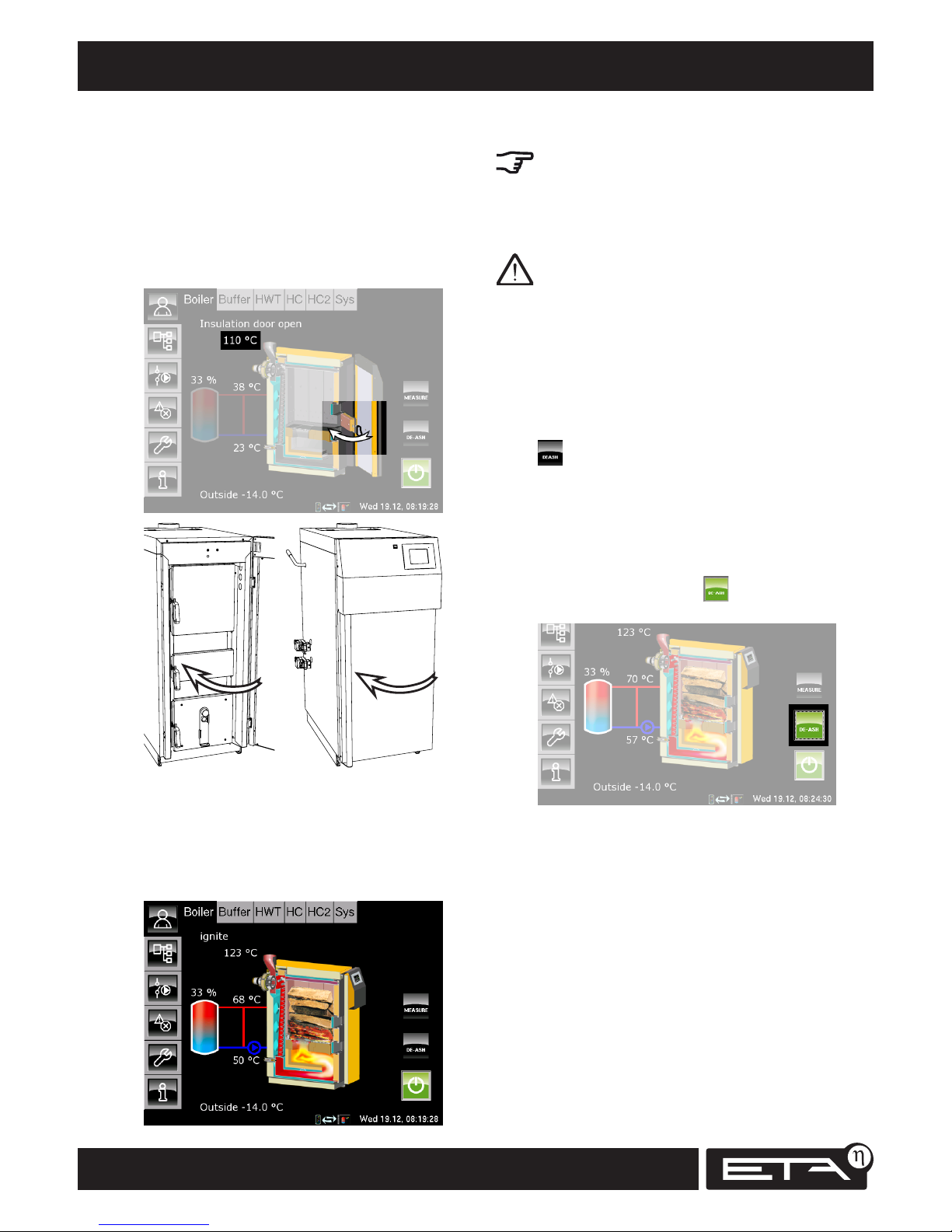
At 100°C exhaust gas temperature, close ignition
door and insulating door.
Once a few logs are burning well and the
exhaust gas temperature is over 100°C, close
the ignition door and the insulating door. The
exhaust gas temperature is displayed in the boiler
overview. At over 100°C, an arrow appears to
indicate that the ignition door should be closed.
When the insulating door is closed, the boiler
automatically switches to ignite mode and,
once the residual oxygen content is below 15%,
to heating mode. The boiler is now in heating
mode and regulates the combustion of the wood
independently.
Avoid opening boiler doors unnecessarily
Avoid opening the insulating door and the fuel
chamber door unnecessarily in heating mode.
That disrupts the boiler control and increases fuel
consumption. Also keep the ignition door and the
combustion chamber door closed.
Never open the insulating door and the fuel
chamber door when the boiler is in "Calibrating
lambda probe" or overtemperature mode.
Completion of heating mode with ember burnout
Once the wood in the boiler has been burned
(residual oxygen content below 15% for more than
5 minutes) or the exhaust gas temperature falls
below 80°C, the boiler automatically starts burnout
("Ember burnout" mode). If the de-ash button
was not pressed, the boiler frees the secondary air ducts of ash with fresh air. Charcoal and
embers remain in the boiler by design so that
newly added wood can be ignited more easily.
Complete ember burnout for cleaning
For cleaning after the last heating operation, in the
overview press the de-ash button (which
then shines green).
Ember retention is then deactivated and the boiler
performs a complete ember burnout (duration
~1 hour), burning most of the charcoal in the fuel
chamber to make subsequent cleaning of the boiler
easier.
Page 17

17
2012-11
Star t-up Adding fuel
SH Operation
Adding fuel
You should only add fuel when the buffer
charging status is below 30% and the fuel
chamber has burned to empty.
If wood has been added and there are still embers
in the boiler, it automatically tries to ignite the
wood again. If the wood is hard to ignite and
there are only a few remaining embers, it may help
to push the charcoal together in the middle before
refilling. If the remaining embers do not ignite the
wood, light it with paper and cardboard through
the ignition door.
Page 18
18
www.eta.co.at
Safety devices to prevent overheating Safety
Safety devices to prevent overheating
The following safety chain takes effect if the boiler
exceeds the operating temperature for any reason:
• over 87°C -> pump safety run
• over 90°C -> draught fan switched off
• over 95°C -> thermal emergency cooling valve
• over 105℃ -> safety temperature limiter
• over 3 bar water pressure -> safety valve
Pump safety run
If the boiler temperature exceeds 87°C (=factory
setting [Pump safety run]), the pump safety run
starts. All heating pumps and boiler pumps
that are connected to the boiler control are
switched on to dissipate heat from the boiler.
This action prevents the boiler temperature from
rising further and triggering further safety devices
such as the safety temperature limiter and thermal
emergency cooling valve. This emergency cooling is
indicated on the display by "heat dissipation".
The heat dissipation is limited with the
maximum flow temperature set in the
heating circuits and the hot water setpoint
temperature.
Boiler overheating
If 90°C boiler temperature (factory setting [Boiler
max.]) is reached, the control system switches
the draught fan off and a warning message
appears on the display. Reasons for a boiler temperature increase include:
• too much wood added (see page 11)
• heating circuits unexpectedly switched off
• heating pump failed
• heating line inadvertently shut off
Once the boiler temperature has fallen below 86°C,
heating resumes automatically.
During such emergency shutdowns the wood
continues to emit gas and the unburned wood
gas causes tar deposits in the boiler and
chimney.
Thermally actuated drain valve (to be supplied by
technician)
Independent of the other safety devices, the
thermal emergency cooling valve is non-electri-
cally triggered at boiler temperatures between
92°C and 97°C. The thermal emergency cooling
valve is opened by means of a sensor system
containing a liquid that expands when heated (no
electricity required). It causes the boiler's safety
heat exchanger to be flooded with drinking
water, dissipating the excess heat out of the boiler
into the sewer.
If the thermal emergency cooling valve activates
frequently, check whether it activates at a
temperature below 92°C and replace it if necessary.
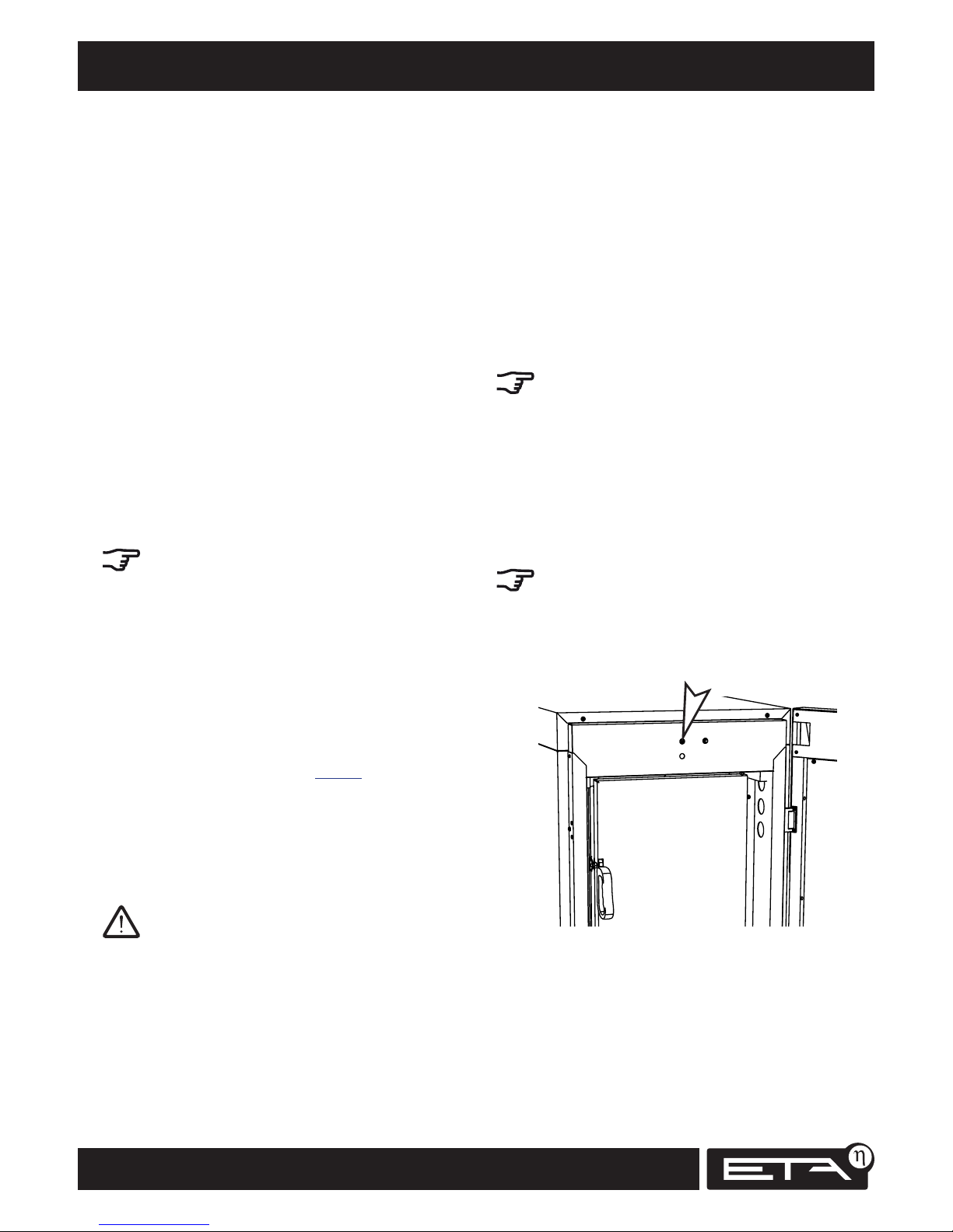
Safety temperature limiter
For additional safety against boiler overheating, a
safety temperature limiter is built into the boiler.
When a boiler temperature of 105°C (tolerance
100°C to 106°C) is reached, the power supply to
the draught fan is switched off.
If the boiler temperature falls below 70°C, the
safety temperature limiter can be manually reset.
The reset button is recessed into the door frame
above the fuel chamber door. To reset, press it
deeply into the recess.
Safety temperature limiter
Safety valve against excess pressure (to be
supplied by technician)
The most common cause of safety valve activation
is either an undersized expansion tank or heating
lines that have been shut off. The safety valve also
serves as a backup safety device to prevent boiler
overheating in the event that all other devices in
the safety chain fail.
Page 19

19
2012-11
Safety Safety devices to prevent overheating
SH Operation
The safety valve must be installed in the flow
line right where it leaves the boiler, as it cannot
dissipate any heat if installed in the return line.
In rare cases when neither the thermal emer-
gency cooling valve nor the safety temperature
limiter trips, the pressure and temperature will
increase until the safety valve opens. If this occurs,
it is crucial to check that the thermal emergency
cooling valve and the safety temperature limiter
are working properly. If cold water is drawn from
an on-premises well with its own pump, a power
failure may be the reason for failure of the thermal
emergency cooling valve. If this occurs frequently,
a larger air chamber in the building's water supply
or a separate air chamber for the thermal emergency cooling valve is required.
Page 20

20
www.eta.co.at
Overview of activities Maintenance
Regular cleaning and servicing
To ensure that the boiler operates optimally and
reliably, it must be cleaned and serviced at regular
intervals.
Maintenance and cleaning of the boiler must be
performed within the specified periods (see table).
Cleaning and maintenance overview
The table provides an overview of the required
cleaning and maintenance.
The "To be done by" column indicates which
activities you as customer can deal with and which
must be performed by an expert.
Activity
Frequency
To be done by
Every 1 - 2
weeks
Annual
maintenance
Every
3 years
Operate cleaning lever X X X Customer
Check water pressure X X X Customer
De-ash boiler X X X Customer
Check walls of ash collection duct X X X Customer
Check safety valves and thermal emergency cooling valve X X X Customer
Clean casing and display X X X Customer
Remove ash behind panels X X Customer
Clean primary and secondary air duct X X Customer
Check and clean flue tube X X Customer
Clean heat exchanger box X X Customer
Check turbulators for tar deposits X X Customer
Clean draught fan X X Customer
Check safety valves X X Customer
Check door seals X X Customer
Check safety devices X Expert
Clean the lambda probe X Expert
Inspect seal on heat exchanger cover X Expert
Perform emission measurement X Expert
Calibrate lambda probe X Expert
Perform heating test X Expert
Reset maintenance counter X Expert
Page 21
21
2012-11
Maintenance Each time the boiler is filled
SH Operation
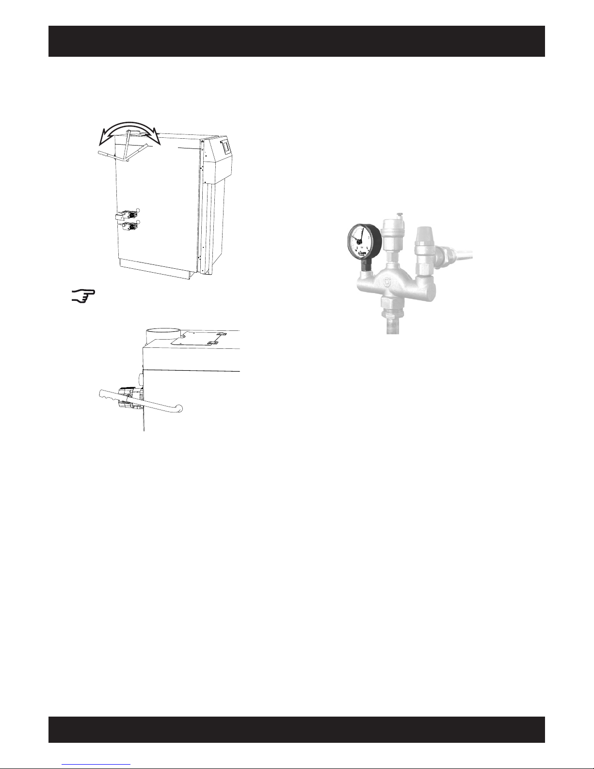
Operate cleaning lever
The heat exchanger's cleaning lever must be
operated 10x before every boiler start-up.
10x
Afterwards, leave the lever pointing towards the
rear of the boiler. Then the turbulators remain in
position in the water-cooled heat exchanger.
Check water pressure
In houses with up to three storeys, the pressure in
a cold system should be between 1 and 2 bar, for
a warm system between 1.5 and 2.5 bar.
If the boiler pressure is too low, fill the cold
heating system to approx. 2.0 bar. This will keep
the pressure below the activation pressure of the
safety valve (3.0 bar) even though it rises when the
water expands with increasing temperature while
heating up to operating temperature.
Page 22
22
www.eta.co.at
Every 1 - 2 weeks Maintenance
Scrape ash and charcoal from fuel chamber into
combustion chamber
The insulating layer of ash in the fuel chamber is
necessary for ember retention, so there should
be approximately 5 cm of ash left in the fuel
chamber. Scrape the remaining ash from the fuel
chamber into the combustion chamber. Some
pieces of charcoal will drop into the combustion
chamber during this process; these are best left
there. The charcoal will burn during the next
combustion cycle and the ash will protect the
bottom of the combustion chamber against
premature wear.
No embers in the rubbish bin
If there are still embers in the ash, leave the ash in
a closed, non-flammable container for at least 2
days. Only put it in the rubbish bin when there are
really no more embers present.
Do not slide the ash collection pan into the boiler
Although the ash collection pan can be pushed
into the ash duct of 40 - 60 kW boilers, it is not
intended for this purpose and would be destroyed
by the high temperatures there.
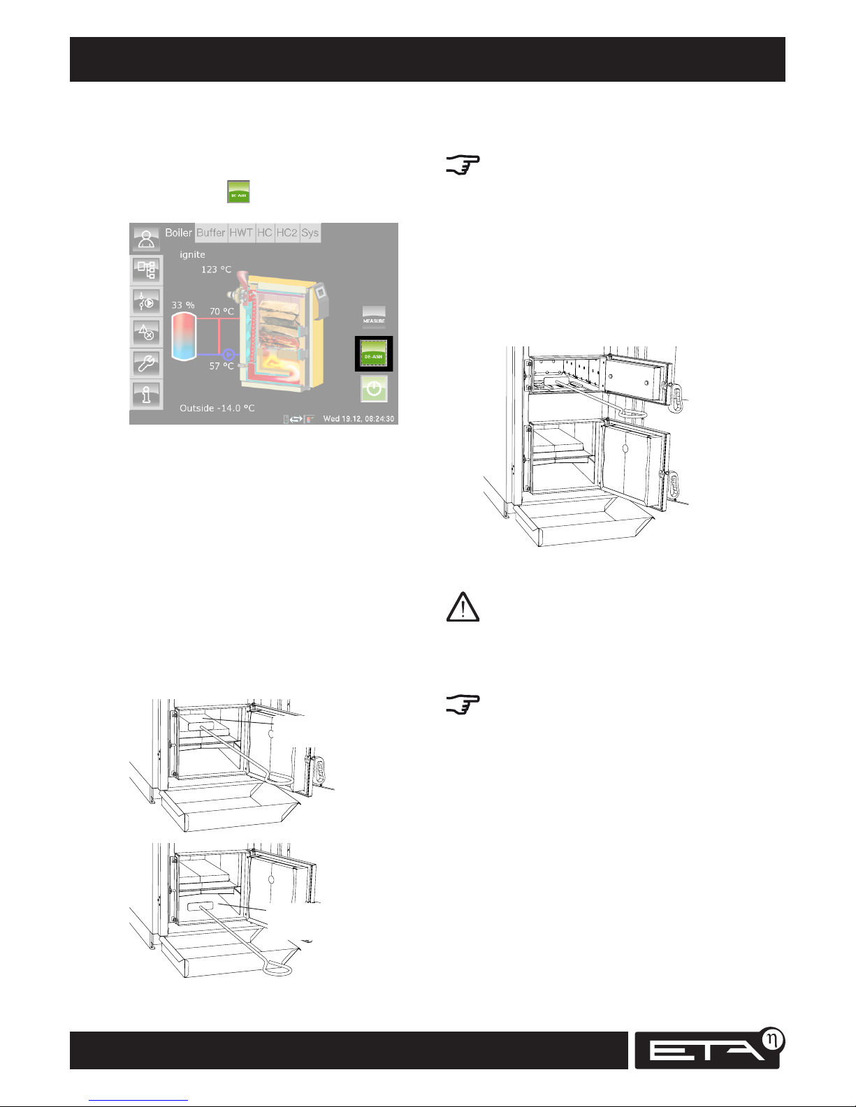
De-ash boiler
Perform complete ember burnout
During final heating operation, in the overview
press the de-ash button (which then shines
green).
Ember retention is then deactivated and the boiler
performs a complete burnout (duration ~1 hour),
burning most of the charcoal in the fuel chamber.
Clean combustion chamber and ash collection
duct
Once the boiler has cooled off, rake the ash out of
the fire box and the ash collection duct into the
ash collection pan. The rear end of the ash collection duct must also be cleared out so that there is
no ash in front of the lambda probe head. If the
draught fan is running while you are removing the
ash, remove it from the boiler slowly and gently to
avoid stirring it up too much and having it blown
out through the flue.
Combustion
chamber
Ash collection
duct
Page 23
23
2012-11
Maintenance Every 1 - 2 weeks
SH Operation
Check walls of ash collection duct
The walls of the ash collection duct may be white
to brown in appearance. If they are black with
soot, either too much wood was burned at too low
a heat consumption (page 11), the fire was not
lit correctly at start-up or, in very infrequent cases,
the lambda measurement gave incorrect values.
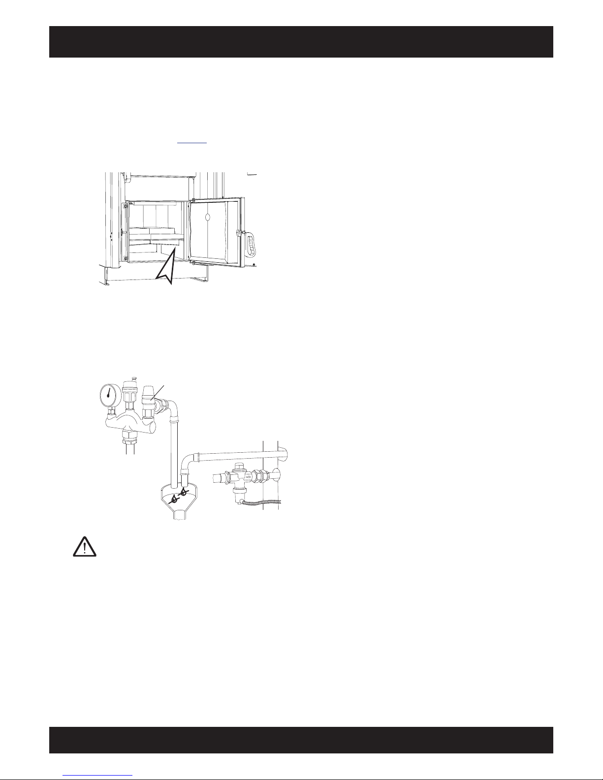
Check safety valves and thermal
emergency cooling valve
The safety valve and the thermal emergency
cooling valve may not drip. Dirt may be stuck in
the seal seat.
Safety valve
Thermal emergency
cooling valve
Only perform further steps on weekdays, never
check on weekends in a cold winter as there will
probably be no heating technician available if the
seal is defective. If the valve drips, open the safety
valve with a quarter turn of the red cap and rinse
it out (danger of scalding). If the valve still cannot
be closed tightly after being rinsed several times, it
must be cleaned by a plumber or replaced.
If a solar heating system is to be connected to the
buffer storage tank, the safety valve installed there
must also be inspected.
Clean casing and display
Clean the boiler casing with a damp cloth and
(if necessary) a commonly available household
cleaner (no scouring agents). Clean the display
only with a damp cloth (no cleansing or scouring
agents).
Page 24
24
www.eta.co.at
Annually Maintenance
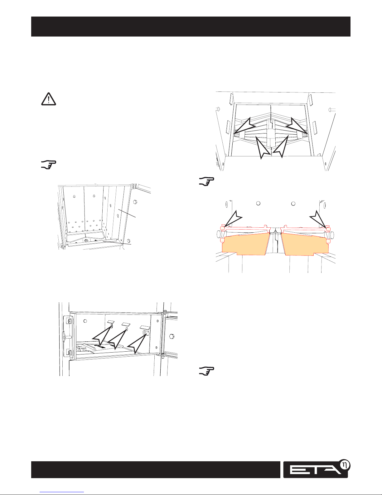
Clean secondary air openings
Remove both parts of the grate and remove the
ash beneath them. Then remove the ash from
both secondary air openings at the sides.
When inserting the grate, take care that the seal
(above the secondary air opening) is in the semi-
circular groove on the grate.
Check and clean flue tube
Check that the flue tube from the boiler to the
chimney is air-tight. The points at which dust or
flue gas escape can be identified by discolouration.
The exhaust gas pipe can be sealed with heatresistant silicone (400°C) and aluminium sealing
tape. Since there are many different alternatives for
connecting the exhaust gas pipe to the chimney,
it is best to consult the chimney sweep regarding
leaks in the connection.
Flue pipes with a horizontal run longer than 1
metre must be brushed out.
Annual maintenance
In preparation, perform weekly maintenance
Before annual maintenance, all steps of the weekly
maintenance must be performed.
Before starting work, let the boiler cool off
and switch it off with the mains switch.
Remove ash behind panels
The panels are hung from a bolt at the top. Lift the
panels slightly, pivot them out and remove them
from the fuel chamber. Remove the ash behind
them.
After removing the front panels, remove the guard
plate between the fuel chamber and ignition doors
so it cannot fall down.
Panels
Guard plate
Clean primary air openings
The openings for primary air are behind the
panels around 10 cm above the floor of the fuel
chamber. Clean these openings with a vacuum
cleaner.
Page 25
25
2012-11
Maintenance Annually
SH Operation
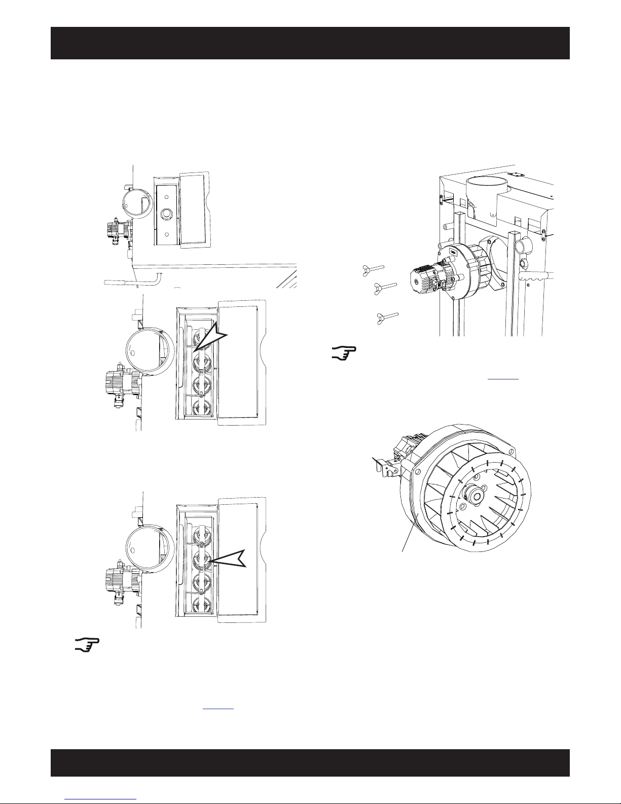
Clean heat exchanger box
Open the heat exchanger cover (at the top of the
boiler in front of the exhaust gas pipe) and remove
the ash from the heat exchanger box with a
vacuum cleaner. Do not close the chamber again
until the draught fan has also been cleaned.
Check turbulators for tar deposits
Check the turbulators in the heat exchanger for
tar deposits.
The turbulators must be removed as soon as
the cleaning lever becomes difficult to move.
If the turbulators and their supporting brackets
have tar deposits, the cause is often the addition
of more wood than is needed to meet the actual
heating requirements (see page 11).
Clean draught fan
Disconnect the power supply, remove the 3 wing
screws and pull out the fan. Clean the fan wheel
with a soft brush, toothbrush (no wire brush) or
compressed air so that the motor shaft does not get
bent.
If there are tar deposits on the draught fan's
wheel, that is a sign that too much wood is
always being added (see table on page 11), or
the lambda probe is defective and providing false
measurements.
Check seal
Before installing the draught fan, check the
seal. Make sure that the plug connection on the
installed draught fan is pointing to the right (as
seen from the back of the boiler).
Page 26
26
www.eta.co.at
Annually Maintenance
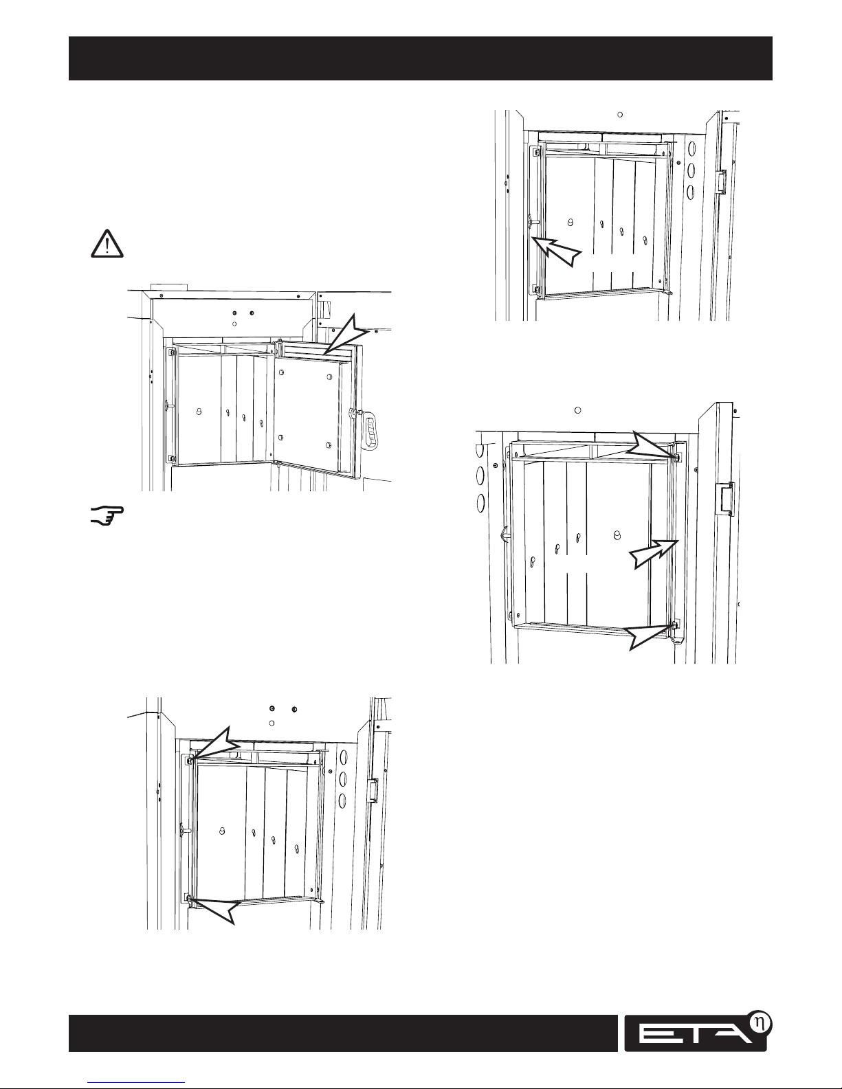
Check door seals
Check the seals on the 3 boiler doors (fuel
chamber door, ignition door, combustion chamber
door). The door handles must close firmly (with
force), and the sealing edges of the door frames
must leave a clear impression on the sealing cord.
In particular, check the seal between the carbo-
nisation gas extraction duct and the fuel chamber
door.
Leaks can be identified by variations in the
colouring on the seal or by using a cigarette lighter
while the draught fan is running. The flame will
be drawn toward the leak. If leaks are found, it is
usually sufficient to adjust the hinges and the
closing roller mount. It is not always necessary to
replace the sealing cords.
To adjust, open the door and lift it from its hinges.
Loosen the two hexagonal nuts next to the closing
roller mount and move the mount by 0.5 - 1 mm
towards the rear of the boiler.
0.5 - 1 mm
The boiler door hinges are adjusted in the same
manner. Loosen the two hexagonal nuts next to
the hinges and move the mount by 0.5 - 1 mm
towards the rear of the boiler.
0.5 - 1 mm
Then tighten the hexagonal nuts, reattach the
boiler door and check that it closes tightly.
Page 27

27
2012-11
Maintenance Annually
SH Operation
Page 28
28
www.eta.co.at
Every 3 years Maintenance
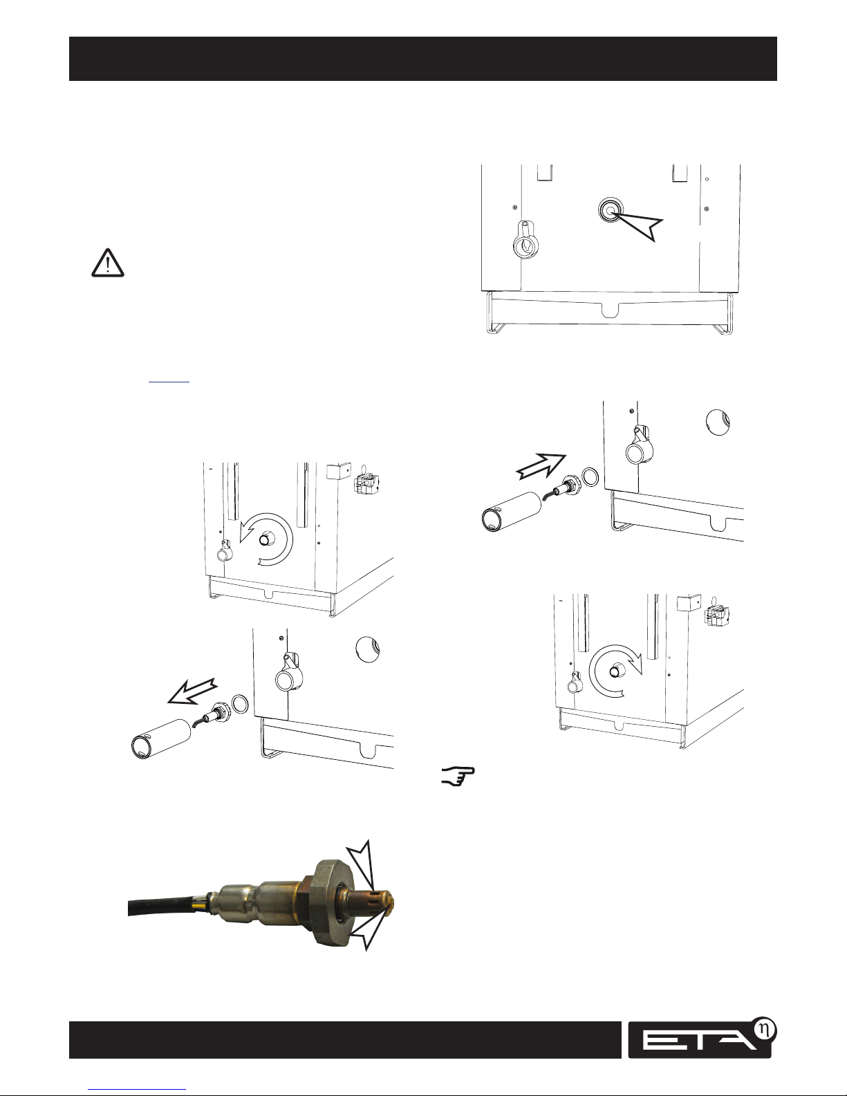
Clean the lambda probe's seal seat in the boiler.
It must be absolutely clean. Inspect it with a torch
and clean out the coupling with a vacuum cleaner.
Clean
The copper washer for sealing the lambda probe's
metal flange and the seat in the boiler must be
replaced when installing the probe.
Tighten the lambda probe securely (with 20 kg and
20 cm lever arm).
Excessive wear on the combustion chamber is often
due to leaky installation of the lambda probe. Leak
air penetrates the boiler and the control system
reduces the air intake too much and the temperatures in the combustion chamber reach forbidden
levels.
Inspect seals on heat exchanger cover
Check the heat exchanger cover's seals and
replace as needed.
Maintenance by expert, every 3 years
or after alert by control system
In preparation, perform weekly and annual
maintenance
Before this maintenance, all steps of the weekly
and annual maintenance must be performed.
Before starting work, let the boiler cool off
and switch it off with the mains switch.
Check safety devices
Check safety valves, thermal emergency cooling
valve and safety temperature limiter
See page 23.
Clean the lambda probe
Use a pipe wrench to unscrew the lambda probe's
retaining tube.
Let the lambda probe cool off and clean it with
a vacuum cleaner. Take special care to clean the
openings in the head of the lambda probe.
Page 29
29
2012-11
Maintenance Every 3 years
SH Operation
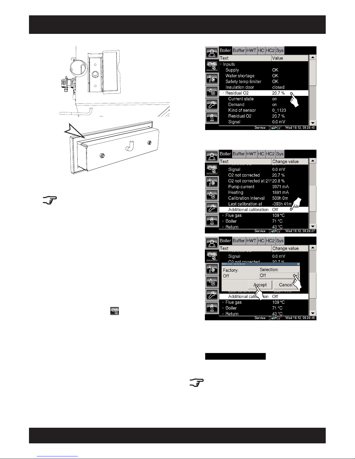
In the submenu, scroll down and double-tap the
[Additional calibration] line.
2x
In the selection window that appears, select
[On] button and confirm with [Accept]. The
control system will now automatically calibrate the lambda probe. The boiler is now in
Calibrating lambda probe
mode. When calibration is complete, the boiler returns to "Ready"
status.
After 100 hours at full load, the control system will
automatically perform a re-calibration.
Calibrate lambda probe
After every 500 hours of full-load operation,
the boiler performs an automatic calibration of
the lambda probe. This always occurs after an
ember burnout and only at night between 23:00
and 04:00. This calibration can also be initiated
manually by opening the primary and secondary
air valves and flushing the boiler with fresh air
using the draught fan.
If the boiler has not been in use for over 48 hours,
this calibration takes only 30 minutes. If the boiler
was in operation until recently, the calibration
can take up to 3 hours. If the boiler is started up
during calibration, the calibration is aborted and
started again 9 days later.
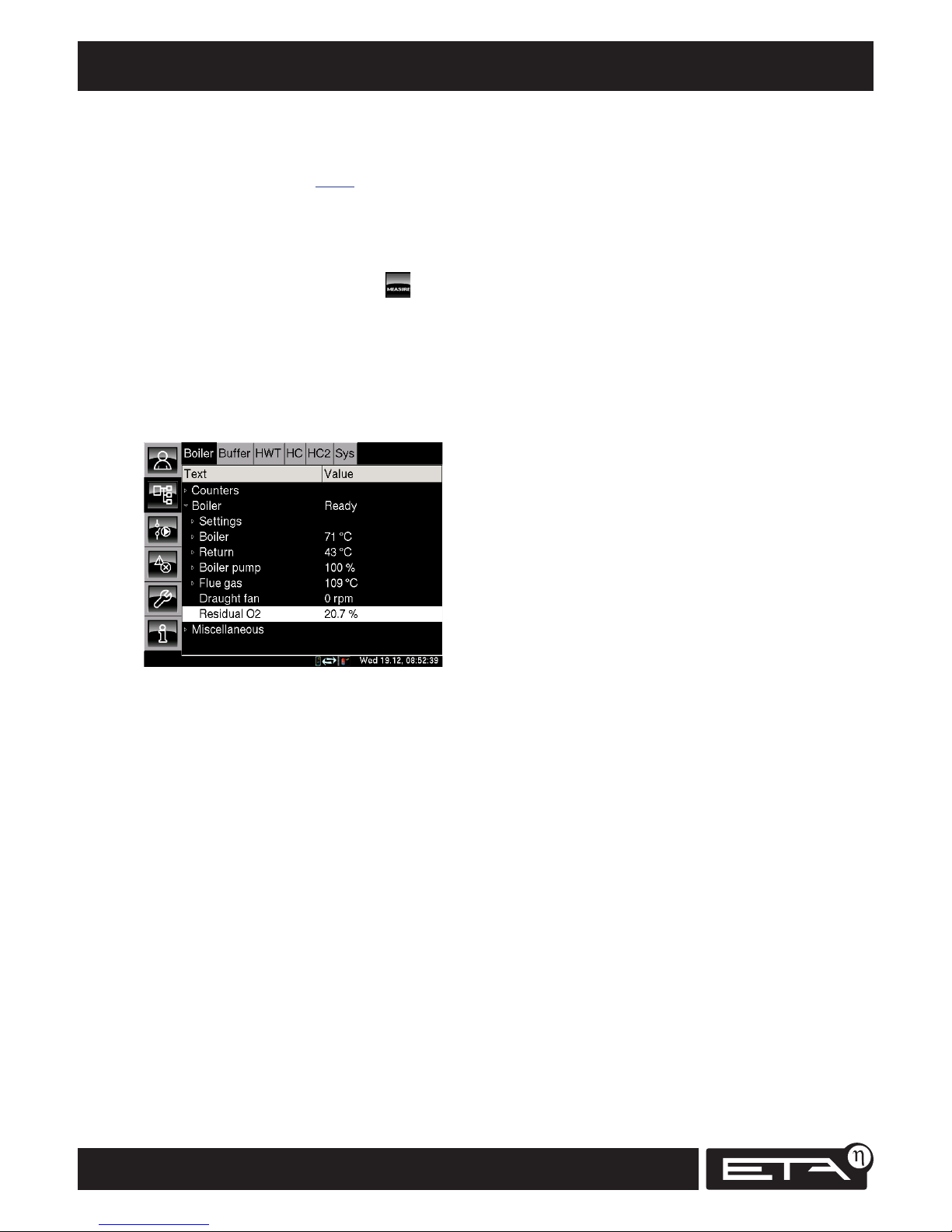
Using the Service access level, open the text menu
by pressing [Boiler] and . Tap the [Inputs] line.
In the submenu, tap the [Residual O2] line.
Page 30
30
www.eta.co.at
Every 3 years Maintenance
Perform emission measurement
Perform the emission measurement with a measuring device on the boiler; see page 6.
Perform heating test
Place logs in the fuel chamber, ignite them and
wait 15 minutes. Then switch the boiler to
emission measurement mode by pressing .
The control system ensures that sufficient heat is
channelled to the buffer, the heating circuits and
the hot water tank.
After around 10 minutes, a residual oxygen value
of 4.5 to 7% should be reached. The current
residual oxygen content is displayed in the boiler's
text menu under [Boiler] at [Residual O2].
If the value does not drop below 12% residual
oxygen, the boiler is receiving leak air. The
reason (leaky boiler doors, heat exchanger cover,
lambda probe installation etc.) must be identified
and corrected.
Reset maintenance counter
After expert maintenance, the maintenance
counter must be reset to zero. "Service" level access
is required to do this.
Page 31

31
2012-11
SH Operation
Page 32
32
www.eta.co.at
Approval, antifreeze, pressure equalisation, venting
Approval
Every heating system must be approved.
Inquire at you building authority and ask your
chimney sweep.
Operation only by trained personnel
The system may be operated only by trained
personnel. Instruction can be given by the heating
installer or our customer service. Please read this
user manual to be assured of avoiding errors in
operation and maintenance of the boiler.
Fire extinguisher
In Austria at least a powder extinguisher ABC 6 kg is
required. Better is a foam extinguisher AB 9 litre,
which causes less damage when extinguishing.
The fire extinguisher should be kept outside the
boiler room, easily visible and easily accessible.
In Germany and Switzerland, no fire extinguishers
are required for heating systems in private
residences. In spite of this, we recommend having
one in the house.
Children must be kept away from the boiler
room and pellet store.
Antifreeze
If a house with average insulation is unoccupied
in winter at low temperatures for more than five
days, check once a week (twice a week for very
low temperatures) to make certain that the boiler is
operating properly.
If the building is unoccupied in winter for longer
intervals, up to 30% antifreeze can be added
to the heating water. To compensate for the
disadvantage of reduced heat capacity and
increased flow resistance, only slightly higher flow
temperatures are needed.
Insulate contact sensors
If the pipe in the vicinity of a contact temperature
sensor is not insulated (e.g. in externally installed
heating circuit groups), lower than actual
temperatures will be measured. For this reason,
pipe insulation may not be recessed or weakened
for heating circuit flow sensors. For uninsulated
piping systems, the measurement area must be
insulated with mineral wool at least 20 mm thick
over a length of at least 20 cm of pipe.
Pressure equalisation
For pressure equalisation in the system, a
diaphragm expansion tank with a gross capacity of
around 10% of the system volume is needed (see
conditions for guarantee and warranty).
All shut-off valves along the path from the
expansion tank to the boiler and to the buffer
storage tank must be capped valves, or the hand
wheels or levers must be removed from the valves
(hang on the valve with a wire) to ensure that they
cannot be closed by accident.
If the pressure difference between cold and warm
heating system (buffer fully loaded if installed)
is greater than 1.0 bar for a single-floor system
or 0.5 bar for a three-storey system, then the
expansion tank is too small and absolutely must
be replaced with a larger one. If the installed
expansion tank is not large enough, the system
sucks in air when cooling and the air is absorbed
by the cold water and transported to the boiler.
At the point of highest temperature, the air
separates from the water again. This is the usual
situation in the boiler, and the inevitable result
is that the boiler wall will rust through at these
places.
Venting
Automatic venting valves in the boiler outlet, at
the highest point in the distribution network and
at the top of the buffer significantly reduce the
danger of rust and also the frequency of radiator
venting.
Page 33

33
2012-11
Softened water, safety valve
SH Operation
Initial fill-up with softened water and
enough shut-off valves
All relevant standards demand softened water for
heating systems with larger water volumes.
For the boiler a value of 20,000 lt°dH for system
volume in litres multiplied by the hardness
(in degrees of German hardness) may not be
exceeded.
A system volume of 300 litres (boiler and heating
elements) and very hard water with 30°dH yields
a value of 9,000 lt°dH. In this case, the system can
still be filled with unsoftened water.
For a heating system with a 1000-litre buffer, for
example, the total volume is 1300 litres. Even with
water that is not very hard, such as 20°dH, a value
of 26,000 lt°dH results; that is too high. For a
volume of 1300 litres, the water must be softened
to less than 15°dH (20,000 divided by 1,300).
Around 0.25 kg of limescale will precipitate from
a cubic metre of water with 15°dH, resulting in
a limescale layer 0.2 mm thick on a quarter of
a square metre of the boiler's heat exchanger
surface; this small area in the boiler is where the
lime build-up is concentrated. This may not seem
serious, but with 2 m³ of buffer storage and a
system volume of 0.5 m³, a thickness of 0.5 mm
is reached. Thicker layers hinder the heat flow
through the boiler wall to the extent that it is no
longer cooled sufficiently and heat stress cracks can
form.
In practice, that means the boiler can tolerate a
buffer filled with unsoftened water as long as
no repairs and no leaks in the system (defective
air valves or safety valves that fail to close) force
water to be refilled during the further course of the
system's service life.
To have a sufficient safety reserve for additions,
the new system must be filled with softened
water, meaning that the empty system must really
be filled exclusively with softened water before
starting the boiler for the first time. Changing
the water after the boiler has already been in
operation is too late since the limescale from the
unsoftened water has already precipitated in the
boiler.
To reduce the amount of water replacement for
later repairs, it must be possible to shut off all large
volumes such as buffers, boiler and heating circuits
to keep the lime content to a minimum during
water additions.
Protection against corrosion
To limit corrosion with softened water, the
pH value should be adjusted to between 8 and 9
using suitable inhibitors (trisodium phosphate).
Safety valve against overpressure
Install a safety valve with 3 bar opening pressure
on the boiler (is already installed for PU and
PC boilers). No shut-off valve may be installed
between the boiler and the safety valve. If solar
or other heat sources provide energy to the buffer
storage tank via a heat exchanger, a safety valve
(3 bar maximum) is also required on the buffer
storage tank. Normally an expansion tank that is
too small or defective, or blocked heating lines, are
the cause for activation of the safety valve.
The safety valve must be on top of the boiler in
the flow in order to also discharge heat in an
emergency. Only this way can it discharge heat
when it blows out hot water and also steam.
The discharge must be directed to the sewer via
an easily visible, open flow path (siphon funnel)
so malfunctions and, above all, a non-closing
valve can be recognised. If no sewer is available,
the discharge must be directed into the ground in
a pipe so nobody is endangered by hot water or
steam.
Page 34
34
www.eta.co.at
Return riser and safety devices
Return riser
Wood contains water. If the temperature in the
boiler is too low, steam condenses from the flue
gas onto the heat exchanger surfaces. Corrosion
and a leaky heat exchanger are the result. To
prevent this, the water temperature at the boiler
inlet must be at least 60°C. Since the return
temperatures are usually lower, a return riser is
needed - preferably with a mixer that provides
controlled, heated flow to the boiler return.
The return riser mixing valve controls the buffer
charging output. To reduce the output, the return
temperature is raised over 60°C to reduce the
spread compared to the boiler's setpoint temperature. With the spread the output that can be
consumed from the boiler is limited.
Thermal emergency cooling valve against
overheating
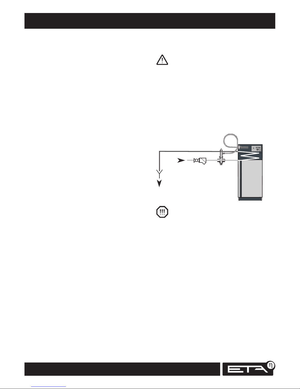
The safety heat exchanger built into the boiler
must be connected by the heating technician to
the house's cold water supply via a thermal outlet
valve (opening temperature 95 °C) to protect the
boiler against overheating if the pump fails. The
minimum pressure in the cold water line must be
2 bar.
Connect the supply line to the lower connector of
the safety heat exchanger; the upper connector is
for outlet to the sewer. To prevent the supply line
from being shut off accidently, remove the levers
from shut-off valves or the hand wheels from
valves and hang them there with a piece of wire.
Thermal
emergency
cooling valve
Strainer
visible drain to
sewer
Cold water
connection
Isolating valve
Remove hand wheel
The discharge must be have an easily visible, open
flow path so malfunctions can be recognised.
Direct the discharged water to the sewer via a
siphon funnel or at least with a pipe into the
ground so that nobody can be scalded if the valve
is activated.
Even for cold water coming from a domestic well
with its own pump, a thermal emergency cooling
valve must be installed on the boiler. With a
generously dimensioned air vessel, enough water
for cooling will come even if there is a power
failure. If the electricity supply is very uncertain,
a dedicated air vessel for the thermal emergency
cooling valve is required.
Page 35
35
2012-11
Minimum heat consumption, buffer storage tank
SH Operation
A minimum power level is necessary to achieve
clean and complete combustion
The smaller the fire in the boiler, the lower the
temperature will be in the combustion chamber.
At about a third to a quarter of the full load, the
combustion temperature drops below 700°C and
the tar components in the wood gas no longer
burn completely. This drastically reduces the
efficiency (it can drop to below 50%), causes tar
build-up in the boiler's heat exchanger and in the
chimney and also results in unacceptable pollution
due to unburned hydrocarbons.
To maintain a clean-burning wood fire with
maximum fuel efficiency, a minimum power level
must be maintained and the best way to achieve
this is to use a buffer storage tank.
Why a buffer storage tank?
Many old log boilers that do not have buffer
storage tanks are still in use, so why do we need
them with today's wood-burning systems? The
answer to this frequently asked question is as
follows: In the days before heating control systems,
the boiler used the thermal mass of the entire
house as a buffer. If the boiler is replaced, and the
radiators are fitted with new thermostat valves
and/or a weather-dependent mixing system, the
log boiler is forced to operate at too low an output
level in autumn and spring when the heating
requirements are minimal. At low output levels,
the temperature in the combustion chamber drops,
but production of wood gas doesn't. Hard-to-burn
components of the wood gas, such as tar or acetic
acid no longer combust; instead, they condense
(create tar deposits) either in the boiler's heat
exchanger or in the flue. The materials that are not
deposited pollute the environment.
A buffer storage tank is necessary to control this
low-load operation, which inevitably occurs with
a modern, energy-saving heating system. Heat
produced by the boiler for which there is no immediate use within the building is offloaded into a
buffer storage tank and retrieved by the heating
system as needed, for example, when the boiler is
not operating.
As a log wood boiler cannot simply be switched off
once it has been started up and while there is still
wood burning in it, it must be possible to store in
the buffer the energy content of the wood that is
still in the combustion chamber.
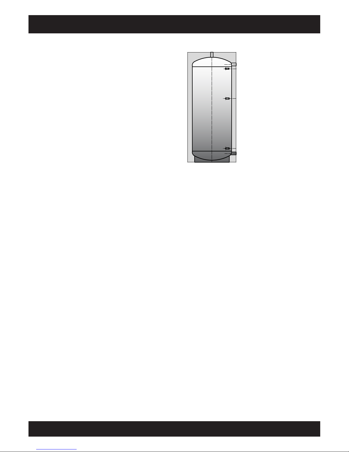
Flow from boiler
to hot water tank
"Buffer bottom" temperature
sensor just above connection
Return to boiler
The boiler controls its output based
on the reading from the "Buffer
middle" temperature sensor.
Enough to provide sufficient heat
to start a consumer. Not too much
to ensure that the buffer is still
able to store heat after the heating
circuits have been switched off.
"Buffer top" temperature sensor
just under the connection
No external timer thermostats
The factory-standard controls include weekly
timers for two heating circuits.
If the heating pumps are controlled by the boiler
control, heat can be drawn from the boiler during
periods when the temperature setting has been
lowered as long as there is wood in the boiler.
This is especially important if you accidentally
put too much wood on in the evening, or if you
intentionally heat up the boiler to its full extent in
anticipation of a cold night.
Timer thermostats will switch off the heating
pumps punctually at the preset time, even if
wood is still burning in the boiler, and even if the
(undersized) buffer is incapable of storing more
heat. The only solution for the boiler is to stop its
air intake. Although this puts the fire out without
the boiler overheating, the wood will continue to
emit gas and the unburned wood gas resulting
from the lack of air will create tar deposits in the
boiler and flue.
Page 36
36
www.eta.co.at
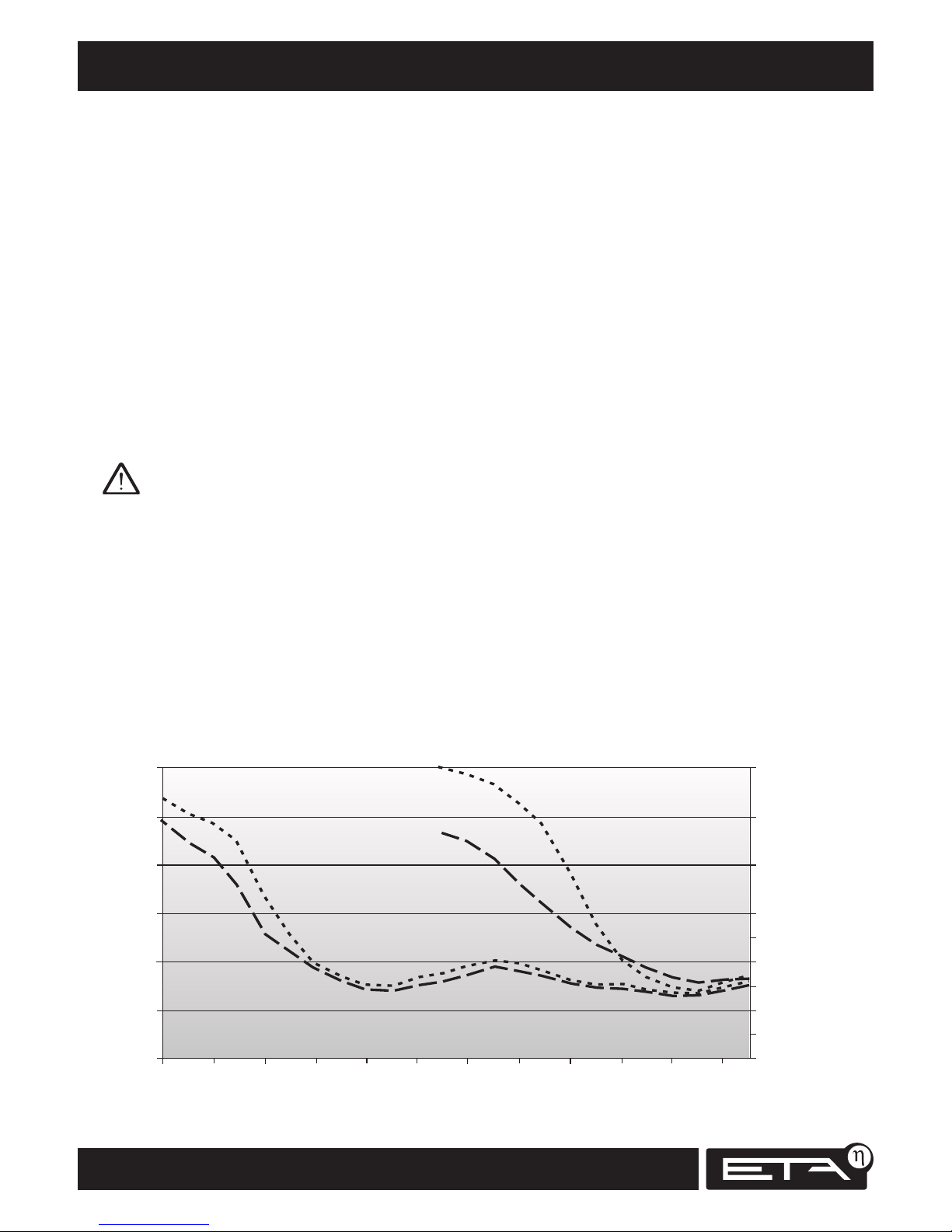
Split wood will dry out in just one summer
Why use dry split logs?
The moisture content of split logs intended for a
log boiler should be below 20% (air dry).
Damp wood with a moisture content of above 20%
creates a moist climate in the fuel chamber. Wood
that is not sufficiently dry can cause the boiler's
fuel chamber to rust through.
One summer is sufficient to dry out split firewood
Unsplit logs stacked as metre-long pieces in the
forest will generally take two summers to dry.
However, it can be done faster. If the timber is
felled in winter (before the end of January) and
split immediately, a moisture content of 15% can
be reached by September through air drying. Split
logs also burn far better than unsplit logs.
Unsplit logs take two months longer, and thus a
second summer, to dry.
The best approach is to split the wood in lengths
of 1 m immediately after felling: split in half for
a log diameter of up to 15 cm; into quarters for a
diameter up to 20 cm, into sixths for a diameter up
to 25 cm, and into eighths for a diameter up to 30
cm.
Store the split wood in a windy place on a dry
surface; ideally stack crosswise on two logs or
concrete pipes and cover only the top. Of course
a sunny location is preferable, but it is more
important to find a dry, windy place. Leave a gap
between stacks as well. If you stack wood along
the wall of a house, leave an air gap of at least 10
cm between the wall and the stack of wood.
Wood stored outside in winter will absorb moisture
from precipitation. For this reason either move the
wood to a covered location in September or, as a
minimum, temporarily store it in a warm room for
a week before burning.
During storage the heating value is reduced by
processes similar to decay; depending on how dry
storage conditions are, the loss can be between
1% and 3% per year. For this reason, only store
firewood for longer than 3 years in exceptional
circumstances.
Split the wood and store it in a dry, windy place,
one percent moisture more or less will not make
a big difference
To sum up: the heating value changes by only 2%
between 20% and 10% moisture content. It is
easy to achieve less than 20%—even if you cut the
wood in summer—if you split the wood and store
it outdoors with protection against the rain for a
year.
Fichte
Fichte
Buche
Buche
60
30
40
50
20
0
10
%
Wassergehalt
F
e
b
0
3
O
k
t
0
3
A
u
g
0
3
J
u
n
0
3
A
p
r
0
3
D
e
z
0
2
D
e
z
0
3
F
eb
0
4
O
k
t
0
4
A
ug
0
4
J
u
n
0
4
A
p
r
0
4
Quelle: “Rationelle Scheitholzbereitstellungsverfahren” Bericht 11 TFZ Straubing, von ETA mit Heizwertangabe ergänzt
82,4
89,0
93,5
96,6
97,7
99,0
100,0
102,4
101,7
100,9
%
Heizwert bezogen auf 15% Wassergehalt
Page 37
37
2012-11
Heating value of wood
SH Operation
Heating value of wood
Split wood is typically sold in stacks by the cubic
meter. The energy content depends not only on the
type of wood. The amount of heat a cubic metre
contains also depends on whether the wood is
unsplit round logs, metre-long split logs, or readyto-burn split logs, and on whether it is fresh from
the forest or dried for firewood.
The wood volume stays constant from when it is
freshly cut with a moisture content of 60% to the
fibre saturation point at 25%. The wood starts
to contract if dried below this point. It reduces
in size, and this is why air-dried wood (moisture
content of 15%) has more wood substance than
freshly cut wood per cubic metre. The difference is
typically 5% to 6% for softwood, and 6% to 9%
for hardwood.
Logs are not straight. The longer the logs are, the
less wood and the more air is present per cubic
metre. There is typically more air in "crooked"
hardwood than in "straight" softwood.
There is one further difference: round logs can
typically be stacked in a far more compact way
than metre-long split logs. If you split the wood
yourself, buying round logs will give you up to
15% more wood per cubic metre.
In practice, deviations on the order of +/-10%
compared with theoretical values are to be
expected. Up to 20% is possible in extreme cases:
not only if the wood is particularly straight or
crooked, but also because the density of the wood
mass itself can vary.
Incidentally, if you order a cubic metre of ready-toburn beech firewood as 50 cm split logs from your
wood dealer, the dealer is entitled under current
law to supply 0.85 m³ of half-metre split logs cut
from 1 m³ of 1 metre long split logs. To avoid any
unpleasant surprises, when ordering ask how your
dealer measures a cubic metre (if the price is good,
you may find 0.85 m³ acceptable).
Estimating your wood requirements
Each kilowatt of heat output requires 0.9 cubic
metres of half-metre split beech logs, or 1.3 m³ of
split spruce per year.
In other words, 8 m³ of half-metre split spruce
logs or 5.5 m³ of beech will replace 1000 litres of
heating oil.
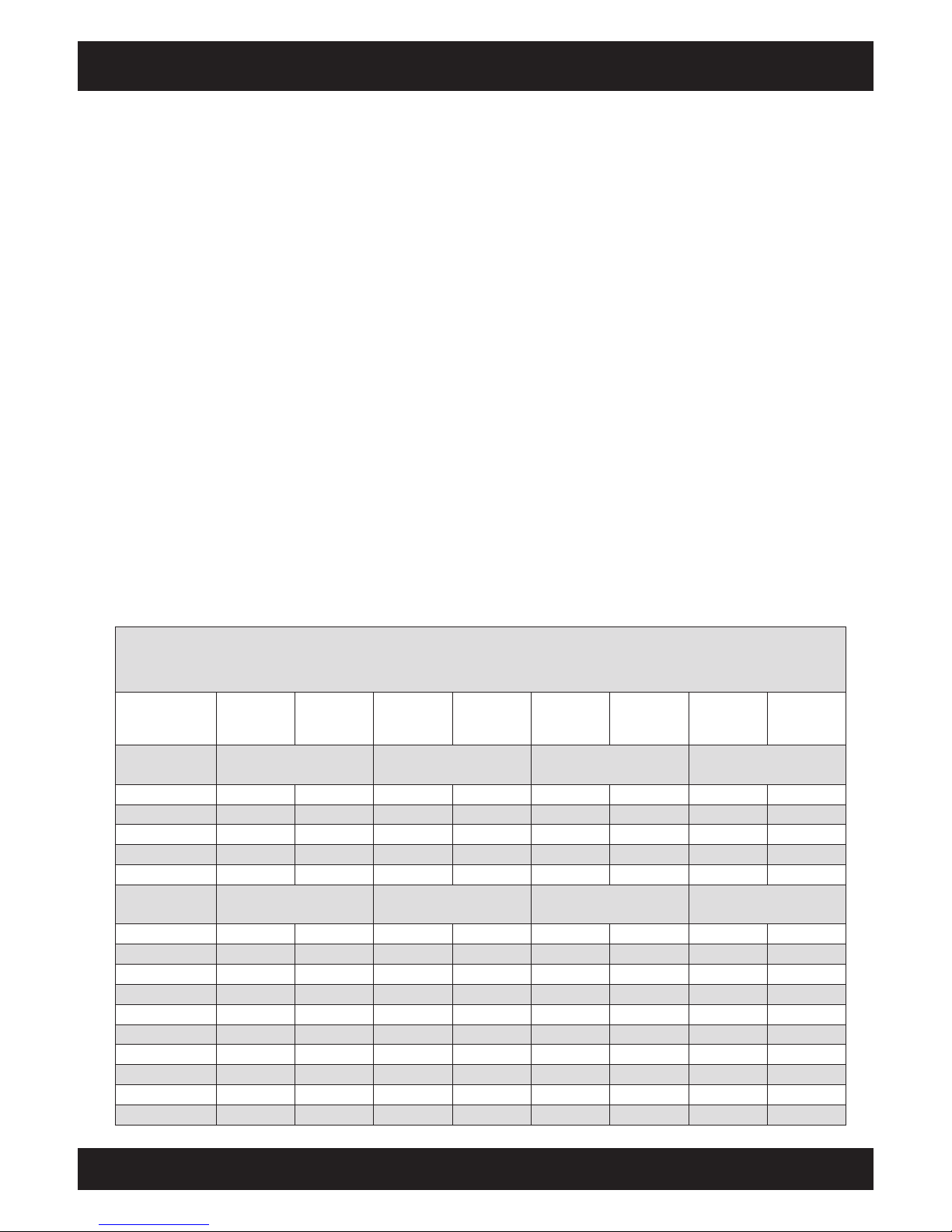
Energy content of one cubic metre of wood in kilowatt hours
The table assumes that the firewood used is split and air-dry (after one year's storage) with a moisture content of around
15% when burned even if it was moist when bought.
Round logs 1 m
freshly cut
w=30-60%
Round logs 1 m
dry w=15%
Logs 1 m
freshly cut
w=30-60%
Logs 1 m
dry w=15%
Logs 50 cm
freshly cut
w=30-60%
Logs
50 cm
dry w=15%
Logs 33 cm
freshly cut
w=30-60%
Logs 33 cm
dry w=15%
Softwood
1 stere contains 0.65 m³1 stere contains 0.56 m³1 stere contains 0.62 m³1 stere contains 0.64
m³
Fir
1,205 1,269 1,038 1,093 1,149
1,210
1,186 1,249
Spruce
1,299 1,373 1,119 1,183 1,239 1,310 1,279 1,352
Douglas fir
1,402 1,478 1,208 1,274 1,337
1,410
1,380 1,455
Pine
1,542 1,625 1,329 1,400 1,471
1,550
1,519 1,600
Larch
1,573 1,656 1,355 1,427 1,501
1,580
1,549 1,631
Hardwood
1 stere contains 0.59 m³1 stere contains 0.50 m³1 stere contains 0.59 m³1 stere contains 0.62
m³
Poplar
958 1,020 812 864 958
1,020
1,007 1,072
Willow
1,107 1,200 938 1,017 1,107
1,200
1,163 1,261
Alder
1,191 1,270 1,009 1,076 1,191
1,270
1,252 1,335
Maple
1,472 1,550 1,247 1,314 1,472
1,550
1,547 1,629
Birch
1,475 1,570 1,250 1,331 1,475
1,570
1,550 1,650
Ash
1,658 1,760 1,405 1,492 1,658
1,760
1,742 1,849
Oak
1,664 1,760 1,410 1,492 1,664
1,760
1,749 1,849
Beech
1,655 1,800 1,403 1,525 1,655 1,800 1,739 1,892
Hornbeam
1,743 1,920 1,477 1,627 1,743
1,920
1,832 2,018
Black locust
1,743 1,920 1,477 1,627 1,743
1,920
1,832 2,018
Page 38
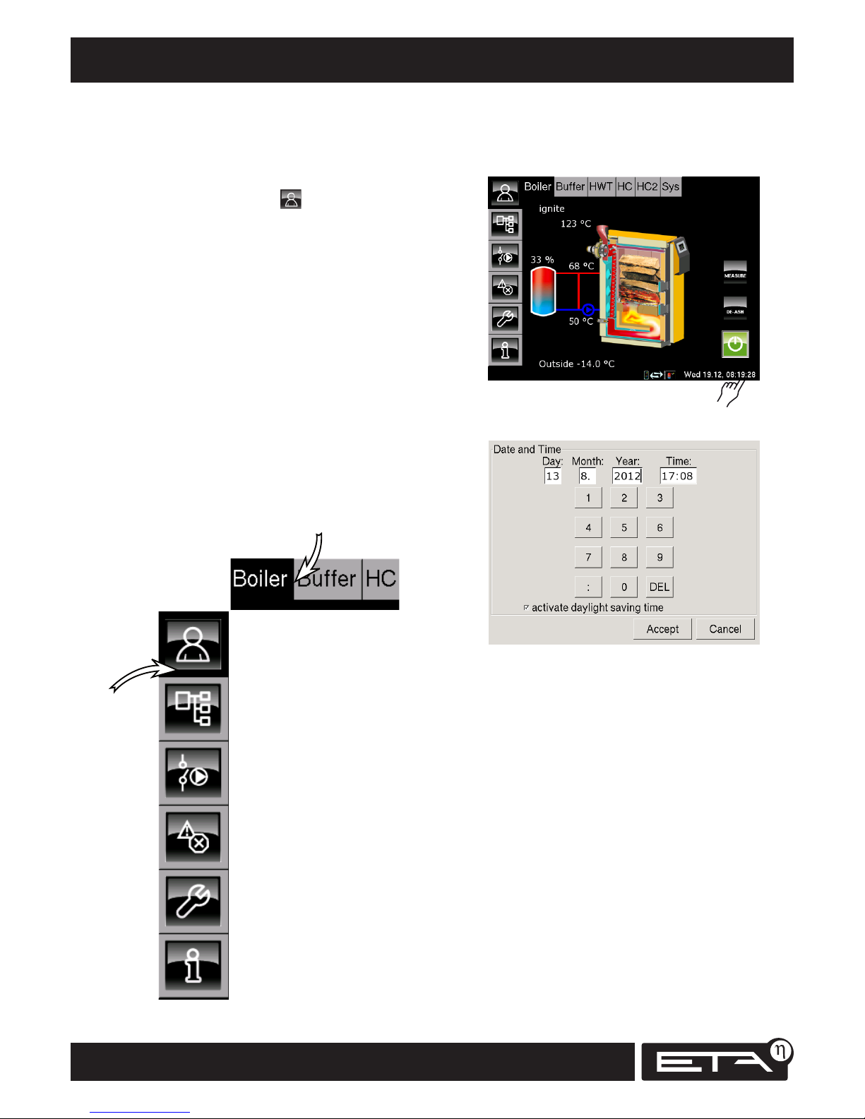
38
www.eta.co.at
Adjusting the date and time User interface
Getting to know the control system
Instead of buttons, the touchscreen is operated
using icons directly on the screen.
In order to familiarise yourself with how to operate
the system, tap once on the icon on the left of
the screen.
The touchscreen only displays those function blocks
that are required and configured to work with your
heating system.
You can use the horizontal buttons [Boiler],
[Buffer], [HC], [HWT] ... to flick between the
individual function blocks (FUBs).
These instructions contain descriptions of all the
function blocks of the ETAtouch software.
Moving on the touchscreen
Use the horizontal buttons to select the individual
function blocks (FUBs) of the heating system.
Overview of the selected
function block.
Text menu for adjusting the
parameters of the selected
function block
I/O list allowing experts to
assign inputs and outputs
Toolbox
for experts
INFO
Help
Error messages
for the selected function
block
The vertical buttons are used to open the different views for the
selected function block (FUB):
Adjusting the date and time
Tap on the date or time at the bottom right-hand
corner of the touchscreen.
A screen appears for adjusting the date and time:
Tap on the [Day], [Month], [Year] or [Time] fields to
alter the settings.
Once a field has been filled in by entering
numbers, the cursor automatically moves to the
next field.
[DEL] deletes the number to the left of the cursor.
[Cancel] closes the screen without saving the
changes.
[Accept] saves changes and closes the screen.
Page 39
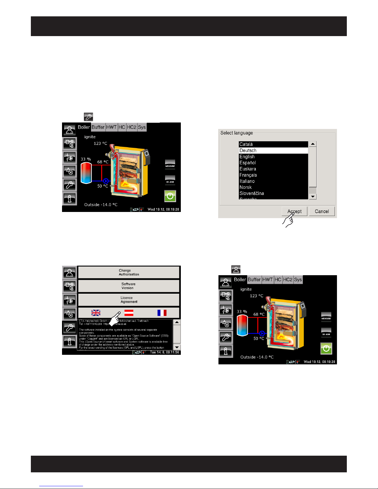
39
2012-11
User interface Changing the language
SH Operation
Changing the language
It is possible to change the language on the screen.
Switching to the toolbox
Press the button to switch to the toolbox.
Tapping the button with the flag symbols
Tap the button with the flag symbols to go to the
language selection screen.
Selecting a language
Select the language you require and
confirm by pressing the [Accept] button.
Back to overview
Press to return to the boiler overview screen.
Page 40
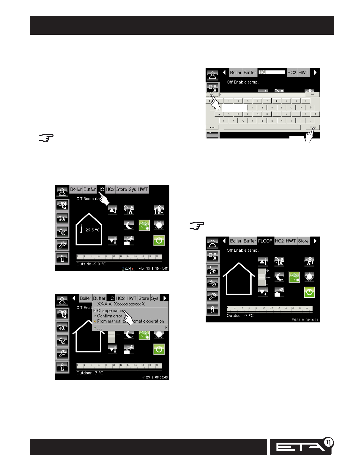
40
www.eta.co.at
Changing function block names User interface
Changing the names of
the function blocks
The names of the function blocks can be changed
at any time in order to make them clearer to you.
For example, the names of the heating circuits HC,
HC2 etc. can be changed to ground floor, upper
floor, parents, living room or similar.
Example: Renaming HC1 "Ground floor"
Even though this example uses a long name, it is
best to choose short names so that you can reach
all the function blocks without having to use the
arrow buttons.
Selecting heating circuit 1
Double-tap [HC] to rename this function block.
2x
A small screen appears for this function block.
Tap the [Change Name] button. An on-screen
keyboard appears.
Changing the name using the keyboard
cancel
save
Use the keyboard to enter the new name for
heating circuit 1, in this example: FLOOR.
Then press the [ENTER] button to save the new
name.
The [ESC] button cancels the renaming process and
changes back to the previous name.
HC has now been renamed "FLOOR".
The names of all the function blocks can be
changed at any time.
Page 41
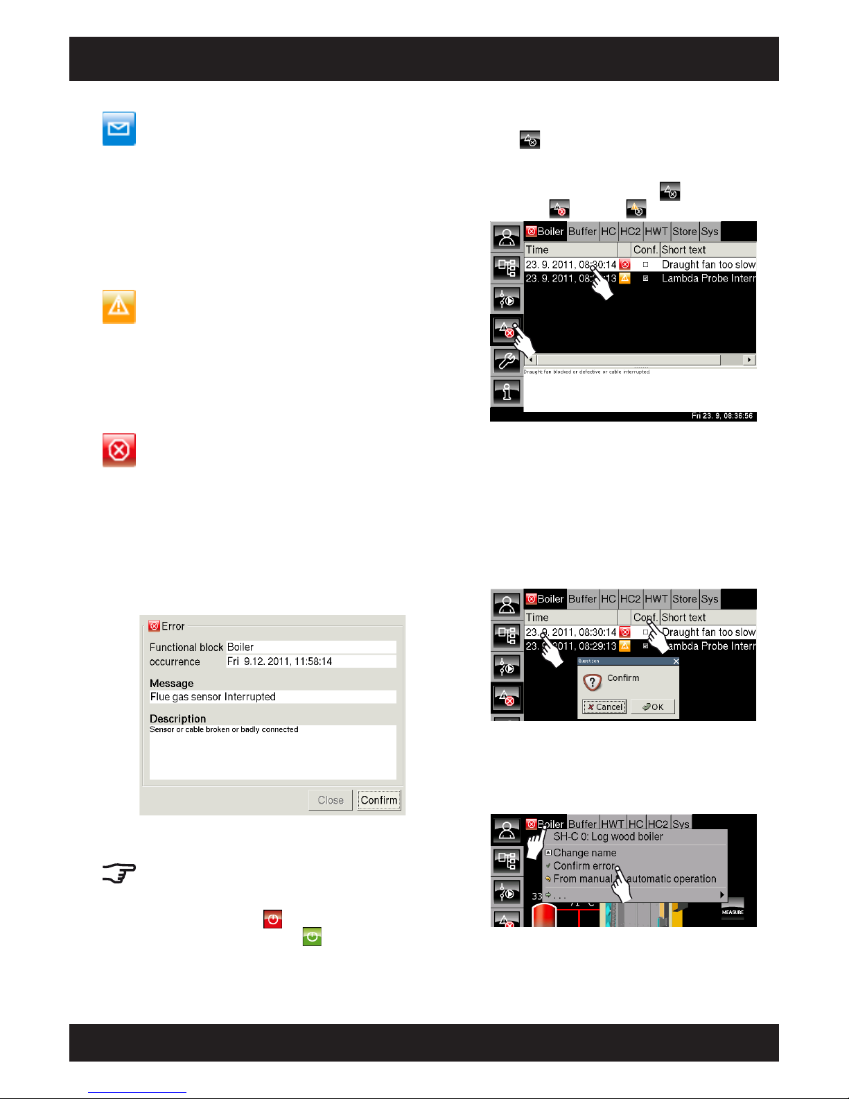
41
2012-11
User interface Alarm, error, warning, message
SH Operation
Message
This icon in the function block buttons indicates a
message. Messages do not interrupt operation of the
boiler, nor must they be acknowledged.
For example, they may indicate that the cleaning
lever should be operated or inform the user of events
outside normal operation, e.g. in summer, the pump
anti-blocking protection begins every Saturday at
noon.
Warning
This icon indicates a warning. Warnings are issued
when a function that is not essential to active operation fails. A warning can be acknowledged before
the error is resolved. However, it will continue to be
displayed until the cause of the error has actually
been dealt with.
Error, alarm
This icon indicates errors or alarms. Alarms are issued
for errors that halt operation. Some can be acknowledged before the error is resolved. However, they
continue to be displayed until their cause has actually
been dealt with.
Some errors and alarms cannot be acknowledged
until they have been successfully resolved. These
messages can be deleted with the [Confirm later]
button.
!!! Restart after an alarm !!!
Once the errors have been resolved and the errors
and alarms have been acknowledged, the boiler or
the affected heating circuit must be switched back on
using the on/off button .
Once they are switched on, the button lights up
green.
Displaying errors
Press to view the list of errors for the currently
selected function block.
If an error, alarm or warning occurs in any
function block, the icon on the button
changes to (alarm) or (warning).
By selecting a line, you can view a help text at
the bottom of the screen.
Acknowledging errors
Select the line and double-tap it or press [Conf.].
A confirmation window appears.
Press "OK" to acknowledge the message and
delete it from the list. Press [Cancel] to close the
window without acknowledging the error.
2x
or
Acknowledging all errors
Double-tap a function block to display a menu
where you can acknowledge all errors by tapping
[Confirm error].
2x
Page 42
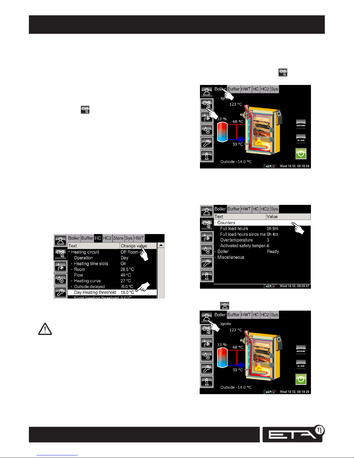
42
www.eta.co.at
Opening the text menu User interface
Example: Displaying the boiler counters
Tap the [Boiler] button to open the "Boiler"
function block.
From the overview screen, press the button to
go to the text menu.
The boiler text menu appears.
Tap the [Counters] line. The submenu opens and
the boiler counters are displayed.
Press the button to return to the overview.
Function block text menus
There is a "text menu" for each function block. This
view shows the current parameter settings. It also
allows the user to make changes.
Opening the text menu
Select the desired function block, e.g. by tapping
[Boiler]. Next, change the view to "text menu" by
pressing the button.
The text menu for the selected function block
appears. The individual parameters for the selected
function block are displayed.
Lines preceded by have a submenu, which can
be opened by tapping the line. The submenu can
be closed again by tapping the upper-level line
that is marked with .
Modifying parameters
It is possible to modify certain parameters in
order to adapt the heating to your needs. Tap
these parameters to select them. The [Value] field
changes and the [Change value] button appears.
Change the parameters by double-tapping on
the line, or select the line and press the [Change
value] button.
or
2x
In case of doubt, consult an expert before
making any changes.
Only modify parameters if you know what their
function is. Read through the corresponding
section of the user manual before making changes.
If the explanation of the relevant function given
in the manual is not sufficient for your purposes,
confer with an expert.
Page 43

43
2012-11
SH Operation
Page 44
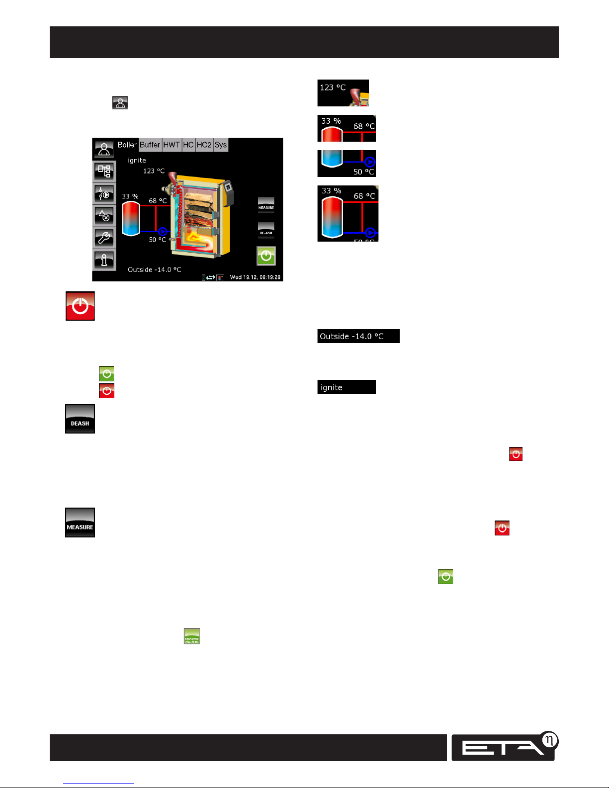
44
www.eta.co.at
Overview, buttons, functions Log boiler [Boiler]
Boiler overview
Press and [Boiler] to open the Boiler overview
screen. The overview screen shows you the boiler
mode and buffer charging status at a glance.
On/off button
The on/off button serves only to switch off the
boiler. The boiler is switched on by opening the
insulating door.
Green = On
Red = Off
De-ash button
If this button is pressed during boiler operation,
the boiler will perform a complete ember burnout
(duration ~1 hour). All embers and ash are burned
to make subsequent cleaning easier. Pressing this
button again during operation ends the burnout.
Emission measurement
The boiler must already have started up in order to
operate this button. This switches the boiler into
emission measurement mode and operates it
for 30 minutes at full load. The control system
ensures that sufficient heat is channelled to the
buffer, the heating circuits and the hot water tank.
In emission measurement mode, the button shines
green and a countdown for the emission
measurement mode is displayed. After 30 minutes,
all pumps and valves are automatically switched
back to automatic mode.
Exhaust gas temperature
Boiler flow temperature
Boiler return temperature
Buffer storage tank and charging
status
The buffer storage tank and the pump icon are
displayed as soon as the boiler pump is switched
on and heat is being supplied to the buffer storage
tank. The percent display shows the current buffer
charging status.
Outside temperature
The current outside temperature is measured by
the installed outside temperature sensor.
Operating mode
This line shows the boiler's current operating
mode. The possible modes are listed below.
Ready
The boiler is switched off. The on/off button
shines red. The boiler can be started up at any
time.
Ignite
See "Start-up" chapter. In ignite mode, the boiler
can also be switched off with the on/off
button.
Heating
The boiler is switched on and the insulating
door is closed. The boiler is supplying heat to the
buffer storage tank.
Ember burnout
The fuel in the boiler is almost consumed and the
exhaust gas temperature is below 80°C. If the ash
button was pressed during boiler operation, the
boiler will perform a complete ember burnout for
subsequent cleaning.
Page 45

45
2012-11
Log boiler [Boiler] Overview, buttons, functions
SH Operation
switched off because the control system assumes
that the log boiler is to be started up. A corresponding message is displayed.
Malfunction
There is a malfunction in the draught fan, the
exhaust gas temperature sensor or the boiler
temperature sensor. The boiler may not be
started up in this mode.
Calibrating lambda probe
After every 500 hours of full-load operation,
the boiler performs an automatic calibration of
the lambda probe. This always occurs after an
ember burnout and only at night between 23:00
and 04:00. This calibration can also be initiated
manually by opening the primary and secondary
air valves and flushing the boiler with fresh air
using the draught fan. If the boiler has not been
started up for over 48 hours, this calibration takes
only 30 minutes. If the boiler was in operation
until recently, the calibration can take up to 3
hours. If the boiler is started up during calibration,
the calibration is aborted and started again 9 days
later.
Insulation door open
The insulation door is open. If the boiler was previously in heating mode, it switches back to heating
mode after the insulation door is closed. For all
other modes, the boiler switches to ignite mode
after "Insulation door open". If the insulation door
stays open for more than 30 minutes, an error
message is displayed and (depending on setting)
an audible signal emitted.
Overtemperature
The boiler temperature is over the temperature
of 90°C set for [Boiler max]. The draught fan is
switched off and an error message indicates that
less fuel should be added in future. Once the boiler
has cooled below 86°C, the draught fan switches
on again and heating resumes.
TWIN in operation
This is only displayed if a TWIN burner (pellets) is
installed on the log boiler.
"TWIN in operation" mode displayed as soon as the
buffer needs heat and the log boiler is unable to
provide it. Then the control system starts the TWIN
burner to supply heat to the buffer. The current
status of the TWIN burner is shown in the [TWIN]
FUB.
If the log boiler's insulation door is open for more
than 1 minute, the TWIN burner is automatically
Page 46
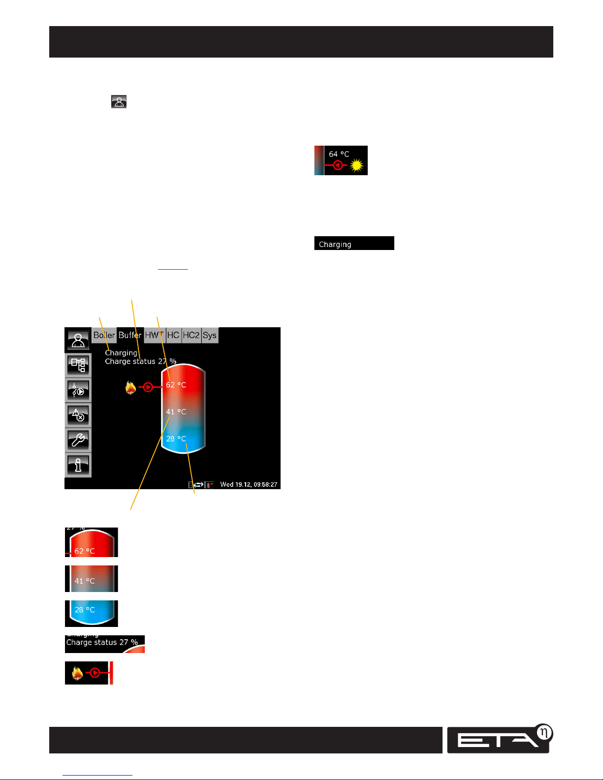
46
www.eta.co.at
Overview, buttons, functions Buffer
Buffer overview
Press and [Buffer] to open the Buffer overview
screen. The overview shows the current temperatures, the operating mode and charging status of
the buffer.
If the buffer is a combination tank (buffer with
built-in hot water tank), the hot water temperature is also displayed. The display also shows the
charge from a solar heating system.
How the buffer works
The current charging status is calculated using the
3 temperature sensors on the buffer. It is needed
to determine the correct amount of firewood to
add. The table on page 11 shows how much
wood should be added.
Buffer top
Buffer middle
Buffer bottom
Operating mode
Buffer charging status
[Buffer top] temperature
[Buffer middle] temperature
[Buffer bottom] temperature
Buffer charging status
Charging by boiler
This icon is displayed when the buffer is being
charged by the log boiler.
With a "combination tank", the icon is shown at
the top of the buffer when hot water rapid charge
is active. If the buffer is only being charged below
the hot water section, this icon appears in the
middle of the buffer.
Charging by solar heating system
This icon for solar charging indicates that the buffer
is being charged by the solar heating system. The
current solar panel temperature is shown above
the icon.
Current operating mode
This line shows the current operating mode of the
buffer. Below is a list of the possible modes:
Demanding
The buffer is demanding heat from the boiler. If the
boiler is switched on, this causes it to start up.
Charging
The boiler is supplying heat to the buffer.
Charged
The buffer switches to charged mode when the log
boiler is supplying heat and 80°C has been reached
at the top of the buffer (= [Target temperature]
factory setting).
If the log boiler is not supplying heat, the buffer
can also reach the charged state if the [Buffer
target 1] temperature is exceeded in the buffer.
Heat dissipation
After a combustion phase, residual heat from the
boiler is channelled to the buffer or, if the boiler
overheats, heat from the boiler is transferred to the
buffer so the boiler can be cooled.
Freeze protection
A temperature sensor in the buffer has fallen
below the freezing protection temperature (factory
setting: 10°C).
Sensor failure
A temperature sensor in the buffer is defective.
View the list of error messages to find out which
sensor is affected.
Page 47
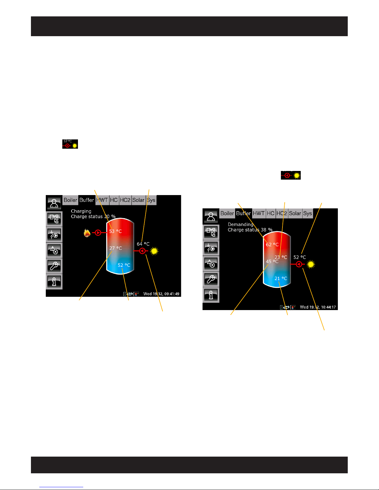
47
2012-11
Buffer Buffer with solar
SH Operation
Different overviews depending
on configuration
The way the buffer and the temperatures are
displayed on the screen differs depending on the
configuration of the heating system.
Buffer with a solar heating system
If the current solar panel temperature is 5°C
(factory setting) higher than the Buffer bottom
solar temperature, the solar heating system begins
to charge the buffer. The icon for solar charging
appears together with the current solar
panel temperature.
If the solar panel temperature falls below the
Buffer bottom solar temperature, the solar coll-
ector pump is switched off.
Buffer top
Buffer bottom Buffer bottom solar
Solar panel temperature
Solar panel is charging buffer
Buffer with solar heating system and stratified
charging valve
The stratified charging valve toggles solar
charging between the top and bottom sections
of the buffer. With this function, the temperatures
"Buffer top solar" and "Buffer bottom solar" are
continually compared with the current solar panel
temperature.
First the top is always charged as soon as the solar
panel temperature is higher than the Buffer top
solar temperature.
After reaching the Buffer target temperature,
charging switches to Bottom until the Buffer
target temperature has also been exceeded at the
bottom.
The icon for solar charging is shown at the
top or in the middle of the buffer, depending on
the position of the stratified charging valve.
Buffer top
Buffer bottom Buffer bottom solar
Solar panel
Buffer top solar
Solar panel is charging top section of buffer.
The stratified charging valve is in the top
position.
Icon in the middle: buffer is being charged in
bottom section. The stratified charging valve is in
the bottom position.
Page 48
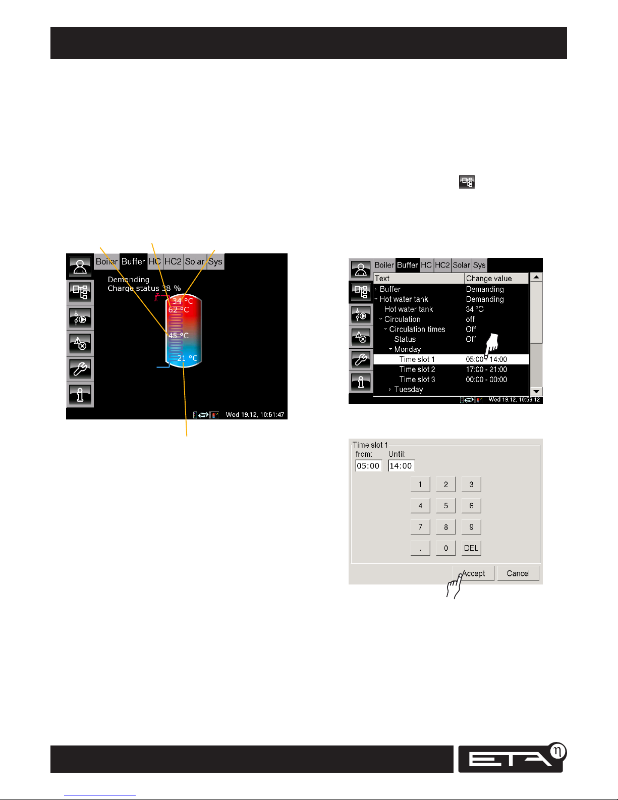
48
www.eta.co.at
Combination tank with solar Buffer
Switching times for circulation pump for
combination tanks only adjustable in text menu
With combination tanks, there is also the option
of controlling a circulation pump. No timer for the
circulation pump is displayed in the overview.
Switching times for the circulation pump must be
adjusted in the text menu.
In the Buffer overview, press to open the text
menu. Tap the [Hot water tank] line and, in the
submenu, tap the [Circulation] line.
Tap the [Circulation times] line. Time slots for the
circulation pump can only be set on an individual
basis for each day of the week.
2x
Double-tap the desired time slot. A screen appears
for setting the time slot:
Time slots for the circulation pump can now be
changed.
Press [Accept] to save the new settings. Use the
same method to adjust the time slots for all other
days of the week.
Combination tank with a solar heating system
There are different types of combination tank. A
hot water tank can be installed in the top section
of the buffer, an internal water heat exchanger
may be integrated throughout the entire height
of the buffer, or a third-party fresh water module
may be installed.
For all these variants, the overview always shows
an internal water heat exchanger and the hot
water temperature at the top of the buffer is
displayed.
Buffer top
Buffer bottom solar
Temperature of
hot water tank
Buffer bottom
Page 49
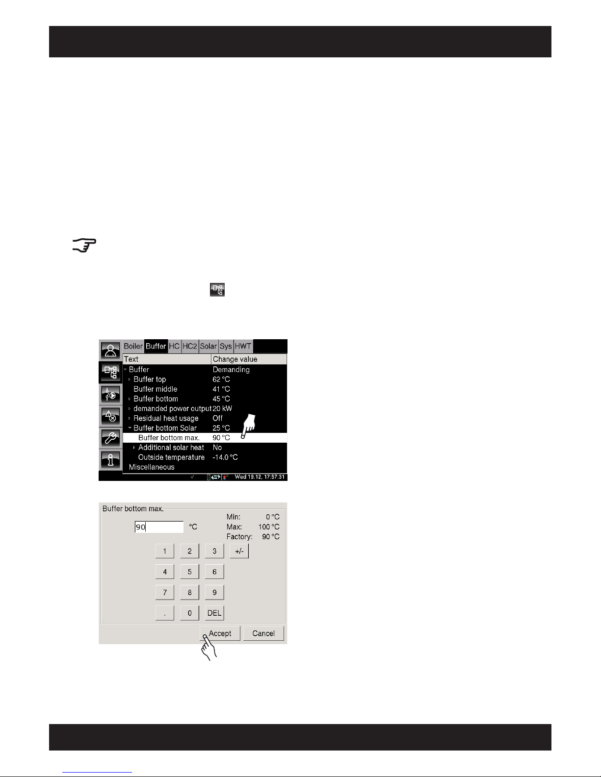
49
2012-11
Buffer "Buffer bottom max." for solar heating systems
SH Operation
"Buffer bottom max." switch-off temperature
(solar heating systems only)
The "Buffer bottom max." switch-off temperature
can only be set when the solar heating system is
charging the buffer. This adjustable temperature
sets a threshold for how much the buffer can
be charged by the solar heating system in order
to prevent the buffer from overheating.
If the Buffer bottom solar sensor reaches the
adjustable Buffer top max. temperature, the solar
collector pump on the solar heating system is
switched off.
The factory setting for the "Buffer bottom max."
temperature is 90°C.
Changing the "Buffer bottom max." temperature
Press the buttons [Buffer] and to open the
text menu. Tap the [Buffer] line and then, in the
submenu, tap [Buffer bottom solar].
Double-tap the [Buffer bottom max.] line.
2x
A settings screen opens:
Enter the new temperature and press [Accept]. The
text menu display appears again.
Page 50
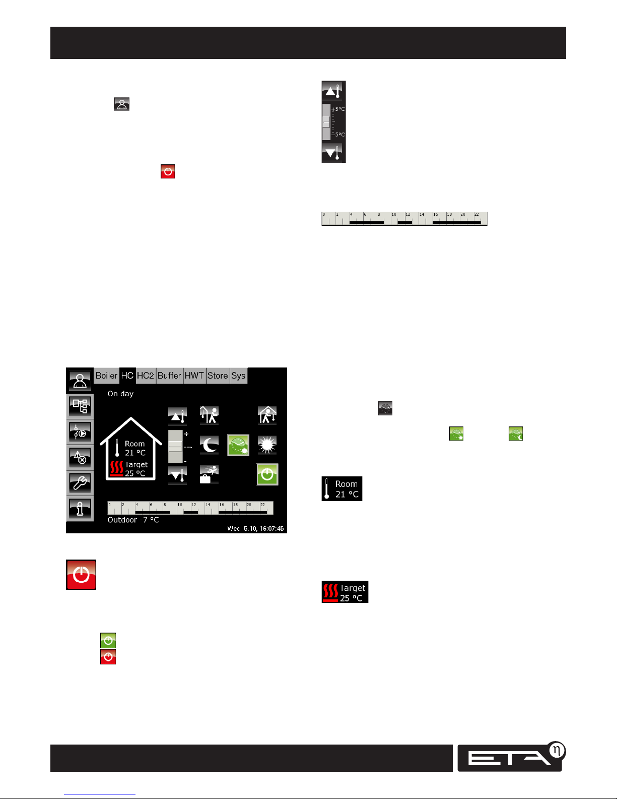
50
www.eta.co.at
Overview, buttons and functions Heating circuit
Slider
The slider is only shown if there is no room
temperature sensor installed. The slider can be
used to change the room temperature by approx.
+/- 5°C.
Please bear in mind that this substitute function
cannot replace the precision of a room sensor.
Timer
The timer shows the set heating time slots for
the current day of the week. Tapping this timer
brings up a screen where it is possible to set 3 time
slots for each day of the week.
If a room sensor is installed, the desired room
temperature can be set for each time slot.
Likewise, the reduced room temperature (set-back
temperature) between the heating time slots can
also be adjusted.
Within a set time slot, the heating circuit will be in
"Day" mode. Outside of the time slots, it will be in
"Night" mode.
If the heating circuit is operated in "Auto"
mode ( button), this button changes
the icon depending on whether the heating
circuit is running at "Day" or "Night"
temperature.
Current room temperature
(room sensor only)
Only displayed if a room sensor is installed
for this heating circuit. This displays the current
room temperature as measured by the room
sensor.
Current flow temperature
The current target flow temperature for the heating
circuit is only displayed if the heating circuit is
switched on and in operation.
"Heating circuit" overview
Press and [HC] to open the "Heating circuit 1"
overview screen.
Each heating circuit has its own function block
(HC2, HC3...).
In the overview of the selected heating circuit,
the on/off button can be used to switch the
heating circuit on and off.
The timer can be used to set 3 different time slots
for each day of the week. If there is a room sensor
installed, you can also adjust the desired room
temperature.
If not, a slider on the overview screen allows you
to adjust the room temperature.
"Day" and "Night" mode
During the time slots, the heating circuit is in
"Day" mode.
Outside the time slots, the heating circuit is in
"Night" mode.
Heating circuit on/off
This button is used to switch the heating circuit on
and off.
The boiler has a separate on/off button.
Green = Heating circuit on
Red = Heating circuit off
Page 51
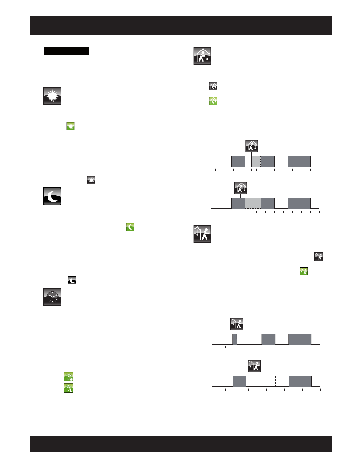
51
2012-11
Heating circuit Overview, buttons and functions
SH Operation
Come
This function is only available in "Auto" mode.
Regardless of the current time slot, pressing the
button (when you come home) switches the
heating circuit to "Day" mode (button lights up
) until the next set time slot.
If the unit has a built-in room sensor, the heating
circuit is regulated to the set room temperature. If
there is no room sensor, the heating circuit runs
using the heating curve "Day".
0 3 6 9 12 15 18 21 24
0 3 6 9 12 15 18 21 24
Das Drücken von „Kommen“ in
einer Heiz-Pause heizt bis zu Ende
des folgenden Heiz-Zeitfensters.
Das Drücken von „Kommen“ während
eines Heiz-Zeitfensters überspringt die
folgende Absenkphase (heizt durch).
When “Come” is pressed during a heating
break, heating continues until the end of
the following heating time slot.
When “Come” is pressed during a heating time
slot, heating continues on through the following
reduced heating phase.
Go
This function is only available in "Auto" mode.
Regardless of the current time slot, pressing the
button (when you go out) switches the heating
circuit to "Night" mode (button lights up ) until
the next set time slot.
If the unit has a built-in room sensor, the heating
circuit is regulated to the stored set-back temperature. If there is no room sensor, the heating circuit
runs using the heating curve "Night".
0 3 6 9 12 15 18 21 24
0 3 6 9 12 15 18
21 24
0 3 6 9 12 15 18 21 24
0 3 6 9 12 15 18 21 24
Das Drücken von „Gehen“ während
eines Heiz-Zeitfenster senkt ab bis
zum Beginn des nächsten Zeitfensters.
Das Drücken von „Gehen“ in
einer Heiz-Pause überspringt
das nächste Heiz-Zeitfenster.
Das Drücken von „Kommen“ in
einer Heiz-Pause heizt bis zu Ende
des folgenden Heiz-Zeitfensters.
Das Drücken von „Kommen“ während
eines Heiz-Zeitfensters überspringt die
folgende Absenkphase (heizt durch).
When “Go” is pressed during a heat ing time slot,
heating is reduced until the start of the next
time slot.
When “Go” is pressed during a
heating break, the next heating time
slot is bypassed.
Outdoor -13°C
Current outside temperature
The current outside temperature is measured by
the built-in outside temperature sensor.
Constant "Day" mode
This button can be used to switch the heating
circuit to constant "Day" mode (button lights
up ).
If a room sensor is installed, the temperature will
be regulated to the highest room temperature
set for that day in the timer. If there is no room
sensor, the heating circuit runs using the heating
curve "Day".
"Auto" and "Night" modes can be ended by
pressing the button.
Constant "Night" mode
This switches the heating circuit to constant
"Night" mode so that it runs at the set-back
temperature (button lights up ).
If there is a built-in room sensor, the temperature
is regulated to the set-back temperature that is
set in the timer. If the unit does not have a room
sensor, the heating circuit runs using the heating
curve "Night".
"Auto" and "Day" modes can be ended by pressing
the button.
"Auto" mode
"Auto" mode automatically switches between
"Day" and "Night" mode.
Within a set time slot, the heating circuit will be in
"Day" mode. Outside of the time slots, it will be in
"Night" mode.
The "Auto" display changes the icon depending
on whether the heating circuit is currently in "Day"
or "Night" mode.
"Day" mode
"Night" mode
Page 52
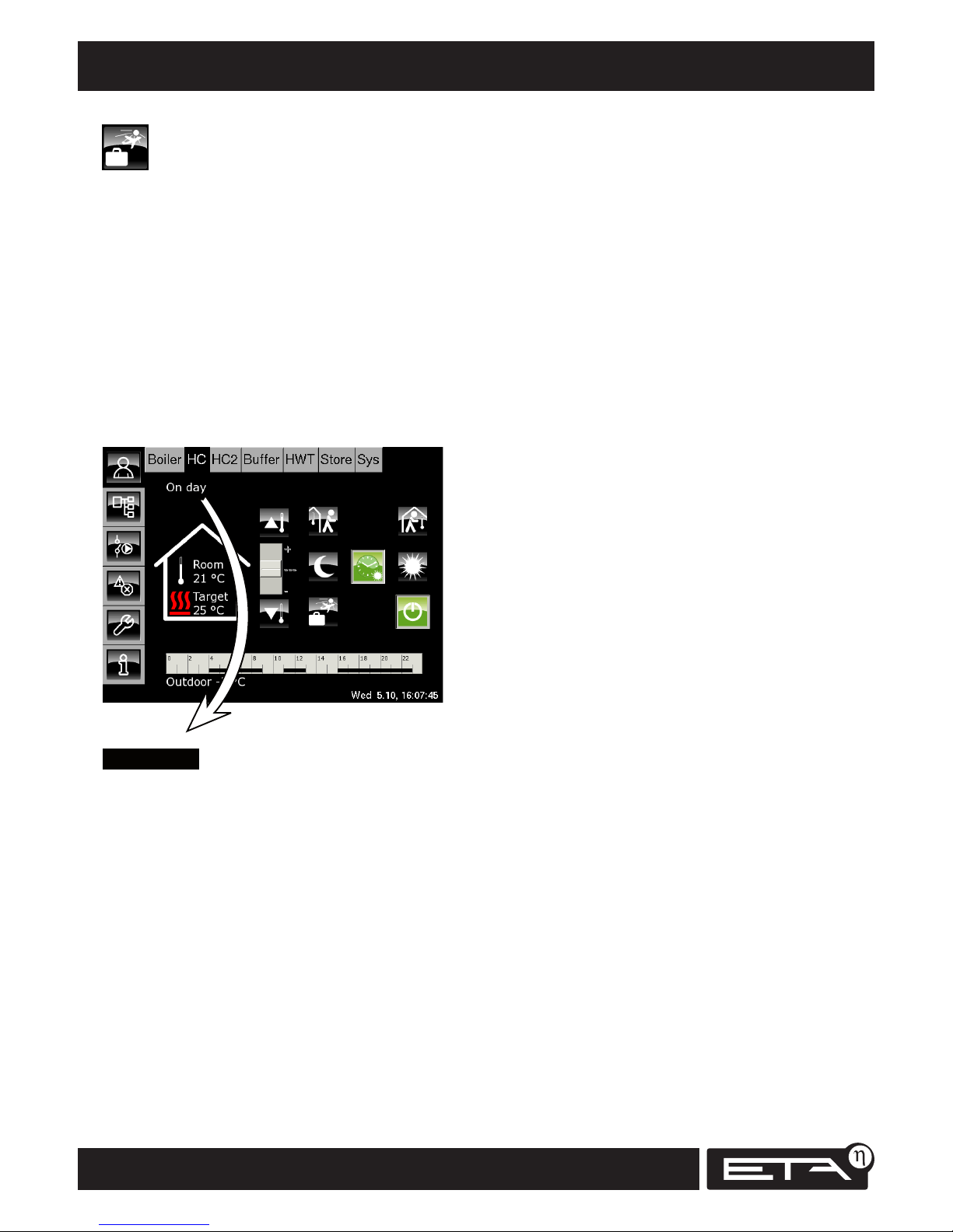
52
www.eta.co.at
Operating modes Heating circuit
On Night
The heating circuit is outside of the timer's time
slots and in "Night" mode.
The flow temperature of the heating circuit is regulated using the "Heating curve night".
If the unit has a built-in room sensor, the temperature is regulated to the stored "set-back temperature". The switch can be in either the "Auto" or
the "Night" position.
Holiday On
The heating circuit is switched on and in holiday
mode (= constant "Night" mode). It remains in this
state until the "End of holiday" date.
On Delay
The heating circuit is no longer demanding any
heat and is in delay mode. The boiler pump is still
running for a short time in order to channel the
heat out of the boiler.
On Freezing room
The heating circuit is in operation because the
current room temperature is below the freezing
protection temperature (10°C).
On Freezing flow
The heating circuit is in operation because the
current flow temperature is below the freezing
protection temperature (10°C).
On Heat dissipation
The heating circuit is in operation in order to cool
the boiler by dissipating excess heat. Also displayed
during emission measurement.
On Overtemperature
The heating circuit is in operation because the
boiler is running at overtemperature. The heating
circuit is running at the highest set flow temperature in order to dissipate the heat from the boiler
(overheating protection).
Holiday mode
The "Holiday" button is used to set a period for
which the selected heating circuit will run in
"Night" mode.
Any adjustments made to the room temperature
also influence the "Day" temperature, and thus
the temperature for heating up at the end of the
holiday. As such, it is best not to adjust the room
sensor for holiday set-back.
If you wish to reduce the room temperature, you
can set an individual "set-back temperature" in the
timer. During "Holiday" mode, the lowest of all
the "set-back temperatures" in the timer is the
one that applies.
On Day
Current operating mode
This line shows the current operating mode of
the heating circuit. Below is a list of the possible
modes:
On Day
The heating circuit is within one of the timer’s
time slots and in “Day” mode.
The flow temperature of the heating circuit is regulated using the “Heating curve day”.
If the unit has a built-in room sensor, the temperature is regulated to the highest room temperature set for the time slot. The switch can be in
either the “Auto” or the “Day” position.
Page 53

53
2012-11
Heating circuit Operating modes
SH Operation
On Screed
The heating circuit is in operation; the screed
drying program is being run.
Off Enable temp.
The heating circuit is still switched off because the
boiler is not yet able to supply sufficient heat. The
enable temperature for the heating circuit has not
yet been exceeded.
Off Target day
The heating circuit is switched off. The target flow
temperature calculated from the heating curve
"Day" is below the room temperature as measured
by the room sensor.
If the unit does not have a room sensor, the calculated target flow temperature is below 18°C.
Off Target night
The heating circuit is switched off. The target
flow temperature calculated from the heating
curve "Night" is below the room temperature as
measured by the room sensor.
If the unit does not have a room sensor, the calculated target flow temperature is below 18°C.
Off Target holiday
The heating circuit is within the set holiday time,
and thus switched off.
The target flow temperature calculated from the
heating curve "Night" is below the room temperature as measured by the room sensor.
If the unit does not have a room sensor, the calculated target flow temperature is below 18°C.
Off Room day
The heating circuit is within a time slot, but
switched off. The current room temperature is
higher than the set "Room target" temperature by
at least the "RoomOffDiff" temperature.
Off Hot water
The heating circuit is switched off because the hot
water is currently being heated.
Off Room night
The heating circuit is switched off and outside the
set time slots. The current room temperature is
higher than the stored set-back temperature by at
least the "RoomOffDiff" temperature.
Off Room holiday
The heating circuit is within the set holiday time,
and thus switched off. The current room temperature is higher than the stored set-back temperature
by at least the "RoomOffDiff" temperature.
Off Outside day
The heating circuit is switched off. The current
outside temperature is higher than the set temperature for "Day Heating threshold".
Off Outside night
The heating circuit is switched off. The current
outside temperature is higher than the set temperature for "Night Heating threshold".
Off Outside holiday
The heating circuit is within the set holiday
time, and thus switched off. The current outside
temperature is higher than the stored set-back
temperature.
Off Summer
The heating circuit is switched off. The only active
functions are the freezing protection and the boiler
pump's "anti-blocking protection", which runs at
midday every Saturday.
Off Sensor failure
The heating circuit is switched off due to a defect
in the flow temperature sensor.
Page 54
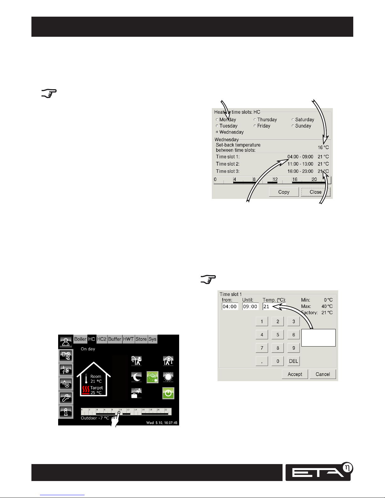
54
www.eta.co.at
Setting the heating time slots Heating circuit
Setting the heating time slots
The heating circuit timer can be used to set 3
different time slots for the heating for each day of
the week.
If the unit has a room sensor, a target room
temperature can also be set for each time slot.
Likewise, the reduced room temperature (set-back
temperature) between the heating time slots can
also be adjusted for each day of the week.
"Day" mode
During a set time slot, the heating circuit is in
"Day" mode.
If a room sensor is installed, this regulates the
heating circuit to the set target room temperature
for the time slot.
If there is no room sensor, the flow temperature
of the heating circuit is calculated using the
heating curve.
"Night" mode
Outside the time slots, the heating circuit is in
"Night" mode.
If a room sensor is installed, this regulates the
heating circuit to the stored "set-back temperature" for the time slot.
If there is no room sensor, the flow temperature of
the heating circuit is calculated using the heating
curve.
Adjusting the timer (with room sensor)
In the overview for the selected heating circuit, tap
the timer. The screen for setting the timer opens.
Overview of current time slots
The current day of the week is selected automatically. The set time slots for the current day of the
week are shown on the screen.
Days of the week
Room temperature only
Set-back temperature
between time slots
3 adjustable time slots
for each day of the week
Target room temperature
room sensor only
Selecting a time slot
Tap the [Time slot 1] line. The time slot setting
screen opens.
The times for “Day” mode can now be altered.
If the unit has a built-in room sensor,
the target room temperature can also be set.
Room
sensor only
Press [Accept] to save the new settings. Use the
same method to adjust the other time slots.
Page 55
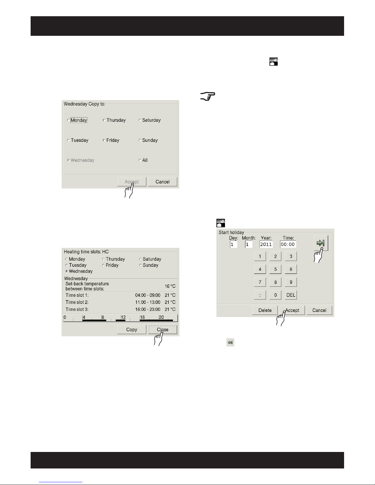
55
2012-11
Heating circuit Setting the heating time slots
SH Operation
Copying time slots to other days of the week
Once the time slots have been adjusted, they can
also be adopted for other days of the week.
In the time slot overview screen, tap the [Copy]
button. A screen appears for selecting a day of the
week:
Tap to select the desired day of the week or [All]
and then press [Accept]. The time slots are adopted
for the selected days.
The new time slots are displayed.
Finally, press [Close].
The heating circuit overview reappears.
"Holiday" function
With this function, the button can be used to
switch the heating circuit to constant "Night"
mode for an adjustable time period. This setting
only ever applies for the selected heating circuit.
The hot water supply from the hot water tank
or the fresh water module is not affected by the
"Holiday" function.
For "Holiday" mode, the heating circuit is regulated
to the lowest set-back temperature set in the timer.
If you wish to reduce the temperature for the
"Holiday" time period, you can set an individual
set-back temperature in the timer.
Adjusting the room sensor also affects the "Day"
temperature when heating up at the end of the
holiday. As such, it is best not to adjust the room
sensor for holiday set-back.
Setting a "Holiday" time period
In the "Heating circuit" overview screen, tap the
button. A screen opens:
Enter the time for the beginning of your holiday.
The button can be used to switch between the
"Start" and "End" of the holiday.
Enter both times and press [Accept].
The heating circuit overview reappears.
Page 56
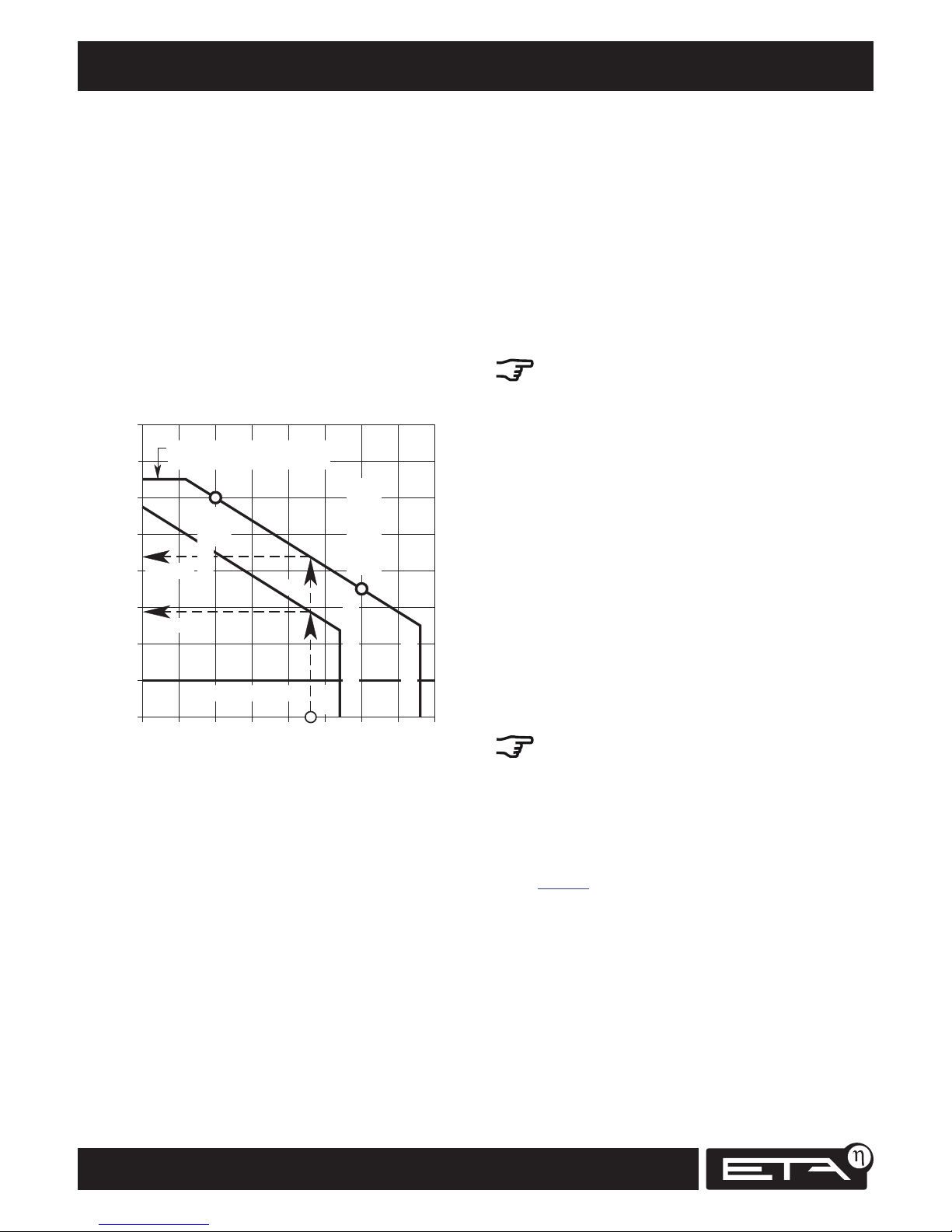
56
www.eta.co.at
The heating curve Heating circuit
Heating curve "Day"
During a set time slot, the heating circuit is in "Day"
mode. The heating curve for "Day" mode can be
adjusted using the parameters "Flow at -10°C" and
"Flow at +10°C". The control system uses these
parameters to plot a line: the heating curve "Day".
The heating curve "Day" and the current outside
temperature are used to calculate the required flow
temperature for the heating circuit. Example:
at +3°C outside temperature => 44°C flow
at -5°C outside temperature => 54°C flow
If the unit has a room sensor, the calculated
flow temperature is corrected. The actual flow
temperature may be higher or lower.
Heating curve "Night"
Outside the set time slots, the heating circuit is in
"Night" mode.
The heating curve "Night" is set back from the
heating curve "Day" by the adjustable value "Setback". The heating curve "Night" and the current
outside temperature are used to calculate the
required flow temperature.
Factory settings for the heating circuit
With software versions 1.20.0 and higher,
the system configuration for the heating circuit
offers the user a choice between underfloor and
radiator heating.
This choice pre-sets some of the parameters in the
heating circuit. For information on these parameters and their factory settings, see
page <?>.
58.
The heating curve
The heating curve controls the flow temperature
for the "Day" and "Night" modes of the heating
circuit in question. During a set time slot, the
heating circuit is in "Day" mode. Outside the time
slots, the heating circuit is in "Night" mode.
Each heating circuit has its own heating curve,
as underfloor heating requires different settings to
radiator heating.
The diagram shows a heating curve for radiator
heating. If the control settings have been adapted
to your system, lower heating curves may be
set for underfloor heating and higher heating
curves for radiator heating.
0
30
20
10
Heating flow temperature (°C)
-20 -10-15
80
70
60
50
40
+10+50-5 +2
0
+15
Outside temperature (°C)
+3°C
Winter set-point
Transition period
set-point
Day
Night
Night heating limit
Day heating limit
Maximum flow temperature
(adjustable with SERVICE permission)
44°C Day
29°C Night
Freezing protection
Maximum flow temperature
This limit protects your heating system.
Underfloor heating is usually limited to 45°C, while
radiators with metal pipes can take temperatures
up to 85°C.
Page 57
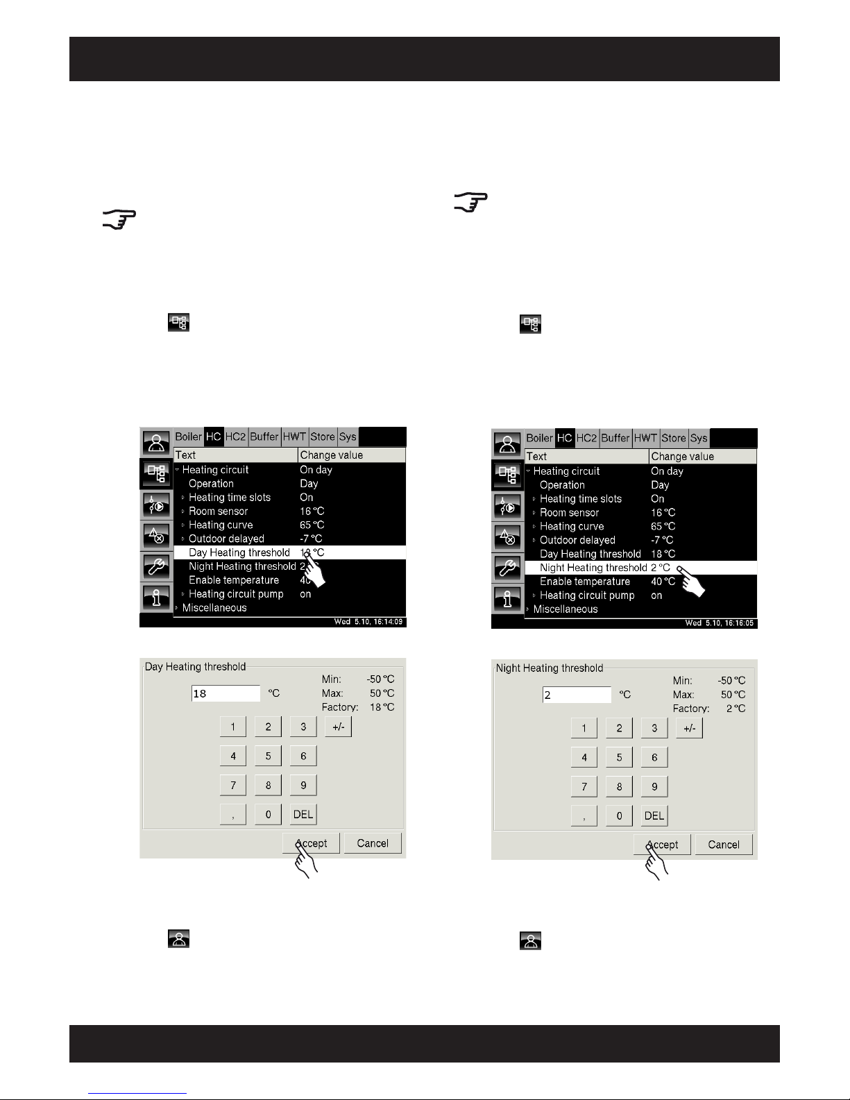
57
2012-11
Heating circuit "Day Heating threshold" and "Night Heating threshold"
SH Operation
The parameter "Day Heating threshold"
With the "Day Heating threshold" parameter, an
outside temperature is set which, when exceeded,
will result in the heating circuit being switched to
"Day" mode.
The factory setting for this parameter is 18°C.
The "Day Heating threshold" can be set
differently for each heating circuit.
Changing the parameter "Day Heating threshold"
Press to open the text menu for the selected
heating circuit.
Tap the [Heating circuit] line to open the submenu.
Double-tap on the [Day Heating threshold] line
(or select the line and press the [Change value]
button).
2x
A settings screen opens:
Enter the new heating threshold for "Day" mode.
Press [Accept] to save the new value.
Press to open the "Heating circuit" overview.
The parameter "Night Heating threshold"
If the heating circuit is in "Night" mode, an outside
temperature is set which, when exceeded, will
result in the heating circuit being switched off.
The factory setting for this value is 2°C.
The "Night Heating threshold" can be set
differently for each heating circuit.
Changing the parameter "Night Heating
threshold"
Press to open the text menu for the selected
heating circuit.
Tap the [Heating circuit] line to open the submenu.
Double-tap on the [Night Heating threshold] line
(or select the line and press the [Change value]
button).
2x
A settings screen opens:
Enter the new heating threshold for "Night" mode.
Press [Accept] to save the new value.
Press to open the "Heating circuit" overview.
Page 58
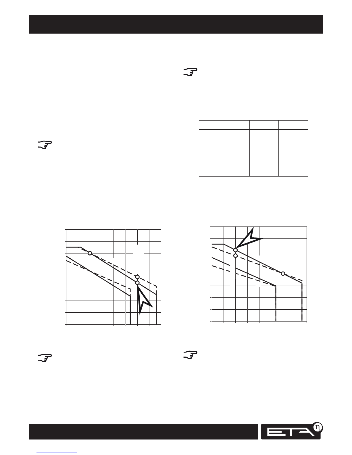
58
www.eta.co.at
Adjusting the heating curve Heating circuit
Adjusting the heating curve
If the heating circuit is always too warm or too
cold, the flow temperature must be adjusted. This
can be done using two parameters:
"Flow at -10°C" and "Flow at +10°C".
No large jumps in temperature
Do not set any large jumps in temperature when
adjusting "Flow at +10°C" and "Flow at -10°C":
For underfloor heating, never more than 2°C
For radiators never more than 4°C
You may need to alter the flow temperatures
again after one or two days, but working in small
steps will help you to set the heating circuits more
precisely, thus saving energy.
During the transition period -> "Flow at +10°C"
If the heating circuit is always too warm or too cold
during the transition period (spring and autumn),
only the flow temperature for "Flow at +10°C" is
reduced or increased.
0
30
20
10
Heating flow temperature (°C)
-20 -10-15
80
70
60
50
40
+10+50-5 +2
0
+15
Outside temperature (°C)
Transition period
set-point
Day
Night
Do not change the flow temperature "Flow at
-10°C" during the transition period.
Factory settings for the
heating circuit
With software versions 1.20.0 and higher,
the system configuration for the heating circuit
offers the user a choice between underfloor and
radiator heating.
This choice pre-sets some of the parameters in the
heating circuit. These parameters and their factory
settings can be seen in the table below:
Preset Underfloor Radiator
Max flow 45°C 65°C
Flow at -10°C 33°C 55°C
Flow at +10°C 25°C 35°C
Set-back 3°C 15°C
Enable temperature 25°C 40°C
Room effect 1°C 4°C
In winter -> "Flow at -10°C"
If the heating circuit is always too cold or too warm
in winter, only the flow temperature
"Flow at -10°" is increased or reduced.
0
30
20
10
Heating flow temperature (°C)
-20 -10-15
80
70
60
50
40
+10+50-5 +2
0
+15
Outside temperature (°C)
Winter set-point
Day
Night
Do not change the flow temperature "Flow at
+10°C" in winter.
Page 59
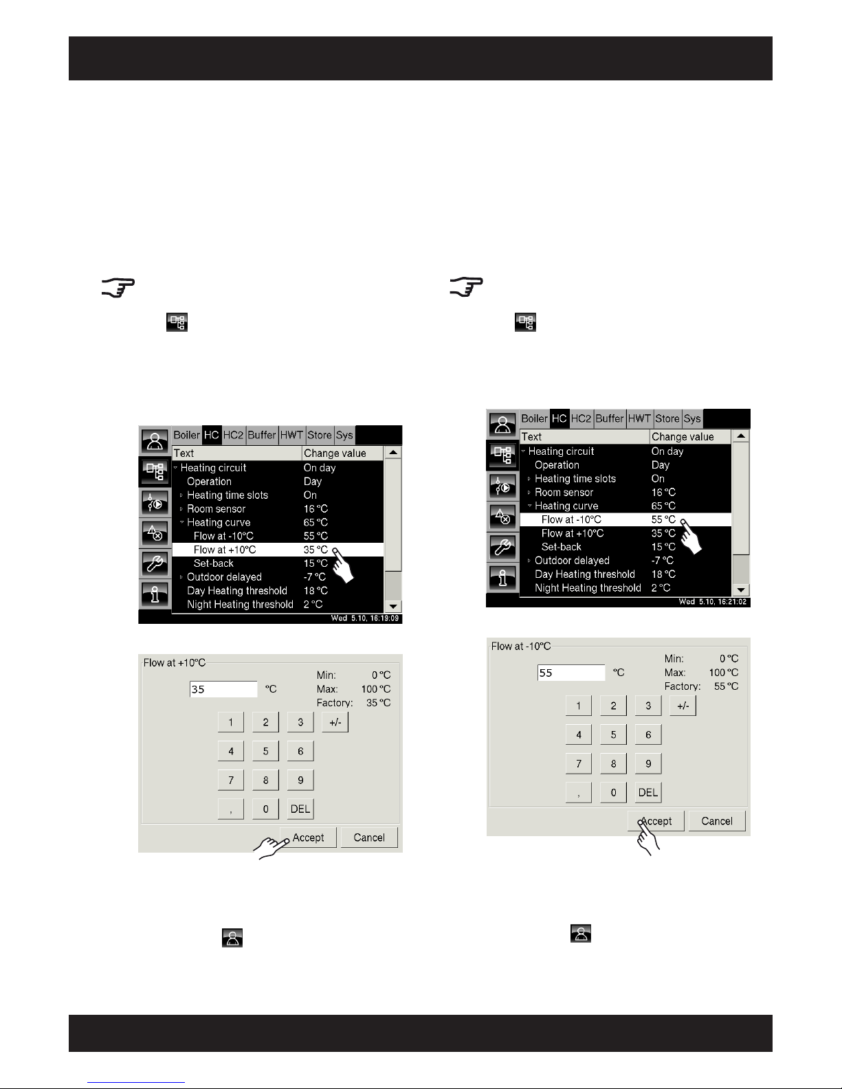
59
2012-11
Heating circuit Adjusting the heating curve
SH Operation
Adjusting the heating curve for outside
temperatures above 0°C -> Changing
"Flow at +10°C"
If the heating circuit is always too cold or too warm
in the transition period, the flow temperature
"Flow at +10°C" is increased or reduced.
No large jumps in temperature
For underfloor heating, never more than 2°C
For radiators, never more than 4°C
Press to open the text menu for the selected
heating circuit.
Tap the [Heating circuit] line and, in the submenu,
tap the [Heating curve] line.
Double-tap on the [Flow at +10°C] line (or select
the line and press the [Change value] button).
2x
A settings screen opens:
Enter the new flow temperature for this heating
circuit. Press [Accept] to save the new value.
The text menu for the selected heating circuit is
displayed. Press to open the "Heating circuit"
over view.
Adjusting the heating curve for outside
temperatures below 0°C -> Changing
"Flow at -10°C"
If the heating circuit is always too cold or too warm
in winter, the flow temperature "Flow at -10°C"
is increased or reduced.
No large jumps in temperature
For underfloor heating, never more than 2°C
For radiators, never more than 4°C
Press to open the text menu for the selected
heating circuit.
Tap the [Heating circuit] line and, in the submenu,
tap the [Heating curve] line.
Double-tap on the [Flow at -10°C] line.
2x
A settings screen opens:
Enter the new flow temperature for this heating
circuit. Press [Accept] to save the new value.
The text menu for the selected heating circuit is
displayed. Press to open the "Heating circuit"
over view.
Page 60
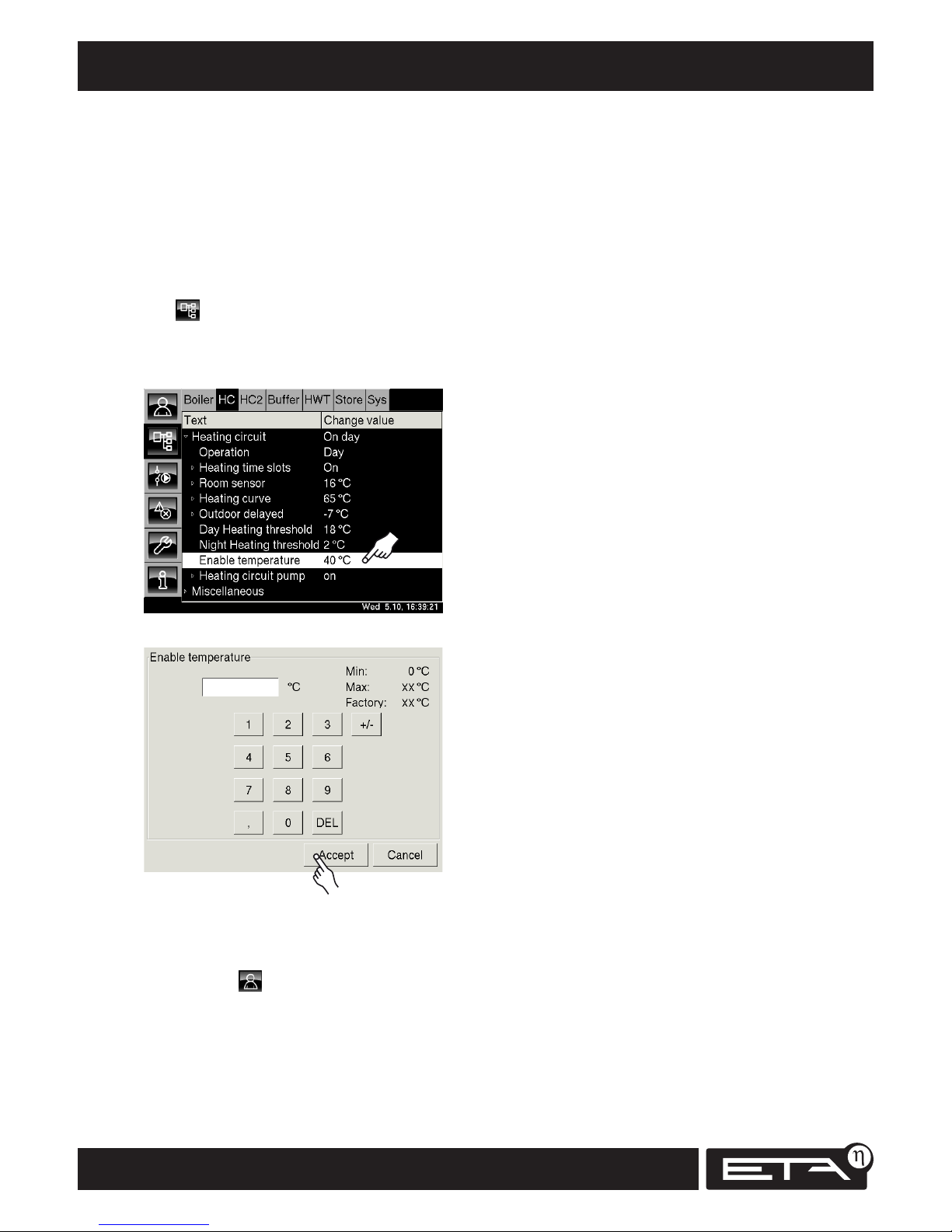
60
www.eta.co.at
Setting the "enable temperature" Heating circuit
Setting the parameter "enable temperature"
The heating circuit pump does not start until the
energy source (buffer or boiler) has exceeded the
"enable temperature". You can give a heating
circuit priority by setting the "enable temperature"
lower than that for all the other heating circuits in
the system.
Opening the heating circuit text menu
Press to open the text menu for the selected
heating circuit.
Tap the line [Heating circuit] and, in the submenu,
double-tap the line [Enable temperature].
2x
A settings screen opens:
Enter the new enable temperature for this heating
circuit. Press [Accept] to save the new value.
The text menu for the selected heating circuit is
displayed. Press to return to the heating circuit
over view.
Page 61
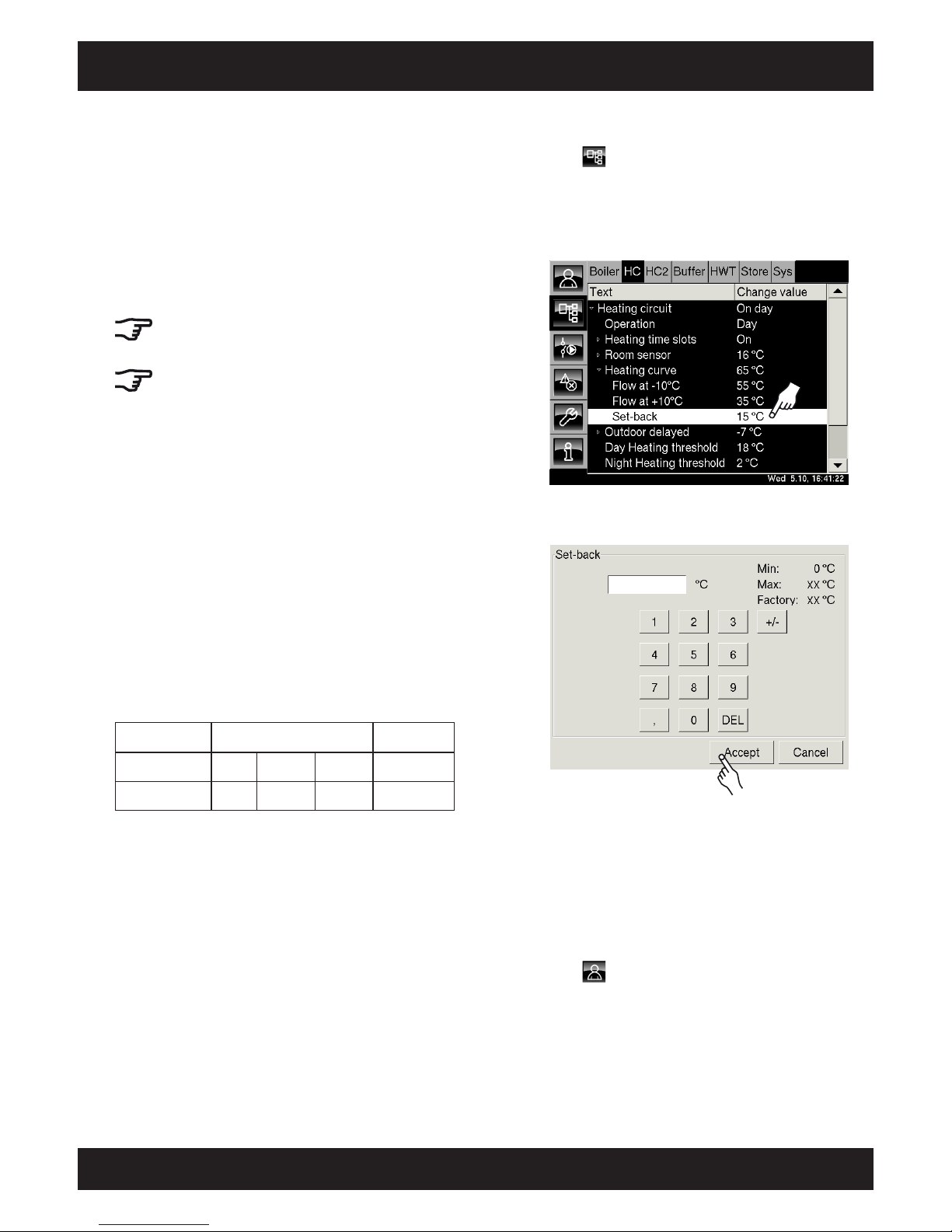
61
2012-11
Heating circuit Adjusting the "Set-back"
SH Operation
Changing the parameter "Set-back"
Press to open the text menu for the selected
heating circuit.
Tap the [Heating circuit] line and, in the submenu,
tap the [Heating curve] line.
Double-tap on the [Set-back] line.
2x
A settings screen opens:
Enter the new temperature difference for the "Setback". Subtracting the "Set-back" from the heating
curve "Day" gives you the heating curve "Night".
Press [Accept] to save the new value. The text
menu for the selected heating circuit is displayed
once more.
Press to return to the heating circuit overview.
The parameter "Set-back"
If the unit does not have a room sensor, the
parameter "Set-back" is used to adjust the night
mode. The control system subtracts the "Set-back"
parameter from the heating curve "Day" to get the
heating curve "Night".
Outside the time slots set in the timer, the heating
circuit is in "Night" mode, and runs using the
heating curve "Night".
The factory setting for this "Set-back" is 15°C.
The "Set-back" can be adjusted for each
heating circuit. The following steps are the same
for all heating circuits.
Do not use large set-backs
Do not overuse "set-back", as much higher air
temperatures will be required to ensure comfort
in the morning if the walls have cooled down too
much overnight. In addition to reducing comfort,
this also wastes the energy saved overnight.
Depending on the "Flow at -10°C" temperature
and the type of heating circuit used (radiator or
underfloor heating), the following guidelines apply
for the set-back:
Temperature
Radiator Underfloor
Flow at -10°C
40°C 60°C 80°C 30-40°C
Set-back
5-8°C 1 0-1 5° C 1 5-2 2° C 3-5°C
Page 62

62
www.eta.co.at
Service and maintenance records
Date
Performed by
Service / maintenance / cleaning
Worked performed / parts replaced
Keep records for service, maintenance or repairs
We recommend that you keep records about all service and maintenance work, as well as malfunctions. These records
can be entered in the following pages.
Then you and our customer service will always have an overview of the work performed on the system.
Page 63
63
2012-11
Service and maintenance records
SH Operation
Date
Performed by
Service / maintenance / cleaning
Worked performed / parts replaced
Page 64

Artikel Nr. der Anleitung SH_Bedienung_Touch_EN
 Loading...