

Page 1

2012-11-08
EN_Englisch
Installation
Log Boiler
20-60 kW
Page 2

2
www.eta.co.at
Conditions for warranty, guarantee, liability 4
Meanings of symbols
Important NOTICES for operation.
CAUTION: Failure to observe these notices can result
in property damage.
STOP: Failure to observe these notices can result in
personal injury.
Conditions for warranty, guarantee, liability ........ 4
Data and dimensions ...................................... 6
Regulations, standards and guidelines ................7
Boiler room .................................................. 8
Electrical connection ....................................... 9
Energy-saving pumps .....................................9
Chimney .................................................... 10
Basics ........................................................ 10
Dimensioning, requirements............................ 11
Requirements, connecting pipe ........................ 12
Water hardness and corrosion ........................ 14
Air venting, compensation, system separation .... 15
Return riser and safety devices ....................... 16
Buffer ....................................................... 17
Hydraulic integration ..................................... 18
Hydraulic integration of several buffers ............... 19
Parallel buffers with internal Tichelmann ............ 20
Parallel buffers with external Tichelmann ........... 21
Serial buffers ............................................... 22
Hydraulic schematic ...................................... 24
Installation ................................................. 26
Minimum clearances for maintenance ................ 26
Air valves for log boilers.................................. 27
Air valves for log boilers with pellet flange ..........29
Draught fan ................................................ 31
Rear wall insulation, door frame ....................... 32
Side panels, boiler control system ..................... 33
Cable duct, flue gas temperature sensor .............. 34
Temperature sensor - flow .............................. 35
Lambda probe, temperature sensor - return ........ 36
Connecting draught fan ................................. 37
Actuators ................................................... 38
Cleaning lever for turbulators ........................... 40
Insulation door, control panel .......................... 41
Panel on top side of boiler ..............................45
Insulation at base of boiler ..............................46
Electrical installation .................................... 48
Terminal diagram ......................................... 48
Checklist for proper installation ....................... 50
Page 3

3
2012-11
Electrical installation 48 Preface
SH Montage
Dear heating technician,
The satisfactory function of a customer's new
heating system depends to a large extent on its
installation. So before starting the installation,
please invest 15 minutes to get an overview with
this manual.
Warranty and guarantee
You should also read the "Conditions for warranty,
guarantee, liability" (see page 4 of this manual)
carefully. All of the requirements we impose are
intended to prevent damage that neither you nor
we wish to occur.
Housing and electrical equipment
will be installed at the end
The electrical equipment and the housing will only
be installed after all piping and installation tasks
have been completed. That helps avoid damage to
these sensitive parts.
Training the customer
To avoid errors in operation, please explain to
your customer (preferably using the user manual)
exactly how the new heating system works and
how it should be operated and maintained.
Extended warranty for commissioning performed
by an authorised partner company
If your newly installed boiler is commissioned by an
authorised partner company or one of our customer
service employees, we offer an extended warranty.
Refer to our warranty conditions in effect at the time
of purchase.
Service agreement
You can ensure the best care by taking out a service
agreement with one of our certified heating system
contractors or our own customer service.
Page 4

4
www.eta.co.at
Conditions for warranty, guarantee, liability
We can only guarantee and accept liability for the
function of our boiler if it is properly installed and
operated.
Requirement for warranty, guarantee and liability
is that this boiler be used in accordance with its
intended purpose, only for heating and hot
water supply with no more than 2,000 fullload hours annually, and, in particular, that the
following general conditions be observed during
installation and operation:
For set-up, a dry room is required. In particular,
only condensation dryers may be used as clothes
dryers in the same room.
Local building and fire protection regulations must
be observed.
The log wood boiler is suitable for use with
air-dried split logs with no more than 20%
water content and wood briquettes. Use with
unsuitable fuels, especially refuse, coal and coke,
and also wet wood, is not permitted.
The combustion air must be free of aggressive
substances such as chlorine and fluorine
from solvents, cleaning agents, adhesives and
propellants, or ammonia from cleaning agents,
to prevent corrosion of the boiler and chimney.
Water is the intended heat-transfer medium. For
special anti-frost requirements, up to 30% glycol
may be added. Softened water is required for
the initial fill-up of the heating system and for
refilling after repairs. For the initial fill-up, the
value of 20,000 lt°dH for the system volume in
litres multiplied by the hardness (in degrees of
German hardness) may not be exceeded. The
pH value should be set between 8 and 9.
Addition of hard water should be minimised to
limit limescale build-up in the boiler. Set enough
shut-off valves to avoid bleeding large amounts of
water during repairs. Any leaks in the system must
be repaired at once.
Ensure a minimum return temperature of 60°C
to the boiler.
A safety valve (3 bar) as protection against excess
pressure and a thermal relief valve (95°C) to
protect against overheating must be installed by
the contractor.
To protect against air suction if the system cools
off, an expert must provide a sufficiently large
expansion tank or a pressure maintenance
system. Sufficient air venting must also be
ensured. Open expansion tanks or underfloor
heating with permeable piping also have a
high air intake, resulting in above-average boiler
corrosion. Corrosion damage to the boiler due to
improper air venting or high air intake is excluded
from warranty, guarantee and liability.
Operation at lower power than the lowest power
specified on the type plate is not permitted.
Only components provided by us may be used
for expansion of the control system, except for
commonly used units such as thermostats.
Cleaning and maintenance are required as
specified in the user manual.
Repairs are only permitted with spare parts
provided by us. The only exceptions are common
standardised parts such as electrical fuses or
fastening materials, as long as they possess
the required features and do not restrict the
functionality of the system.
Page 5

5
2012-11
Conditions for warranty, guarantee, liability
SH Montage
The installing contractor is liable for proper
installation according to the boiler's installation
instructions and the relevant rules and safety
regulations. If you as customer have installed
the heating system partly or entirely without
relevant training and in particular without
up-to-date practical experience, without having
the installation checked by a trained and
responsible expert, we exclude defects in our
delivery and consequential damages resulting
from this cause from our warranty, guarantee and
liability.
For repair of defects carried out by the
customer or by third parties, ETA only bears the
costs or remains obligated by warranty if this work
was approved in advance by the customer service
of ETA Heiztechnik GmbH.
Subject to technical alterations
We reserve the right to make technical
modifications without notice. Printing and
typesetting errors or changes of any kind made
in the interim are not cause for claims. Individual
configurations depicted or described here are only
optionally available. In the event of contradictions
between individual documents regarding delivery
scope, the information in our current price list
applies.
Page 6

6
www.eta.co.at
Data and dimensions
b
c
106
410 (510)
613 (716)>200 >800
263
(362)
>2030 (>2350)
1323 (1504)
208
1472 (1652)
1502 (1684)
1102 (1180)>300
>800
d
a
1712 (1894)
Ø150
SH 20-30 kW (40-60 kW)
Cleaning lever and actuator s can be mounted
left or right sided
a Flow R5/4“ female
b Return R5/4“ female
c Drain R1/2“ female
d Safety heat exchanger R1/2“ male
Wood gasification boiler SH 20 30 40 50 60
Rated capacity kW 10 - 20 15 - 30 20 - 40 20 - 49,9 20 - 60
Beech log efficiency, partial/full load* % 95,4 / 92,9 92,7 / 89,3 93,6 / 91,4 93,6 / 91,4 93,6 / 91,4
Fuel chamber mm 560 mm deep for 0,5 m logs, 340 x 365 mm door opening
Fuel chamber volume Litres 150 223
Beech log combustion period, partial/full load* h 19,2 / 8,6 12,1 / 6,3 14,1 / 7,1 14,1 / 5,6 14,1 / 4,7
Dimensions without housing, W x D x H mm 588 x 940 x 1.495 688 x 1.015 x 1.675
Weight kg 580 583 791 793 795
Water content Litres 110 170
Waterside resistance (ΔT = 20 °C)
Pa /
mWs
190 /
0,019
370 /
0,037
220 /
0,022
340 /
0,034
480 /
0,048
Flue gas mass flow rate, partial/full load g / s 7,0 / 12,8 10,4 / 18,6 12,2 / 24,0 12,2 / 30,2 12,2 / 35,4
CO2-content in dry flue gas, partial/full load* % 12 / 14 12 / 14 14 / 14,5 14 / 14,5 14 / 15
Exhaust temperature, partial/full load* °C 100 / 130 100 / 140 90 / 145 90 / 150 90 / 160
Flue draught
2 Pa for partial load / 5 Pa for full load required
over 30 Pa draught limiter required
Carbon monoxide (CO) emission
Partial/full load*
mg/MJ
mg/m³ 13%O2
153 / 145
241 / 229
43 / 94
65 / 143
120 / 30
182 / 46
Dust emissions full load*
mg/MJ
mg/m³ 13%O2
10
15
7
10
10
15
Unburned hydrocarbon emissions
(CxHy) Partial/full load*
mg/MJ
mg/m³ 13%O2
2 / 3
3 / 4
19 / 7
25 / 10
2 / < 1
3 / < 1
Electrical power consumption
Partial/full load*
W 69 86 87
Recommended buffer storage tank volume Litres > 1.100, opt. 2.000 > 2.200, opt. 3.000
Maximum permissible operating pressure 3 bar Boiler rating 5 according EN 303-5:2012
Temperature adjustment range 70 – 85°C Suitable fuels Spruce and beech up to W20
Maximum permissible operating temperature 95°C Electrical connection 1 x 230 V / 50 Hz / 13 A
Minimum return temperature 60°C
*Data from test reports of BLT Wieselburg, log numbers 041/10, 028/99 and 007/00.
The test reports of BLT Wieselburg can be found on the Internet at: blt.josephinum.at
BLT Wieselburg
Austria
TÜV
South Germany
Conforms to
EU standards
Quality seal of
Holzenergie Schweiz
Austrian
ecolabel
Listed on the Energy
Technology List
The Certification Mark for Onsite
Sustainable Energy Technologies
Page 7

7
2012-11
Regulations, standards and guidelines
SH Montage
Before setting up the boiler system, consult
the responsible chimney sweep
Standards and guidelines
• VDI 2035, prevention of damage due to corrosion
and scaling in hot-water heating systems with
flow temperatures up to 120°C. Instead of the
maximum hardness of 11.2 dH for 20 to 50
lt/kW specific system volume, the maximum
lime content of the initial fill-up for the boiler
described here is limited to 20,000 lt°dH (system
volume in litres multiplied by the hardness in
degrees of German hardness).
• EN 12828, heating systems in buildings planning for hot-water heating systems. The
safety temperature limiter (100°C) is already
installed in the boiler described here. The
contractor must install a sufficiently large
expansion tank (at least 10% of the system
volume), a safety valve and a thermal emergency
cooling valve.
• EN 12831, heating systems in buildings - method
for calculating standard heating load
• EN 13384, flue systems - thermal and fluiddynamic calculation methods
• EN 15287-1, flue systems for heating appliances
dependent on ambient air - planning, installation
and commissioning
• Only in Germany, DIN 18160, flue systems planning and design
Buffer storage tank is essential
For a wood fire that cannot be indefinitely reduced
in intensity, minimum heating load can be a
problem. A buffer that can store surplus boiler
output is essential.
In Germany, 1. BImSchV (first Federal Emission
Control Act) stipulates a minimum buffer volume
of 55 litres per kW of boiler output. For a 30 kW
boiler, that's 1,650 litres, which is a thoroughly
adequate buffer volume.
The lower the return temperature to the buffer,
the greater its heat storage capacity. The buffer
utilisation of radiators can be improved considerably with very finely adjustable thermostat valves
(Kv less than 0.35).
With a fresh water module, the hot water supply
can be integrated in the buffer to save space, and
solar can also be integrated in the buffer very
simply and effectively.
This device complies with
EN 303-5 Heating boilers for solid fuels
EN 60335-1/A1:96 Safety of electrical appliances
DIN 4702 part 1 and 4 Heating boilers
97/23/EC Pressure equipment directive
2006/42EC Machiner y direc tive
89/106/EEC Regulations for building
products
73/23/EEC Low voltage directive
89/336/EEC EMC directive
93/68/EEC Amendment to 72/73
and 89/336
Conformity has been demonstrated. The relevant
documents and the original declaration of conformity (CE) are in the manufacturer's files.
Regulations
• State building regulations
• Industrial and fire safety regulations
• State fire regulations
• In Germany, the EnEG (Energy Saving Act)
with its enacted EnEV ordinances for energysaving insulation and energy-saving building
technologies
• In Germany, 1.BImSchV, initial ordinance for
enforcement of the federal pollution control act
for small-scale furnaces.
• In Austria, Article 15 a, agreement on protective
measures regarding small-scale furnaces
• In Austria, Article 15 a, agreement on saving
energy
• In Austria, ÖNORM H 5170, heating systems construction and fire safety requirements
• In Switzerland, VKF/AEAI fire safety regulations
25-03
Page 8

8
www.eta.co.at
Boiler room
Requirements for the surroundings
The boiler may only be installed in dry
surroundings. The permitted ambient temperatures
are between
5 and 30°C.
Ash
The ash must be kept in non-flammable containers
with covers.
Fire extinguisher
In Austria at least a powder extinguisher ABC 6 kg is
required. Better is a foam extinguisher AB 9 litre,
which causes less damage when extinguishing.
The fire extinguisher should be kept outside the
boiler room, easily visible and easily accessible.
In Germany and Switzerland, no fire extinguishers
are required for heating systems in private
residences. In spite of this, we recommend having
one in the house.
No heating appliances in the vicinity of escape
routes
No boiler may be installed in stairwells, hallways
or rooms through which escape routes lead to the
outside.
Installation or boiler room
A boiler room is required in Germany for 50 kW or
more, and in Switzerland for over 20 kW. Different
laws apply in the individual Austrian states
(boiler room in Upper Austria from 15 kW; Styria
from 18 kW; Lower Austria from 26 kW; Salzburg
from 35 kW; Burgenland, Tyrolia, Vorarlberg and
Vienna from 50 kW; for Carinthia a boiler room is
required for all central heating systems).
Boiler room
A boiler room must be built with fire-resistant
walls and ceilings F90 (EI90), in Switzerland El30
up to 70 kW and EI60 above 70 kW. An escape
door to a corridor or to the outside is required.
The door F30 (El30) must open in the direction
of escape and be self-closing with a tight seal.
Boiler room doors that open into escape routes
must be F90 (EI90). In Germany there may be
no connection to other rooms. Minimum crosssections for air inlets and outlets are required.
Required cross-sections for air inlets and outlets
Boiler
output
Minimum areas including 20% extra for bars
Austria Germany Switzerland
Inlet Outlet Inlet/outlet Inlet
20 kW
>24 0 c m² >21 6 cm ²
>180 cm²
>206 cm ²
25 kW >25 8 cm ²
35 kW >361 cm²
50 kW >515 cm²
70 kW >22 8 cm ² >721 cm²
90 kW >276 c m ² >927 cm²
130 kW >347 cm² >252 c m ² >372 cm² >1339 cm²
200 kW >533 cm² >336 cm² >540 cm² >206 0 cm ²
400 kW >10 67 cm ² >576 cm² >1020 c m ² >4120 cm²
Installation room for smaller boilers
Smaller boilers can be installed in any room with
a sufficient air supply. The area immediately
surrounding the boiler must be non-flammable.
In Germany, for up to 35 kW rated output, either at
least one door to the outside or one window that
can be opened (rooms with connection to outside),
and a room volume of at least 4 m³ per kW of boiler
output, is required. The room volume may also
include other rooms connected via air inlets in the
doors.
Fuel storage
In Germany, up to 10,000 litres (6.5 tons) of
pellets can be stored in the room where the boiler
is installed. For larger quantities, a separate fireresistant F90 (EI90) storeroom is required.
In Austria, only a weekly's supply of wood may be
stored next to the boiler. For pellets, a separate
storeroom F90 (EI90) with a T30 (EI30) door is
required. As a result of amendments to building
laws, up to 10 tons of pellets may be stored in the
boiler room in some states.
In Switzerland, up to 10 m³ of pellets can be stored
in separate boiler rooms (EI60); the clearance
from the boiler must be 1 m. For larger quantities,
a separate storeroom (EI60 separated from the
building) is required; here wood may be stored
together with straw or hay.
Page 9

9
2012-11
Electrical connection Energy-saving pumps
SH Montage
Electrical connection
Observe the national regulations and any special
regulations of local energy utilities.
Supply cable ?? x ?? mm² with flexible wires
???????????????????????????
A circuit breaker in the mains power input is
required.
Emergency stop switch
In Austria, heating systems installed in boiler
rooms must be equipped with an emergency stop
switch which may not affect the room's lighting.
The switch must be situated immediately outside
the access door and clearly marked. For boiler
rooms that are only accessible from outdoors, these
switches may also be within the boiler rooms,
immediately next to the access doors.
In Germany, a boiler room is only necessary
above 50 kW boiler output, so only then is an
emergency stop switch also required.
A single-pole emergency stop switch is integrated
into the boiler's safety chain. It only affects the
combustion air supply. The pumps continue
running to cool the boiler.
Emergency stop switch
As a rule, no emergency stop switch is required for
log wood boilers.
Supply cable 3 x 1.5 mm² with flexible wires 230 V
AC / 50 Hz C13 A / L+N+PE
Not just for the subsidy
Many incentive programmes either demand
energy-saving pumps and hydraulic calibration
or grant extra bonuses for them. This is no
coincidence, since a single heating circuit with an
old pump uses up to 10% of the electricity in an
average four-person household.
Energy-saving pumps
For an underfloor heating system that needs a
large amount of water circulation throughout the
heating season, an electronic pump with a fixed
speed setting is sufficient.
For individual room temperature control, the pump
must react to the heating in individual rooms
being switched on or off. It needs to adjust the
amount of water and the delivery height to current
demand. Differential pressure controlled energy
saving pumps with "Energy Label A" can do that
perfectly.
The pump built into the boiler is already a highly
efficient variable-speed pump.
Page 10

10
www.eta.co.at
Basics Chimney
For every boiler a chimney of its own
The better the boiler and the chimney are matched,
the greater the energy of the flue gases leaving
the chimney and thus the certainty that they will
rise into the air from the top. If the diameter is too
large, the chimney will not be heated sufficiently
and the exit velocity and temperature will be too
low. The flue gas then lacks the energy to rise and
in extreme cases, the smoke can sink down along
the roof.
Chimneys with a diameter more than 50% greater
than needed must be renovated to reduce the
diameter.
If a chimney is designed for use with two
simultaneously operating boilers, it may prove to
be oversized for the partial load from only one
boiler. If there is really only one chimney available,
a buffer storage tank can help avoid a too-small
partial load.
Chimney renovation - before it's too late
Compared to older boilers, modern ones are much
more efficient and have lower amounts of flue gas
with considerably lower temperatures. The water
in the flue gas condenses and destroys old masonry
chimney walls, very slowly but also inexorably.
Timely renovation before the chimney wall has
been destroyed can be performed quickly and
easily by inserting a tube. But if the flue gas
condensates have penetrated the mortar joints,
then the entire flue must be dismantled and
rebuilt.
Sewage connection for the chimney
For the condensation that forms in the chimney,
a DN 25 sewer connection via trap is needed. The
resulting amount of water is small. If no sewer
connection is possible, then a bucket that is
checked regularly can also be used.
A fan-assisted boiler and a gas-fired boiler
may not be connected to the same chimney
Most gas-fired boilers do not have a sealed air flap
and when the fan-assisted boiler is started while
the chimney is cold, the flue gas is pushed through
the gas boiler into the boiler room. Even a flue gas
damper in the gas boiler's flue pipe will hardly
help since these dampers are not certain to close
with a good seal.
With atmospheric gas boilers, old fireclay chimneys
only stay dry with the gas boiler's overflow
opening. The water from the flue gas condenses
in the chimney. During pauses in firing, air flows
through the overflow opening and dries the
chimney. If this air stream is blocked by a flue gas
damper, the moisture can destroy an old fireclay
chimney.
Fan-assisted boiler and wood-burning stove
on the same chimney - a dangerous combination
This combination is not expressly forbidden, but it
is dangerous.
Every wood-burning stove has an air intake
through which any fan-assisted boiler, whether
oil or wood, will blow flue gas into the living area
through a cold chimney. If the wood-burning
stove's firebox door is not closed and the boiler
is defective at the same time, even acute carbon
monoxide poisoning is possible.
The wood-burning stove needs a significantly
larger chimney cross section, which cannot be
heated by the fan-assisted boiler. Cold flue gas
does not rise from the opening; it sinks and can
reach living quarters through open windows.
It may also be possible to hear the boiler's fan in
the living quarters through the wood-burning
stove.
Clarify with the chimney sweep
In any case, the chimney's suitability should be
clarified with the chimney sweep
Page 11

11
2012-11
Chimney Dimensioning, requirements
SH Montage
Obsolete regulations require the wrong chimney
Laws and regulations demand a flue system that is
moisture-resistant for oil and gas and one that is
resistant to soot fires for solid fuels.
Wood is a solid fuel. But in the lower output range,
the temperature of the flue gas can be under 100°C
and condensates can be deposited in the chimney.
So the chimney must be moisture-resistant,
"against regulations". Whoever builds a chimney
resistant to soot fires can then look on helplessly as
the condensate destroys the chimney wall.
Soot fires are possible in natural-draught boilers or
wood-burning stoves regulated by throttling the
air supply. When the wood fire is at full intensity
and the boiler temperature has been reached,
a thermostat closes the air flap. That stops the
combustion, but since the combustion chamber
temperature doesn't fall, the wood continues to
gasify. Uncombusted wood gas condenses to tar in
the chimney; the tar can be ignited by sparks from
the fire.
With modern lambda-controlled wood boilers,
such a soot fire is nearly impossible since the
control system reduces the wood gasification and
not the air. In modern lambda-controlled pellet
boilers, the control system shuts down the fire
by stopping the pellet supply without closing off
the air supply. So there is no lack of air and no
flammable tar in the chimney. The low exhaust
temperatures of a modern boiler also provide
no ignition source for a soot fire. With a modern
and properly maintained wood boiler, there is no
danger to chimneys from soot fires.
Moisture-resistant W3G flue systems
Since 2005 there are W3G chimneys (classified
according to the German DIN 18160), which are
resistant to both moisture and soot fires. These
chimneys are approved for all fuels. Most of these
W3G chimneys have ceramic inner pipes, which
have a significantly longer service life than metal
chimneys due to their acid resistance.
Small chimney diameter required
Please note that for partial-load operation with flue
gas temperature of only 100°C, the large chimney
cross sections that were previously typical for solid
fuel are no longer optimal. If the cross section is too
large, the flue gas is no longer certain to rise from
the chimney opening and may flow along the roof
and sink to the windows of the living quarters.
INSERT TABLE!
Normally no deflagration damper
The boiler is designed with safety routines in the
control system to prevent deflagrations, so no
deflagration damper (also often called a blowback
flap) is required if the connecting pipe is short and
ascends to the chimney. If a deflagration damper is
needed at high points before descending sections
or at the beginning of a long horizontal section
(L > 20 x D), it must be situated so that people are
not endangered by a deflagration.
Height
above
boiler
room
floor
Chimney diameter in cm
(required minimum diameter)
20 kW 30 kW 40 kW 50 kW
60 kW
6 m 18 (16) cm 18 (16) cm 20 cm* 20 cm*
7 m 16 (14) cm 18 (15) cm 18 (16) cm 20 cm*
8 m 15 (13) cm 16 (14) cm 18 (15) cm 18 (16) cm
9 m 15 (13) cm 15 (13) cm 18 (15) cm 18 (15) cm
10 m 15 (13) cm 15 (13) cm 16 (14) cm 18 (15) cm
11 m 15 (13) cm 15 (13) cm 16 (14) cm 18 (15) cm
12 m 14 (12) cm 15 (13) cm 16 (14) cm 18 (15) cm
*) For boiler outputs over 30 kW and chimney
heights under 8 m, a chimney joint tilted 45° can
help achieve the required draught of 5 Pa at full
load with acceptable cross-sections (a size smaller
than indicated in the table).
With modern lambda-controlled wood boilers,
such a soot fire is nearly impossible since the
control system reduces the wood gasification
and not the air, so there is no lack of air and no
flammable tar in the chimney. The low exhaust
temperatures of a modern boiler also provide
no ignition source for a soot fire. With a modern
and properly maintained wood boiler, there is no
danger to chimneys from soot fires.
Page 12

12
www.eta.co.at
Requirements, connecting pipe Chimney
Connecting pipe to chimney insulated
The connection between the boiler and the
chimney should be insulated with at least 30
mm, preferably 50 mm, of mineral wool to avoid
thermal losses that can lead to a build-up of
condensation.
Cleaning aperture in the connecting pipe
Easily accessible cleaning apertures must be
available for cleaning the flue pipe.
Install short, airtight and ascending connections
"Attractive" right-angle flue offsets with two or
more bends are bad in a flue gas conduit. The
optimum to strive for is the shortest pipe from the
boiler to the chimney with a minimum of direction
changes.
The flue gas conduit to the chimney must be
leakproof (use heat-resistant silicone covered with
pure aluminium adhesive tape to seal sleeved pipes
without gaskets); otherwise smoke emission into
the boiler room can be expected during ignition.
Install the flue gas conduit so it ascends toward the
chimney!
Long, horizontal flue gas conduits to the chimney
Use a tight cross section, apply above-average
insulation (50 mm and more) and provide enough
cleaning apertures.
Calculations indicate that a connecting pipe with
a large cross section would reduce the required
chimney cross section. However, with low flow
speeds ash deposits will form and then the
theoretically calculated flue draught will be lost
again.
With a large chimney cross section, the unbent
length of the connecting pipe can be at maximum
half of the effective chimney height (calculation
required).
Chimney renovation with stainless steel pipe?
Maybe the chimney has already been renovated
for oil or gas with a stainless steel pipe, and now
a conversion to wood or pellets is planned. Or
the chimney is too tight to install a ceramic pipe
with a sure seal. If a moisture-resistant inner pipe
is installed in a sufficiently fire-resistant casing,
the German association of chimney sweeps has
found the following solution to the standards and
regulations dilemma:
"in the certification of suitability and safe use
for heating systems, it should be noted that
after a soot fire the long-term durability cannot
be ensured and penetration of the chimney by
moisture cannot be ruled out so that it may be
necessary to replace the inner pipe (Criteria for
Determination of Suitability and Safe Use of Heating
Systems - October 29
th
2008, page 12).
Replace inner pipe after a soot fire
After a soot fire, the inner pipe is in all likelihood
no longer sufficiently leakproof, making the
chimney subject to damage by moisture so that
the inner pipe needs to be replaced without fail,
regardless of whether its resistance to soot fires has
been checked or not.
Fit the chimney connection
just under the ceiling!
Even though the current boiler can be connected
to the chimney at a low height, it is better if you
fit the chimney connection just below the ceiling.
The flue pipe is easier to install, and the vertical
connection pipe is long enough for an emission
measurement.
Structure-borne noise
To avoid structure-borne noise, there should not
be a fixed connection between the flue pipe and
the chimney!
Good exhaust systems are acoustically isolated.
When steel pipes are connected to a fireclay
chimney, ceramic fibre bandages have proven
effective at preventing structure-borne noise as
well as damage to the refractory sleeve.
Page 13

13
2012-11
SH Montage
Page 14

14
www.eta.co.at
Water hardness and corrosion
Softened water and shut-off valves
If a buffer storage tank is installed in the heating
system, the system should be filled with softened
water. The lime is deposited on a very small area in
the boiler and forms layers of insulating limescale.
The boiler wall is no longer sufficiently cooled and
stress cracks can result. To keep the lime content to
a minimum during minor repairs, shut-off valves
are essential at all buffer connections and all heat
distribution branches.
When is decalcifying necessary?
For the initial fill-up of the heating system with
the boiler, the lime content of all water in the
heating system may not exceed the value of
20,000 lt°dH (system volume in litres multiplied by
the hardness in degrees of German hardness).
20,000 lt°dH
= permitted hardness in
°dH
litres of water
Example:
20,000 lt°dH
= 10 °dH
2000 litres
To maintain the limit of 20,000 lt°dH, the system
must be softened to 10°dH.
Softening with a salt-regeneration ion exchanger
We recommend softening water with saltregeneration ion exchangers, just as drinking water
is softened. This method does not remove salt
from the water. It exchanges the calcium in lime
against sodium from the salt and has considerable
advantages. It is cheap and chemically stable
against contamination. In addition, it has a natural
alkalinity that generally results in a sufficiently
non-corroding pH value of around 8.
pH value between 8 and 9
may require dosing with trisodium phosphate
If the heating water's pH value is not greater
than 8 after a week of operation, increase it by
adding 10 g/m³ of trisodium phosphate (Na3PO4)
or 25 g/m³ of trisodium phosphate dodecahydrate
(Na3PO4.12H2O). Wait another 2-4 weeks before
making further corrections. The pH value may not
exceed 9.
No hybrid installations
A disadvantage of salt-regeneration ion exchange
is the salt content with its high electrical
conductivity, which can lead to electrolytic
corrosion, especially of aluminium or galvanized
steel.
If only steel, brass, gunmetal and copper are used
in the heating system and the use of stainless
steel is limited to small areas, then no corrosion
problems should be expected even with salty
water.
Inside a heating system, galvanized and aluminium
parts are always in danger of corrosion, especially
in combination with copper tubing. In practice
this means no hot-galvanized fittings and no
mix of galvanized tubing with copper tubing.
There is an illogical exception: galvanized steel
tubing combined with boilers or buffer storage
tanks made of steel. Presumably the uniform zinc
layer dissolves uniformly and is dispersed evenly
throughout the system without localised corrosion.
Complete desalination not required
If there is no aluminium (heat exchanger in the
gas boiler or aluminium radiator) in the system,
then no expensive desalination with ion exchange
cartridges or osmosis is required.
Lime stabilisation can be dangerous
The addition of lime stabilising agents prevents
limescale. However, we advise against doing so.
These agents increase the salt content and result in
an undefined pH value. If large amounts of water
are added, exactly the same agent must be used
again. Mixing with other water additives or with
antifreeze can result in corrosion.
Page 15

15
2012-11
Air venting, compensation, system separation
SH Montage
Initial protection with corrosion inhibitors
These agents line the new and still uncoated
internal surfaces with a protective film; this is only
possible in a new system. If corrosion has already
begun, these agents cannot help anymore. Use
corrosion inhibitors sparingly. For systems with
buffers whose water volume is large in relation
to the internal surfaces, it is preferable to use half
rather than double the quantity specified by the
manufacturer.
Protection against atmospheric corrosion
To reliably protect the entire heating system
against corrosion, air intrusion should be kept to a
minimum and any air that does gain entry must be
released as soon as possible. The most important
measures are described below.
Air vent at highest point in flow
No system is completely airtight. Air that gets into
the system is transported to the boiler with the
return flow since water can take up more air as it
gets colder and as the pressure increases. The air is
released again at the point in the system with the
highest temperature and the lowest pressure. The
two typical points for releasing gases are the hot
boiler and the highest point in the flow.
Install an air valve at the upper end of the line
from the boiler outlet (already installed in PU and
PC boilers) and also at the highest point in the flow
of the entire system. The boiler safety groups with
horizontal connection to the ascending flue pipe,
which have unfortunately become so common, are
not suitable for air venting.
For large, unseparated underfloor heating systems,
an absorption filter for the entire water flow
should be installed in the flow after the boiler
(Spirovent, Flamco or Pneumatex are typical
manufacturers).
At least 10% compensating volume
To minimise air suction through the system's
pipe connections (which are watertight but not
absolutely airtight) when the system cools, a
sufficiently large expansion tank with at least 10%
of the system volume is needed.
Protect the expansion tank against shut-off
All shut-off valves along the path from the
expansion tank to the boiler and to the buffer
storage tank must be capped valves, or the hand
wheels or levers must be removed from the valves
(hang on the valve with a wire) to ensure that they
cannot be closed by accident.
Adjust expansion tank pressure
Most expansion tanks are delivered with primary
pressure of 1.5 bar. The pressure should be adjusted
by releasing nitrogen so that it is 0.3 bar higher than
the static pressure at the place of installation, but
the pressure should not fall below 0.9 bar.
Example 1:
height difference between expansion tank and
highest point in the system pst = 11 m = 1.1 bar:
1.1 bar + 0.3 bar = 1.4 bar pressure setting.
In this case, you can also contact our customer
service to set the system's cut-off pressure to
1.5 bar.
Example 2:
height difference between expansion tank and
highest point in the system pst = 5 m = 0.5 bar:
0.5 bar + 0.3 bar = 0.8 bar -> 0.9 bar pressure
setting.
Here the minimum pressure of 0.9 bar must be
chosen. The factory setting of 1.0 bar for the cut-off
pressure is compatible with this minimum pressure
setting.
No open expansion tanks
Open expansion tanks allow air into the system not allowed.
Impermeable plastic tubing
or system separation
"Impermeable" plastic tubing simply undercuts
a standard limiting value; there is no absolutely
impermeable tubing. Even composite tubing with
aluminium sheathing is not absolutely impermeable.
A rule of thumb: up to 3,000 running metres of
underfloor heating pipe, use impermeable composite
tubing; for larger systems, system separation with a
heat exchanger is imperative. If a system separation
is installed, then common single-wall tubing can
also be used. For older underfloor heating systems,
always install a system separation because their
tubing is not very airtight.
Page 16

16
www.eta.co.at
Return riser and safety devices
Thermal emergency cooling valve against
overheating
The safety heat exchanger built into the boiler
must be connected by the heating technician to
the house's cold water supply via a thermal outlet
valve (opening temperature 95 °C) to protect the
boiler against overheating if the pump fails. The
minimum pressure in the cold water line must be
2 bar.
Connect the supply line to the lower connector of
the safety heat exchanger; the upper connector is
for outlet to the sewer. To prevent the supply line
from being shut off accidently, remove the levers
from shut-off valves or the hand wheels from
valves and hang them there with a piece of wire.
Thermal
emergency
cooling valve
Strainer
visible drain to
sewer
Cold water
connection
Isolating valve
Remove hand wheel
The discharge must be have an easily visible, open
flow path so malfunctions can be recognised.
Direct the discharged water to the sewer via a
siphon funnel or at least with a pipe into the
ground so that nobody can be scalded if the valve
is activated.
Even for cold water coming from a domestic well
with its own pump, a thermal emergency cooling
valve must be installed on the boiler. With a
generously dimensioned air vessel, enough water
for cooling will come even if there is a power
failure. If the electricity supply is very uncertain,
a dedicated air vessel for the thermal emergency
cooling valve is required.
Return riser
Wood contains water. If the temperature in the
boiler is too low, steam condenses from the flue
gas onto the heat exchanger surfaces. Corrosion
and a leaky heat exchanger are the result. To
prevent this, the water temperature at the boiler
inlet must be at least 60°C. Since the return
temperatures are usually lower, a return riser is
needed - preferably with a mixer that provides
controlled, heated flow to the boiler return.
The return riser mixing valve also controls the
buffer charging output. To reduce the output, the
return temperature is raised over 60°C to reduce
the spread compared to the boiler's setpoint
temperature. With the spread the output that can
be consumed from the boiler is limited.
Safety valve against overpressure
A safety valve with 3 bar opening pressure must be
installed on the boiler. No shut-off valve may be
installed between the boiler and the safety valve.
If solar or other heat sources provide energy to the
buffer storage tank via a heat exchanger, a safety
valve (3 bar maximum) is also required on the
buffer storage tank. Normally an expansion tank
that is too small or defective, or blocked heating
lines, are the cause for activation of the safety
valve.
The safety valve must be on top of the boiler or
in the flow in order to also discharge heat in an
emergency. Only this way can it discharge heat by
blowing out hot water and steam.
The discharge must be directed to the sewer via
an easily visible, open flow path (siphon funnel)
so malfunctions and, above all, a non-closing
valve can be recognised. If no sewer is available,
the discharge must be directed into the ground in
a pipe so nobody is endangered by hot water or
steam.
Page 17
17
2012-11
Buffer
SH Montage
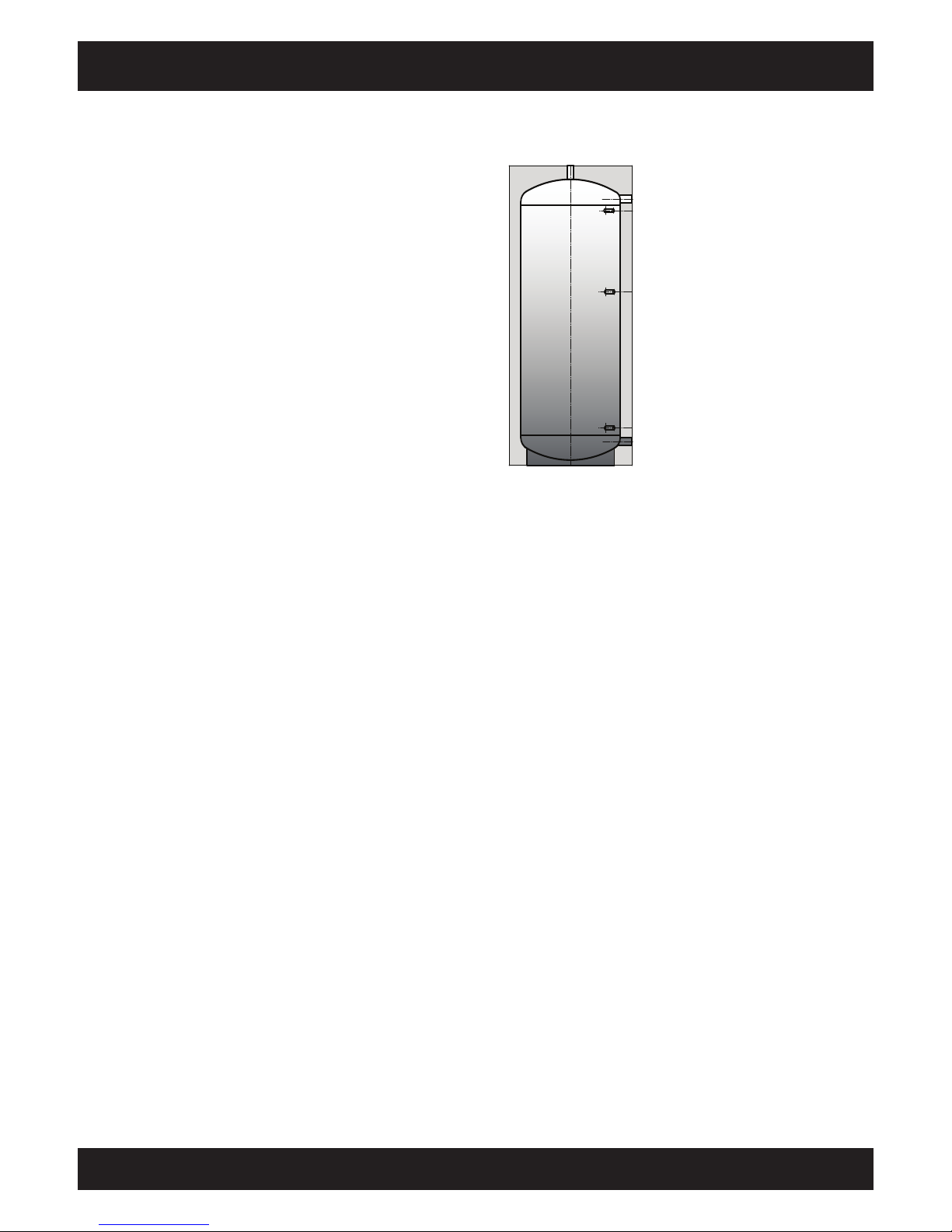
Flow from boiler
to the hot water tank
"Buffer bottom" temperature
sensor just above connection
Return to boiler
The boiler controls its output based
on the reading from the "Buffer
middle" temperature sensor. Enough
to provide sufficient heat to start a
consumer. Not too much to ensure
that the buffer is still able to store
heat after the heating circuits have
been switched off.
"Buffer top" temperature sensor just
under the connection
No external timer thermostats
The factory-standard controls include weekly
timers for two heating circuits.
If the heating pumps are controlled by the boiler
control, heat can be drawn from the boiler during
periods when the temperature setting has been
lowered as long as there is wood in the boiler.
This is especially important if you accidentally
put too much wood on in the evening, or if you
intentionally heat up the boiler to its full extent in
anticipation of a cold night.
Timer thermostats will switch off the heating
pumps punctually at the preset time, even if
wood is still burning in the boiler, and even if the
(undersized) buffer is incapable of storing more
heat. The only solution for the boiler is to stop its
air intake. Although this puts the fire out without
overheating the boiler, the wood will continue to
emit gas and the unburned wood gas resulting
from the lack of air will create tar deposits in the
boiler and flue.
A minimum power level is necessary to achieve
clean and complete combustion
The smaller the fire in the boiler, the lower the
temperature will be in the combustion chamber.
At about a third to a quarter of the full load, the
combustion temperature drops below 700°C and
the tar components in the wood gas no longer
burn completely. This drastically reduces the
efficiency (it can drop to below 50%), causes tar
build-up in the boiler's heat exchanger and in the
chimney and also results in unacceptable pollution
due to unburned hydrocarbons.
To maintain a clean-burning wood fire with
maximum fuel efficiency, a minimum power level
must be maintained and the best way to achieve
this is to use a buffer storage tank.
Why a buffer storage tank?
Many old log boilers that do not have buffer
storage tanks are still in use, so why do we need
them with today's wood-burning systems? The
answer to this frequently asked question is as
follows: In the days before heating control systems,
the boiler used the thermal mass of the entire
house as a buffer. If the boiler is replaced, and the
radiators are fitted with new thermostat valves
and/or a weather-dependent mixing system, the
log boiler is operated at too low an output level in
autumn and spring when the heating requirements
are minimal. At low output levels, the temperature
in the combustion chamber drops, but production
of wood gas doesn't. Hard-to-burn components
of the wood gas, such as tar or acetic acid no
longer combust; instead, they condense (create tar
deposits) either in the boiler's heat exchanger or
in the flue. The materials that are not deposited
pollute the environment.
A buffer storage tank is necessary to control this
low-load operation, which inevitably occurs with
a modern, energy-saving heating system. Heat
produced by the boiler for which there is no immediate use within the building is offloaded into a
buffer storage tank and retrieved by the heating
system as needed, for example, when the boiler is
not operating.
As a log wood boiler cannot simply be switched off
once it has been started up and while there is still
wood burning in it, it should be possible to store in
the buffer the energy content of the wood that is
still in the combustion chamber.
Page 18
18
www.eta.co.at
Hydraulic integration Buffer
M
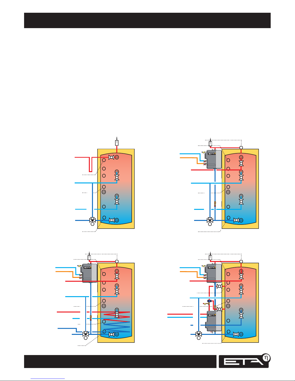
ETA stratified buffer SP
Upper buffer sensor
Middle buffer sensor
Lower buffer sensor
Log wood boiler flow
Heating circuits flow
Hot water tank flow
Oil/gas boiler flow
Log wood boiler return
Heating circuits return
Oil/gas boiler return
With conventional hot water supply
Start relief
ETA stratified buffer SP
Upper buffer sensor
Middle buffer sensor
Lower buffer sensor
Log wood boiler flow
Heating circuits flow
Oil/gas boiler flow
Log wood boiler return
Low-temperature circuits return
Oil/gas boiler return
With fresh water module
M
Start relief
Hot water tank return
Cold water
Hot water
Upper buffer sensor for hot water
ETA stratified buffer Solar SPS
With solar exchanger and fresh water module
ETA stratified buffer SP
Upper buffer sensor
Middle buffer sensor
Log wood boiler flow
Heating circuits flow
Oil/gas boiler flow
Oil/gas boiler return
With stratified charging module and fresh water module
M
Start relief
Cold water
Hot water
Upper buffer sensor for hot water
Upper buffer sensor
Middle buffer sensor
Log wood boiler flow
Heating circuits flow
Oil/gas boiler flow
Oil/gas boiler return
M
Start relief
Cold water
Hot water
Upper buffer sensor for hot water
High-temperature circuits return
Log wood boiler return
Low-temperature circuits return
High-temperature circuits return
Upper solar buffer sensor
Solar flow
Solar return
Solar flow
Solar return
Lower buffer sensor
+ lower solar buffer
Log wood boiler return
Low-temperature circuits return
High-temperature circuits return
Lower buffer sensor
Lower solar buffer sensor
For the largest possible buffer storage capacity and for
maximum solar yield even in winter, low return
temperatures are the goal.
The best stratified buffer can’t unmix what has been mixed
by heat distributors. Especially in houses where radiators
and underfloor circuits are present, no mixing heat
distributors should be installed, the returns should be
connected directly to the buffer. An underfloor heating
system can still be operated with the return from radiators.
If a solar heating system is connected, only the cold
returns from an underfloor heating system or from a fresh
water module may be fed into the solar-heated lower third
of the buffer. This results in lower solar panel working
temperatures with significantly higher efficiencies and also
significantly higher solar yield.
An oil or gas boiler should always be connected only
above the upper quarter of the buffer.
With a start relief the house will get warm faster when
the heating is switched on.
Siphon loops downward at all connections avoid heat
losses in summer.
Page 19
19
2012-11
Buffer Hydraulic integration of several buffers
SH Montage
Parallel or serial connection
between several buffers
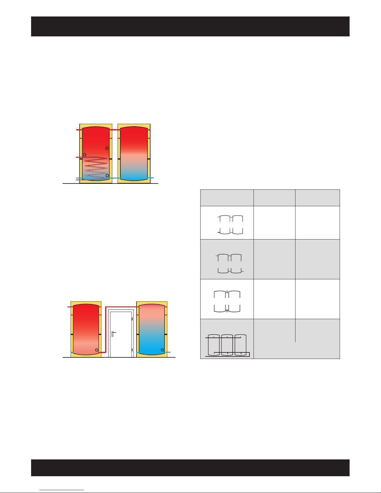
When there are several buffers, normally the parallel
connection (top with top and bottom with bottom)
is the better solution.
With a parallel connection, the entire buffer volume
is available to installed heat exchangers such as solar
heat exchangers or internal water heat exchangers
and suspended hot water tanks.
(Return)
Flow
Solar return
Return
Solar flow
If two buffer storage tanks of different dimensions
are connected in parallel, then the flow must be
connected to the higher one or the lower one must
be raised so that the upper connection can be
horizontal.
A serial connection between two buffers has no
advantages over a parallel connection; if anything
it is a disadvantage. For example, a suspended
hot water tank can get no heat from the second
buffer or an internal heat exchanger cannot heat
on both buffers. For this reason, with serial buffers
one should connect a solar supply using either
heat exchangers in both buffers or better with an
external heat exchanger.
Return
Flow
With rare exceptions, the use of the serial
connection (buffer 2 top and buffer 1 bottom
connected) is limited to overcoming spatial obstacles
in the given installation situation. Only a serial
connection is possible if the passage to a door
needs to be kept free or for large distances between
buffers.
Tichelmann connection for higher outputs
For parallel connection with one-sided connection,
the volume of the second buffer is integrated via
thermosiphon principle. The exchange between
the two tanks is driven only by gravity and limited
by the hydraulic resistance of the junctions, so
for medium outputs a Tichelmann connection is
required.
With a 6/4" connection, a maximum of 5,500 l/h
at 0.25 mH
2
O pressure loss is possible (for flow and
return connections together). This corresponds to
130 kW at a spread of 20°C. Therefore, for higher
outputs external piping, either symmetric or with
Tichelmann connection, is needed.
With more than two tanks, external piping with
Tichelmann connection is also needed to fill and
drain all tanks uniformly.
Parallel buffer storage
tanks
Buffer connections
5/4" DN32
Buffer connections
6/4"
DN40
one-sided connection
up to 25 kW
boiler output
up to 40 kW
boiler output
internal
Tichelmann connection
up to 80 kW
boiler output
up to 130 kW
boiler output
Symmetric connection
for more than
80 kW boiler output
for more than
130 kW boiler output
external piping with
Tichelmann connection
for more than
80 kW boiler output
for more than
130 kW boiler output
and/or
for more than two buffer storage tanks
Flow
Return
Flow
Return
Flow
Return
Maximum 2 buf fers
Maximum 2 buf fers
Flow
Return
Maximum 2 buf fers
Buffer storage tanks demand softened water
If buffer storage tanks are installed in a heating
system, the system must be filled with softened
water. Around 0.25 kg of limescale will precipitate
from a cubic metre of water with 15° of German
hardness.
Page 20
20
www.eta.co.at
Parallel buffers with internal Tichelmann Buffer
Cold water
Hot water
Solar
flow
Solar
return
M
M
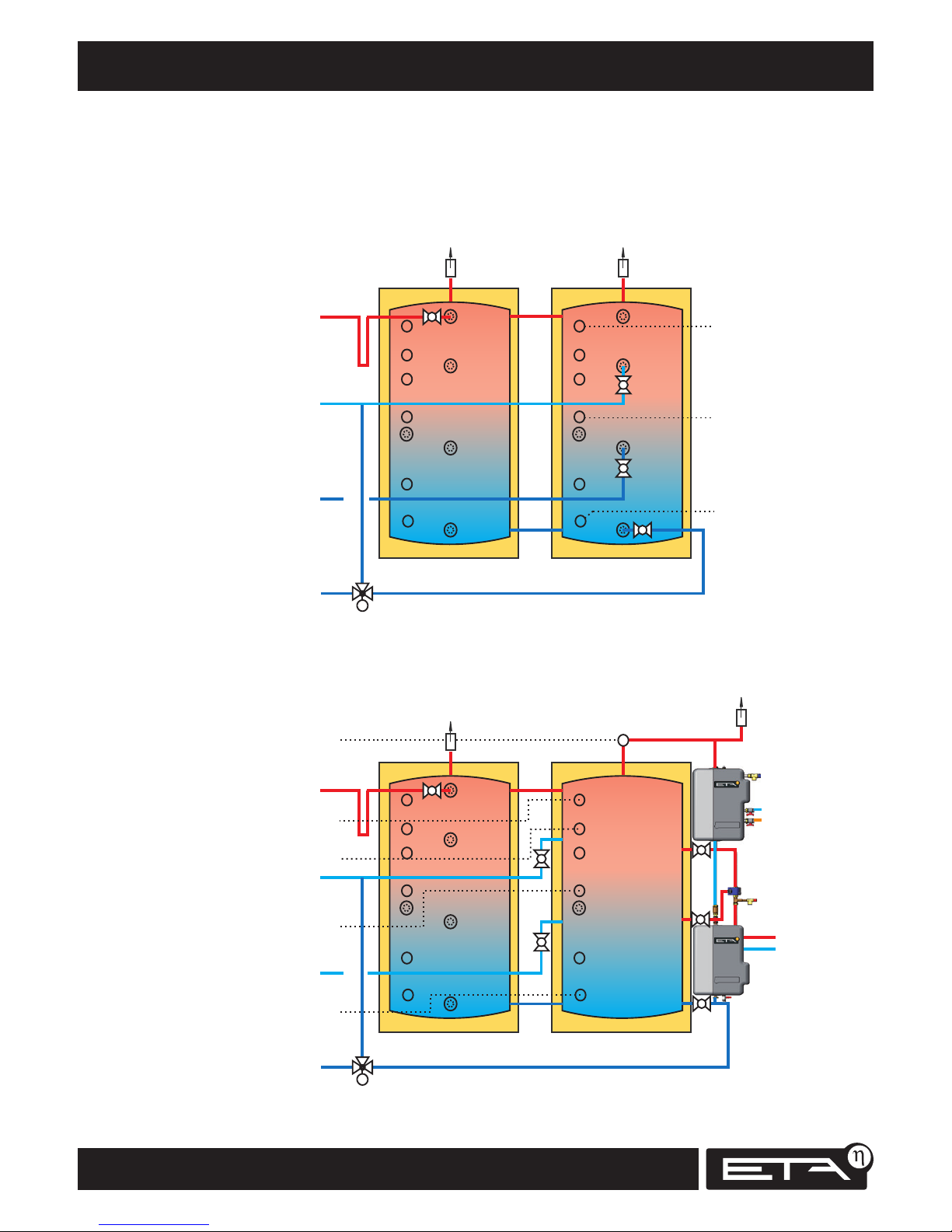
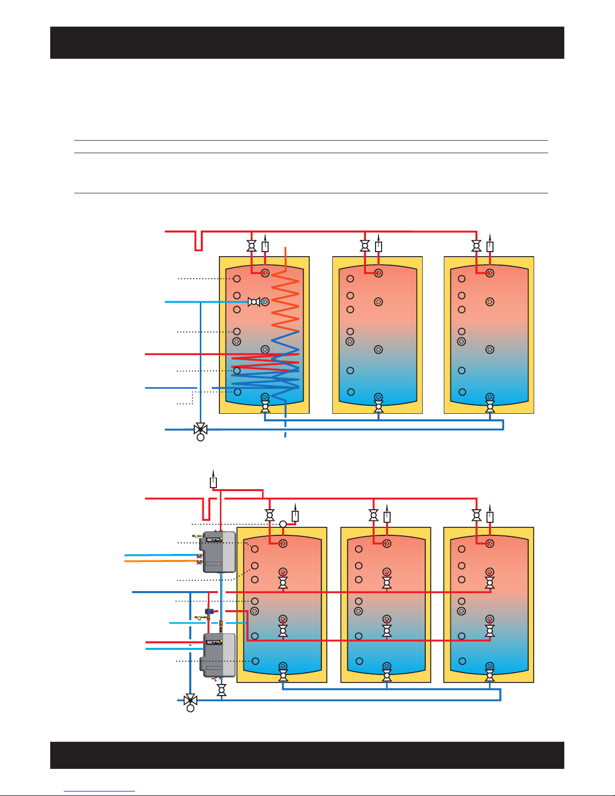
The basic principle of the internal Tichelmann is diagonal flow; two buffers are connected together at the top
and bottom (= parallel connection). For output up to 90 kW, a connection with DN32 (ETA buffer connection
set) is sufficient, for 30 kW at least R1” or 28 mm copper. On one tank, the boiler outlet is
connected at the top; on the other the boiler return is connected at the bottom.
DN32
DN32
ETA stratified buffer SP ETA stratified buffer SP
Upper buffer
sensor
Middle buffer
sensor
Lower buffer
sensor
Log wood boiler flow
Heating circuits flow
Hot water tank flow
Oil/gas boiler flow
Hot water tank return
High-temperature circuits
return
Log wood boiler return
Low-temperature circuits
return
Oil/gas boiler return
For a sufficiently large hot water reserve,
the enabling temperature should be over 45°C!!
Return lines with strongly differing temperatures
should be fed into the buffer storage tank separately
To minimise pipe circulation losses it is helpful to make the connections with downward siphon loops.
DN32
DN32
ETA stratified buffer SP ETA stratified buffer SP
Upper buffer sensor
Middle buffer sensor
Lower buffer sensor
+ lower solar buffer
Log wood boiler flow
Heating circuits flow
Oil/gas boiler flow
High-temperature circuits
return
Log wood boiler return
Low-temperature circuits
return
Oil/gas boiler return
Return lines with strongly differing temperatures
should be fed into the buffer storage tank separately
Two parallel buffers and conventional hot water supply
Two parallel buffers with fresh water module and solar stratified charging
Start reliefStart relief
Buffer top solar
Upper buffer sensor for hot water
Page 21
21
2012-11
Buffer Parallel buffers with external Tichelmann
SH Montage
M
M
High-temperature circuits return
Stratified buffer with/without internal
water heat exchanger
Start relief
ETA stratified buffer SP
ETA stratified buffer SP
ETA stratified buffer SP
ETA stratified buffer SP
ETA stratified buffer SP
Log wood boiler return
Low-temperature circuits
return
Upper buffer sensor
Middle buffer sensor
Lower buffer sensor
+ buffer bottom solar
Upper buffer sensor for hot water
Upper solar buffer sensor
Total output up to
Shut-off valves on buffer
Collector line at least
30 kW
DN 20
DN25
R 1“- 28x1,5
300 kW
DN 40
DN65
R 2½“- 76x2
160 kW
DN 32
DN50
R 2“- 54x1,5
90 kW
DN 32
DN40
R 1½“- 42x1,5
60 kW
DN 25
DN32
R 1¼“- 35x1,5
450 kW
DN 40
DN80
R 3“- 89x2
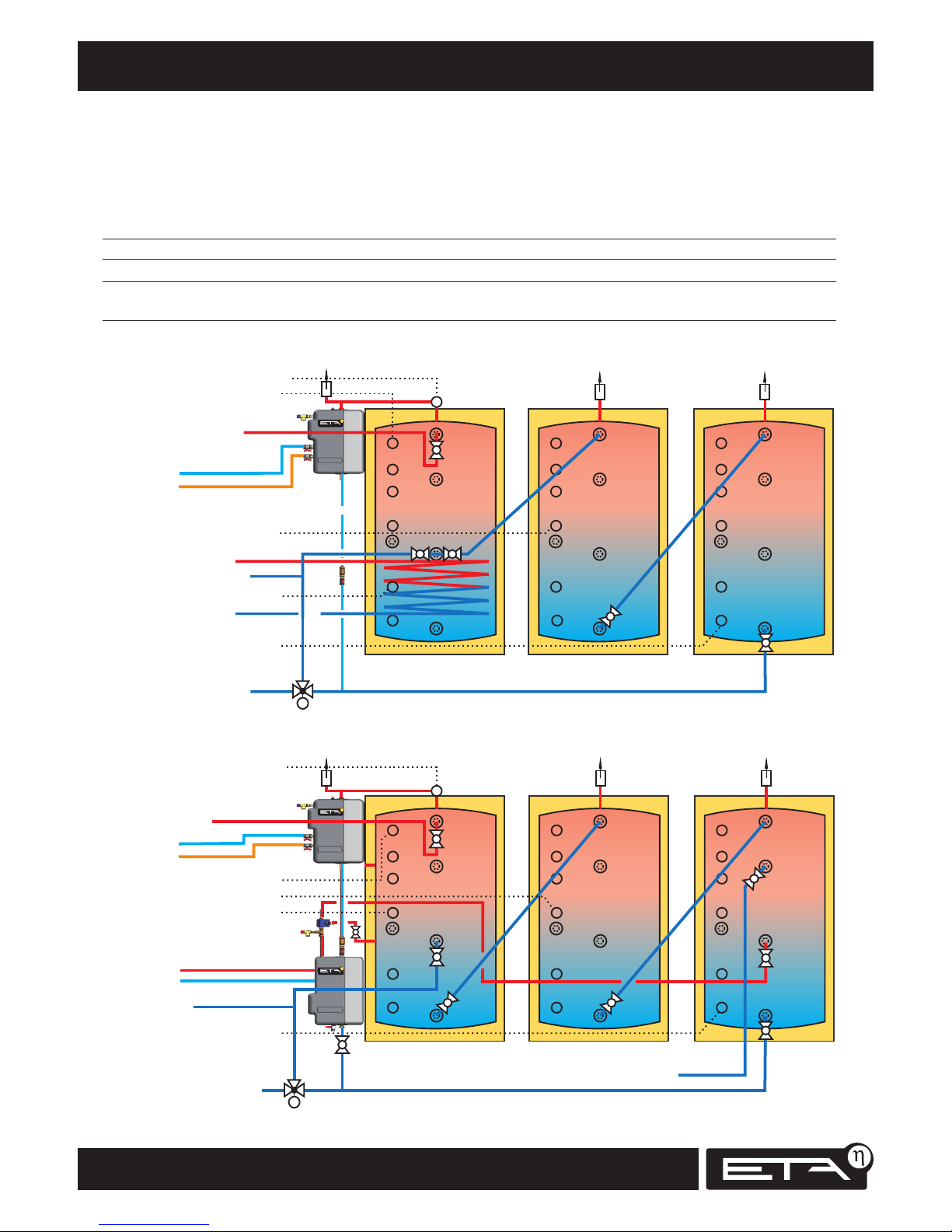
To minimise pipe circulation losses it is helpful to incorporate siphon loops downward in the connection lines.
Three or more parallel buffers with hot water tank or internal water heat exchanger
Three or more parallel buffers with fresh water module and solar stratified charging
Log wood boiler flow
Heating circuits flow
Hot water tank flow
Oil/gas boiler flow
Log wood boiler return
Heating circuits return
Hot water tank return
Oil/gas boiler return
Upper buffer sensor
Middle buffer sensor
Lower buffer sensor
Log wood boiler flow
Heating circuits flow
Oil/gas boiler flow
Cold water
Hot water
Solar flow
Solar return
Oil/gas boiler return
Cold water
Hot water
Lower boiler sensor solar
Solar flow
Solar return
For a small solar heating system, individual buffers can be
shut down in the summer to reduce the total volume.
The basic principle of the external Tichelmann is parallel flow through several buffer storage tanks, which is achieved
with diagonally alternating connection of the collectors. The last buffer on the flow collector is the first on the return
collector. To achieve uniform charging/discharging, the stub lines should be minimum one or two sizes smaller than
the collector. There is no output limit for this circuit.
Page 22
22
www.eta.co.at
Serial buffers Buffer
M
Solar flow
Solar return
M
High-temperature circuits return
Start relief
ETA stratified buffer SP
Log wood boiler return
Low-temperature circuits
return
Upper buffer sensor
Middle buffer sensor
Lower buffer sensor
+ lower solar buffer
Upper buffer sensor for hot water
Upper solar buffer sensor
Total output up to
Number of buffer storage tanks
Connection line at least
30 kW
4
DN25
R1“- 28x1,5
140 kW
4
DN50
R2“- 54x1,5
100 kW
2
DN40
R1½“- 42x1,5
80 kW
4
DN40
R1½“- 42x1,5
50 kW
4
DN32
R1¼“- 35x1,5
170 kW
2
DN50
R2“- 54x1,5
To minimise pipe circulation losses it is helpful to incorporate siphon loops downward in the connection lines.
Serial connection and conventional hot water tank or fresh water module
Serially connected buffers with fresh water module and solar stratified charging
Log wood boiler flow
Heating circuits flow
Oil/gas boiler flow
Log wood boiler return
Heating circuits return
Hot water tank return
Oil/gas boiler return
Upper buffer sensor
Middle buffer sensor
Lower buffer sensor
Log wood boiler flow
Heating circuits flow
Oil/gas boiler flow
Cold water
Hot water
Solar flow
Solar return
Oil/gas boiler return
65 kW
2
DN32
R1¼“- 35x1,5
ETA stratified buffer SP ETA stratified buffer SP
ETA stratified buffer SPETA stratified buffer Solar SPS ETA stratified buffer SP
High-temperature circuits return
Cold water
Hot water
Lower boiler sensor solar
Upper buffer sensor for hot water
If there are different buffer types, or if not all buffers can be set up in one group, serial connection of the buffers
is necessary. Note that for serial buffer connection, integration of a solar heating system only works satisfactorily
if a fresh water module is used for the hot water. Solar tanks with internal solar exchangers are only of limited
effectiveness. Combination tanks with suspended hot water tanks or internal water heat exchangers are unsuitable
for a serial buffer connection.
Page 23

23
2012-11
Buffer Serial buffers
SH Montage
Page 24
24
www.eta.co.at
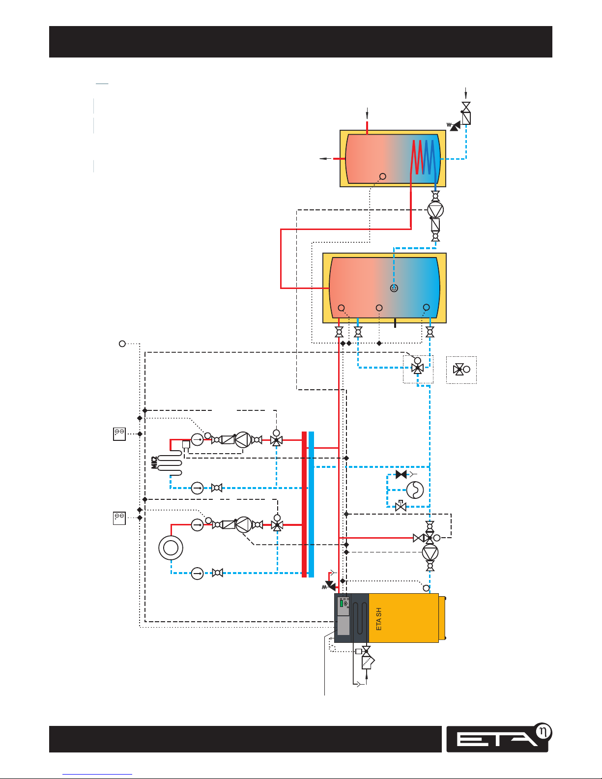
Hydraulic schematic
Datum:
25.01.2006
Re v.:
00
Kesseltyp:
ETA SH Stückholzkessel
Konfiguration:
Puffer + Boiler
M
T buffer top
T buffer middle
Buffer pump
T buffer bottom
Outside temperatureRoom 2
T boiler
Mixing valve 2
Pump 2
T flow 2 (Pos. 7)
MK2
M
Mixing valve 1
Pump 1
T flow 1
M
MC1
T
Room 1
Return temp.
Heating temp. limiter
Buffer
Hot water tank
Return riser
Start relief
Hot water tank pump
M
A
B
AB
M
AB
B
A
3-way valve
3-way mixing valve
T
Cold water
Heating circuit control
for 2 mixing circuits
for installation in the
boiler: SH1-0
4x1² 4x1²
4x1²
3x1²
2x0,5²
3x1²
3x1²
3x1²
2x0,5²
4x0,5² 4x0,5² 2x0,5²
Cold water
2x0,5²
4x1²
2x0,5²
2x0,5²
2x0,5²
2x0,5²
19010
THW
THWC
Page 25

25
2012-11
Hydraulic schematic
SH Montage
Datum:
15.03.2011
Re v.:
03
Kesseltyp:
ETA SH Stückholzkessel
Konfiguration:
Puffer +Brenner
M
Buffer pump
Room 2
Mixing valve 2
Pump 2
T flow 2
MC2
M
Mixing valve 1
Pump 1
T flow 1
M
MC1
Room 1
Return temp.
Heating
temp.
limiter
Return riser
T
Cold water
A
B
AB
3-way valve
AB
B
A
3-way mixing valve
Start relief
2x0,5²
T outside
ETA stratified
charging module
2x0,5²
T Collector
2x0,5²
Wall housing for ETA FWM + SLM
for standard control system
Oil/gas boiler
Auxiliary boiler pump
Tres
2x0,5²
3x1²
3x1²
CW
HW
M
DN32
DN32
ETA stratified buffer SP ETA stratified buffer SP
M
2x0,5²
T buffer bottom
T buffer middle
T buffer top
2x0,5²
2x0,5²
Solar buffer bottom²
2x0,5²
Solar buffer top
2x0,5²
T buffer top HW
ETA fresh
water module
4x1²
4x1²
4x1²
3x1²
2x0,5²
3x1²
3x1²
2x0,5²
2x0,5²
4x0,5² 4x0,5²
4x1²
Twisted Pair 2x2x0,6²
CAN bus (L = max. 400m)
Set the enabling temperature for
the heating circuits high enough so
that enough heat remains in buffer
for the fresh water module.
3x1²
Page 26
26
www.eta.co.at
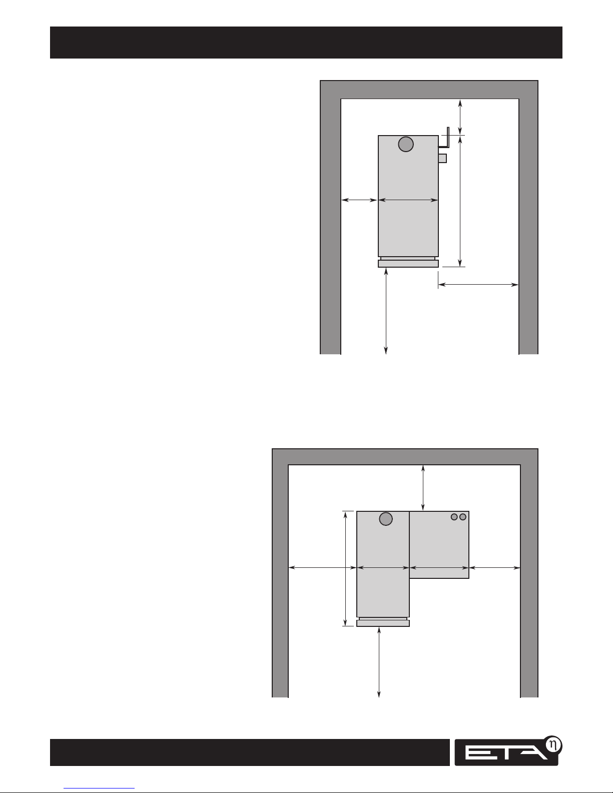
> 300 mm
610 (710) mm
> 800 mm
>200 mm
1100 (1174) mm
> 800 mm
SH 20-60 kW
> 500 mm
610 mm
> 400 mm > 100 mm
686 mm
1100 mm
> 800 mm
SH-P
20 - 30 kW
TWIN 20/26
Minimum clearances for maintenance Installation
Minimum clearances for maintenance for SH
The adjacent sketch shows the space requirements
and clearances for maintenance and installation of
the boiler.
Will an SH-P boiler be installed
for a TWIN burner?
If a TWIN auxiliary boiler for pellets might
be installed later, the additional space it
will need must be taken into account when
setting up the SH boiler.
Mirror image for TWIN to the left
The dimensions in parentheses apply for 40, 50
and 60 kW boilers.
On one side, left or right, the boiler needs 800 mm
of clearance for maintenance, so it can also be set
up in a mirror image of the sketch.
The sketch shows a boiler with right-hand
pellet burner; for a left-hand pellet burner
a mirror image applies.
Page 27
27
2012-11
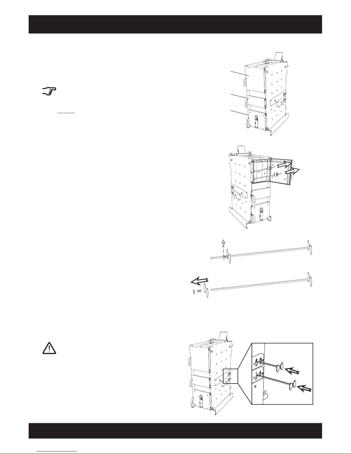
Installation Air valves for log boilers
SH Montage
Installing air valves on an
SH boiler without TWIN burner
Installation of the air valves for an SH boiler
without an additional flange for a TWIN burner is
described here.
The air valves for an SH boiler with a pellet
flange for the TWIN burner (SH 20P, SH 30P)
are different; their installation is described on
page 29.
Fuel chamber door
SH 20 - 60 kW boiler
Ignition door
Combustion chamber
door
Prepare shafts for air valves
Pull the cotter pin on the spring side. Then remove
the washer, the spring and an air valve from the
shafts for primary and secondary air.
Push shafts into boiler
Push both shafts into the air boxes from the side
on which the actuators will not be mounted.
Take both air valves from fuel chamber
Take both shafts, including air valves, from the fuel
chamber.
Page 28
28
www.eta.co.at
Minimum clearances for maintenance Installation
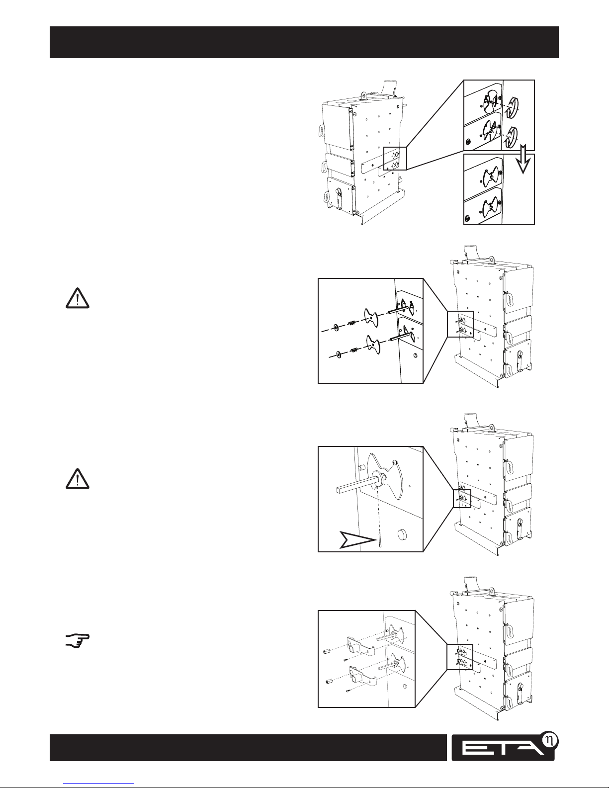
Position air valves
Turn both air valves to the closed position.
Replace air valves
Push the air valves, springs and washers onto the
air valve shafts.
Both air valves must be installed in the closed
position on both sides.
Install cotter pins on air valve shafts
Install cotter pins on the air valve shafts so that the
air valves are pressed against the air boxes by the
springs.
The air valves must be completely flush with the air
boxes on both sides of the boiler.
Install actuator brackets
Attach the brackets for the actuators to both air
valves. Fasten each bracket with an M8 long nut
and a self-tapping screw.
Turn both air valve shafts and check their smooth-
ness of movement.
Page 29
29
2012-11
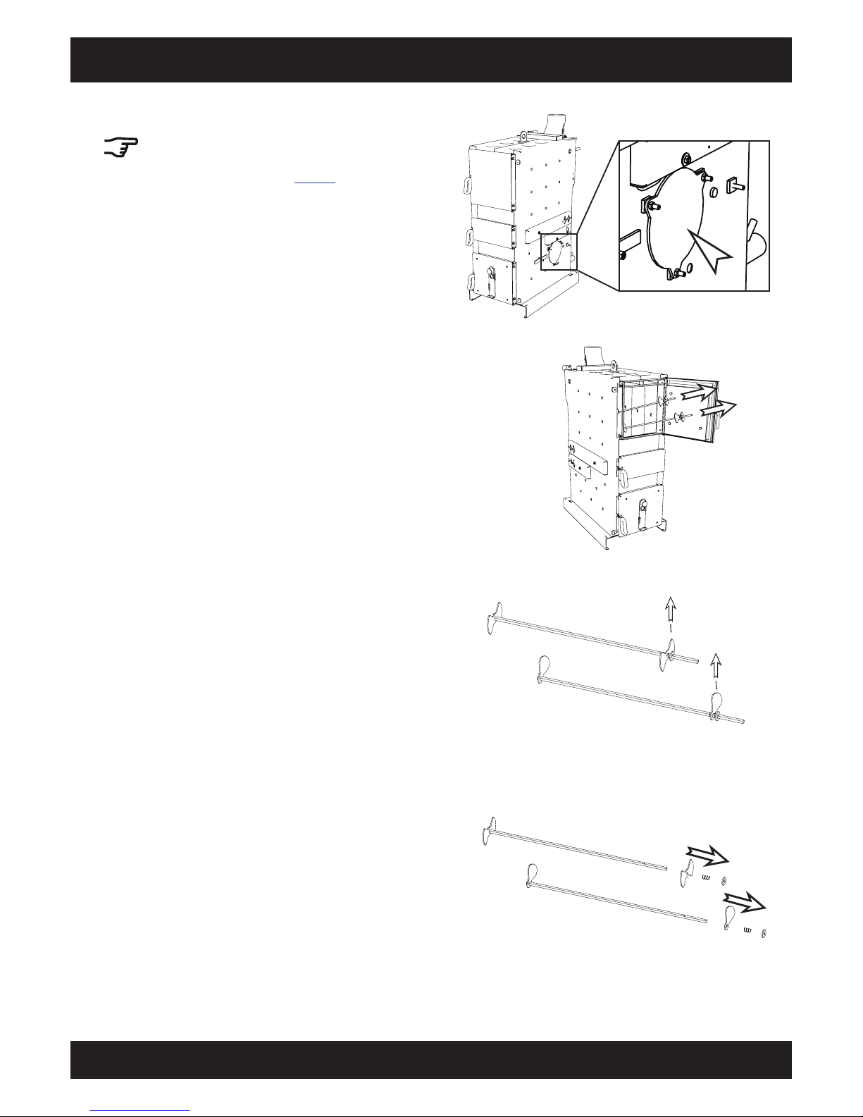
Installation Air valves for log boilers with pellet flange
SH Montage
Air valves for log boilers with pellet flange
The air valves for a log boiler with pellet flange
for the TWIN burner are different; for boilers
without a burner flange, see page 27.
Prepare air valve shafts
for primary and secondary air
Pull the cotter pin on the spring side.
Remove the washer, the spring and an air valve
from both shafts.
Take both air valves from fuel chamber
Take both shafts, including air valves, from the fuel
chamber.
Page 30
30
www.eta.co.at
Air valves for log boilers with pellet flange Installation
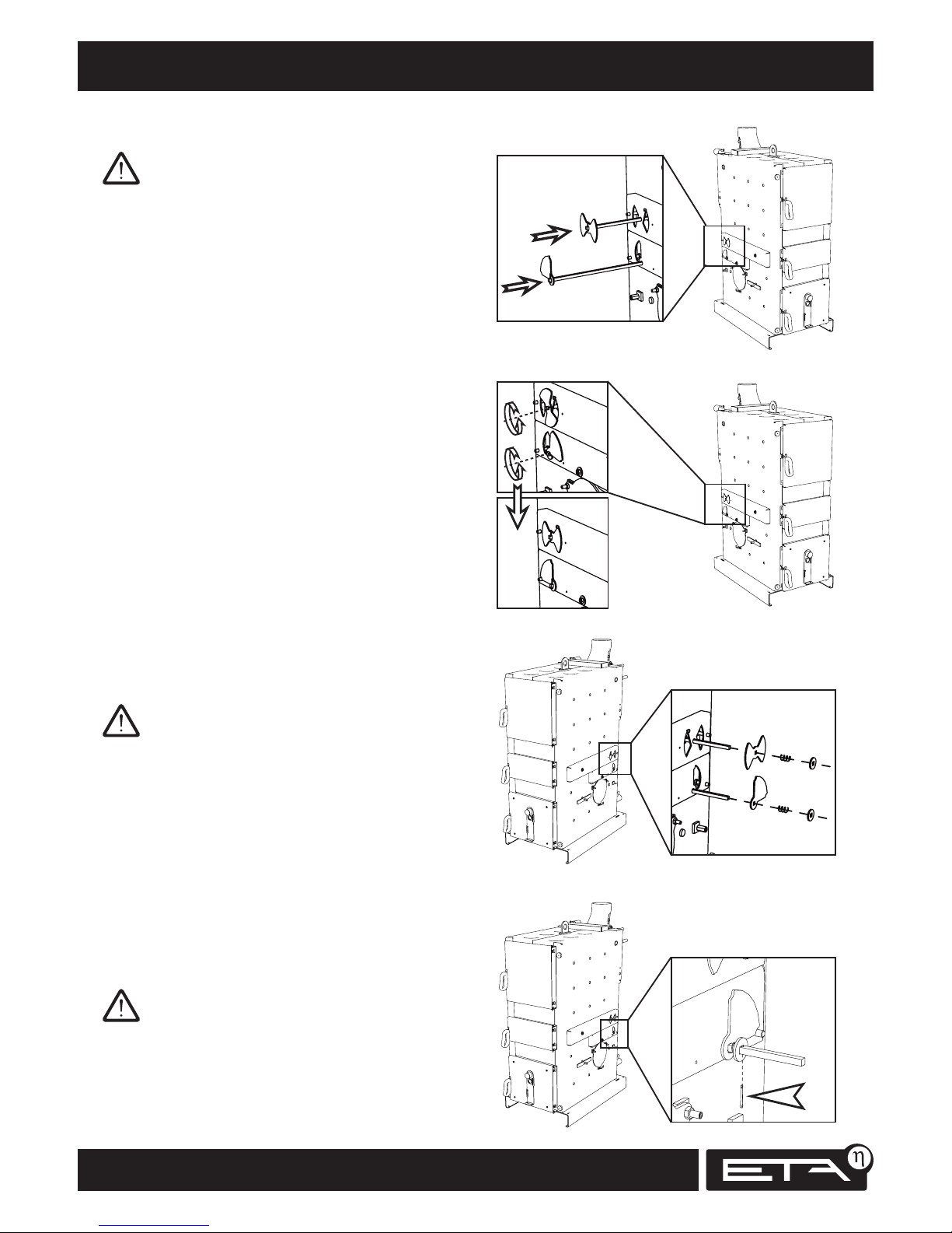
Position air valves
Turn both air valves to the closed position.
Replace air valves
Push the air valves, springs and washers onto the
air valve shafts.
Both air valves must be installed in the closed
position on both sides.
Install cotter pins on air valve shafts
Install cotter pins on the air valve shafts so that the
air valves are pressed against the air boxes by the
springs.
The air valves must be completely flush with the air
boxes on both sides of the boiler.
Push air valve shafts into boiler
Push both air valve shafts into the air boxes from
the side on which the TWIN will be installed later.
Page 31
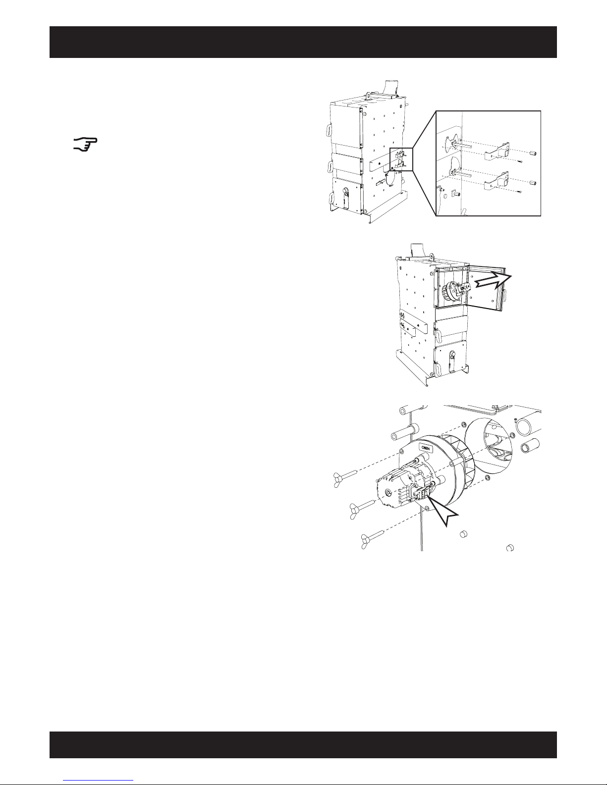
31
2012-11
Installation Draught fan
SH Montage
Install actuator brackets
Attach the brackets for the actuators to both air
valves. Fasten each bracket with an M8 long nut
and a self-tapping screw.
Turn both air valve shafts and check their smooth-
ness of movement.
Install draught fan
Attach the draught fan to the rear side of the boiler
with 3 M8 x 60 wing screws.
The draught fan's electrical connector must be on
the right when viewed looking towards the boiler.
Take draught fan from fuel chamber
Take the draught fan out of the fuel chamber.
Page 32
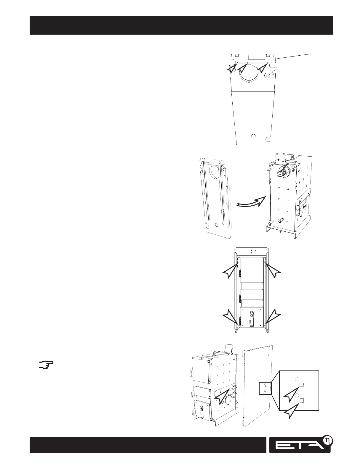
32
www.eta.co.at
Rear wall insulation, door frame Installation
Attach angle bracket to rear wall insulation
Fasten the angle bracket to the rear wall insulation
with 3 self-tapping 3.5 x 9.5 screws.
Attach rear wall insulation to boiler
Press the rear wall insulation onto the rear side of
the boiler.
Break out openings for air valve shafts from side
panel
Take the side panel for the side on which the actu-
ators are to be mounted.
Use a screwdriver to break out both openings for
the air valve shafts from this side panel.
Angle bracket
Install door frame
Attach the door frame to the front of the boiler
with 4 M5 X 10 round-headed screws.
Page 33
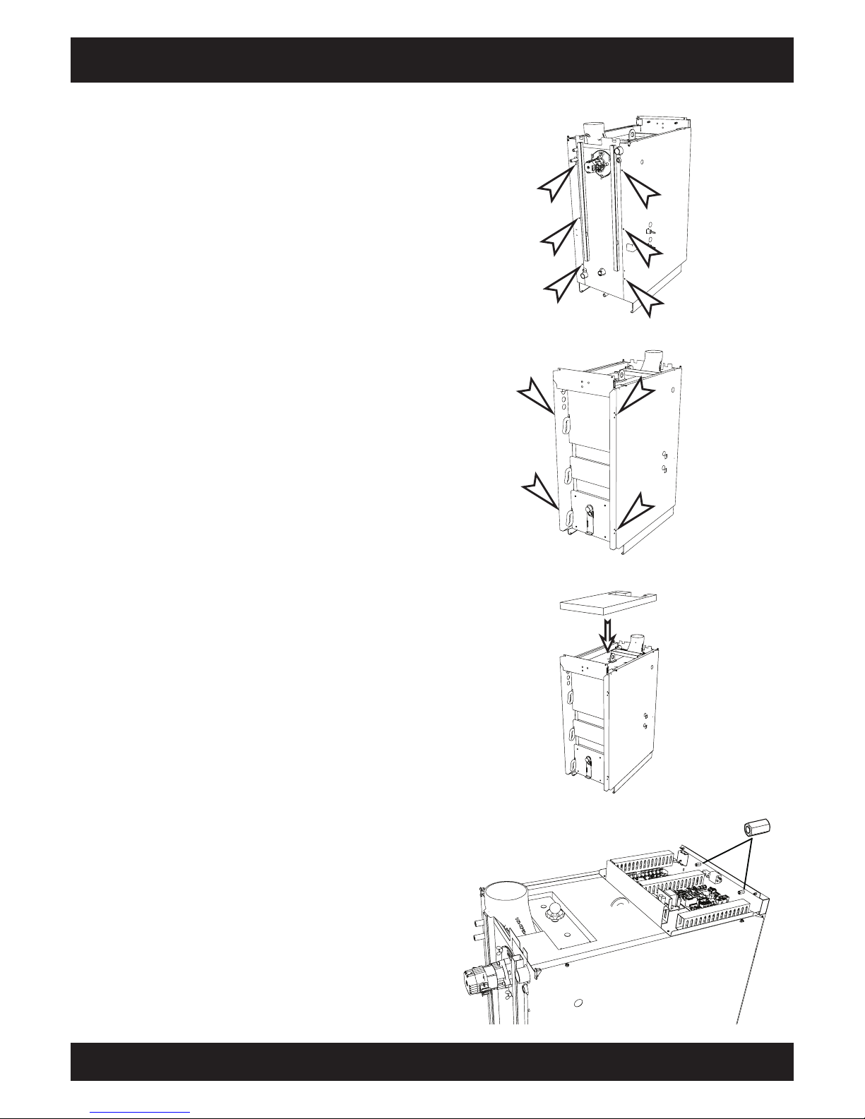
33
2012-11
Installation Side panels, boiler control system
SH Montage
Place insulation on top of boiler
Place the largest piece of insulation in the middle
of the boiler's top side.
Attach boiler control system to door frame
Loosen both M8 long nuts on the inner side of the
door frame. Place the boiler control system on the
boiler and remove the cable ties. Fasten the boiler
control system to the door frame with the long
nuts.
Install left and right side panels
Attach the side panels to the rear side of the boiler
with 6 M5 X 10 round-headed screws.
Attach the side panels to the front side of the boiler
with 4 M5 X 10 round-headed screws.
Page 34
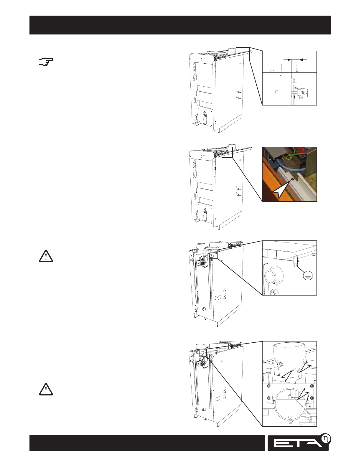
34
www.eta.co.at
> 5 cm
Cable duct, flue gas temperature sensor Installation
Change length of cable ducts
The cable ducts for the left and right sides of the
boiler are different due to the openings.
Put both cable ducts on the boiler and fit their
lengths to the boiler room. The cable ducts should
extend at least 5 cm over the rear wall of the
boiler; ideally they should extend to the wall
behind the boiler.
Connect control system's earthing wire
Run the earthing wire from the control system to
the rear side of the boiler and screw it onto the
side wall.
Install flue gas temperature sensor
Run the wire for the flue gas temperature sensor
(striped silver-black) to the flue outlet. Insert the
temperature sensor into the coupling on the flue
outlet and secure it with the screw.
Let it project in far enough so that the screw clamps
the sensor's metal sleeve and not the wire.
Fasten cable ducts
Fasten the left and right cable ducts with one 3.5
x 9.5 self-tapping screw each.
Page 35
35
2012-11
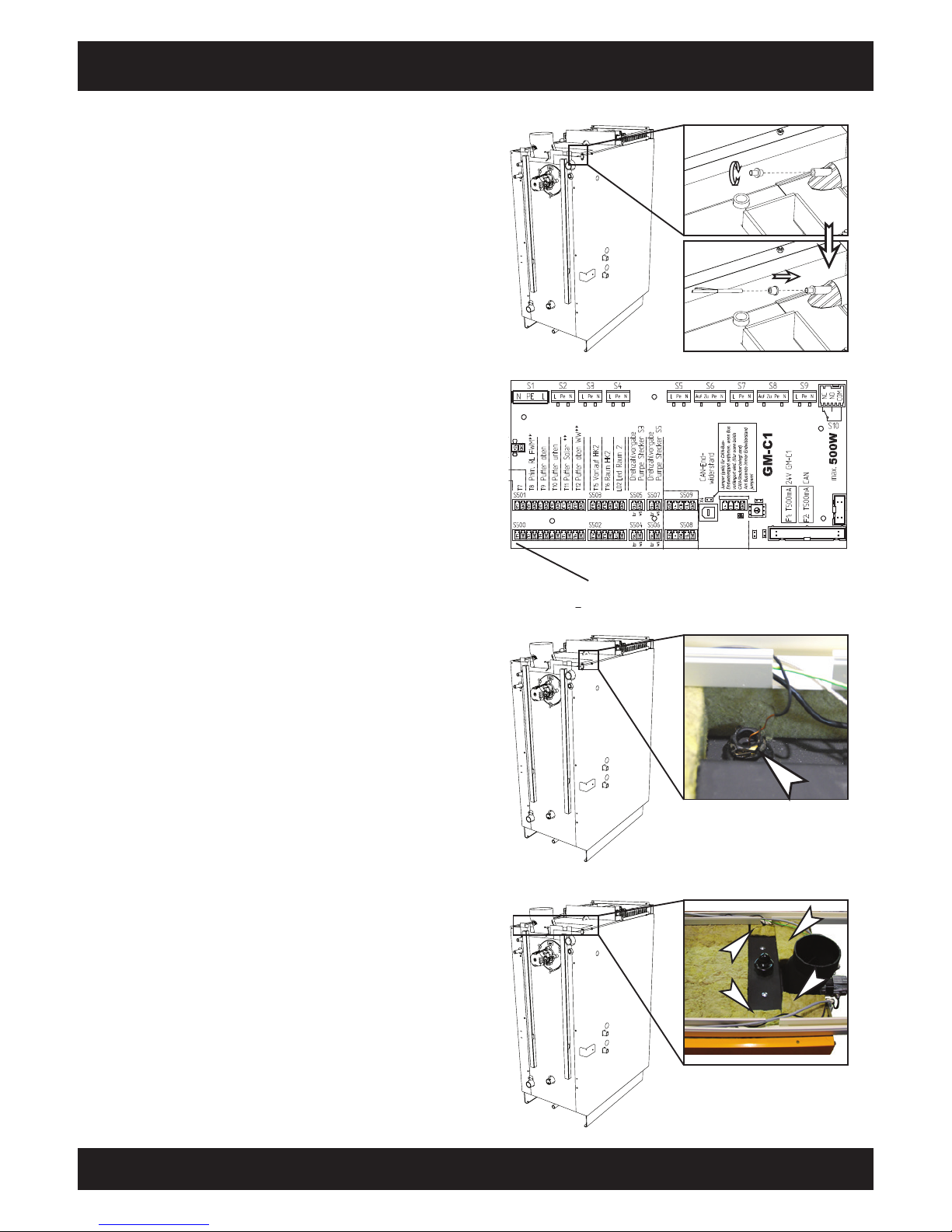
S500 / T1
Installation Temperature sensor - flow
SH Montage
Install temperature sensor on flow
Run the cable for the temperature sensor through
the cable ducts to the flow connection on the rear
side of the boiler.
Screw the front part of the clamp into the immersion sleeve.
Place the cap on the temperature sensor and insert
the sensor into the immersion sleeve as far as it
will go. Then push the cap forward and screw it
onto the clamp.
Install temperature sensor on boiler body
Insert the temperature sensor for the safety
temperature limiter (copper wire with black insulation) into the immersion sleeve next to the heat
exchanger cover on the top of the boiler.
Push the sensor into the immersion sleeve as far as
it will go, then attach the retaining spring.
Connect cable for flow temperature sensor
Connect the cable to the GM-C circuit board at the
S500 / T1 terminal.
Place insulation on top of boiler
Place the remaining pieces of insulation on top of
the boiler.
Page 36
36
www.eta.co.at
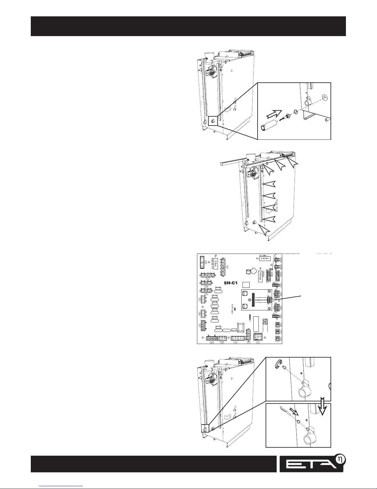
S570
Lambda probe, temperature sensor - return Installation
Connect lambda probe cable
Connect the cable to the SH-C circuit board at the
S570 terminal.
Install lambda probe cable
Run the lambda probe's cable along the rear of the
boiler in the right cable duct to the circuit board.
Install temperature sensor on return
Run the cable for the temperature sensor through
the cable ducts to the return connection on the
rear side of the boiler.
Screw the front part of the clamp into the immersion sleeve.
Place the cap on the temperature sensor and insert
the sensor into the immersion sleeve as far as it
will go. Then push the cap forward and screw it
onto the clamp.
Install lambda probe
Unscrew the retaining tube on the rear side of
the boiler and insert the lambda probe into the
retaining tube.
Together with the copper washer and the retaining
tube, screw the lambda probe into the boiler.
Use a pipe wrench to tighten the lambda probe's
retaining tube securely.
Page 37
37
2012-11
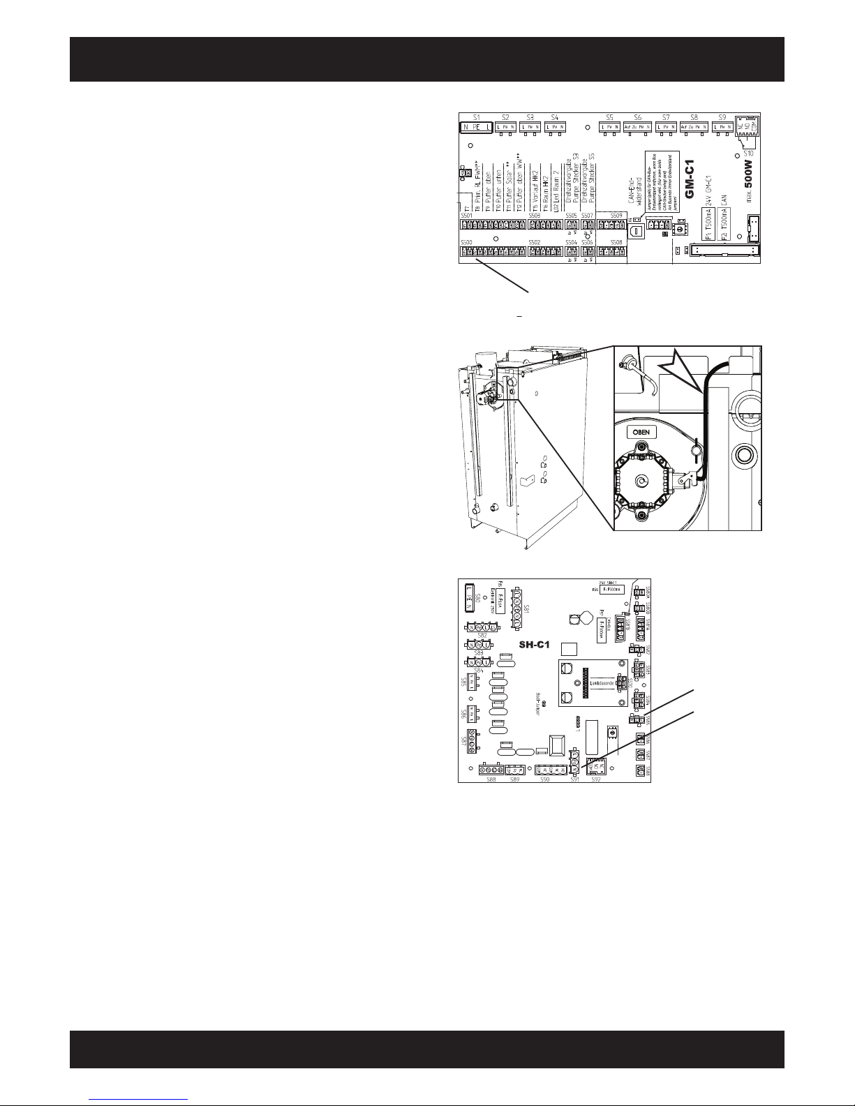
S500 / T2
S585
S91
Installation Connecting draught fan
SH Montage
Connect cable for return temperature sensor
Connect the cable to the GM-C circuit board at the
S500 / T2 terminal.
Install draught fan cable
Run the draught fan's cable on the rear side of the
boiler next to the cable duct.
Connect draught fan cable
Connect the cable to the SH-C circuit board at the
S91 and S585 terminals.
Page 38
38
www.eta.co.at
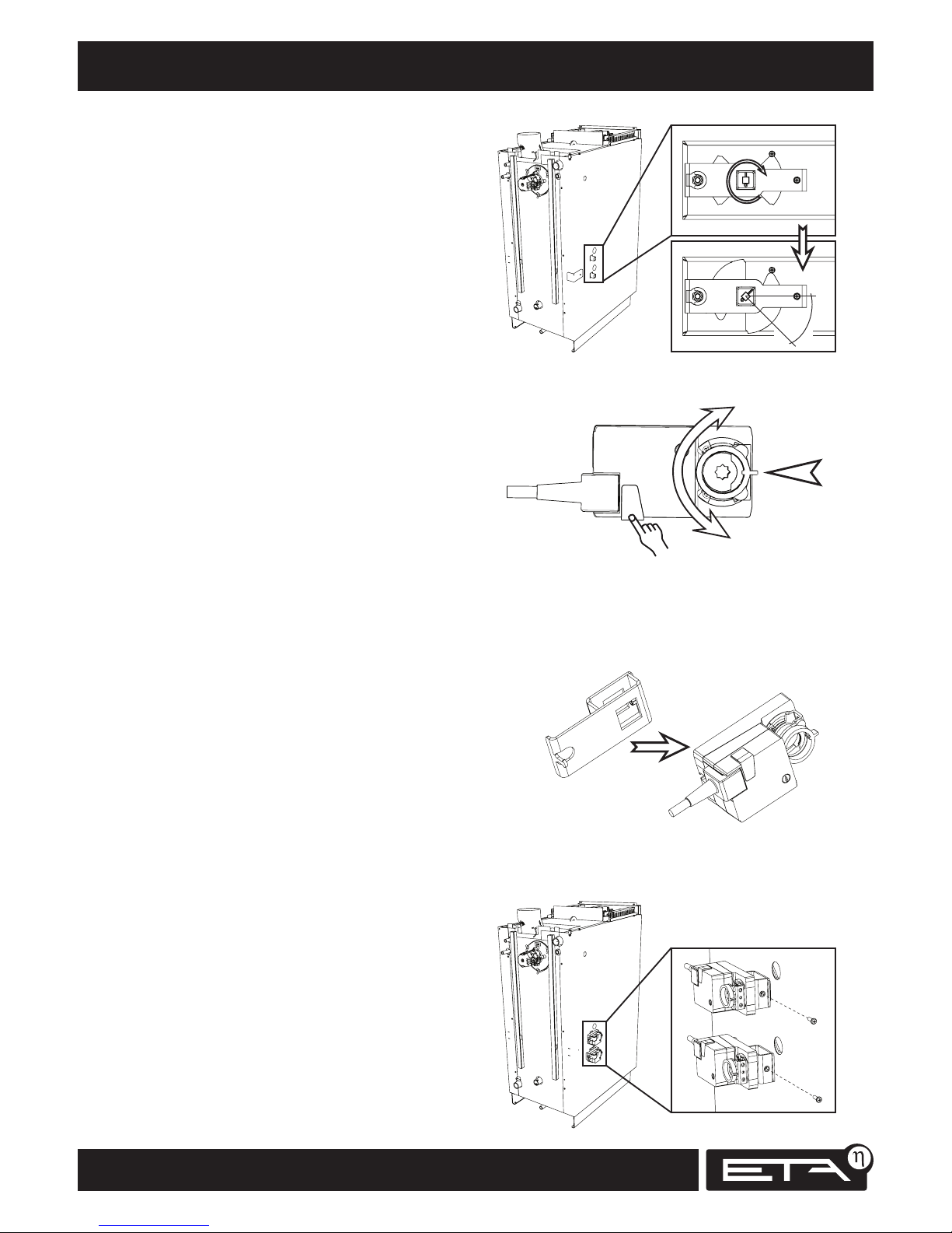
45°
Actuators Installation
Turn air valve shafts to 45° position
Turn both air valve shafts to the 45° position.
Turn actuator to middle position
Press the button on the actuator to turn the
actuator by hand.
Turn the actuator to the middle position so that the
recess is centred.
Attach brackets to actuators
Fit the brackets to the rear sides of both actuators.
Attach actuators
Press the actuators with the brackets onto both air
valve shafts. Tighten the screws on the brackets.
Page 39
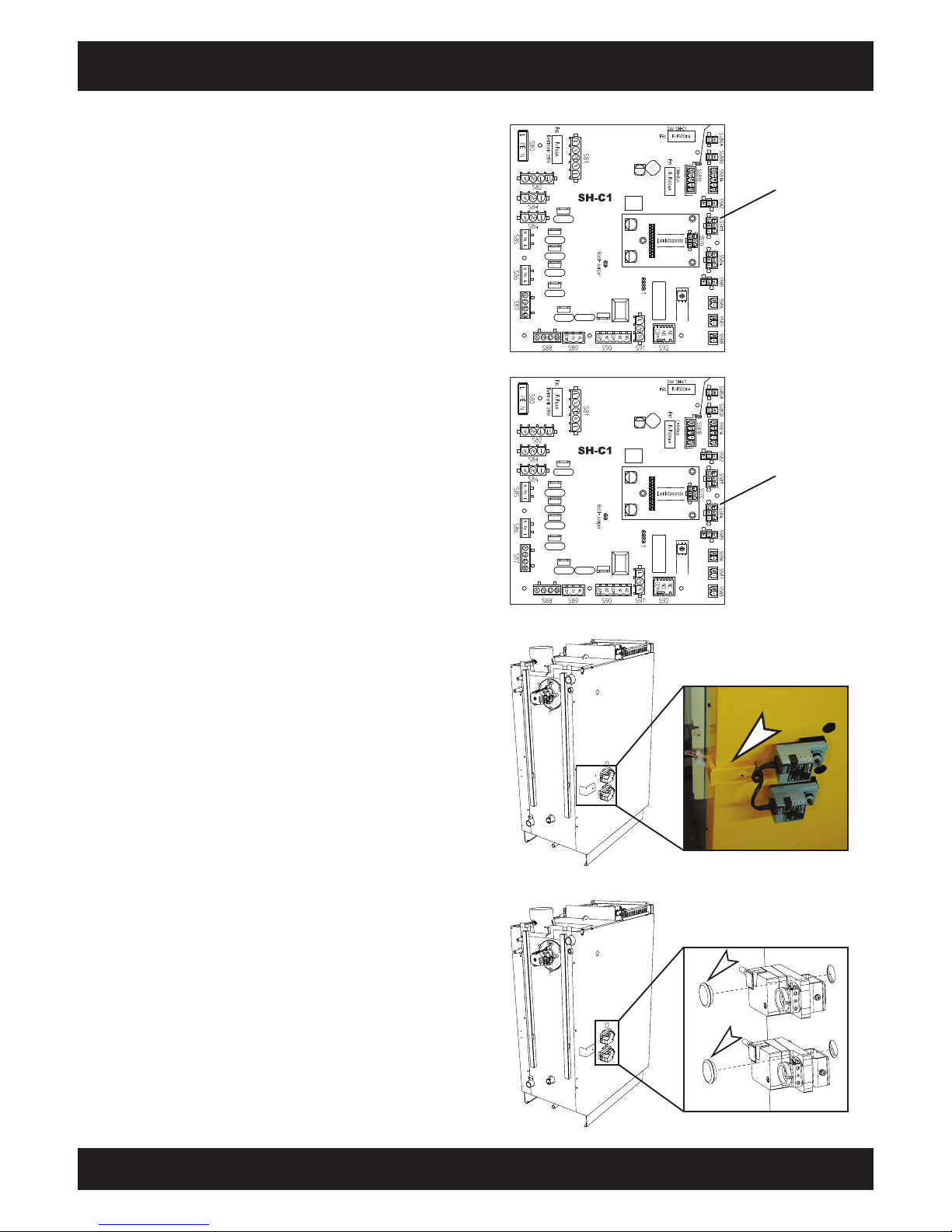
39
2012-11
S583
S584
Installation Actuators
SH Montage
Connect cable to upper actuator
Connect the cable to the upper actuator and run it
through the cable ducts to the circuit board.
Connect the cable to the SH-C circuit board at the
S583 terminal.
Connect cable to lower actuator
Connect the cable to the lower actuator and run it
through the cable ducts to the circuit board.
Connect the cable to the SH-C circuit board at the
S584 terminal.
Insert rubber caps
Insert two rubber caps into the openings on the
left and right side panels.
Attach cable cover
Run the actuator cables under the cover. Screw the
cover onto the side panel with a 3.5 x 19 selftapping screw.
Page 40
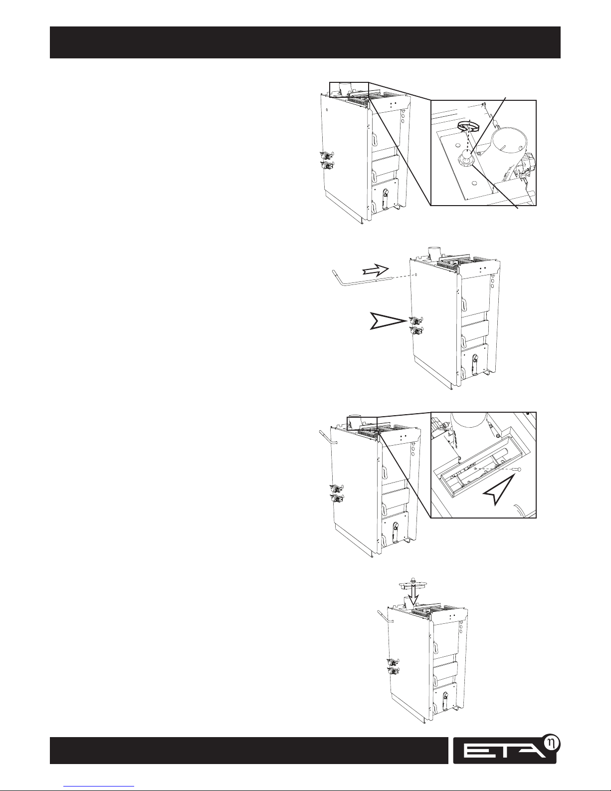
40
www.eta.co.at
180°
Cleaning lever for turbulators Installation
Insert cleaning lever for turbulators
Insert the cleaning lever into the boiler from the
side on which the actuators are installed.
Fasten cleaning lever for turbulators
Insert the cleaning lever into the turbulator
linkage and turn it towards the rear side of the
boiler.
Attach the cleaning lever to the turbulator linkage
with the bolt.
Close heat exchanger cover
Replace the heat exchanger cover.
Turn the fixing nut until it is as far up as possible.
Turn the ball knob clockwise as far as it will go.
Close the heat exchanger cover tightly with the
fixing nut.
Remove heat exchanger cover
Turn the fixing nut anti-clockwise to loosen it and
detach the ball knob by twisting it half a turn
anti-clockwise.
Then remove the heat exchanger cover.
Fixing nut
Ball knob
Page 41
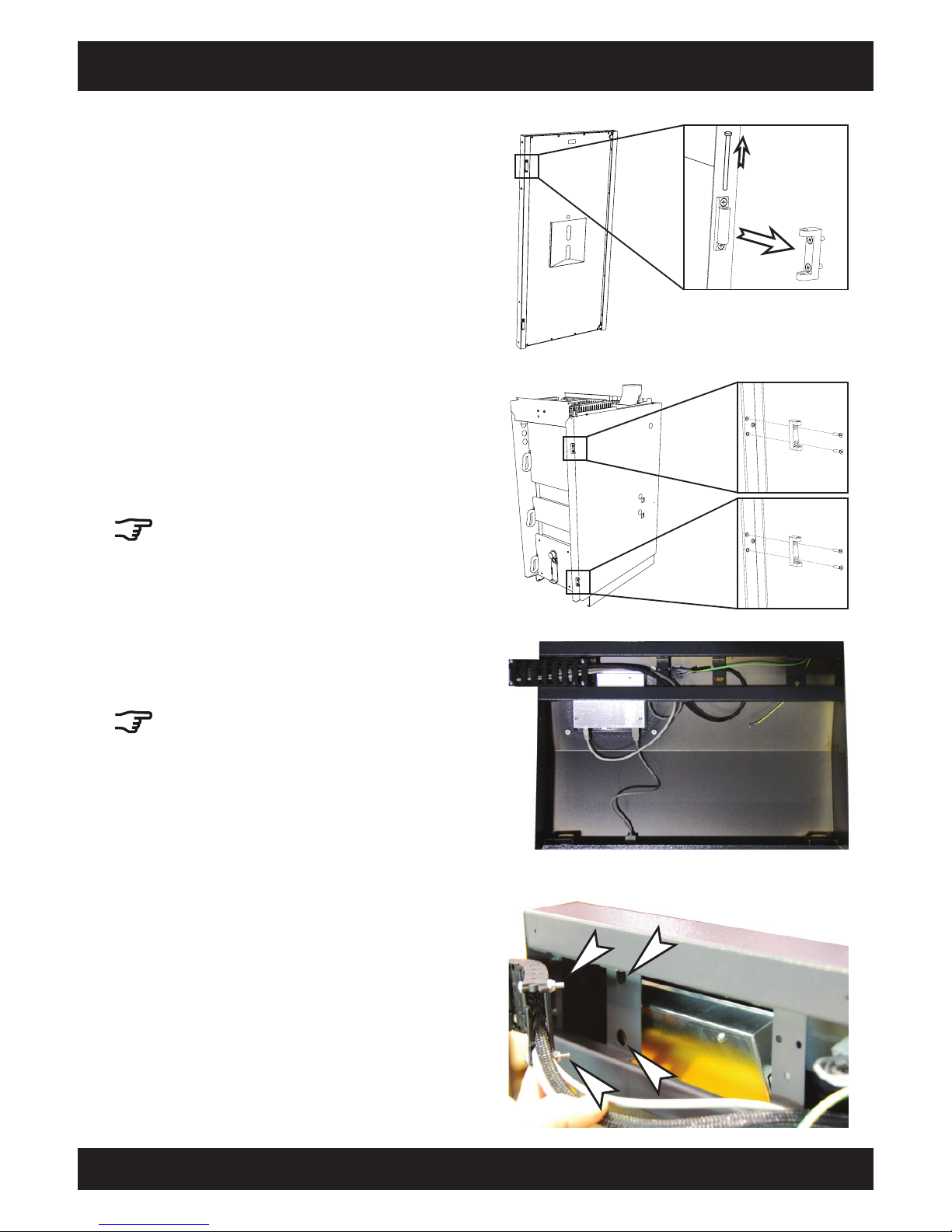
41
2012-11
Installation Insulation door, control panel
SH Montage
Install hinges for insulation door on door frame
The insulation door can be hinged on the right or
the left. In this description, the door is hinged on
the right side of the boiler.
Fasten both hinges to the door frame with 2 M5 x
20 countersunk screws each.
If the insulation door is hinged on the left, the
three boiler doors must also be reinstalled.
Disassemble hinges on insulation door
Lay the insulation door on a pallet and disassemble
the top and bottom hinges.
Insert cable chain into control panel
Insert the cable chain with cables into the control
panel as illustrated.
The cable chain must extend from the control
panel on the side on which the door hinges are
installed.
Insert cable chain bolts
Insert both cable chain bolts into the openings in
the control panel.
Page 42
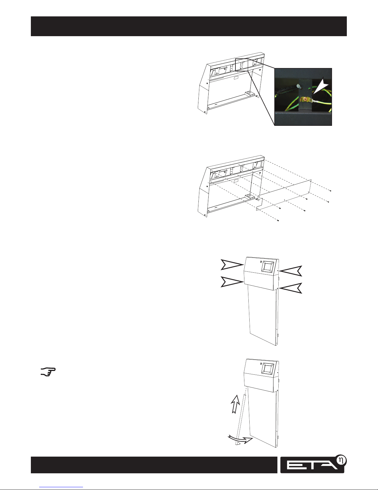
42
www.eta.co.at
Cleaning lever for turbulators Installation
Install cover on control panel
Screw the cover onto the control panel with 6 selftapping 3.5 x 9.5 screws.
Connect control panel earthing to insulation door
Lay the insulation door on the pallet with the inner
side facing down.
Connect the control panel's earthing cable to the
top side of the insulation door.
Attach control panel to insulation door
Place the control panel on the insulation door.
Fasten it with 4 M5 x 10 round-headed screws.
Insert door handle
The door handle must be installed on the side
opposite the hinges.
Insert the door handle at an angle into the opening
at the base of the control panel.
Page 43
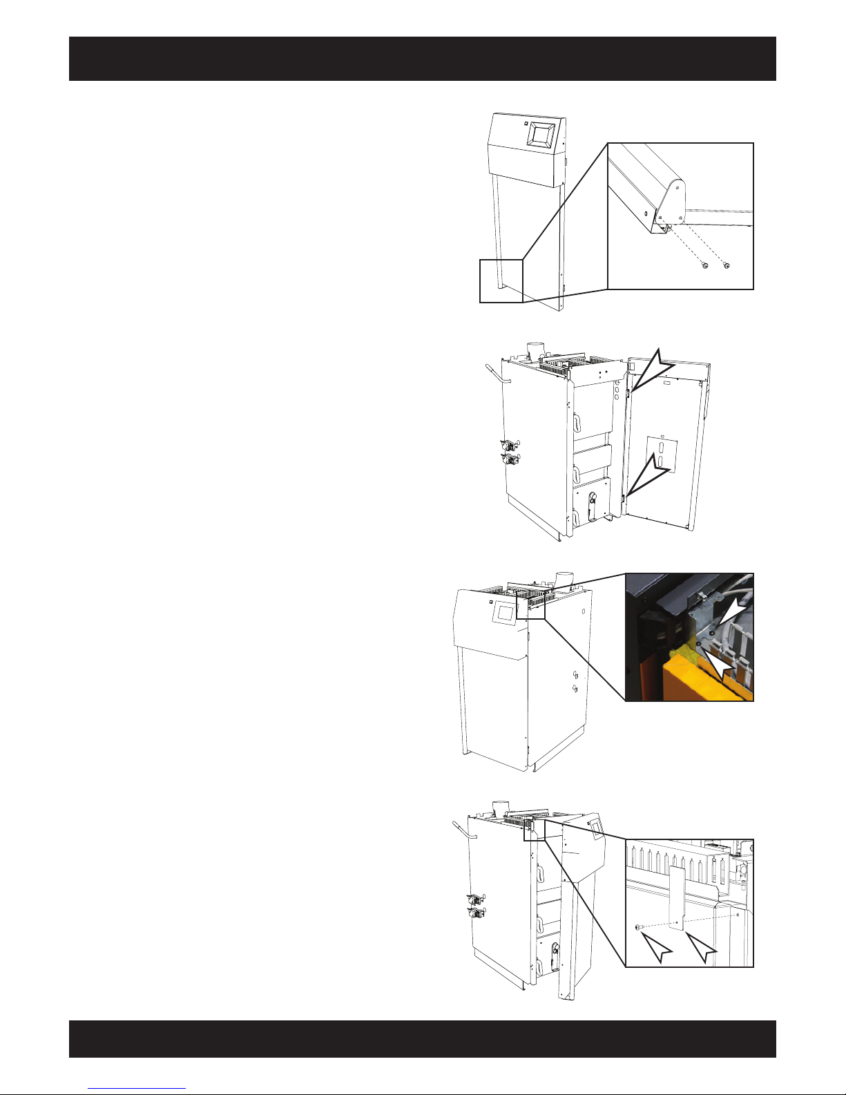
43
2012-11
Installation Cleaning lever for turbulators
SH Montage
Attach door handle
Fasten the door handle with 2 M5 x 10 roundheaded screws.
Install cable chain on boiler
Insert the cable chain behind the cover
and fasten the end of the chain to the circuit board
with 2 self-tapping 3.5 x 9.5 screws.
Install insulation door on boiler
Hang the insulation door on the hinges and secure
it with the hinge pins.
Screw cover onto door frame
Attach the cover to the door frame on the side
opposite the cable chain with a self-tapping 3.5 x
9.5 screw.
Page 44
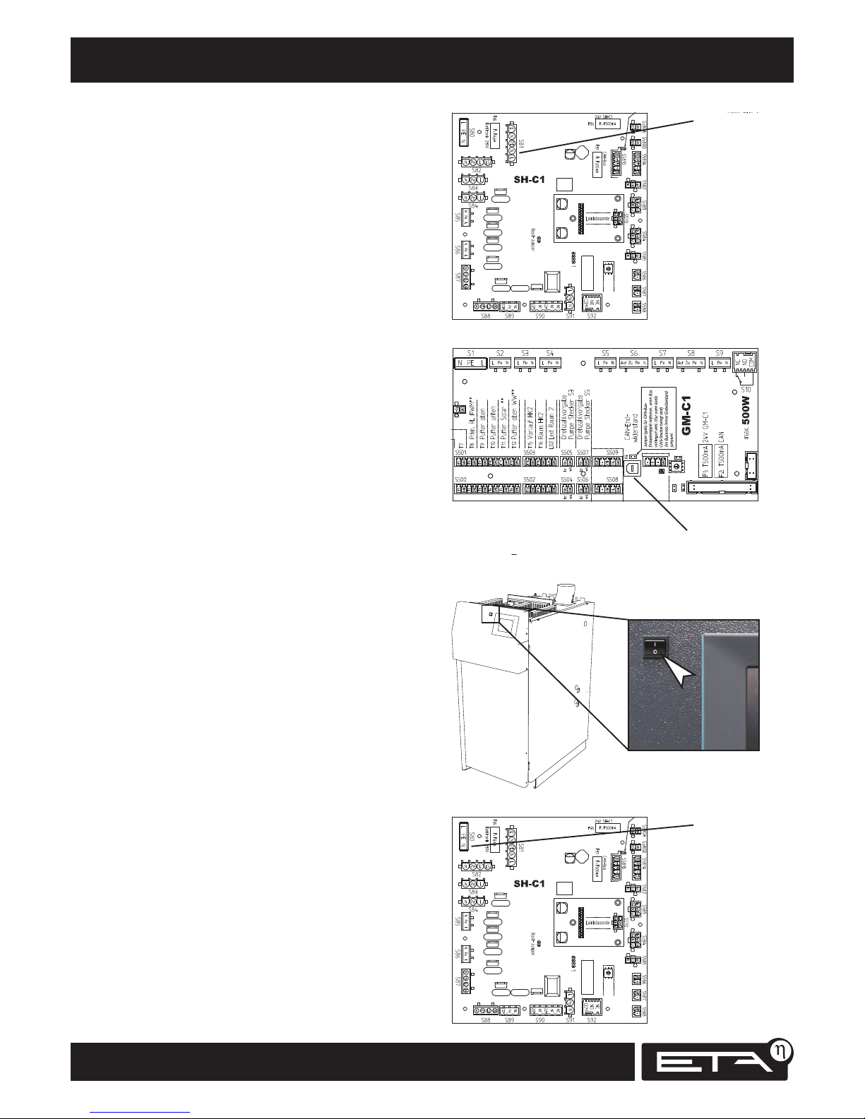
44
www.eta.co.at
S81
CAN Bus
S80
Cleaning lever for turbulators Installation
Switch off boiler with main switch
Switch the main switch on the boiler to the off
position.
Connect control system's power plug
Connect the cable to the SH-C circuit board at the
S81 terminal.
Connect CAN bus to control system
Connect the cable to the GM-C circuit board.
Connect boiler's power supply
Make the electrical connection to the boiler:
Supply cable 3 x 1.5² with flexible wires 230 V AC /
50 Hz C13 A / L+N+PE
Connect the cable to the SH-C circuit board at the
S80 terminal.
Page 45
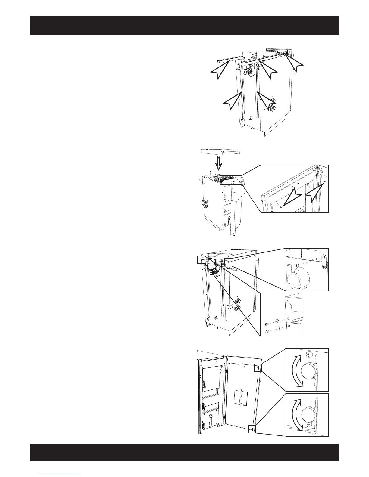
45
2012-11
Installation Panel on top side of boiler
SH Montage
Close all cable ducts
Lay all cables in the cable ducts and close the
covers of the cable ducts.
Fasten the panel to the rear of the boiler with 3
round-headed M5 x 10 screws and the galvanized
brackets on the side panels.
Tighten the two round-headed screws in front
on the door frame.
Install panel on top of boiler
Place the panel on top of the boiler and fit it to the
door frame at the front.
Screw both M5 x 10 round-headed screws into the
door frame (do not tighten yet).
Adjust insulation door
The separation between the insulation door and
the door frame can be adjusted by turning the
magnets so that the door closes properly.
Page 46
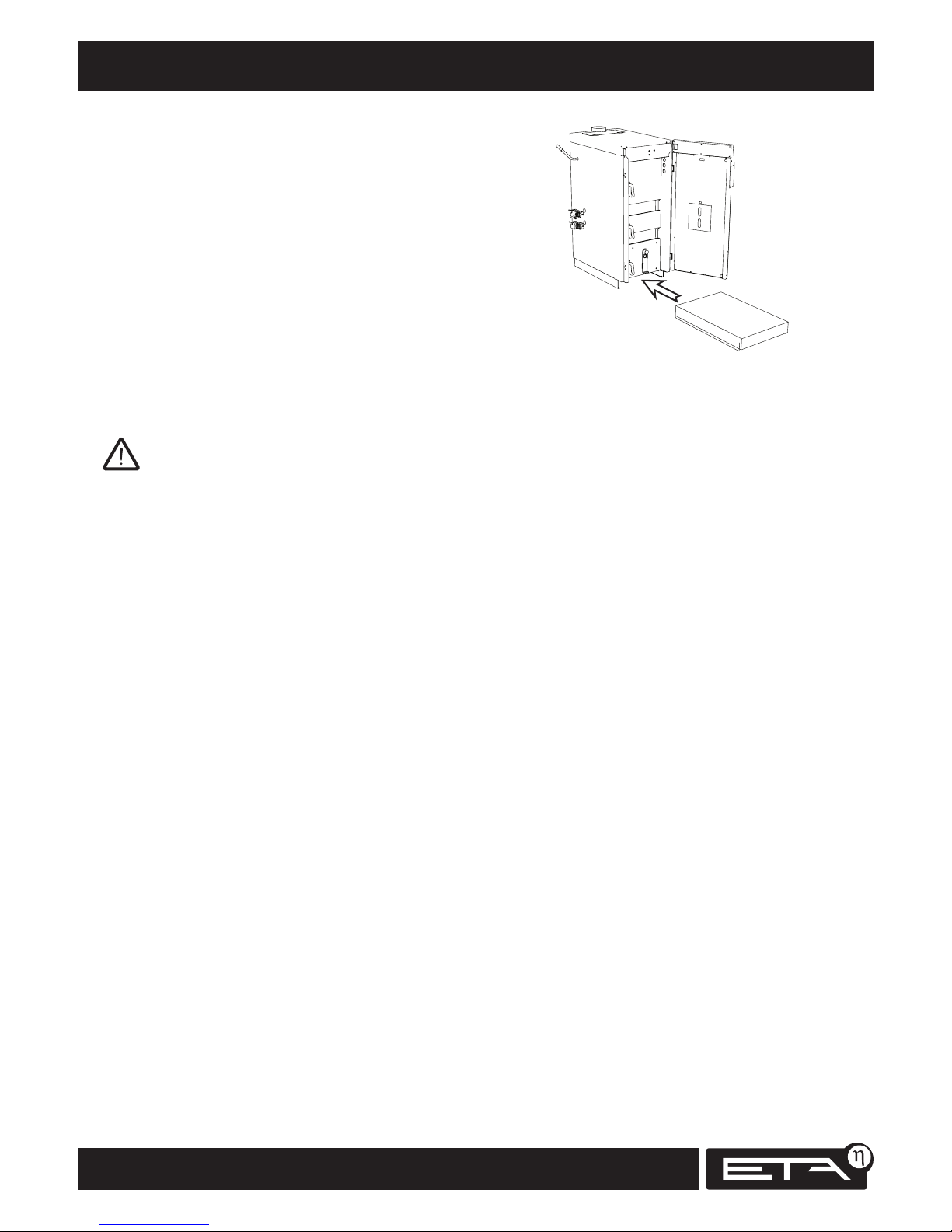
46
www.eta.co.at
Insulation at base of boiler Installation
Remove plastic protective film
Remove all protective film from the housing parts.
After longer operation of the boiler, the film can no
longer be removed without damaging the paint.
Place insulation under base of boiler
Push the insulation under the base of the boiler.
Page 47

47
2012-11
SH Montage
Page 48
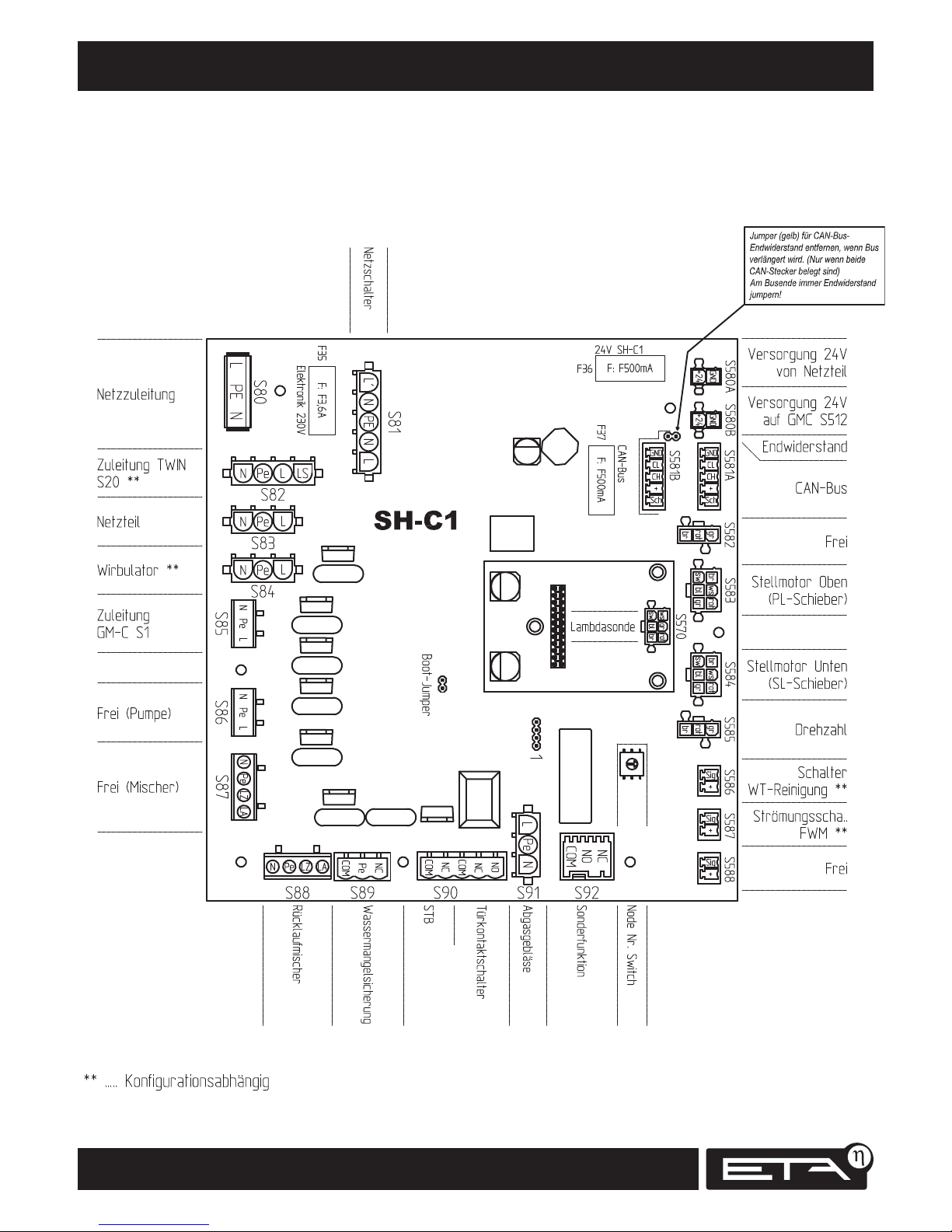
48
www.eta.co.at
Terminal diagram Electrical installation
Page 49
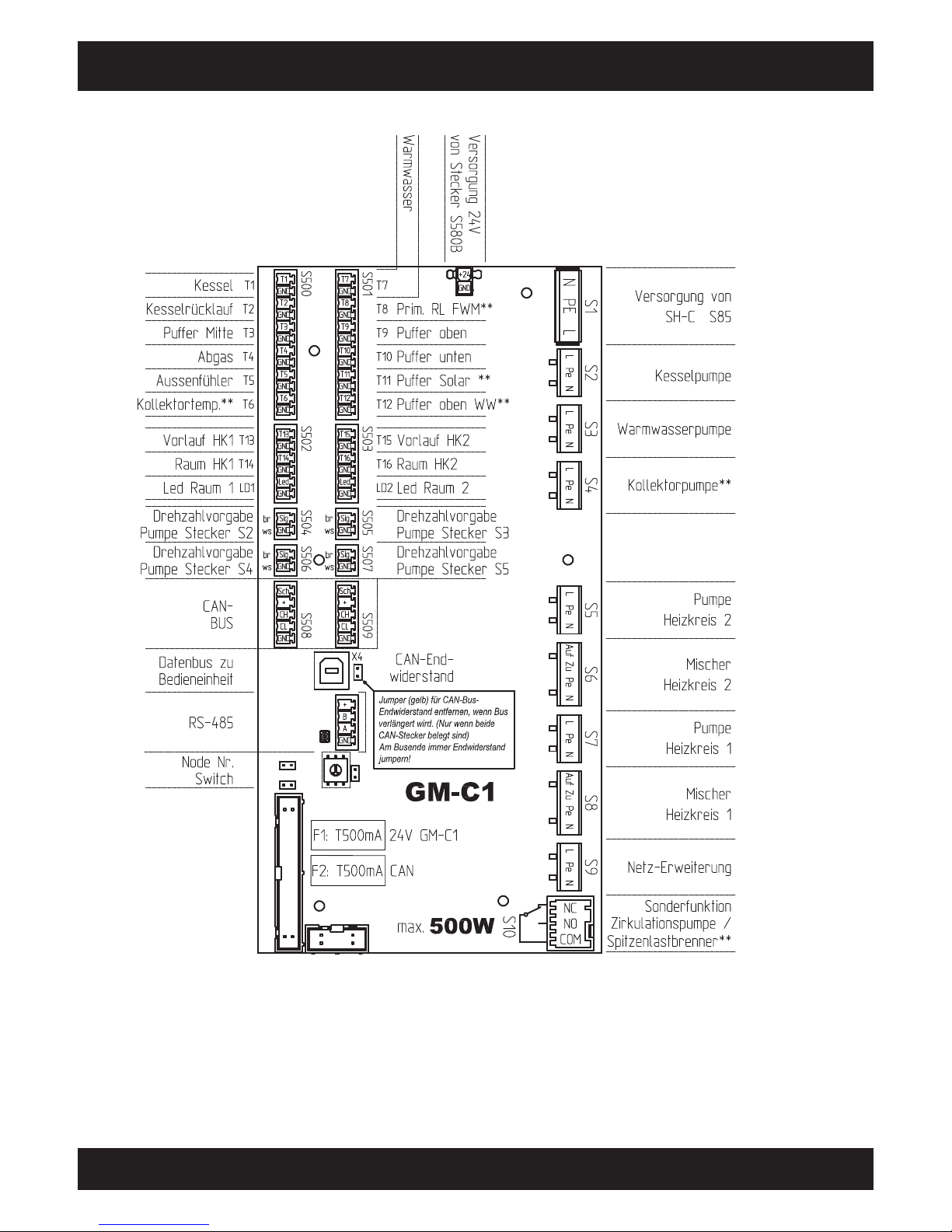
49
2012-11
Electrical installation Terminal diagram
SH Montage
Page 50
50
www.eta.co.at
Checklist for proper installation
Boiler installation
Minimum wall clearances maintained (space for maintenance)
Return temperature riser with mixing valve dimensioned for minimum return temperature 60°C
Piping in vicinity of return temperature measurement point insulated over a length of at least 20 cm
Dry boiler room
Frost-proof installation or filled with antifreeze or at least electric heater in buffer
Sufficient air inlets/outlets in Austria (ÖN H 5170):
Air supply 2 cm² per kW of fuel thermal input, at least 200 cm² free cross-section, for up to 100 kW rated heat
output, outlet at least 180 cm² free cross-section and for every additional kW another 1 cm², for wire screens at
least 20% extra, for air flow through ducts longer than 1 m larger cross-sections and documented calculations
Sufficient ventilation in Germany (MFeuVO):
up to 35 kW with door/window to the outside and room volume of 4 m³/kW, no special measures for combustion
air supply (this rule is not applicable for sealed windows and doors), 35 to 50 kW at least 150 cm² free ventilation
cross-section, over 50 kW at least 150 cm² free ventilation cross-section + 2 cm² per kW over 50 kW, for wire
screens at least 20% extra, for air flow through ducts considerably larger cross-sections (50 to 150% larger ->
calculate)
Safety
Safety valve without shut-off on boiler outlet
Safety valve on hot water side in hot water supply
Safety valve on buffer storage tank if it is also solar-charged
All safety valves without shut-off have visible drain via siphon funnel to sewer; if no sewer is available then piping
to floor (to prevent scalding)
Safety heat exchanger with thermally actuated drain valve connected to cold water inlet and with visible drain to
sewer. If no sewer is available under the thermal emergency cooling valve, then run pressure-resistant piping to
drain to the available sewer connection.
Pressure gauge
Fire extinguisher outside boiler room, easily visible and easily accessible (either in hall or stairwell)
Air venting, pressure equalisation and system separation
Air valve directly adjacent to boiler outlet and at highest point in flow pipe
Air valves in flow of each heating circuit at highest point
Air valve on buffer storage tank
Expansion tank with gross capacity 10% of system volume, installed directly in return between boiler and buffer,
actuating levers or hand wheels removed from all shut-off valves between expansion tank, boiler and buffer
No open expansion tank
Impermeable piping for underfloor heating with up to 3,000 running metres of piping, over 3,000 running metres
of piping with system separation (even for impermeable piping)
Softened water
Softened water for initial fill-up: maximum 20,000 lt°dH (system volume in litres multiplied by hardness in degrees
of German hardness). Softening after heating up the boiler is too late because the lime has already been deposited
on the boiler walls.
To keep water replacement (and the resulting new lime content) during repairs to a minimum, install enough
shut-off valves (especially on the buffer connections), and filling and drainage valves for each area that can be shut
off individually.
Page 51
51
2012-11
Checklist for proper installation
SH Montage
Buffer storage tanks
Sufficient volume for SH20 and SH30 at least 1,100 litres (for underfloor heating) and optimally 2,000 litres (for
radiator heating), for SH40 to SH60 at least 2,200 litres (for underfloor heating) and optimally 3,000 litres (for
radiator heating)
In Germany according to 1.BlmSchV:
for SH20 1,100 litres, for SH30 1,650 litres, for SH40 2,200 litres, for SH50 2,750 litres, for SH60 3,300 litres
For parallel connected buffers with 5/4" DN32 connections (values for 6/4" DN40 in parentheses):
for two buffers up to 25 (40) kW one-sided connection possible, for two buffers up to 80 (130) kW internal
Tichelmann connection, over 80 (130) kW external piping symmetrical or Tichelmann, for more than two buffers,
always external Tichelmann connection, serial connection only for buffers set up in separate locations, combination
tanks are not suitable for serial connection
Shut-off valves on all buffer connections (minimises drainage volume - minimum lime content)
"Buffer bottom" sensor for boiler installed above (not below) associated return connection
Return temperature from system low enough to achieve the required storage capacity
Sufficiently adjustable radiator valves installed in all radiators (especially in WC, anteroom and other auxiliary
rooms)
Air heat exchangers throttled to amount of water actually needed or, better still, return temperature limited with
thermal control valve
Chimney
Chimney diameter is no more than 40% larger than optimum diameter from table
Multi-layered, insulated, moisture-resistant chimney or chimney renovation with inserted pipe
Draught limiter for moisture-sensitive chimneys to dry them during combustion breaks, set to 5 to 10 Pa. Minimum
exhaust temperature limited to 180°C for moisture-sensitive chimneys
Chimney opening at least 2 m higher than the eaves of neighbouring houses
Condensate drainage with siphon from chimney to sewer
Connection pipe from boiler to chimney, short with few bends, thermally insulated, ascending
Flue pipe inserted into chimney sleeve with padded seal (structure-borne noise)
Accessible cleaning apertures in chimney and flue pipe bends
For long, horizontal connections between boiler and chimney (L > 30d), a deflagration damper is required above the
boiler, installed so that no persons are endangered
Hot water supply
Sufficiently large heat exchanger in hot water tank, at least 1.5 m²
Small charging pump for the hot water tank (2 m pump), lowest required speed
Heat flow meter
Heat flow meter in return between heat distributor and mixing valve bypass (in area where temperature spread is
still high)
At least 20°C spread between flow and return to keep measurement error under 10%
Piping in vicinity of temperature measurement points insulated over a length of at least 200 mm
Fuel
Air-dried wood, water content less than 20% (cut in previous winter and stored over the summer)
Average cross-section of half-metre logs less than 120 mm
If fuel is stored outdoors, cover with rainproof covering
Page 52

52
www.eta.co.at
 Loading...