

Page 1
2017-01-09
EN
0000000295
V.002
X.38.0
3004, 3105
93528-001
Wood chip boiler
20 - 90 kW
Service manual
Page 2

ETA Heiztechnik
Gewerbepark 1
A-4716 Hofkirchen an der Trattnach
Tel: +43 (0) 7734 / 22 88 -0
Fax: +43 (0) 7734 / 22 88 -22
info@eta.co.at
www.eta.co.at
Page 3
General information
3
1 General information
Support for cleaning and maintenance
This document helps support you with the cleaning
and maintenance of the boiler. The required steps are
listed in detail here.
Take note of the date of the cleaning or maintenance
and any faults that may have occurred. This facilitates
troubleshooting for the expert (system operator,
heating technician...).
For services (such as commissioning, mainte-
nance, fault fixing provided by ETA customer
service), the service reports are provided in digital
form. For clarity , you should staple th ese reports to this
document or enclose them.
Commissioning data
Enter the boiler number (printed on the type plate), the
date of commissioning as well as the heating
technician who commissioned the system.
Copyright
All contents of this document are property of ETA
Heiztechnik GmbH and are protected by copyright.
Any reproduction, transfer to third parties or use for
other purposes is prohibited without written permission
from the owner.
Subject to technical changes
We reserve the right to make technical modifications
without notice. Printing and typesetting errors or
changes of any kind made in the interim are not cause
for claims. Individual configurations depicted or
described here are only available optionally. In the
event of contradictions between individual documents
regarding delivery scope, the information in our current
price list applies.
Explanation of symbols
Instructions and information
Layout of safety instructions
SIGNAL WORD!
Type and source of danger
Possible effects
• Measures for avoiding the danger
Types of safety instruction
CAUTION!
On non-compliance with this safety instruction, there is
a risk of material damage.
WARNING!
On non-compliance with this safety instruction, there is
a risk of physical injury.
DANGER!
On non-compliance with this safety instruction, there is
a risk of major physical injury.
Commissioning data
Boiler number:
________________________________________
Commissioned on:
_________________________________________
Commissioned by (company):
_________________________________________
_________________________________________
_________________________________________
Page 4
4 www.eta.co.at
Maintenance notes Cleaning and maintenance
2 Cleaning and maintenance
2.1 Maintenance notes
Performing regular cleaning and maintenance
To ensure satisfactory functioning, cleaning and
maintenance must be performed at regular intervals.
Carry out this work within the intervals stated here.
All tasks where the maintenance table reads
"Customer" or "Customer or expert" in the column
"T o b e carried out by" can be carr ied out by any trained
adult. Instructions can be provided by the heating
technician or our customer service.
Steps that are marked with "Expert" only can only be
carried out by the heating tech nician or our customer
service.
Operation only by trained personnel
The product may be operated by trained adults only.
Training may be provided by the heating technician or
our customer service. Please read the associated documentation carefully in order to avoid errors during
operation and maintenance.
Persons who lack experience and knowledge as well
as children may not operate, clean, or maintain the
product.
Explanation of pictograms
Switch the boiler on/off with the mains switch.
Perform a visual check of the components.
Clean the components, for example, with a
soft cloth.
Remove deposits with a vacuum or an ash
vacuum.
Remove deposits with the poker.
Remove deposits with the cleaning brush.
Replace the wear parts (e.g. seals) on the
components.
Lubricate the components. The lubricant to
use is listed in the respective step.
Install the components with some force (for
example the retaining tube or the Lambda
probe).
Handle the components carefully, since they
break very easily.
Clean panels
If necessary, clean the panels of the boiler and the
ETAtouch screen with a moist cloth.
Under no circumstances use aggressive
solvents, chemicals or scouring agent s. They can
lead to stress cracks and damage.
Checking the boiler counters
The counters can be seen in the boiler's text menu.
Counter [Full load hours since maint.] is used for the
service intervals. If it has reached one of the listed
intervals, maintenance is required. This counter is in:
Counters
Full load hours since maint.
Page 5

Cleaning and maintenance Maintenance notes
5
Page 6

6 www.eta.co.at
Maintenance openings in the boiler Cleaning and maintenance
2.2 Maintenance openings in the
boiler
Maintenance openings and components
The illustrations show a boiler with a size of 2 (63
- 90 kW) with its fuel discharge on the left side.
The fuel discharge depicted here is the standard configuration.
1 Combustion chamber door
2 Secondary air actuator (mirrored for fuel discharg e
installed on the right)
3 Actuator for tilting grate
4 Maintenance cover for optional flue gas recircula-
tion
5 Primary air actuator (mirrored for fuel discharge
installed on the right)
6 Firebed switch (mirrored for fuel discharge
installed on the right)
7 Safety switch for rotary valve maintenance cover
8 Plug screw for lubricating the stoker drive chain
9 Turnbuckle for the stoker drive chain
10 Drop chute safety switch
11 Drop chute maintenance cover
Page 7

Cleaning and maintenance Maintenance openings in the boiler
7
1 Shut-off plug for optional flue gas recirculation
2 Maintenance cover for optional flue gas recircula-
tion
3 Flue gas temperature sensor
4 Heat exchanger cleaner
5 Ignition
6 Stoker drive chain
7 Maintenance cover for optional flue gas recircula-
tion
8 Plug screw for lubricating the de-ashing system's
drive chain
9 Draught fan
Page 8
8 www.eta.co.at
Maintenance table Cleaning and maintenance
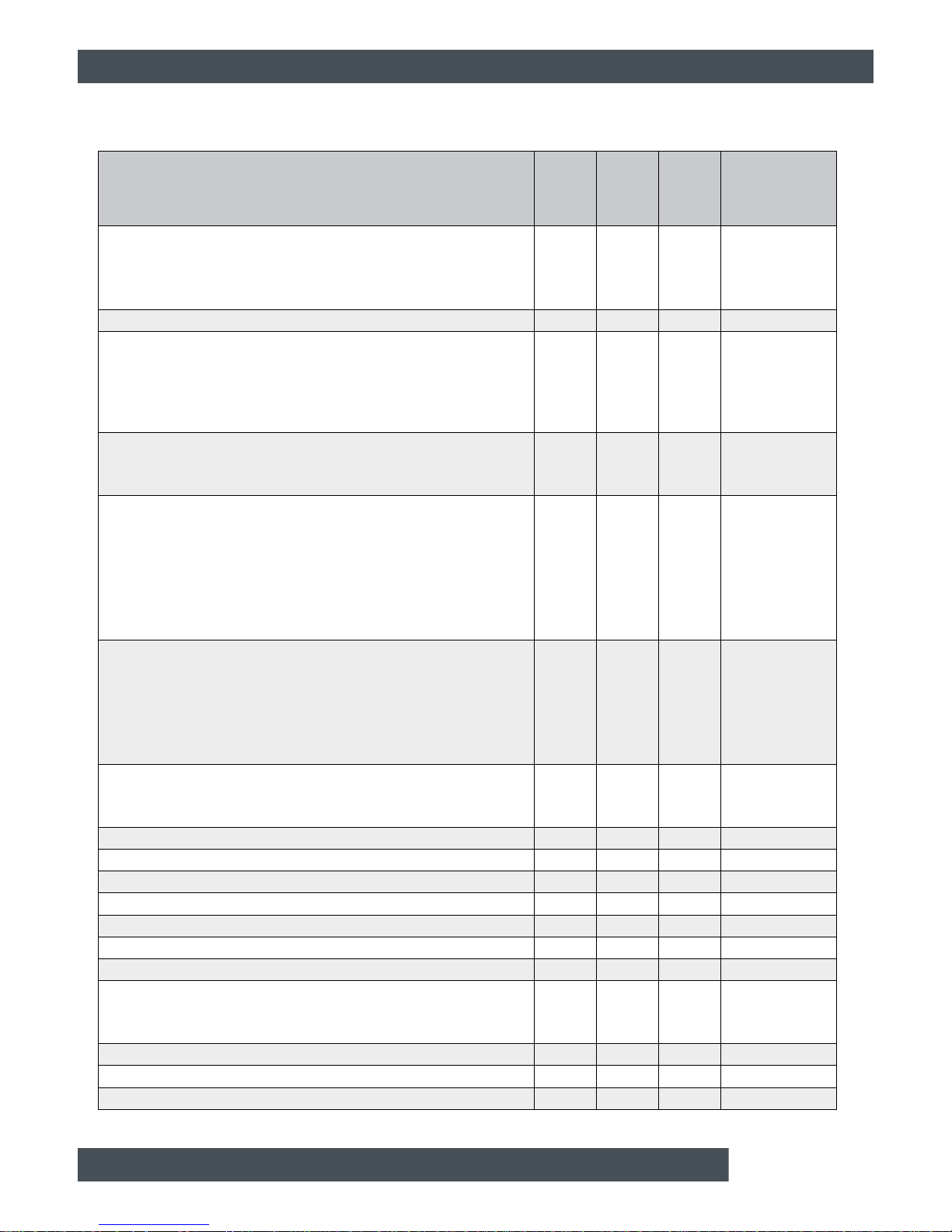
2.3 Maintenance table
Tasks
Regular
ly
Every
2500 h
or
1 year
Every
5000 h
or
3years
to be
performed by
Empty the ash box
• Remove excess ash from secondary combustion chamber
• Empty the ash box
• Check the seals
X X X Customer
Check the pressure of the heating system X X X Customer
Check safety devices
• Visual check of the safety valves
• Visual check of the thermal relief valve
• Check operational readiness of the safety devices in the fuel
path
X X
Customer or
specialist
Chimney
• Clean the flue tube
• Flush the chimney's condensate drain
X X
Customer or
specialist
Clean combustion chamber
• Clean inside of the secondary combustion chamber
• Clean tilting grate
• Clean secondary air openings
• Clean the ignition tube
• Check firebed button and firebed switch
• Check refractory lining
X X
Customer or
specialist
Clean heat exchanger
• Clean heat exchanger and downdraft channel
• Clean lambda probe
• Check heat exchanger tubes
• Check heat exchanger cleaner
• Check seal on heat exchanger cover
X X
Customer or
specialist
Clean flue gas recirculator (optional)
• Clean flue gas recirculation piping
• Inspecting seals on maintenance covers
X X
Customer or
specialist
Clean the draught fan X Specialist
Clean the temperature sensor X Specialist
Check air valve for primary and secondary air X Specialist
Check the ash box position switch X Specialist
Check de-ashing system X Specialist
Clean ignition X Specialist
Check boiler doors X Specialist
Check stoker
• Check stoker drive chain
• Check gap of the rotary valve position sensor
X Specialist
Check drop chute safety switch X Specialist
Check end position of the rotary valve X Specialist
Calibrate the lambda probe X Specialist
Page 9
Cleaning and maintenance Maintenance table
9
Reset the maintenance counter X Specialist
Perform heating test X Specialist
Tasks
Regular
ly
Every
2500 h
or
1 year
Every
5000 h
or
3years
to be
performed by
Page 10

10 www.eta.co.at
Regularly Cleaning and maintenance
2.4 Regularly
2.4.1 Preparation
Stop heating
End the boiler's heating mode with the On/Off switch
in the boiler overview window. The boiler
performs an ember burnout and then changes to
[Switched off] mode. Press the [De-ash] button to
make the boiler perform a final de-ashing.
2.4.2 Empty the ash box
Remove excess ash from secondary combustion
chamber
Open the combustion chamber door and use the poker
to scrape the excess ash into the combustion
chamber.
The ash in the secondary combustion chamber
may not be steeper than 45°.
To remove this ash, initiate boiler de-ashing by
pressing the [De-ash] button.
Empty the ash box, inspect the seals
By knocking on the vertical wall of the ash box,
you can also check the ash level without opening
the box. A full ash box makes a short, dull thump.
When empty it makes a hollower sound like a drum.
Open both lateral fasteners by pressing their safety
catches in the direction of the arrow. Remove the ash
box from the boiler.
Fig. 2-1: Fastener
Remove the lid by opening the fastener s and empty
the ash box.
Fig. 2-2: Check ash
If there are large pieces of slag in the ash, the
combustion chamber and the tilting grate must be
checked and the de-ashing interval reduced, if
necessary.
Page 11

Cleaning and maintenance Regularly
11
Inspect the seal on the ash box lid to ensure it is in
good order, and replace it if necessary.
Fig. 2-3: Seal
Inspect the integrity of the ash box seals on the boiler,
replace them if necessary.
Fig. 2-4: Seal
Attaching the ash box to the boiler
Reattach the cover of the ash box and secure with the
fasteners. Push the ash box over the connection on
the boiler and attach it to the boiler with the fasteners.
2.4.3 Check pressure of the heating
system
Check heating system water pressure
In buildings with up to three storeys, the optimum
water pressure in a cold heating s ystem is betwee n 1
and 2 bar. For a warm heating system, the optimum
water pressure is between 1.5 and 2.5 bar.
Fig. 2-5: Pressure gauge
If the water pressure is too low, fill the cold
heating system to approx. 2 bar. Do not fill to a
higher pressure, as water expands with increasing
temperature and the water pressure al so rises when
the boiler is in heating mode. The safety valve triggers
at approx. 2.8 bar.
If the water pressure drops several times a year,
contact a heating professional. When refilling
water in the heating system, the same water as used
during initial filling should be used whenever possible
(e.g. prepared water).
2.4.4 Establish operational readiness
Switching on the boiler
Switch the boiler back on with the On/Off
switch.
Page 12
12 www.eta.co.at
2500 h / annually Cleaning and maintenance
2.5 2500 h / annually
2.5.1 Preparation
Stop heating
End the boiler's heating mode with the On/Off switch
in the boiler overview window. The boiler
performs an ember burnout and then changes to
[Switched off] mode. Press the [De-ash] button to
make the boiler perform a final de-ashing.
Switch off boiler via mains switch
WARNING!
Switch off the electricity to the boiler via the mains
switch. This prevents injuries caused by switching
the boiler on inadvertently.
WARNING!
Burns caused by hot parts
Risk of burning on parts located behind the
boiler housing, even after shutting the boiler
down.
Allow the boiler to cool down sufficiently
before starting any activities.
2.5.2 Check safety devices
Checking the safety valves
Perform a visual check of all safety valves of the
heating system. The outlets of the safety valves may
not drip.
Fig. 2-6: Safety valve
If the safety valve drips, open it with a quarter turn of
the red cap and rinse it out (danger of scalding). If the
safety valve still cannot be sealed effectively after
being rinsed several times, it must be cleaned or
replaced by an installer (heating technician).
A manual check of the safety valve is carried out
with a 1/4 turn of the red cap. This rinses the
safety valve. However it is very likely that the seal will
be damaged in the process and thus the outlet will drip.
That is why you should only perform this check on
weekdays and never on weekends in cold winter , as no
heating technician may be available if the seal is
defective.
Check function of safety devices in fuel path
Check the safety devices in the fuel path, such as the
temperature-monitoring system, the manually
operated extinguishing system or the automatic extinguishing system.
Also check malfunction indicators and alarms, for
example if messages from the boiler room are
displayed elsewhere.
Page 13

Cleaning and maintenance 2500 h / annually
13
Checking the thermal relief valve
Visually examine the thermal relief valve. The outlet
should not drip.
Fig. 2-7: Thermally actuated drain valve
If the relief valve is dripping, rinse it by pressing the red
button (risk of scalding). If the relief valve still cannot
be closed tightly after being rinsed several times, it
must be cleaned by an installer (heating technician) o r
replaced.
A manual check of the relief valve is carried out
by pressing the red button. This rins es the relief
valve. However it is very likely that the seal will be
damaged in the process and thus the outlet will drip.
That is why you should only perform this check on
weekdays and never on weekends in cold winter , as no
heating technician may be available if the seal is
defective.
2.5.3 Chimney
Clean the flue tube
Sweep the flue tube from the flue outlet to the chimney
and remove flue ash from the chimney using a vacuum
cleaner.
Fig. 2-8: Flue tube
Sweep the ash into the chimney, not into the
boiler. Otherwise, ash will collect in the
fan housing and can block the draught fan.
Rinse the chimney's condensate drain
Check the chimney's condensate drain to make sure it
is free, as ash can block the outlet. To check, rinse the
outlet with some water.
Fig. 2-9: Condensate drain
Page 14

14 www.eta.co.at
2500 h / annually Cleaning and maintenance
2.5.4 Cleaning the combustion chamber
Clean inside of the secondary combustion
chamber
Open the combustion chamber door an d scrape all of
the ash from the secondary combustion chamber into
the primary combustion chamber with the poker.
Fig. 2-10: Secondary combustion chamber
Remove the combustion chamber cover in the
secondary combustion chamber.
Fig. 2-11: Combustion chamber cover
Remove the cover on the front
Remove the screws for securing the cover. Push the
cover on the front up slightly, detach and remove it.
Fig. 2-12: Cover
Clean tilting grate
Press the button on the tilting grate's actuator and tilt
the grate with the supplied tool.
Fig. 2-13: Actuator
Use the poker to clean the tilting grate and the
openings in it; let the ash fall down.
Fig. 2-14: Tilting grate
Page 15

Cleaning and maintenance 2500 h / annually
15
Do not hit the tilting grate with the poker.
Clean secondary air openings
Clean secondary air openings (above the tilting grate).
Fig. 2-15: Secondary air openings
Clean the ignition tube
Check the ignition tube for combustion residues and
clean it by vacuuming.
Fig. 2-16: Ignition tube
Check firebed button and firebed switch
Check the mobility of the firebed button in the
combustion chamber by repeated lifting.
Fig. 2-17: Firebed button
The firebed switch on the front of the boiler must be
actuated when lifting.
Fig. 2-18: Firebed switch
Check refractory lining
Check the refractory lining of the primary and
secondary combustion chambers for damage and
cracks.
Page 16

16 www.eta.co.at
2500 h / annually Cleaning and maintenance
Replace the combustion chamber cover
Reinsert the combustion chamber cover , ensur ing that
it is properly centred.
Fig. 2-19: Combustion chamber cover
The convex surface of the combust ion chamber
cover must point to the top of the boiler.
Mount cover on the front
Mount the cover on the front of the boiler . Also re-install
the screws for securing the cover.
Fig. 2-20: Cover
2.5.5 Cleaning the heat exchanger
Remove heat exchanger cover
Open the maintenance cover in the top of the boiler
casing and remove the insulating cover.
Fig. 2-21: Insulating cover
Loosen the knurled nuts on the heat exchanger cover
by turning it anti-clockwise and rotate the ball knobs by
180°.
Fig. 2-22: Knurled nuts and ball knobs
Remove the heat exchanger cover.
Fig. 2-23: Heat exchanger cover
Page 17

Cleaning and maintenance 2500 h / annually
17
Clean heat exchanger and downdraft channel
Remove the internal cover between the secondary
combustion chamber and the heat exch an g er.
Fig. 2-24: Internal cover
Brush out the downdraft channel and rem ove the flue
ash from the heat exchanger, for example with an
ash vacuum.
Fig. 2-25: Heat exchanger and downdraft channel
After cleaning, replace the internal cover. Ensure that
it is firmly seated.
Clean lambda probe
Vacuum out the head of the lambda probe using a
vacuum cleaner. Do not dismantle the lambda probe.
Fig. 2-26: Head of the lambda probe
Check heat exchanger tubes
Check the heat exchanger tubes and the turbulators
for tar deposits.
Fig. 2-27: Heat exchanger tubes
Page 18

18 www.eta.co.at
2500 h / annually Cleaning and maintenance
Tar deposits can have several causes, for
example:
• leak air through the heat exchanger cover, the
combustion chamber door or the lambda probe.
• an incorrectly calibrated lambda probe
• overly moist wood chips
• insufficient boiler runtime (start-stop operation)
Check heat exchanger cleaner
Remove the cover for the heat exchanger cleaner
drive.
Fig. 2-28: Cover
Manually operate the lever and check its ease of
movement. Lubricate the spring, guide and bearing
with a heat-resistant lubricant.
Fig. 2-29: Lever
Check the gap between the sensor and the spring a rm.
It must be 2 mm.
Fig. 2-30: Position sensor
Finally, re-attach the cover to the boiler.
Check seal on heat exchanger cover
Inspect the integrity of the seal on the heat exchanger
cover and replace if necessary.
Fig. 2-31: Heat exchanger cover
Page 19

Cleaning and maintenance 2500 h / annually
19
CAUTION!
Avoid operation with damaged seals
Never operate the boiler with damaged seals.
Otherwise, leak air is sucked in, disturbing the
combustion process and causing increased wear.
Always replace seals as soon as they are
damaged.
Close heat exchanger cover
Position the heat exchanger cover carefully.
Fig. 2-32: Heat exchanger cover
Turn both ball knobs through 180° to secure the heat
exchanger cover. Then tighten the two knurled nuts
evenly and cross-wise by turning them clockwise.
Fig. 2-33: Knurled nuts and ball knobs
Put the insulating cover back on.
Fig. 2-34: Insulating cover
Page 20

20 www.eta.co.at
2500 h / annually Cleaning and maintenance
2.5.6 Clean flue gas recirculator (optional)
Remove the maintenance cover for flue gas recirculation
Remove the two maintenance covers for the flue gas
recirculation from the back side of the boiler.
Fig. 2-35: Maintenance cover
Also remove the shut-off plug (if present).
Fig. 2-36: Shut-off plug
Also remove the two maintenance covers from the
front side of the boiler.
Fig. 2-37: Maintenance cover
Clean flue gas recirculation piping
Brush out the pipes of the flue gas recirculation with
the brush and remove the ash with a vacuum cleaner.
Fig. 2-38: Pipes
Fig. 2-39: Pipes
Page 21

Cleaning and maintenance 2500 h / annually
21
Also brush out and clean out the pipes on the front side
of the boiler.
Fig. 2-40: Pipes
Inspecting seals on maintenan ce co ve rs
Check all seals for the maintenance cover of the flue
gas recirculation to ensure they are in good condition,
replace if necessary.
Fig. 2-41: Seal
CAUTION!
Avoid operation with damaged seals
Never operate the boiler with damaged seals.
Otherwise, leak air is sucked in, disturbing the
combustion process and causing increased wear.
Always replace seals as soon as they are
damaged.
Re-install maintenance cover.
Replace the shut-off plug (if this was already installed).
Fig. 2-42: Shut-off plug
Re-install all maintenance covers for flue gas recirculation.
Fig. 2-43: Maintenance cover
Page 22

22 www.eta.co.at
2500 h / annually Cleaning and maintenance
Fig. 2-44: Maintenance cover
2.5.7 Establish operational readiness
Switch the boiler on via the mains switch and start
de-ashing.
Establish the boiler's power supply at the mains switch.
Press the [De-ash] button to de-ash the boiler.
Switch the boiler back on with the On/Off
switch.
Page 23

Cleaning and maintenance 5000 h / 3 years
23
2.6 5000 h / 3 years
2.6.1 Preparation
Before this maintenance, perform all steps for the
preceding maintenance intervals
Before this maintenance, all steps for the
preceding maintenance intervals must be
performed.
WARNING!
The following activities may only be performed by
qualified specialist personnel.
If you carry out these activities without the corresponding specialist training, and above all without the
required experience, safe operation is no longer
guaranteed. The resulting defects and consequential
damage are excluded from the guarantee and
warranty.
Equally an incorrect performance of these activities
can lead to serious injuries.
Stop heating
End the boiler's heating mode with the On/Off switch
in the boiler overview window. The boiler
performs an ember burnout and then changes to
[Switched off] mode. Press the [De-ash] button to
make the boiler perform a final de-ashing.
Switch off boiler via mains switch
WARNING!
Switch off the electricity to the boiler via the mains
switch. This prevents injuries caused by switching
the boiler on inadvertently.
WARNING!
Burns caused by hot parts
Risk of burning on parts located behind the
boiler housing, even after shutting the boiler
down.
Allow the boiler to cool down sufficiently
before starting any activities.
2.6.2 Clean draught fan
Clean the draught fan
Unplug the power supply and remove the draught fan
from the boiler by removing the wing screws.
Fig. 2-45: Draught fan
Remove the ash from the fan housing on the boiler.
Fig. 2-46: Clean the fan housing
Carefully clean the impeller of the draught fan with a
soft brush (not a wire brush) or with compresse d air , so
that the impeller does not move out of balance.
Replace the seal on the draught fan.
Fig. 2-47: Clean impeller; replace seal
Page 24

24 www.eta.co.at
5000 h / 3 years Cleaning and maintenance
Lubricate the screws with heat-resistant lubricant and
reattach the draught fan to the fan housing. T ighten the
screws evenly. The plug connection must point to the
right when viewed from behind the boiler.
2.6.3 Clean temperature sensor
Clean the flue gas temperature sensor
To clean, loosen the screw and pull out the flue gas
temperature sensor. Clean the sensor with a soft cloth
and then re-install it. When fixing the temperature
sensor in place, only tighten the screw hand-tight so as
not to damage the sensor.
Fig. 2-48: Flue gas temperature sensor
Page 25

Cleaning and maintenance 5000 h / 3 years
25
2.6.4 Check air valve
Remove the cover on the front
Remove the screws for securing the cover. Push the
cover on the front up slightly, detach and remove it.
Fig. 2-49: Cover
Check air valve
Manually operate both air valve ac tuators and check
their movement.
Fig. 2-50: Air valve actuators
For manual operation, push the release button (red
button) and manually turn the actuator through 90°
with the set screw.
Fig. 2-51: Manual operation of actuator
1 Set screw
2 Release button
If there is resistance in the movement of the air
valves, lubricate only with dry lubricant (e.g.
PTFE spray).
Mount cover on the front
Mount the cover on the front of the boiler . Also re-install
the screws for securing the cover.
Fig. 2-52: Cover
Page 26

26 www.eta.co.at
5000 h / 3 years Cleaning and maintenance
2.6.5 Check ash box position switch
Check the ash box position switch
Inspect the function of the ash box position switch. It
must be actuated when the ash box is fitted.
Fig. 2-53: Position switch for ash box
2.6.6 Check de-ashing
Lubricating the de-ashing drive chain
On the rear of the boiler, remove the plug screw from
the cover next to the de-ashing drive.
Fig. 2-54: Plug screw
Through this opening, lubricate the de-ashing drive
chain with chain spray. The easiest way to do this is to
start de-ashing. This sets the chain in motion so it can
be completely lubricated.
Check de-ashing system
Start de-ashing in order to check de-ashing of the
boiler. The movement of the turbulators in the heat
exchanger must be audible, the tilting grate must tip
and then close again, and the ash screws must
operate without malfunction.
Page 27

Cleaning and maintenance 5000 h / 3 years
27
2.6.7 Clean ignition
Clean ignition fan and photocell
Remove the ignition fan from the boiler.
Fig. 2-55: Removing the ignition fan
Detach the ignition tube by loosening the 4 screws and
remove the ignition rod. Clean the photocell with a soft
cloth. Then reattach the ignition tube.
Fig. 2-56: Photocell
Also clean the opening in the boiler for the ignition
tube.
Fig. 2-57: Ignition tube
Re-install the ignition fan and attach it to the boiler with
the chain.
Page 28

28 www.eta.co.at
5000 h / 3 years Cleaning and maintenance
2.6.8 Check boiler doors
Check airtightness of combustion chamber door
Open and then close the combustion chamber door.
When closing, make sure that it closes tightly and with
force. The sealing edges of the door frame must leave
a clear indentation in the sealing cord of the
combustion chamber door.
Leaks can be detected by variations in the
colouration of the sealing cord. If leaks are found,
it is usually sufficient to adjust the hinges and the
closing roller mount. If the hinges cannot be adjusted
any further, the sealing cord must be replaced.
Fig. 2-58: Seal
Also check if the sealing cord is already "hard". To
check, press on the sealing cord with your finger
nail. If it can no longer be pressed, it is "hard" already
and must be replaced.
Adjustment requires the removal of the combustion
chamber door. To do so, open the combustion
chamber door, lift it slightly, remove it and carefully
place it next to the boiler.
1 Closing roller mount
2 Hinge
Loosen the flange nuts (top and bottom) on the hinge
and the closing roller mount and evenly make the gap
to the boiler a bit smaller.
Fig. 2-59: Flange nut
Push the hinge and the closing roller mount onto the
boiler and tighten the flange nuts.
Fig. 2-60: Reduce gap
Attach the door and check whether it closes fully . If no t,
repeat the process.
Always adjust the hinges and the
closing roller mount so that the seal is evenly
compressed.
Page 29

Cleaning and maintenance 5000 h / 3 years
29
2.6.9 Check stoker
Check stoker drive chain
Remove the drive chain cover by loosening the acorn
nuts.
Fig. 2-61: Cover
Check the tension of the stoker drive chain. The chain
may sag by 1 - 2 cm without effort.
Fig. 2-62: Stoker drive chain
If it sags more, the chain must be tensioned with the
turnbuckle.
Fig. 2-63: Turnbuckle
Lubricate the drive chain with chain spray.
Fig. 2-64: Lubricate drive chain
Page 30

30 www.eta.co.at
5000 h / 3 years Cleaning and maintenance
Check gap of the rotary valve position sensor
Check the gap between the screw in the gear and the
sensor. The gap should be about 1 - 2 mm.
Fig. 2-65: Gap between sensor and screw
Mount the drive chain cover
Remount the drive chain cover.
Fig. 2-66: Cover
2.6.10 Inspect safety switch on the drop
chute
Check the contact switch on the drop chute
Check the contact switch on the drop chute. To do so,
raise the drop chute cover.
Fig. 2-67: Contact switch on the drop chute
Check drop chute safety switch
Check the safety switch on the drop chute. To do so,
raise the drop chute cover.
Fig. 2-68: Drop chute safety switch
Page 31

Cleaning and maintenance 5000 h / 3 years
31
2.6.11 Check end position of the
rotary valve
WARNING!
Injuries caused by moving parts
Possible danger of crushing by stoker drive
chain.
The boiler must be switched off. This prevents
injuries caused by switching the boiler on inadvertently.
WARNING!
Injuries caused by moving parts
Possible danger of crushing by conveyor s
crew.
Opening the drop chute cover results in a risk of
crushing by the accessible conveyor screw.
Therefore, perform only a visual check. Never
reach into the conveyor screw.
Check end position of the rotary valve
The end position of the rotary valve is checked when
filling using the [Rotary valve stop test] function. The
function is found in the boiler text menu under:
When this function is activated, the rotaryvalve rotates
until it is detected by the rotary valve position sensor
and then it stops.
Next perform a visual check of the rotary valve end
position. To do so, remove the locking nut and the
spring and raise the drop chute cover.
Fig. 2-69: Visual check
The rotary valve is positioned correctly if the
opening in the rotary valve is completely visible
from above (through the open drop chute cover). The
rotary valve can then fully receive the discharge screw
fuel.
Fig. 2-70: Correct and incorrect position of the rotary valve
If the opening is not completely visible, the end
position must be adapted with the [Stoker delay]
parameter. This parameter specifies the delay time for
the rotary valve after it has been detected by the
position sensor.
After setting the delay time, repeat the process to
check the setting. To do so, restart the [Rotary
valve stop test] function and then perform a visual
check.
Conveying system
Stoker unit
RotValveInPos
Rotary valve stop test
Page 32

32 www.eta.co.at
5000 h / 3 years Cleaning and maintenance
Check the setting for the [RotValveStop] function
If the discharge screw and the stoker screw are in
operation simultaneously, use the [Service] authorisation in the boiler text menu to check the setting for the
[RotValveStop] function. The factory setting is [Yes].
The function can be seen under:
It can be deliberately set to [No] if the used fuel
requires it.
If the discharge screw and the stoker screw are in
operation simultaneously and the function is set to
[Y es], either the sensor is faulty or the gap betwee n the
screw in the gear and the sensor is too large and must
be adjusted. The gap should be about 1 - 2 mm.
2.6.12 Calibrate lambda probe
Calibrating the lambda probe
The boiler's built-in lambda probe checks the
residual oxygen content of the flue gas and uses
it to control the combustion. To ensure reliability, the
control system autonomously perf orms an automatic
calibration after every 500 hours of operation.
If you wish to perform an additional lambda probe calibration, the control system features the [Addl. calibration] function. This function can be selected with the
[Service] access level and can be found under:
Switch on this function and the additional calibration
will now start. If the boiler is heating, it is automatically
stopped first. De-ashing begins, then the boiler is
purged with fresh air. After this, the residual oxygen
content is measured and the lambda probe is automatically calibrated. Altogether, these steps last approximately 1.5 to 2 hours. When the calibration is
complete, the boiler goes back into operation and
starts heating, if necessary.
After another 100 hours of operation, the control
system automatically performs another calibration.
Conveying system
Stoker unit
RotValveStop
Inputs
Residual O2
Addl. calibration
Page 33

Cleaning and maintenance 5000 h / 3 years
33
2.6.13 Establish operational readiness
Reset maintenance counter
When maintenance is complete, reset the counter.
With the [Service] access level, it will be visible in the
boiler text menu under:
Perform heating test
To perform the heating test, put the boiler into
emissions measurement mode. To do this, carry out
the following steps. In the boiler overview window,
press the [Measurement] button in order to enter
the emissions measurement settings window.
Fig. 2-71: Settings window for emissions measurement
Press the [Start now] button so the boiler will start
immediately. The control system ensures that
sufficient heat is channelled to the buffer, the heating
circuits and the hot water tank.
After around 10 minutes of heating, the residual
oxygen value should reach 6% to 9%. The current
residual oxygen content is displayed in the boiler's text
menu under:
If the value does not drop below 12% residual
oxygen, the boiler is receiving leak air. The
reason (leaky combustion chamber door, heat
exchanger cover, etc.) must be identified and
corrected.
If possible, perform a flue gas measurement
during the heating test.
After the heating test, switch the boiler back to normal
mode. T o do this, press the [Deactivate measurement]
button in the settings window.
Counters
Full load hours since maint.
Reset counter?
Boiler
Residual O2
Page 34

34 www.eta.co.at
Cleaning (customer) Records
3 Records
3.1 Cleaning (customer)
Cleaning is to be carried out once a year or after 2500 hours.
Comments:
Tasks Notes
Empty the ash box
• Remove excess ash from secondary combustion chamber
• Empty the ash box
• Check the seals
Check the pressure of the heating system _________ bar
Check safety devices
• Visual check of the safety valves
• Visual check of the thermal relief valve
• Check operational readiness of the safety devices in the fuel path
Chimney
• Clean the flue tube
• Flush the chimney's condensate drain
Clean combustion chamber
• Clean inside of the secondary combustion chamber
• Clean tilting grate
• Clean secondary air openings
• Clean the ignition tube
• Check firebed button and firebed switch
• Check refractory lining
Clean heat exchanger
• Clean heat exchanger and downdraft channel
• Clean lambda probe
• Check heat exchanger tubes
• Check heat exchanger cleaner
• Check seal on heat exchanger cover
Clean flue gas recirculator (optional)
• Clean flue gas recirculation piping
• Inspecting seals on maintenance covers
performed on: _________________________
performed by: _________________________
Page 35

Records Cleaning (customer)
35
3.2 Cleaning (customer)
Cleaning is to be carried out once a year or after 2500 hours.
Comments:
Tasks Notes
Empty the ash box
• Remove excess ash from secondary combustion chamber
• Empty the ash box
• Check the seals
Check the pressure of the heating system _________ bar
Check safety devices
• Visual check of the safety valves
• Visual check of the thermal relief valve
• Check operational readiness of the safety devices in the fuel path
Chimney
• Clean the flue tube
• Flush the chimney's condensate drain
Clean combustion chamber
• Clean inside of the secondary combustion chamber
• Clean tilting grate
• Clean secondary air openings
• Clean the ignition tube
• Check firebed button and firebed switch
• Check refractory lining
Clean heat exchanger
• Clean heat exchanger and downdraft channel
• Clean lambda probe
• Check heat exchanger tubes
• Check heat exchanger cleaner
• Check seal on heat exchanger cover
Clean flue gas recirculator (optional)
• Clean flue gas recirculation piping
• Inspecting seals on maintenance covers
performed on: _________________________
performed by: _________________________
Page 36

36 www.eta.co.at
Maintenance (expert) Records
3.3 Maintenance (expert)
This maintenance is to be carried out every 3 years or after 5000 hours.
Tasks Notes
Empty the ash box
• Remove excess ash from secondary combustion chamber
• Empty the ash box
• Check the seals
Check the pressure of the heating system _________ bar
Check safety devices
• Visual check of the safety valves
• Visual check of the thermal relief valve
• Check operational readiness of the safety devices in the fuel path
Chimney
• Clean the flue tube
• Flush the chimney's condensate drain
Clean combustion chamber
• Clean inside of the secondary combustion chamber
• Clean tilting grate
• Clean secondary air openings
• Clean the ignition tube
• Check firebed button and firebed switch
• Check refractory lining
Clean heat exchanger
• Clean heat exchanger and downdraft channel
• Clean lambda probe
• Check heat exchanger tubes
• Check heat exchanger cleaner
• Check seal on heat exchanger cover
Clean flue gas recirculator (optional)
• Clean flue gas recirculation piping
• Inspecting seals on maintenance covers
Clean the draught fan
Clean the temperature sensor
Check air valve for primary and secondary air
Check the ash box position switch
Check de-ashing system
Clean ignition
Check boiler doors
Check stoker
• Check stoker drive chain
• Check gap of the rotary valve position sensor
Check drop chute safety switch
Check end position of the rotary valve
Page 37

Records Maintenance (expert)
37
Comments:
Calibrate the lambda probe
Reset the maintenance counter
Perform heating test
Tasks Notes
performed on: _________________________
performed by: _________________________
Page 38

38 www.eta.co.at
Cleaning (customer) Records
3.4 Cleaning (customer)
Cleaning is to be carried out once a year or after 2500 hours.
Comments:
Tasks Notes
Empty the ash box
• Remove excess ash from secondary combustion chamber
• Empty the ash box
• Check the seals
Check the pressure of the heating system _________ bar
Check safety devices
• Visual check of the safety valves
• Visual check of the thermal relief valve
• Check operational readiness of the safety devices in the fuel path
Chimney
• Clean the flue tube
• Flush the chimney's condensate drain
Clean combustion chamber
• Clean inside of the secondary combustion chamber
• Clean tilting grate
• Clean secondary air openings
• Clean the ignition tube
• Check firebed button and firebed switch
• Check refractory lining
Clean heat exchanger
• Clean heat exchanger and downdraft channel
• Clean lambda probe
• Check heat exchanger tubes
• Check heat exchanger cleaner
• Check seal on heat exchanger cover
Clean flue gas recirculator (optional)
• Clean flue gas recirculation piping
• Inspecting seals on maintenance covers
performed on: _________________________
performed by: _________________________
Page 39

Records Cleaning (customer)
39
3.5 Cleaning (customer)
Cleaning is to be carried out once a year or after 2500 hours.
Comments:
Tasks Notes
Empty the ash box
• Remove excess ash from secondary combustion chamber
• Empty the ash box
• Check the seals
Check the pressure of the heating system _________ bar
Check safety devices
• Visual check of the safety valves
• Visual check of the thermal relief valve
• Check operational readiness of the safety devices in the fuel path
Chimney
• Clean the flue tube
• Flush the chimney's condensate drain
Clean combustion chamber
• Clean inside of the secondary combustion chamber
• Clean tilting grate
• Clean secondary air openings
• Clean the ignition tube
• Check firebed button and firebed switch
• Check refractory lining
Clean heat exchanger
• Clean heat exchanger and downdraft channel
• Clean lambda probe
• Check heat exchanger tubes
• Check heat exchanger cleaner
• Check seal on heat exchanger cover
Clean flue gas recirculator (optional)
• Clean flue gas recirculation piping
• Inspecting seals on maintenance covers
performed on: _________________________
performed by: _________________________
Page 40

40 www.eta.co.at
Maintenance (expert) Records
3.6 Maintenance (expert)
This maintenance is to be carried out every 3 years or after 5000 hours.
Tasks Notes
Empty the ash box
• Remove excess ash from secondary combustion chamber
• Empty the ash box
• Check the seals
Check the pressure of the heating system _________ bar
Check safety devices
• Visual check of the safety valves
• Visual check of the thermal relief valve
• Check operational readiness of the safety devices in the fuel path
Chimney
• Clean the flue tube
• Flush the chimney's condensate drain
Clean combustion chamber
• Clean inside of the secondary combustion chamber
• Clean tilting grate
• Clean secondary air openings
• Clean the ignition tube
• Check firebed button and firebed switch
• Check refractory lining
Clean heat exchanger
• Clean heat exchanger and downdraft channel
• Clean lambda probe
• Check heat exchanger tubes
• Check heat exchanger cleaner
• Check seal on heat exchanger cover
Clean flue gas recirculator (optional)
• Clean flue gas recirculation piping
• Inspecting seals on maintenance covers
Clean the draught fan
Clean the temperature sensor
Check air valve for primary and secondary air
Check the ash box position switch
Check de-ashing system
Clean ignition
Check boiler doors
Check stoker
• Check stoker drive chain
• Check gap of the rotary valve position sensor
Check drop chute safety switch
Check end position of the rotary valve
Page 41

Records Maintenance (expert)
41
Comments:
Calibrate the lambda probe
Reset the maintenance counter
Perform heating test
Tasks Notes
performed on: _________________________
performed by: _________________________
Page 42

42 www.eta.co.at
Cleaning (customer) Records
3.7 Cleaning (customer)
Cleaning is to be carried out once a year or after 2500 hours.
Comments:
Tasks Notes
Empty the ash box
• Remove excess ash from secondary combustion chamber
• Empty the ash box
• Check the seals
Check the pressure of the heating system _________ bar
Check safety devices
• Visual check of the safety valves
• Visual check of the thermal relief valve
• Check operational readiness of the safety devices in the fuel path
Chimney
• Clean the flue tube
• Flush the chimney's condensate drain
Clean combustion chamber
• Clean inside of the secondary combustion chamber
• Clean tilting grate
• Clean secondary air openings
• Clean the ignition tube
• Check firebed button and firebed switch
• Check refractory lining
Clean heat exchanger
• Clean heat exchanger and downdraft channel
• Clean lambda probe
• Check heat exchanger tubes
• Check heat exchanger cleaner
• Check seal on heat exchanger cover
Clean flue gas recirculator (optional)
• Clean flue gas recirculation piping
• Inspecting seals on maintenance covers
performed on: _________________________
performed by: _________________________
Page 43

Records Cleaning (customer)
43
3.8 Cleaning (customer)
Cleaning is to be carried out once a year or after 2500 hours.
Comments:
Tasks Notes
Empty the ash box
• Remove excess ash from secondary combustion chamber
• Empty the ash box
• Check the seals
Check the pressure of the heating system _________ bar
Check safety devices
• Visual check of the safety valves
• Visual check of the thermal relief valve
• Check operational readiness of the safety devices in the fuel path
Chimney
• Clean the flue tube
• Flush the chimney's condensate drain
Clean combustion chamber
• Clean inside of the secondary combustion chamber
• Clean tilting grate
• Clean secondary air openings
• Clean the ignition tube
• Check firebed button and firebed switch
• Check refractory lining
Clean heat exchanger
• Clean heat exchanger and downdraft channel
• Clean lambda probe
• Check heat exchanger tubes
• Check heat exchanger cleaner
• Check seal on heat exchanger cover
Clean flue gas recirculator (optional)
• Clean flue gas recirculation piping
• Inspecting seals on maintenance covers
performed on: _________________________
performed by: _________________________
Page 44

44 www.eta.co.at
Maintenance (expert) Records
3.9 Maintenance (expert)
This maintenance is to be carried out every 3 years or after 5000 hours.
Tasks Notes
Empty the ash box
• Remove excess ash from secondary combustion chamber
• Empty the ash box
• Check the seals
Check the pressure of the heating system _________ bar
Check safety devices
• Visual check of the safety valves
• Visual check of the thermal relief valve
• Check operational readiness of the safety devices in the fuel path
Chimney
• Clean the flue tube
• Flush the chimney's condensate drain
Clean combustion chamber
• Clean inside of the secondary combustion chamber
• Clean tilting grate
• Clean secondary air openings
• Clean the ignition tube
• Check firebed button and firebed switch
• Check refractory lining
Clean heat exchanger
• Clean heat exchanger and downdraft channel
• Clean lambda probe
• Check heat exchanger tubes
• Check heat exchanger cleaner
• Check seal on heat exchanger cover
Clean flue gas recirculator (optional)
• Clean flue gas recirculation piping
• Inspecting seals on maintenance covers
Clean the draught fan
Clean the temperature sensor
Check air valve for primary and secondary air
Check the ash box position switch
Check de-ashing system
Clean ignition
Check boiler doors
Check stoker
• Check stoker drive chain
• Check gap of the rotary valve position sensor
Check drop chute safety switch
Check end position of the rotary valve
Page 45

Records Maintenance (expert)
45
Comments:
Calibrate the lambda probe
Reset the maintenance counter
Perform heating test
Tasks Notes
performed on: _________________________
performed by: _________________________
Page 46

46 www.eta.co.at
Cleaning (customer) Records
3.10 Cleaning (customer)
Cleaning is to be carried out once a year or after 2500 hours.
Comments:
Tasks Notes
Empty the ash box
• Remove excess ash from secondary combustion chamber
• Empty the ash box
• Check the seals
Check the pressure of the heating system _________ bar
Check safety devices
• Visual check of the safety valves
• Visual check of the thermal relief valve
• Check operational readiness of the safety devices in the fuel path
Chimney
• Clean the flue tube
• Flush the chimney's condensate drain
Clean combustion chamber
• Clean inside of the secondary combustion chamber
• Clean tilting grate
• Clean secondary air openings
• Clean the ignition tube
• Check firebed button and firebed switch
• Check refractory lining
Clean heat exchanger
• Clean heat exchanger and downdraft channel
• Clean lambda probe
• Check heat exchanger tubes
• Check heat exchanger cleaner
• Check seal on heat exchanger cover
Clean flue gas recirculator (optional)
• Clean flue gas recirculation piping
• Inspecting seals on maintenance covers
performed on: _________________________
performed by: _________________________
Page 47

Records Cleaning (customer)
47
3.11 Cleaning (customer)
Cleaning is to be carried out once a year or after 2500 hours.
Comments:
Tasks Notes
Empty the ash box
• Remove excess ash from secondary combustion chamber
• Empty the ash box
• Check the seals
Check the pressure of the heating system _________ bar
Check safety devices
• Visual check of the safety valves
• Visual check of the thermal relief valve
• Check operational readiness of the safety devices in the fuel path
Chimney
• Clean the flue tube
• Flush the chimney's condensate drain
Clean combustion chamber
• Clean inside of the secondary combustion chamber
• Clean tilting grate
• Clean secondary air openings
• Clean the ignition tube
• Check firebed button and firebed switch
• Check refractory lining
Clean heat exchanger
• Clean heat exchanger and downdraft channel
• Clean lambda probe
• Check heat exchanger tubes
• Check heat exchanger cleaner
• Check seal on heat exchanger cover
Clean flue gas recirculator (optional)
• Clean flue gas recirculation piping
• Inspecting seals on maintenance covers
performed on: _________________________
performed by: _________________________
Page 48

48 www.eta.co.at
Maintenance (expert) Records
3.12 Maintenance (expert)
This maintenance is to be carried out every 3 years or after 5000 hours.
Tasks Notes
Empty the ash box
• Remove excess ash from secondary combustion chamber
• Empty the ash box
• Check the seals
Check the pressure of the heating system _________ bar
Check safety devices
• Visual check of the safety valves
• Visual check of the thermal relief valve
• Check operational readiness of the safety devices in the fuel path
Chimney
• Clean the flue tube
• Flush the chimney's condensate drain
Clean combustion chamber
• Clean inside of the secondary combustion chamber
• Clean tilting grate
• Clean secondary air openings
• Clean the ignition tube
• Check firebed button and firebed switch
• Check refractory lining
Clean heat exchanger
• Clean heat exchanger and downdraft channel
• Clean lambda probe
• Check heat exchanger tubes
• Check heat exchanger cleaner
• Check seal on heat exchanger cover
Clean flue gas recirculator (optional)
• Clean flue gas recirculation piping
• Inspecting seals on maintenance covers
Clean the draught fan
Clean the temperature sensor
Check air valve for primary and secondary air
Check the ash box position switch
Check de-ashing system
Clean ignition
Check boiler doors
Check stoker
• Check stoker drive chain
• Check gap of the rotary valve position sensor
Check drop chute safety switch
Check end position of the rotary valve
Page 49

Records Maintenance (expert)
49
Comments:
Calibrate the lambda probe
Reset the maintenance counter
Perform heating test
Tasks Notes
performed on: _________________________
performed by: _________________________
Page 50

50 www.eta.co.at
Cleaning (customer) Records
3.13 Cleaning (customer)
Cleaning is to be carried out once a year or after 2500 hours.
Comments:
Tasks Notes
Empty the ash box
• Remove excess ash from secondary combustion chamber
• Empty the ash box
• Check the seals
Check the pressure of the heating system _________ bar
Check safety devices
• Visual check of the safety valves
• Visual check of the thermal relief valve
• Check operational readiness of the safety devices in the fuel path
Chimney
• Clean the flue tube
• Flush the chimney's condensate drain
Clean combustion chamber
• Clean inside of the secondary combustion chamber
• Clean tilting grate
• Clean secondary air openings
• Clean the ignition tube
• Check firebed button and firebed switch
• Check refractory lining
Clean heat exchanger
• Clean heat exchanger and downdraft channel
• Clean lambda probe
• Check heat exchanger tubes
• Check heat exchanger cleaner
• Check seal on heat exchanger cover
Clean flue gas recirculator (optional)
• Clean flue gas recirculation piping
• Inspecting seals on maintenance covers
performed on: _________________________
performed by: _________________________
Page 51

Records Cleaning (customer)
51
3.14 Cleaning (customer)
Cleaning is to be carried out once a year or after 2500 hours.
Comments:
Tasks Notes
Empty the ash box
• Remove excess ash from secondary combustion chamber
• Empty the ash box
• Check the seals
Check the pressure of the heating system _________ bar
Check safety devices
• Visual check of the safety valves
• Visual check of the thermal relief valve
• Check operational readiness of the safety devices in the fuel path
Chimney
• Clean the flue tube
• Flush the chimney's condensate drain
Clean combustion chamber
• Clean inside of the secondary combustion chamber
• Clean tilting grate
• Clean secondary air openings
• Clean the ignition tube
• Check firebed button and firebed switch
• Check refractory lining
Clean heat exchanger
• Clean heat exchanger and downdraft channel
• Clean lambda probe
• Check heat exchanger tubes
• Check heat exchanger cleaner
• Check seal on heat exchanger cover
Clean flue gas recirculator (optional)
• Clean flue gas recirculation piping
• Inspecting seals on maintenance covers
performed on: _________________________
performed by: _________________________
Page 52

52 www.eta.co.at
Maintenance (expert) Records
3.15 Maintenance (expert)
This maintenance is to be carried out every 3 years or after 5000 hours.
Tasks Notes
Empty the ash box
• Remove excess ash from secondary combustion chamber
• Empty the ash box
• Check the seals
Check the pressure of the heating system _________ bar
Check safety devices
• Visual check of the safety valves
• Visual check of the thermal relief valve
• Check operational readiness of the safety devices in the fuel path
Chimney
• Clean the flue tube
• Flush the chimney's condensate drain
Clean combustion chamber
• Clean inside of the secondary combustion chamber
• Clean tilting grate
• Clean secondary air openings
• Clean the ignition tube
• Check firebed button and firebed switch
• Check refractory lining
Clean heat exchanger
• Clean heat exchanger and downdraft channel
• Clean lambda probe
• Check heat exchanger tubes
• Check heat exchanger cleaner
• Check seal on heat exchanger cover
Clean flue gas recirculator (optional)
• Clean flue gas recirculation piping
• Inspecting seals on maintenance covers
Clean the draught fan
Clean the temperature sensor
Check air valve for primary and secondary air
Check the ash box position switch
Check de-ashing system
Clean ignition
Check boiler doors
Check stoker
• Check stoker drive chain
• Check gap of the rotary valve position sensor
Check drop chute safety switch
Check end position of the rotary valve
Page 53

Records Maintenance (expert)
53
Comments:
Calibrate the lambda probe
Reset the maintenance counter
Perform heating test
Tasks Notes
performed on: _________________________
performed by: _________________________
Page 54

54 www.eta.co.at
Cleaning (customer) Records
3.16 Cleaning (customer)
Cleaning is to be carried out once a year or after 2500 hours.
Comments:
Tasks Notes
Empty the ash box
• Remove excess ash from secondary combustion chamber
• Empty the ash box
• Check the seals
Check the pressure of the heating system _________ bar
Check safety devices
• Visual check of the safety valves
• Visual check of the thermal relief valve
• Check operational readiness of the safety devices in the fuel path
Chimney
• Clean the flue tube
• Flush the chimney's condensate drain
Clean combustion chamber
• Clean inside of the secondary combustion chamber
• Clean tilting grate
• Clean secondary air openings
• Clean the ignition tube
• Check firebed button and firebed switch
• Check refractory lining
Clean heat exchanger
• Clean heat exchanger and downdraft channel
• Clean lambda probe
• Check heat exchanger tubes
• Check heat exchanger cleaner
• Check seal on heat exchanger cover
Clean flue gas recirculator (optional)
• Clean flue gas recirculation piping
• Inspecting seals on maintenance covers
performed on: _________________________
performed by: _________________________
Page 55

Records Cleaning (customer)
55
3.17 Cleaning (customer)
Cleaning is to be carried out once a year or after 2500 hours.
Comments:
Tasks Notes
Empty the ash box
• Remove excess ash from secondary combustion chamber
• Empty the ash box
• Check the seals
Check the pressure of the heating system _________ bar
Check safety devices
• Visual check of the safety valves
• Visual check of the thermal relief valve
• Check operational readiness of the safety devices in the fuel path
Chimney
• Clean the flue tube
• Flush the chimney's condensate drain
Clean combustion chamber
• Clean inside of the secondary combustion chamber
• Clean tilting grate
• Clean secondary air openings
• Clean the ignition tube
• Check firebed button and firebed switch
• Check refractory lining
Clean heat exchanger
• Clean heat exchanger and downdraft channel
• Clean lambda probe
• Check heat exchanger tubes
• Check heat exchanger cleaner
• Check seal on heat exchanger cover
Clean flue gas recirculator (optional)
• Clean flue gas recirculation piping
• Inspecting seals on maintenance covers
performed on: _________________________
performed by: _________________________
Page 56

56 www.eta.co.at
Maintenance (expert) Records
3.18 Maintenance (expert)
This maintenance is to be carried out every 3 years or after 5000 hours.
Tasks Notes
Empty the ash box
• Remove excess ash from secondary combustion chamber
• Empty the ash box
• Check the seals
Check the pressure of the heating system _________ bar
Check safety devices
• Visual check of the safety valves
• Visual check of the thermal relief valve
• Check operational readiness of the safety devices in the fuel path
Chimney
• Clean the flue tube
• Flush the chimney's condensate drain
Clean combustion chamber
• Clean inside of the secondary combustion chamber
• Clean tilting grate
• Clean secondary air openings
• Clean the ignition tube
• Check firebed button and firebed switch
• Check refractory lining
Clean heat exchanger
• Clean heat exchanger and downdraft channel
• Clean lambda probe
• Check heat exchanger tubes
• Check heat exchanger cleaner
• Check seal on heat exchanger cover
Clean flue gas recirculator (optional)
• Clean flue gas recirculation piping
• Inspecting seals on maintenance covers
Clean the draught fan
Clean the temperature sensor
Check air valve for primary and secondary air
Check the ash box position switch
Check de-ashing system
Clean ignition
Check boiler doors
Check stoker
• Check stoker drive chain
• Check gap of the rotary valve position sensor
Check drop chute safety switch
Check end position of the rotary valve
Page 57

Records Maintenance (expert)
57
Comments:
Calibrate the lambda probe
Reset the maintenance counter
Perform heating test
Tasks Notes
performed on: _________________________
performed by: _________________________
Page 58

58 www.eta.co.at
Cleaning (customer) Records
3.19 Cleaning (customer)
Cleaning is to be carried out once a year or after 2500 hours.
Comments:
Tasks Notes
Empty the ash box
• Remove excess ash from secondary combustion chamber
• Empty the ash box
• Check the seals
Check the pressure of the heating system _________ bar
Check safety devices
• Visual check of the safety valves
• Visual check of the thermal relief valve
• Check operational readiness of the safety devices in the fuel path
Chimney
• Clean the flue tube
• Flush the chimney's condensate drain
Clean combustion chamber
• Clean inside of the secondary combustion chamber
• Clean tilting grate
• Clean secondary air openings
• Clean the ignition tube
• Check firebed button and firebed switch
• Check refractory lining
Clean heat exchanger
• Clean heat exchanger and downdraft channel
• Clean lambda probe
• Check heat exchanger tubes
• Check heat exchanger cleaner
• Check seal on heat exchanger cover
Clean flue gas recirculator (optional)
• Clean flue gas recirculation piping
• Inspecting seals on maintenance covers
performed on: _________________________
performed by: _________________________
Page 59

Records Cleaning (customer)
59
3.20 Cleaning (customer)
Cleaning is to be carried out once a year or after 2500 hours.
Comments:
Tasks Notes
Empty the ash box
• Remove excess ash from secondary combustion chamber
• Empty the ash box
• Check the seals
Check the pressure of the heating system _________ bar
Check safety devices
• Visual check of the safety valves
• Visual check of the thermal relief valve
• Check operational readiness of the safety devices in the fuel path
Chimney
• Clean the flue tube
• Flush the chimney's condensate drain
Clean combustion chamber
• Clean inside of the secondary combustion chamber
• Clean tilting grate
• Clean secondary air openings
• Clean the ignition tube
• Check firebed button and firebed switch
• Check refractory lining
Clean heat exchanger
• Clean heat exchanger and downdraft channel
• Clean lambda probe
• Check heat exchanger tubes
• Check heat exchanger cleaner
• Check seal on heat exchanger cover
Clean flue gas recirculator (optional)
• Clean flue gas recirculation piping
• Inspecting seals on maintenance covers
performed on: _________________________
performed by: _________________________
Page 60
60 www.eta.co.at
Maintenance (expert) Records
3.21 Maintenance (expert)
This maintenance is to be carried out every 3 years or after 5000 hours.
Tasks Notes
Empty the ash box
• Remove excess ash from secondary combustion chamber
• Empty the ash box
• Check the seals
Check the pressure of the heating system _________ bar
Check safety devices
• Visual check of the safety valves
• Visual check of the thermal relief valve
• Check operational readiness of the safety devices in the fuel path
Chimney
• Clean the flue tube
• Flush the chimney's condensate drain
Clean combustion chamber
• Clean inside of the secondary combustion chamber
• Clean tilting grate
• Clean secondary air openings
• Clean the ignition tube
• Check firebed button and firebed switch
• Check refractory lining
Clean heat exchanger
• Clean heat exchanger and downdraft channel
• Clean lambda probe
• Check heat exchanger tubes
• Check heat exchanger cleaner
• Check seal on heat exchanger cover
Clean flue gas recirculator (optional)
• Clean flue gas recirculation piping
• Inspecting seals on maintenance covers
Clean the draught fan
Clean the temperature sensor
Check air valve for primary and secondary air
Check the ash box position switch
Check de-ashing system
Clean ignition
Check boiler doors
Check stoker
• Check stoker drive chain
• Check gap of the rotary valve position sensor
Check drop chute safety switch
Check end position of the rotary valve
Page 61
Records Maintenance (expert)
61
Comments:
Calibrate the lambda probe
Reset the maintenance counter
Perform heating test
Tasks Notes
performed on: _________________________
performed by: _________________________
Page 62

www.eta.co.at
Page 63

Page 64

www.eta.co.at
www.eta.co.at/downloads
DOWNLOAD
 Loading...