

Espa SPEEDRIVE Instruction Manual
SPEEDRIVE
INSTRUCTIONS MANUAL
INSTRUCTIONS MANUALINSTRUCTIONS MANUAL
INSTRUCTIONS MANUAL
EN
ENEN
EN

- 2 -
Safety warning.
Safety warning.Safety warning.
Safety warning.
The following symbols
shown beside a paragraph represent danger warnings associated to the
failure to comply with the corresponding instructions.
DANGER!
DANGER!DANGER!
DANGER!
Risk of
Risk of Risk of
Risk of
electrocution.
electrocution.electrocution.
electrocution.
Not observing this precaution involves a risk of electrocution.
DANGER!
DANGER!DANGER!
DANGER! Warns that not observing the precaution involves a risk of damage to people
and/or materials.
WARNING
WARNINGWARNING
WARNING Warns that not observing the precaution involves a risk of damage to the pump
or the installation.
TABLE OF CONTENTS
TABLE OF CONTENTSTABLE OF CONTENTS
TABLE OF CONTENTS
1) GENERAL INFORMATION....................................................................................................................................3
2) TECHNICAL SPECIFICATIONS..............................................................................................................................3
2.1) Models. .....................................................................................................................................................3
2.2) Dimensions. ..............................................................................................................................................3
2.3) Features. ...................................................................................................................................................3
3) INSTALLATION. .................................................................................................................................................4
3.1) Hydraulic installation.................................................................................................................................4
3.2) Electrical connection to the motor. .............................................................................................................4
3.3) Installation on the pump............................................................................................................................5
3.4) Power supply connection. ..........................................................................................................................7
3.5) Signals wires connection. ..........................................................................................................................8
4) OPERATING MODES. .........................................................................................................................................9
5) SETUP. .............................................................................................................................................................9
5.1) Definitions.................................................................................................................................................9
5.2) Browsing. ..................................................................................................................................................9
5.3) Description of the menus. ........................................................................................................................10
6) PROTECTION AND ERRORS. .............................................................................................................................15
ELECTRONIC CIRCUIT FAILURE..........................................................................................................................16
7) MULTIPLE OPERATION.....................................................................................................................................16
7.1) Booster set with "On-Off" auxiliary pumps ...............................................................................................16
7.2) Booster set with inverter regulated auxiliary pumps. ................................................................................17
8) MAIN COMPONENTS .......................................................................................................................................20
9) EVIDENCE OF CONFORMITY .............................................................................................................................20
9.1) LOW VOLTAGE..........................................................................................................................................20
9.2) ELECTROMAGNETIC COMPATIBILITY..........................................................................................................20
9.3) OTHER INSTALLATIONS.............................................................................................................................20
10) MENU DIAGRAM............................................................................................................................................21
- 3 -
1) GENERAL INFORMATION.
1) GENERAL INFORMATION.1) GENERAL INFORMATION.
1) GENERAL INFORMATION.
The Speedrive inverters have been designed to adjust the speed of three
threethree
three----phase motors
phase motorsphase motors
phase motors used with water pumps.
The inverter receives a signal from the pressure transducer that is proportional to the installation's pressure. This signal
is processed and it regulates the speed of the motor to keep the pressure constant, even though the consumption of
water varies.
It can be used with 50Hz or 60Hz motors. Selecting the output frequency with the menu option.
The units have a constant pressure control system. The PI system used provides two numerical constants that are
processed by the unit to achieve a stable regulation.
This type of regulation can greatly reduce the consumption of energy when compared to unregulated systems,
since the consumption of electricity will be proportional to the consumption of water. Another of the advantages
of regulated units is the decrease in voltage surges, softening current peaks and, therefore, increasing the
working life of the pump.
WARNING: Correct compliance with the installation and operating instructions and the electrical
connection diagrams will guarantee the correct operation of the unit.
DANGER: The failure to follow the instructions in this Manual can lead to motor overloads,
diminishment in technical characteristics, reduction of the unit's working life and all types of
subsequent results, for which we decline any responsibility.
2) TECHNICAL SPECIFICATIONS.
2) TECHNICAL SPECIFICATIONS.2) TECHNICAL SPECIFICATIONS.
2) TECHNICAL SPECIFICATIONS.
2.1) Models.
2.1) Models. 2.1) Models.
2.1) Models.
INPUT
INPUTINPUT
INPUT OUTPUT
OUTPUTOUTPUT
OUTPUT
Dimensions
DimensionsDimensions
Dimensions Weight
WeightWeight
Weight
Model
ModelModel
Model
Speedrive
SpeedriveSpeedrive
Speedrive
Power
Power Power
Power
supply
supplysupply
supply
voltage
voltagevoltage
voltage
Max.
Max. Max.
Max.
rated
rated rated
rated
current
currentcurrent
current
Recommended
Recommended Recommended
Recommended
line
lineline
line
protection
protectionprotection
protection
Max.
Max. Max.
Max.
motor
motor motor
motor
current
currentcurrent
current
Motor
Motor Motor
Motor
voltage
voltagevoltage
voltage
AAAA BBBB
[V]
[V][V]
[V] [A]
[A][A]
[A] [A]
[A][A]
[A] [A]
[A][A]
[A] [V]
[V][V]
[V] [mm]
[mm][mm]
[mm] [mm]
[mm][mm]
[mm] [kg]
[kg][kg]
[kg]
M2
M2M2
M2
1~ 230V AC
±10%
13.5 20 7
3~ 230V
AC
128 71
2.2
T2
T2T2
T2 7 10 6 2.4
T3
T3T3
T3
3~ 400V AC
±10%
11 15 9
3~ 400V
AC
142 85
2.5
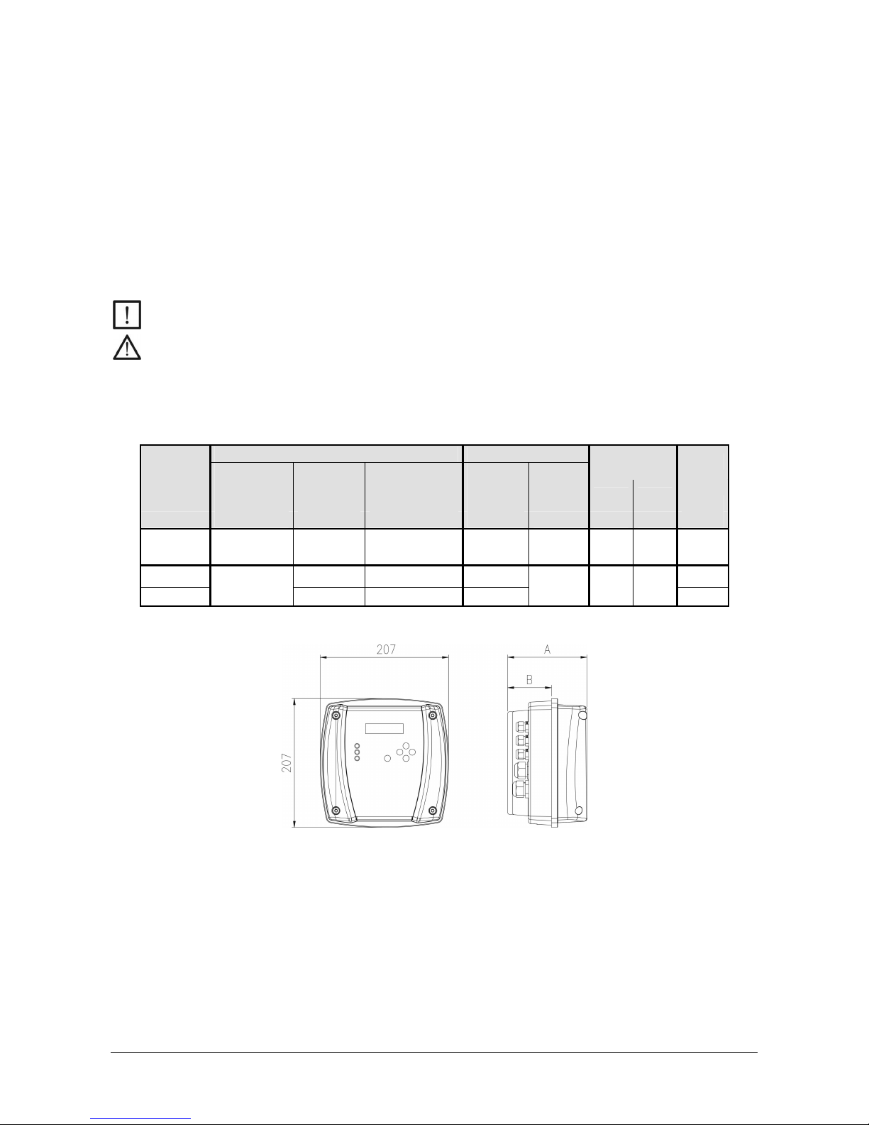
2.2) Dimensions.
2.2) Dimensions. 2.2) Dimensions.
2.2) Dimensions.
2.3) Features.
2.3) Features. 2.3) Features.
2.3) Features.
• Degree of protection: IP55.
• Maximum working ambient temperature: 40 ºC.
• Inputs: 1 analogue 4-20mA, with 24V DC power supply. 1 digital input for the level switch.
• Outputs: Only M..., 1 potential-free contact, maximum current 2A at 250V AC.
• Communications: RS 485 serial port.
- 4 -
3) INSTALLATION.
3) INSTALLATION.3) INSTALLATION.
3) INSTALLATION.
3.1) Hyd
3.1) Hyd3.1) Hyd
3.1) Hydraulic installation.
raulic installation. raulic installation.
raulic installation.
3.1.1) Installation layout.
123
4
1. Pump with Speedrive.
2. Non-return valve.
Not required others non-return valves in the delivery pipe.
3. Pressure transducer. The 4-20 mA, 10 bar type,
EMC according EN 61000-6-2.
4. Accumulator.
Its sole function is to compensate minor water losses in the installation, preventing
continuous pump start-ups and stops. The accumulator's volume must be at least 10% of the
nominal flow of the pump(s) installed, calculated in litres per minute. (For ex.: Multi35 5,
QMAX=100 [l/min]x0.1=10 accumulator
≥
10l) The preload pressure must be 1 bar below to
the rated pressure.
3.1.2) Hydraulic connections.
See the pump manual.
For facilities in negative suction, it is required that the pipes are primed completely.
3.2) Elect
3.2) Elect3.2) Elect
3.2) Electrical connection to the motor.
rical connection to the motor.rical connection to the motor.
rical connection to the motor.
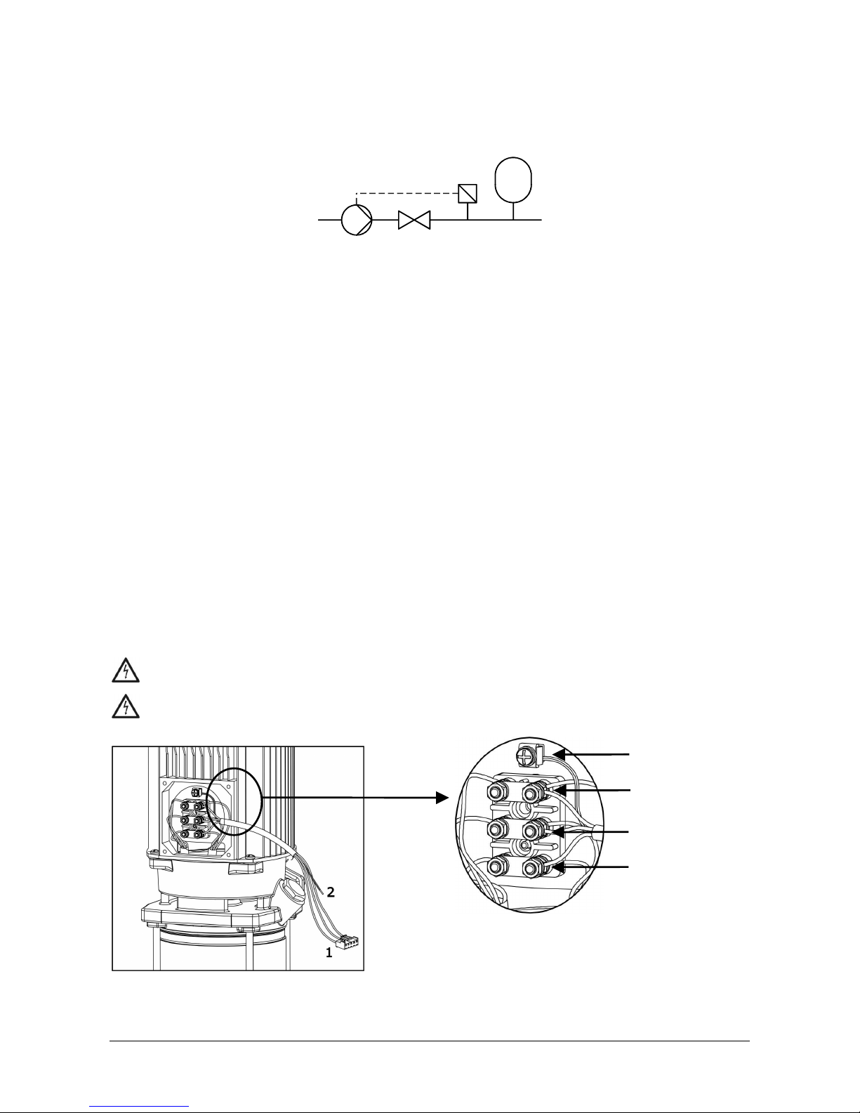
3.2.1) Speedrive with single
3.2.1) Speedrive with single3.2.1) Speedrive with single
3.2.1) Speedrive with single----phase input (Figure 1):
phase input (Figure 1):phase input (Figure 1):
phase input (Figure 1):
The motor must be connected to a 230 V power supply source.
The cable (1) supplied with the inverter must be connected to the motor.
If you wish to activate the 60Hz motor output, select the corresponding parameter in the menu.
Make sure that electrical consumption shown on the motor's data plate does not exceed that supplied by the
inverter.
DANGER.
Risk of electrocution
. Always connect the supplied grounding cable (2) between the motor
and inverter set.
DANGER.
Risk of electrocution
. Never open the Speedrive cover before disconnecting the power
supply during at least 5 minutes
least 5 minutesleast 5 minutes
least 5 minutes.
Figure 1
Figure 1Figure 1
Figure 1
Blue
Brown
Black
Yellow/Green
- 5 -
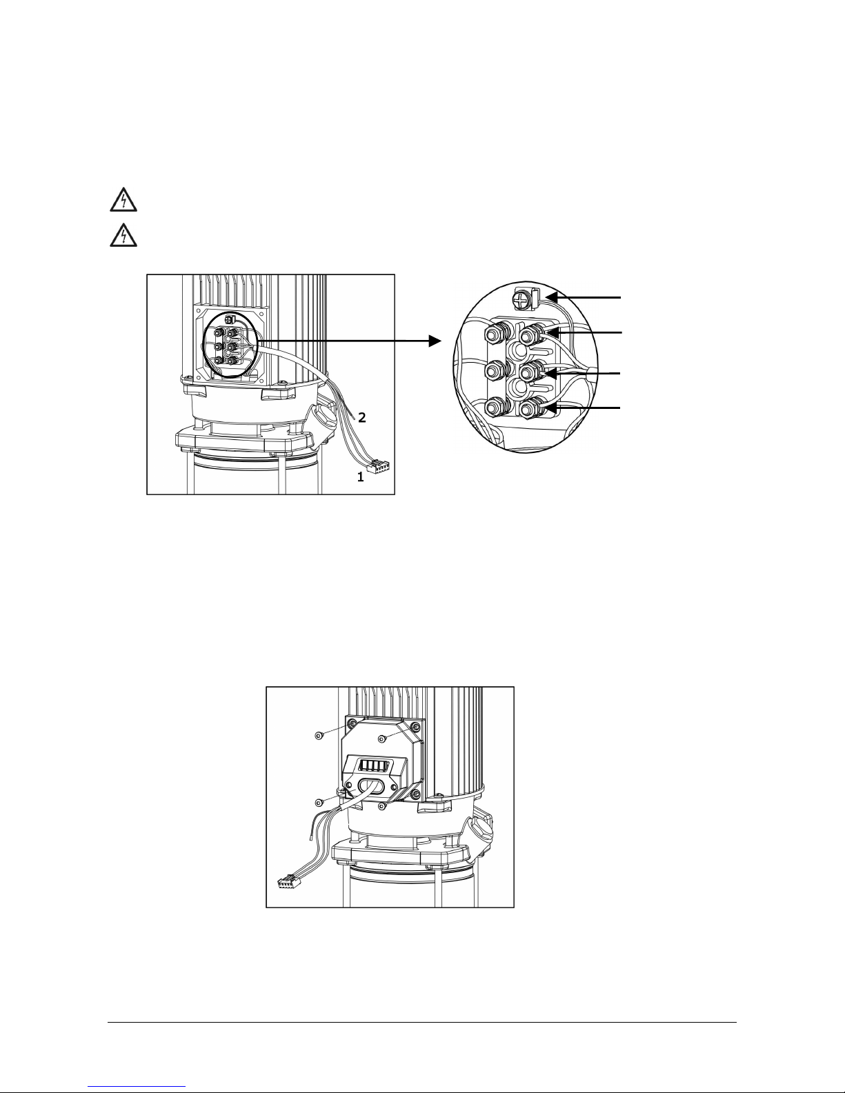
3.2.2) Speedrive with three
3.2.2) Speedrive with three3.2.2) Speedrive with three
3.2.2) Speedrive with three----phase input (Figure 2):
phase input (Figure 2):phase input (Figure 2):
phase input (Figure 2):
The motor must be connected to a 400 V power supply source.
The cable (1) supplied with the frequency inverter must be connected to the motor.
If you wish to activate the 60Hz motor output, select the corresponding parameter in the menu.
Make sure that electrical consumption shown on the motor's data plate does not exceed that supplied by the
inverter.
DANGER.
Risk of electrocution.
Always connect the supplied grounding cable (2) between the motor
and inverter set.
DANGER.
Risk of electrocution.
Never open the Speedrive cover before disconnecting the power
supply during at least 5 minutes
least 5 minutesleast 5 minutes
least 5 minutes.
Figure 2
Figure 2Figure 2
Figure 2
3.3) Installation on the pump.
3.3) Installation on the pump.3.3) Installation on the pump.
3.3) Installation on the pump.
The Speedrive is installed on the motor with a special supplied adapter.
The inverter is cooled with the use of the motor's cooling elements.
The unit has been designed for vertical and horizontal installation.
3.3.1) Motor adapter (Figure 3):
3.3.1) Motor adapter (Figure 3):3.3.1) Motor adapter (Figure 3):
3.3.1) Motor adapter (Figure 3):
Replace the connections box with the supplied motor adapter. Use the same screws. Torque 1~1.2 Nm.
Figure 3
Figure 3Figure 3
Figure 3
Azul
Marrón
Negro
Blue
Brown
Black
Yellow/Green
- 6 -
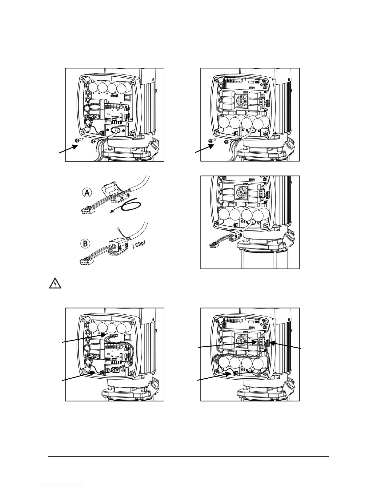
3.3.2) Speedriv
3.3.2) Speedriv3.3.2) Speedriv
3.3.2) Speedrive.
e.e.
e.
Installation of the Speedrive on the adapter. Use the screws (1) supplied.
Torque: 3 Nm.
Single
SingleSingle
Single----Phase Version
Phase VersionPhase Version
Phase Version Three
ThreeThree
Three----Phase Version
Phase VersionPhase Version
Phase Version
Prepare the motor wires with ferrites:
connect the grounding wire (2)
Connect the motor wires to the provided socket (3)
Single
SingleSingle
Single----Phase Version
Phase VersionPhase Version
Phase Version Three
ThreeThree
Three----Phase Version
Phase VersionPhase Version
Phase Version
Figure 4
Figure 4Figure 4
Figure 4
Figure 5
Figure 5Figure 5
Figure 5
1
1
3
2
2
3
4
- 7 -
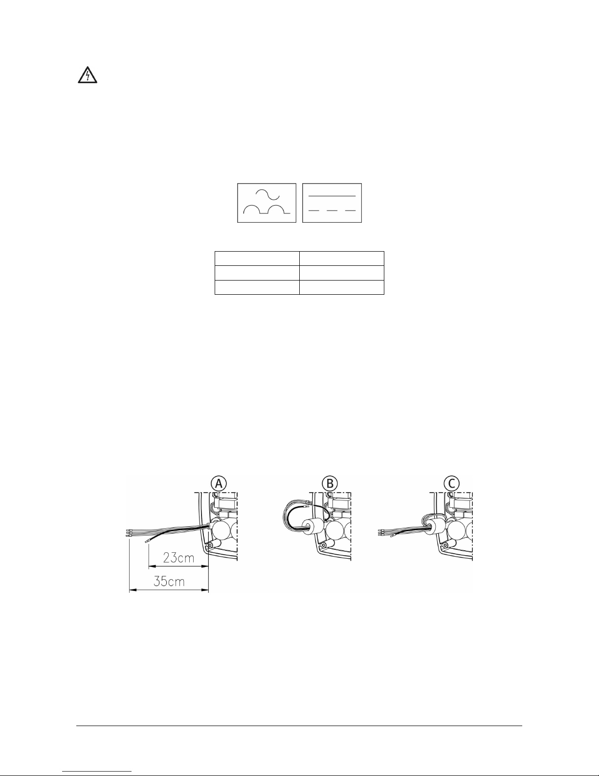
3.4) Power supply connection.
3.4) Power supply connection.3.4) Power supply connection.
3.4) Power supply connection.
DANGER. Risk of electrocution.
Connection and grounding are compulsory.
All electrical connections will be in accordance with the IEC-60364 Regulations (electrical installation
in buildings) or the regulations in force in the destination country and local regulations.
The power supply line of equipment must be adequately protected. These protection elements will
prevent damage to persons during an electrical leakage. An exclusive power supply line is
recommended.
The system protection will be based on an earth leakage switch (I∆n = 30 mA).
The recommended earth leakage switch is "class A"
"class A""class A"
"class A" for pulsed and continuous currents, marked with the
following symbols:
The earth leakage value will depend on the number of units connected to the line and their power.
Motor size
Motor sizeMotor size
Motor size Leakage current
Leakage currentLeakage current
Leakage current
0.75 to 3 kW < 3.5 mA
4 to 5.5 kW < 5 mA
The electrical installation should have a multiple separation system with contact openings ≥ 3 mm.
Single
SingleSingle
Single----phase frequency inverters.
phase frequency inverters.phase frequency inverters.
phase frequency inverters.
These units are supplied with a H07 RN-F power supply cable, 2m length and a connection plug. The power supply
input must be single-phase, at 230 V, 50 or 60 Hz.
See Figure 6
Figure 6Figure 6
Figure 6 for reference.
Voltage variations allowed ±10
Three
ThreeThree
Three----phase frequency inverters.
phase frequency inverters.phase frequency inverters.
phase frequency inverters.
These units have a three-phase power supply input, at 400 V, 50 or 60 Hz. The cabling procedures must be
undertaken by a professional installation entity.
Connection socket according figure 5
figure 5figure 5
figure 5 (4)
(4)(4)
(4). Connections, in accordance with Figure 7
Figure 7Figure 7
Figure 7.
Voltage variations allowed ±10%.
Preparing the power supply wires:
- 8 -
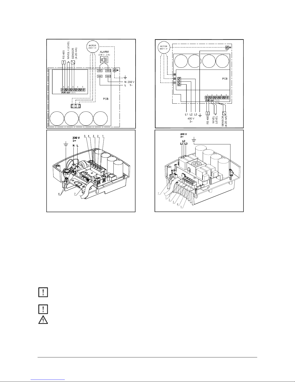
3.5) Signals wires connection.
3.5) Signals wires connection.3.5) Signals wires connection.
3.5) Signals wires connection.
Single
SingleSingle
Single----phase version
phase versionphase version
phase version
Three
ThreeThree
Three----Phase Version
Phase VersionPhase Version
Phase Version
Figure 6
Figure 6Figure 6
Figure 6
Figure 7
Figure 7Figure 7
Figure 7
1.- RS 485 communications output to connect various inverters. Up to 4 units.
2.- Auxiliary input for an external level switch or a potential-free contact to activate or stop the circuit.
Note: This input is supplied from the factory with an electric cable bridge.
3.- Input of the 4-20mA pressure transducer.
4.- Potential-free auxiliary input. Not used.
5.- Auxiliary transducer input. Not used.
6.- Only in single-phase versions. 230 V potential output, 2A maximum, external display or acoustic
operation for alarm signals.
7.- Micro-switches used to configure the inverter's operation.
WARNING: All external cabling connections must use terminal tips on the ends of each cable. External
cables must comply with the corresponding electrical safety and insulation regulations. Installation
should be made by qualified service personnel.
Avoid any cable pieces from falling inside the circuit, which could lead to its destruction.
DANGER. Risk of electrocution.
If the unit has to be uncovered due to any circumstance, first disconnect the power supply and wait 5
minutes before starting work with the circuit. The circuit's capacitors store energy. There is enough
energy inside the circuit to cause a strong electric discharge, even when the unit is not powered.
 Loading...