

Espa evopool SilenPlus Instruction Manual

ES Manual de instrucciones (instrucciones originales) ........ 3
EN Instruction manual (translation).................................... 9
FR Manuel d'instructions (traduction) ................................ 14
DE Gebrauchsanweisung (Übersetzung) ............................. 20
IT Manuale d'istruzioni (traduzione) ................................. 26
NL Handleiding (vertaling) ................................................. 32

2
3
MANUAL DE INSTRUCCIONES (ORIGINAL) ES
A
Atención a los límites de empleo.
I
Este aparato pueden utilizarlo niños con edad de 8 años
y superior y personas con capacidades físicas, sensoriales o mentales reducidas o falta de experiencia y
conocimiento, si se les ha dado la supervisión o formación apropiadas respecto al uso del aparato de una
manera segura y comprenden los peligros que implica.
Los niños no deben jugar con el aparato.
La limpieza y el mantenimiento a realizar por el usuario
no deben realizarlos los niños sin supervisión.
B
La tensión de la placa tiene que ser la misma que la
de la red.
C
Conecte el equipo a la red mediante un interruptor
omnipolar con una distancia de apertura de los contactos de, al menos, 3 mm.
D
Como protección suplementaria de las sacudidas
eléctricas letales, instale un interruptor diferencial
de elevada sensibilidad (0,03 A).
E
Efectúe la toma a tierra de la unidad.
F
Utilice la bomba en el campo de prestaciones indicado en la placa.
J
Atención a los líquidos y ambientes peligrosos.
G
Recuerde cebar la bomba.
K
Atención a las pérdidas accidentales.
No exponga la electrobomba a la intemperie.
H
Asegúrese que el motor pueda auto ventilarse.
L
Atención a la formación de hielo.
Desconectar de la corriente antes de cualquier
intervención de mantenimiento.
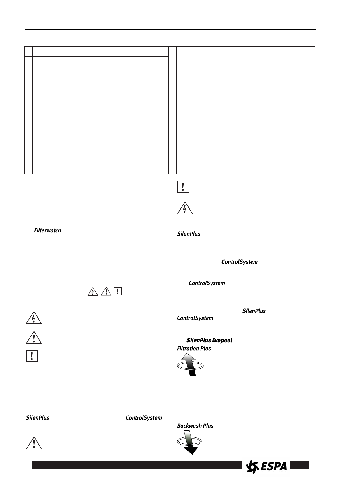
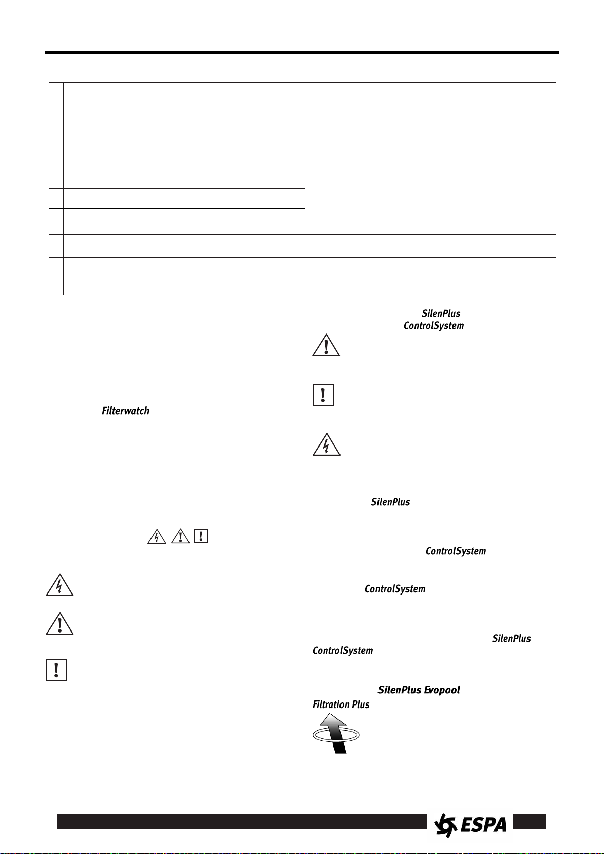
PELIGRO
riesgo de
electrocución
La no advertencia de esta
prescripción comporta un riesgo de electrocución.
PELIGRO
La no advertencia de esta
prescripción comporta un riesgo de daño a las personas o
cosas.
ATENCIÓN
La no advertencia de esta
prescripción comporta un riesgo de daños a la bomba o a la
instalación.
Instrucciones de seguridad y prevención de daños para las personas y equipos
Contenido
Advertencia para la seguridad de personas y cosas ....... 3
1. Generalidades .................................................... 3
2. Manipulación ....................................................... 4
3. Instalación .......................................................... 4
4. Puesta en marcha ............................................... 4
5. Funcionamiento .................................................. 5
6. Función ............................................. 5
7. Configuración avanzada ..................................... 6
8. Programador horario incorporado ...................... 6
9. Mantenimiento .................................................... 6
10. Declaración de conformidad ............................... 7
11. Indicadores LED ................................................. 8
12. Ilustraciones ...................................................... 38
Advertencia para la seguridad de personas y cosas
La siguiente simbología junto a un pá-
rrafo indican la posibilidad de peligro como
consecuencia de no respetar las prescripciones correspondientes.
1. GENERALIDADES
Este manual es complementario del manual de instalación de las bombas de piscina estándar.
Las instrucciones que facilitamos tienen por objeto la
correcta instalación y óptimo rendimiento de las
bombas para recirculación de agua en piscinas,
equipados con variador de frecuencia
sensor de posición de la válvula,
(Véase figura 8)
1.1 Descripción del producto
Las bombas equipan motor eléctrico estándar con variador de frecuencia integrado. Son para
conexión monofásica.
Disponen de emisor de radiofrecuencia para la comunicación con el
para control remoto mediante aplicaciones Smartphone.
El sensor
para la válvula multipuerto de 6 vías de un filtro de
piscinas estándar. Está equipado con sensores electrónicos para posicionamiento polar y control del
motor.
El funcionamiento conjunto de las bombas y
del permite el total control de las
funciones de la bomba con solo maniobrar la válvula
del filtro.
1.2 Funciones
incrementa la eficacia de la limpieza en superficie de la
piscina.
®
®
.
EFICACIA: los ciclos de trabajo específicamente desa-
y
rrollados para la aplicación en piscinas consiguen una
máxima eficacia.
Lea estas instrucciones antes de realizar la
instalación.
Guárdelas para futuras consultas.
El adecuado seguimiento de las instrucciones
de instalación y uso, así como de los esquemas de conexión eléctricos garantiza el buen
funcionamiento del equipo.
La omisión de las instrucciones de este manual puede derivar consecuencias de todo tipo,
acerca de las cuales declinamos cualquier
responsabilidad.
®
y de enlace Bluetooth®
®
es el detector de posición
®
:
Sistema que consigue una optimización
del filtrado para aumentar la eficiencia,
con el consiguiente ahorro de energía
eléctrica, a la vez que añade un ciclo que
4
ES
AHORRO: un mínimo del 80% de ahorro en energía
eléctrica respecto a las bombas estándar, con el consiguiente ahorro económico.
:
Sistema de contralavado que, gracias a un
ciclo desarrollado específicamente, consigue aumentar la eficacia del proceso a la
vez que acorta el tiempo de limpieza, reduciendo drásticamente la cantidad de agua consumida y consiguiendo un lavado eficaz.
EFICACIA: reducción del tiempo de contralavado y
aumento de la eficacia en la limpieza del filtro.
AHORRO: un mínimo del 25% de ahorro de agua
respecto a las bombas estándar.
La velocidad de rotación de la bomba se auto-adapta
a la normal y progresiva obstrucción del filtro para que
no disminuya la eficacia de la función .
2. MANIPULACIÓN
Se suministra en un embalaje adecuado para evitar
su deterioro durante el transporte. Antes de desembalar el producto revise que el envoltorio no haya
sufrido daños ni esté deformado.
Manipule el producto con cuidado y con las herramientas adecuadas.
3. INSTALACIÓN
Estos equipos están concebidos para su uso en interiores.
3.1. Instalación de la bomba.
ATENCIÓN: Siga las instrucciones del manual
de instalación de la bomba estándar.
3.2. Conexión eléctrica
La instalación eléctrica deberá disponer de un
sistema de separación múltiple con abertura de
contactos 3 mm.
La protección del sistema se basará en un interruptor diferencial (Δfn = 30 mA).
El equipo se suministra con cable de alimentación con
clavija.
No manipular el equipo.
3.3 Instalación del
Montar el en el mando de la válvula
multipuerto del filtro (Ver figura 1)
Seleccionar una ubicación lo más cerca posible del
centro de giro.
Limpiar la superficie con alcohol.
Levantar la protección de los adhesivos y clavar el
en el sitio elegido.
Atención a la posición del . La zona
de tornillo debe quedar cercana al eje de giro
Asegurar el montaje tensando la cinta por debajo
del mando. Comprobar que quede bien fijado
4. PUESTA EN MARCHA
4.1 Puesta en marcha del equipo.
Siga las instrucciones del manual de instalación de la
bomba para su correcta puesta en marcha.
4.2 Configuración inicial
En la primera puesta en marcha es necesario vincular
con (Ver figura 2)
ATENCIÓN Es muy importante respetar el
orden de las operaciones aquí descrito:
4.2.1 Puesta en marcha del
Conectar la bomba a la corriente.
El sistema se pondrá en marcha, un juego de luces
indica que se ha activado.
Si un no ha sido vinculado
anteriormente, la bomba no se pondrá en marcha.
queda a la espera de crear vinculo. Los 3
Leds parpadean conjuntamente.
4.2.2 Activación del
Para evitar que se agote la pila antes de la puesta en
marcha del equipo, el dispone de un
interruptor ON/OFF interno, que debe ser activado
(ver figura 2)
ATENCIÓN No acercar elementos magnéticos al
durante esta operación.
Evite que algún campo magnético pueda alterar
el buen funcionamiento del sistema.
CON LA BOMBA CONECTADA A LA CORRIENTE
(ver 4.2.1):
Asegúrese de que la válvula esté en la posición
intermedia entre 1 y 4.
Levantar la tapa aflojando el tornillo.
Activar el ControlSystem actuando sobre el
mini-interruptor, desplazándolo a posición "ON".
Al conectar la pila, emite un código
único para una vinculación sin interferencias. Un
parpadeo de los leds indica que la comunicación ha
sido correcta. El LED verde queda iluminado.
Volver a colocar la tapa y a fijar el tornillo. Par de
apriete: 0.2 Nm.
4.2.3 Calibración del
Las 6 posiciones de la válvula deben ser indicadas al
sistema. Para ello, seguir el siguiente proceso de
calibración (Ver figura 3):
Mover el mando hasta la posición 4. Esperar a que
el LED verde quede iluminado.
Mover el mando hasta la posición 6. Esperar a que
el LED verde quede iluminado.
Mover el mando hasta la posición 2. Esperar a que
el LED verde quede iluminado.
Mover el mando hasta la posición 5. Esperar a que
el LED verde quede iluminado.
Mover el mando hasta la posición 3. Esperar a que
el LED verde quede iluminado.
Mover el mando hasta la posición 1.
5
ES
La bomba se pondrá en marcha en modo
Remoto. Se encenderá el LED correspondiente.
4.3 Sistema múltiple
En una instalación con diversos equipos, la puesta en
marcha de la y la activación del
se deberá hacer de forma ordenada.
Cada equipo se vincula mediante un código único para
evitar interferencias entre ellos.
Una , en modo espera, se vinculará al primer
que se active.
ATENCIÓN, activar el de la válvula
correspondiente al equipo en espera.
4.4 En ausencia de
Si no dispone de o prefiere no usarlo, el
sistema puede funcionar, con las mismas prestaciones,
de forma manual.
Prescindir de las operaciones de activación y calibración
pasando a modo Manual después conectar la .
4.5 Cambio del
Si en un sistema ya vinculado es necesario sustituir el
, será necesario eliminar el número de
serie del antiguo antes de vincular el nuevo.
Para ello, con la bomba conectada a la corrien-
te, mantener pulsado el botón F durante 10 segundos.
Un parpadeo de leds indica que la operación se ha realizado con éxito.
El número de serie anterior quedará eliminado y el sistema entrará en modo "espera de vinculación". Proceder
como se indica en 4.2.2.
5. FUNCIONAMIENTO
5.1 Modo REMOTE
Es el modo de funcionamiento por defecto.
La bomba ejecuta la función más adecuada a la posición
de la válvula del filtro. (Ver figura 4).
En posición FILTRADO: función
En posición LAVADO: función
En posición CERRADO: bomba parada.
En alguna de las otras posiciones: la bomba funciona
al 100% de su potencia.
Al manipular el mando de la válvula, la bomba se
para automáticamente para facilitar el movimiento de
la válvula.
En cualquier posición intermedia, la bomba se man-
tiene parada.
Para cambiar de modo de funcionamiento, simplemente
mueva la válvula a la posición deseada.
Para evitar funcionamientos indeseados, la respuesta de la electrónica está retardada 1 segundo.
El parpadeo del LED rojo indica que la comunicación ha sido efectiva.
Mueva la válvula con suavidad.
ATENCIÓN la configuración de la válvula debe
responder a las 6 posiciones estándar según figura 4.
Para otras configuraciones de válvula, póngase en
contacto con su servicio técnico.
5.2 Modo MANUAL
Pulsado la tecla M, prescinde de la señal del
y se ejecuta en alguna de las funciones
preestablecidas:
Se enciende el led MAN.
La bomba se pone en marcha a una velocidad fija,
programable. De forma estándar es a 2300 RPM (40
Hz). Es el llamado Ciclo Mixto (MISC. CYCLE).
Al pulsar la tecla F se recorren, secuencialmente, las
diversas funciones de la .
Entre cada función, la bomba se detiene para permitir
el movimiento de la válvula u otras operaciones.
La secuencia es:
1. Ciclo mixto (MISC. CYCLE).
2. Stop.
3. .
4. Stop.
5. .
6. Stop.
7. Ciclo mixto...
La iluminación de los leds indica la función seleccionada en cada momento
Al volver a pulsar M se sale del modo Manual para
volver a Remote.
5.3 Fallo por falta de agua y reintentos.
En modo se monitoriza regularmente el
sistema para verificar que la bomba no funcione sin
agua.
Si detecta que la bomba funciona sin agua,
detiene el motor.
El sistema intentará arrancar de nuevo al cabo de 1',
5', 15' y 1 hora (Fig. 5). Si los reintentos no tienen
éxito quedará en fallo permanente.
Una secuencia de leds indica el estado del fallo. (Ver
apartado 7)
Para interrumpir el ciclo de reintentos o para reiniciar
del fallo permanente, pulsar la tecla F.
5.4 Estado del sistema
Espa pone a disposición de instaladores y usuarios la
aplicación para monitorización del estado
del sistema e interacción con .
Se debe disponer de un Smartphone con conectividad Bluetooth y tener instalada la aplicación
, disponible en www.espa.com así
como en PlayStore o AppStore.
El cambio a modos Manual/Remote y todas sus funciones son posibles mediante esta aplicación.
6. FUNCIÓN
6.1 Activación.
La activación de solo debe hacerse después de las labores de mantenimiento iniciales,
asegurándose de que el filtro está totalmente limpio.
6
ES
Para activar
- Pulse "M" durante 5 segundos.
- El LED " " parpadeará 3 veces.
En el momento su activación, iniciará un
periodo de aprendizaje de 3 minutos, durante los cuales la bomba funcionará al 100%. No se debe
interrumpir este proceso.
La correcta activación de la función se indica
mediante un parpadeo lento del LED
6.2 Auto-adaptación.
Con la función activada, el funcionamiento
de la bomba, durante la fase , se acomodará al grado de colmatación del filtro.
Es normal notar un progresivo aumento en la velocidad de rotación de la bomba.
6.3 Aviso saturación filtro.
Cuando el sistema detecte que ha llegado al nivel de
saturación, la bomba reclamará que se efectúe un
ciclo de limpieza del filtro.
- El LED parpadeará rápidamente.
- Si dispone de la aplicación , al conectar
con la bomba recibirá el aviso correspondiente.
Después de la limpieza de filtro, los avisos desaparecerán y el sistema volverá al estado normal.
6.3 Desactivación.
Para desactivar
- Pulse "M" durante 5 segundos.
- El LED " " parpadeará 3 veces.
La función queda desactivada y el LED
deja de parpadear.
6.4 Control del sistema.
La activación y desactivación de , así
como el control del estado del sistema, se puede
efectuar mediante la aplicación
7. CONFIGURACIÓN AVANZADA
Se pueden configurar las distintas velocidades para
ajustar las funciones a las características de la instalación.
Se configurará la función que se esté ejecutando.
Para configurar una función, seleccionarla previamen-
te, ya sea en Manual o en Remoto, y pulsar
simultáneamente M+F durante 5 segundos.
Todas las velocidades de la función seleccionada se
reinician a ajustes de fábrica [= af]
Para aumentar o disminuir la velocidad pulsar M o F:
M = + 58 RPM (+ 1 Hz)
F = - 58 RPM (- 1 Hz)
Configuración de .
Se configura la velocidad de filtración.
· Mínimo = 1600 RPM (20 Hz), [= af]
· Máximo = 2900 RPM (50 Hz)
Configuración de .
Se configuran las velocidades máxima y mínima
manteniendo siempre un diferencial de 20 Hz entre
ellas
· Mínimo = 1600/2320 RPM (20/40 Hz), [= af]
· Máximo = 1740/2900 RPM (30/50 Hz)
Configuración de Ciclo Mixto (sólo Manual)
El ajuste de fábrica es de 2320 RPM (40 Hz)
· Mínimo = 1600 RPM (20 Hz)
· Máximo = 2900 RPM (50 Hz)
Si no se pulsan M o F durante 5 segundos se guardan
los valores cambiados y se desactiva el modo configuración.
Toda la configuración de se puede
efectuar, también, mediante la aplicación
8. PROGRAMADOR HORARIO INCORPORADO
La bomba dispone de un reloj interno que
puede hacer la función de programador horario de
arranque y paro, substituyendo la necesidad de programación externa.
Con esta función, puede funcionar de forma
totalmente autónoma.
ATENCIÓN: la programación y mantenimiento
del programador horario sólo es posible a través de la aplicación .
8.1 Activación del programador horario.
PELIGRO. Riesgo de electrocución.
Nunca abrir la tapa de sin haber
desconectado el suministro eléctrico durante,
por lo menos, 5 minutos.
Levantar la tapa del aflojando los 4 torni-
llos. (Ver figura 5)
Activar el Timer actuando sobre el mini-interruptor,
desplazándolo a posición "ON".
Volver a colocar la tapa y a fijar los 4 tornillos. Par
de apriete: 0.5 Nm.
8.2 Programación horaria.
Vincular con el dispositivo externo mediante
Bluetooth siguiendo las indicaciones del dispositivo.
Ejecutar la aplicación y seguir sus indicaciones.
9. MANTENIMIENTO
Si no se comunica con
puede ser necesario substituir la batería.
Proceder como en apartado 4.2.
La batería es del tipo CR2450, de 1,5V.
Nuestros equipos están exentos de mantenimiento.

7
ES
Limpiar el equipo con un paño húmedo y sin utilizar
productos agresivos.
En épocas de heladas tenga la precaución de
vaciar las tuberías.
Si la inactividad del equipo va a ser prolongada
se recomienda desmontarlo y guardarlo en un
lugar seco y ventilado.
ATENClÓN: en caso de avería, la manipulación
del equipo sólo puede ser efectuada por un
servicio técnico autorizado.
La Relación de Servicios Técnicos Oficiales se encuentra en www.espa.com.
Llegado el momento de desechar el producto, este no
contiene ningún material tóxico ni contaminante. Los
componentes principales están debidamente identificados para poder proceder a un desguace selectivo.
10. DECLARACIÓN DE CONFORMIDAD
Declaramos, bajo nuestra responsabilidad, que los
productos de este manual cumplen con las siguientes
directivas comunitarias y normas técnicas:
- Directiva 2004/108/CE (CEM)
· Normas EN 61000-6-1 y EN 61000-6-3
- Directiva 2006/95/CE (Baja Tensión)
· Norma EN 60730-1 y EN 60730-2-6
Pere Tubert (Technical Manager)
ESPA 2025, SL
Ctra. de Mieres, s/n – 17820 Banyoles
Girona - Spain
8
ES
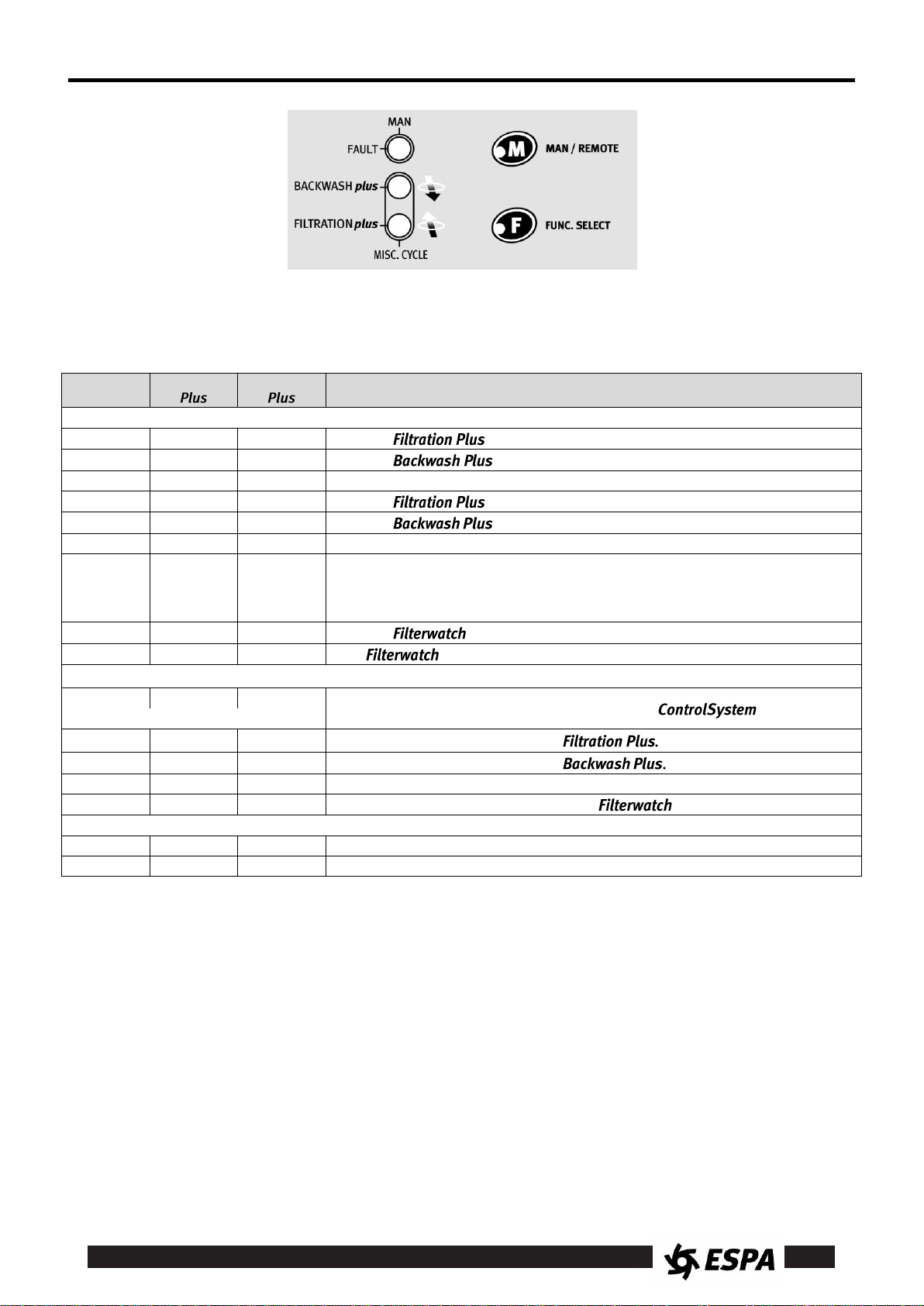
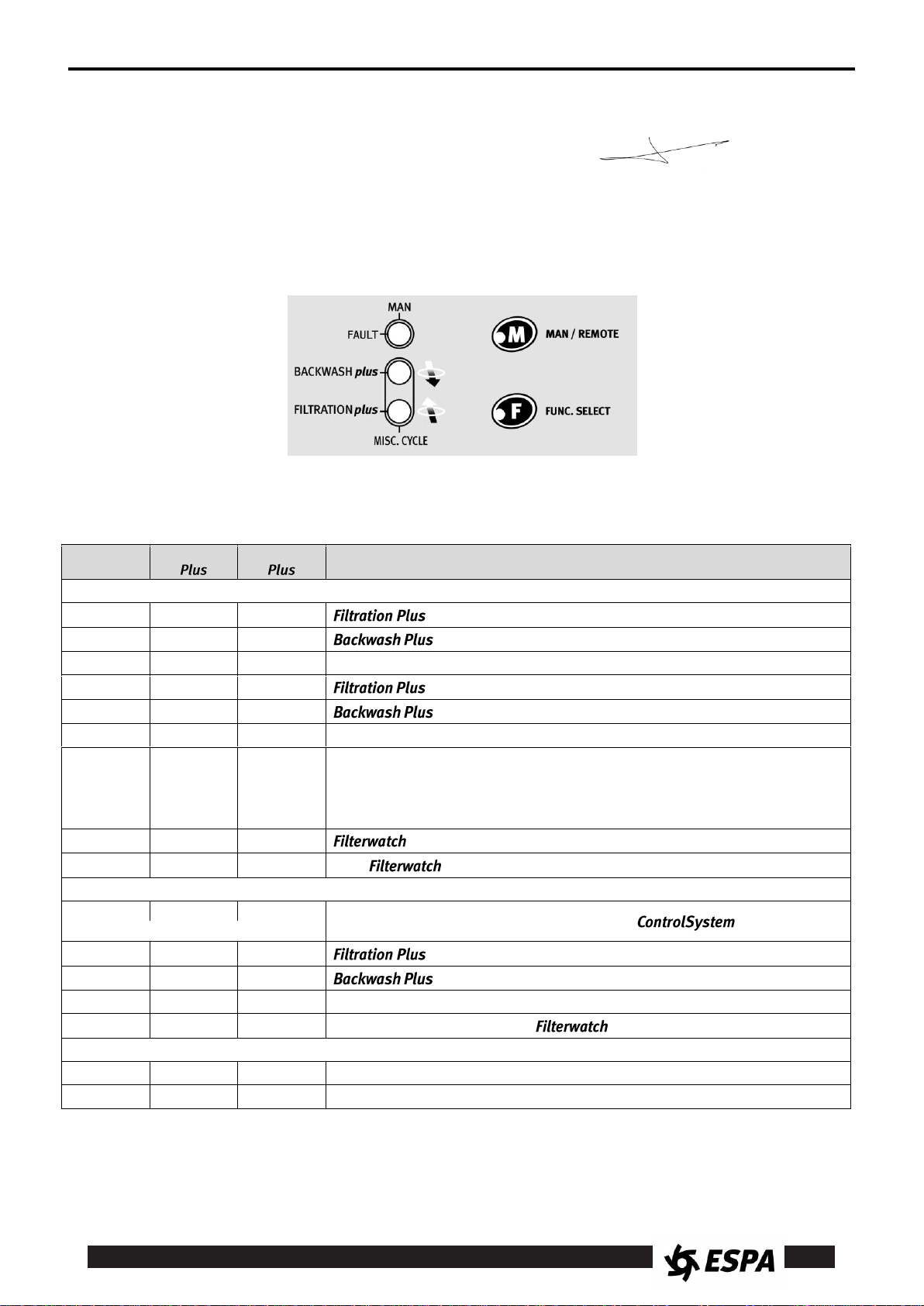
MAN/
FAULT
BACKWASH
FILTRATION
Estado del equipo
Funciones
0 0 1
Función en modo Remote.
0 1 0
Función en modo Remote.
0 1 1
Función Ciclo Mixto en modo Remote. Motor al 100%.
1 0 1
Función en modo Manual.
1 1 0
Función en modo Manual.
1 1 1
Función Ciclo Mixto en modo Manual.
2 0 0
Modo "en espera". Equipo en tensión, motor parado.
a) Válvula en posiciones intermedias o en posición 6 en modo Remote.
b) Función Stop en modo Manual.
c) Posición OFF del Timer.
0 0 2
Función activa.
0 3 2
Con activa: Filtro saturado, proceda a limpiarlo.
Configuración
3 3 3
Configuración inicial: en espera de vínculo con
(...conjuntamente...)
3 0 1
Configuración de la velocidad de
3 1 0
Configuración de la velocidad de
3 1 1
Configuración de la velocidad de Ciclo Mixto.
0
0
3 (3 veces)
Activación/desactivación de la función
Errores
2 1 2
Error por falta de agua. Se reintenta el arranque.
2 1 1
Error falta de agua. Paro definitivo.
10. INDICADORES LEDs
Las posibles combinaciones de LEDs y su significado son:
0 = Led OFF
1 = Led ON
2 = Led intermitente lento
3 = Led intermitente rápido (flash)
9
INSTRUCTION MANUAL (Translation from the original Spanish) EN
A
Warning! Observe limitations of use.
I
This apparatus may be used by children 8 years or
older and persons with reduced physical, sensory or
mental capacities, or lacking experience and
knowledge, if they are supervised or receive adequate training on the safe use of the apparatus and
understand the dangers.
Children should not be allowed to play with the apparatus.
Children should not perform the ordinary cleaning
and maintenance tasks without supervision.
B
The name plate voltage must be the same as the
mains voltage.
C
Connect the unit to the mains via an omnipolar
switch with at least a 3 mm opening between contacts.
D
Install a high-sensitivity differential switch (0.03 A)
as extra protection against lethal electric shocks.
E
Connect the unit to the ground.
F
Use unit only within performance limits indicated on
the name plate.
J
Be careful with hazardous liquids and environments.
G
Remember to prime pump.
K
Caution! Look out for accidental leaks.
Do not expose pump to bad weather.
H
Check for motor self-ventilation.
L
Caution! Avoid icing.
Cut out power supply before servicing pump.
DANGER
electrocution risk
Not following this instruction
leads to a risk of electrocution.
DANGER
Not following this instruction
leads to a risk of injury to
people or damage to property.
WARNING
Not following this instruction
leads to a risk of damage to
the pump or the installation.
Safety instructions for preventing injury and damage to people and property
Contents
Warning for the safety of people and property ........ 9
1. General points .................................................... 9
2. Handling ............................................................ 10
3. Installation ........................................................ 10
4. Start-up ............................................................. 10
5. Operation .......................................................... 11
6. function ........................................... 11
7. Advanced configuration .................................... 12
8. Built-in timer ...................................................... 12
9. Maintenance ..................................................... 12
10. Declaration of compliance ................................ 13
11. LED indicators .................................................. 13
12. Illustrations ........................................................ 38
Warning for the safety of people and property
The following symbol beside a para-
graph indicates the possibility of danger as a result of
not following the corresponding instructions.
1. GENERAL POINTS
This manual is complementary to the standard installation manual for the swimming pool pumps.
The instructions we provide are intended to ensure the
proper installation and optimum performance of
swimming pool water circulation pumps equipped with
®
frequency inverter and
valve position sensor.
Read these instructions before installing.
Keep them for future reference.
(See figure 8)
1.1 Product description
a built-in frequency inverter. They are designed for a
single phase connection.
They have a radio-frequency transmitter to communicate with the
connection for remote control using smartphone applications.
The
a standard swimming pool filter 6-way multiport valve.
It is equipped with electronic sensors for polar positioning and to control the motor.
The joint working of pumps and the
functions just by operating the filter valve.
1.2
face cleaning.
EFFECTIVENESS: work cycles specially developed
for use in pools achieve maximum effectiveness.
SAVINGS: a minimum of 80% electricity savings over
®
standard pumps, with the resulting cost savings.
Following the installation and usage instructions
and the electrical connection diagrams correctly
ensures that the equipment will work properly.
Ignoring any of the instructions in this manual
can lead to all kinds of consequences for which
we accept no responsibility.
pumps equip a standard electric motor with
®
and a Bluetooth®
®
sensor is the position detector for
enables full control of the pump
®
functions
:
System which achieves filtration optimisation to increase efficiency, with the resulting electricity saving, while adding a cycle
to increase the effectiveness of pool sur-
:
Backwash system which, thanks to a specially developed cycle, increases process
efficiency while shortening cleaning time,

10
EN
drastically reducing the amount of water used for efficient cleaning.
EFFECTIVENESS: reduction of backwash time and
improved filter-cleaning efficiency.
SAVINGS: a minimum of 25% water savings over
standard pumps.
:
The rotational speed of the pump automatically adapts
to the normal and progressive clogging of the filter so
as not to reduce the effectiveness of the
function.
2. HANDLING
It is supplied in suitable packaging to prevent it deteriorating during transport. Before unpacking the product,
check that the packaging has not suffered damage or
is misshapen.
Handle the product carefully, with the right tools.
3. INSTALLATION
This equipment is designed for use indoors.
3.1. Pump installation.
WARNING: Follow the installation manual instructions for the standard pump.
3.2. Electrical connection
The electrical installation must have a multiple
separation system with a 3 mm contact opening.
The system’s protection will be based on a dif-
ferential switch (Δfn = 30 mA).
The equipment is supplied with a power cable with plug.
Do not manipulate the equipment.
3.3 installation
Fit the to the multiport filter valve control. (See figure 1)
Select a location as near as possible to the turning
centre.
Clean the surface with alcohol.
Lift the protective stickers and plug the
into the chosen place.
Watch the " " position. Screw area
should be closer to the rotation axis.
Secure the assembly by tightening the tape under
the control. Check that it is fixed properly.
4. START-UP
4.1 Starting up the equipment.
Follow the installation manual instructions for the
pump to start it up properly.
4.2. Initial configuration
The first time you start it up you need to link
with (See figure 2)
WARNING: It is very important to follow the order of the operations described here:
4.2.1 Starting up the
Connect the pump to the power supply.
The system will start up and a set of lights indicates
that it has been activated.
If a has not already been linked to it,
the pump will not start up.
is on standby waiting for the link to be estab-
lished. The 3 leds flash together.
4.2.2 Activating the
To prevent the battery running out before the equipment is started up, the ControlSystem has an internal
ON/OFF switch that must be activated (See figure 2)
CAUTION: Do not approach magnetic elements
to during this operation.
Ensure that no magnetic fields can affect the
proper operation of the system.
WITH THE PUMP CONNECTED TO THE
ELECTRICAL CURRENT (see 4.2.1):
Make sure the valve is in the intermediate position
between 1 and 4
Lift the cover, loosening the screw.
Activate the by moving the mini-
switch to the "ON” position.
When the battery is connected, transmits a unique code for an interference-free link.
Flashing leds indicate that proper communication has
been achieved. The green LED will light.
Replace the cover and fix it with the screw.
Torque: 0.2 Nm.
4.2.3 Calibrating the
The 6 valve positions must be indicated to the system.
For this purpose, use the following calibration process
(See Figure 3):
Move the valve control to position 4. Wait for the
green LED is illuminated.
Move the valve control to position 6. Wait for the
green LED is illuminated.
Move the valve control to position 2. Wait for the
green LED is illuminated.
Move the valve control to position 5. Wait for the
green LED is illuminated.
Move the valve control to position 3. Wait for the
green LED is illuminated.
Move the valve control to position 1.
The pump will start up in Remote mode.
The corresponding LED will come on.
4.3 Multiple system
In an installation with several pieces of equipment,
must be started up and the
activated in order.
Each piece of equipment is linked using a unique code
to prevent interference between them.
A pump in standby mode will be linked to the
first activated.
WARNING: activate the of the
valve for the pump on standby.
11
EN
4.4 In the absence of
If you do not have or prefer not to use it,
the system can work just as well manually.
Ignore the activation and calibration operations, switch
to Manual mode and then connect the .
4.5 Changing the
If it is necessary to replace the in a
system that is already linked, you will need to delete
the old serial number before linking the new one.
To do this, with the pump connected to the
power supply, keep the F button pressed down for 10
seconds. Flashing leds indicate that the operation has
been carried out correctly.
The previous serial number will be deleted and the
system will go into “link standby” mode. Proceed as
indicated in 4.2.2.
5. OPERATION
5.1 REMOTE mode
This is the default operating mode.
The pump carries out the most appropriate function con-
sidering the position of the filter valve. (See figure 3)
In FILTRATION position: function
In BACKWASH position: function
In CLOSED position: pump stopped.
In any of the other positions: the pump operates at
100% power.
When you operate the valve control, the pump
stops automatically to make the valve movement
easier.
In any intermediate position, the pump remains
stopped.
To change the working mode, simply move the valve
to the desired position.
To prevent accidental operation, the electronic
response is delayed by 1 second. The flashing
red LED indicates that proper communication
has been achieved.
Move the valve gently.
WARNING: the valve configuration must corre-
spond to the 6 standard positions, according to
figure 3.
For other valve configurations, contact your technical
service.
5.2 MANUAL mode
When you press the M key, ignores the
signal and runs one of the pre-set functions:
The MAN LED comes on.
The pump starts up at a fixed, programmable speed.
The standard setting is 2,300 RPM (40 Hz). This is
what is known as the MIXED CYCLE (MISC. CYCLE).
If you press the F key, it runs through the various
functions in sequence.
Between each function, the pump stops to allow valve
movement or other operations.
The sequence is:
1. Mixed cycle (MISC. CYCLE).
2. Stop.
3. .
4. Stop.
5. .
6. Stop.
7. Mixed cycle...
The lit leds indicates the function selected at all times.
When you press the M button again, you leave Manu-
al mode to go back to Remote.
5.3 No water fault and retries.
In mode, the system is regularly monitored to check that the pump is not operating without
water.
If detects the pump is working without water
it stops the motor.
The system will attempt to start up again after 1', 5',
15' and 1 hour (Fig. 4). If the retries fail, will
remain in permanent fault mode.
An LED sequence indicates the fault status. (See figure 7)
To interrupt the retry cycle or to restart from permanent fault mode, press the F key.
5.4 System status
Espa offers installers and users the application for monitoring the system status and
interacting with .
They must have a Smartphone with Bluetooth
connectivity and install the application
available in www.espa.com and in
PlayStore or AppStore.
With this app, it is possible to switch between Manu-
al/Remote modes and use all functions.
6. FUNCTION
6.1 Activation.
should only be activated after carrying out
the initial maintenance work, making sure that the filter
is completely clean.
To activate
- Press "M" for 5 seconds.
- The " " LED will blink 3 times.
When it is activated, will begin a 3 minute
learning period during which the pump will operate at
100%. Do not interrupt this process.
The correct activation of the function is
indicated by the LED blinking slowly
6.2 Auto-adaptation.
With activated, the pump operation during
the phase will adjust itself to the degree
of clogging of the filter.
It is normal to note a gradual increase in the rotational
speed of the pump.
12
EN
6.3 Filter saturation warning.
When the system detects that it has reached its saturation level, the pump will request that a filter cleaning
cycle be run.
- The LED will blink quickly.
- If you have the application, you will receive the corresponding warning when the pump is
connected.
After cleaning the filter, the warnings will disappear
and the system will return to its normal status.
6.3 Deactivation.
To deactivate
- Press "M" for 5 seconds.
- The " " LED will blink 3 times.
The function will be deactivated and the
LED will stop blinking.
6.4 System control.
You can activate and deactivate and
control the system status through the
application.
7. ADVANCED CONFIGURATION
Different speeds can be set to adjust the functions to
the characteristics of the installation.
The function being run will be configured.
To configure a function, first select it, either in Manual
or Remote mode, and at the same time press M + F
for 5 seconds.
All the speeds of the selected function will return to
the factory settings [= fs]
To increase or decrease the speed, press M or F:
M = + 58 RPM (+ 1 Hz)
F = - 58 RPM (- 1 Hz)
Configuring .
The filtration speed is set.
· Minimum = 1,600 RPM (20 Hz), [= fs]
· Maximum = 2,900 RPM (50 Hz), [= fs]
Configuring .
The maximum and minimum speeds are set, always maintaining a differential of 20 Hz between
them
· Minimum = 1,600/2,320 RPM (20/40 Hz), [= fs]
· Maximum = 1,740/2,900 RPM (30/50 Hz)
Configuring the Mixed Cycle (Manual only)
The factory setting is 2,320 RPM (40 Hz)
· Minimum = 1,600 RPM (20 Hz)
· Maximum = 2,900 RPM (50 Hz), [= fs]
If M and F are not pressed for 5 seconds the new values are stored and the configuration mode is
deactivated.
can also be entirely configured using
the application.
8. BUILT-IN TIMER
The pump has an internal clock that can
operate as a start and stop timer, making external
programming unnecessary.
With this function, can operate entirely independently.
ATTENTION: the programming and maintenance of the timer is only possible through the
app.
8.1 Activating the timer.
DANGER. Electrocution risk.
Never open the cover without turning
the power supply off at least 5 minutes beforehand.
Lift the cover by loosening the 4 screws.
(See figure 5)
Activate the Timer using the mini-switch, moving it
to the “ON” position.
Replace the cover and fix it with the 4 screws.
Torque: 0.5 Nm.
8.2. Time setting.
Link with the external device using Bluetooth,
following the instructions on the device.
Run the app and follow its indications.
9. MAINTENANCE
:
If is not communicating with it
may be necessary to replace the battery.
Proceed as in section 4.2.
It is a 1.5 V, CR2450 type battery.
:
Our equipment is maintenance free.
Clean the equipment with a damp cloth and without
using aggressive products.
In freezing weather, take the precaution of emptying the pipes.
If the equipment is going to be inactive for a
long time, you are recommended to dismantle it
and keep it in a dry, well-ventilated place.
WARNING: in case of a breakdown, the equipment must only be touched by an authorised
service technician.
The list of official technical services can be found at
www.espa.com.
When the time comes to throw the product away, it
does not contain any toxic or polluting material. The
main components are duly identified so you can dispose of them selectively.
13
EN
MAN/
FAULT
BACKWASH
FILTRATION
Equipment status
Functions
0 0 1
function in Remote mode.
0 1 0
function in Remote mode.
0 1 1
Mixed Cycle function in Remote mode. Motor at 100%.
1 0 1
function in Manual mode.
1 1 0
function in Manual mode.
1 1 1
Mixed Cycle function in Manual mode.
2 0 0
“Standby" mode. The equipment has power, motor stopped.
a) Valve in intermediate positions or position 6 in Remote mode.
b) Stop function in Manual mode.
c) Timer OFF position.
0 0 2
function active.
0 3 2
With active: Filter saturated, please clean it.
Configuration
3 3 3
Initial configuration: standing by for link with
(...together...)
3 0 1
speed setting.
3 1 0
speed setting.
3 1 1
Mixed Cycle speed setting.
0
0
3 (3 times)
Activation/deactivation of the function
Errors
2 1 2
No water error. Start-up retry attempted.
2 1 1
No water error. Full shut-down.
10. DECLARATION OF COMPLIANCE
We declare, under our own responsibility, that the
products in this manual meet the following Community
directives and technical regulations:
- Directive 2004/108/EC (EMC)
· Regulations EN 61000-6-1 and EN 61000-6-3
- Directive 2006/95/EC (Low Voltage)
· Regulation EN 60730-1 and EN 60730-2-6
11. LED INDICATORS
The possible LED combinations and their meanings are:
0 = LED OFF
1 = LED ON
2 = LED flashing slowly
3 = LED flashing quickly
Signed:
Pere Tubert (Technical Manager)
ESPA 2025, SL
Ctra.de Mieres, s/n – 17820 Banyoles
Girona - Spain
14
MANUEL D’INSTRUCTIONS (Traduction de l'original en espagnol) FR
A
Attention aux limitations d’utilisation.
I
Cet appareil peut être utilisé par des enfants de 8
ans et plus, ainsi que des personnes aux capacités
physiques, sensorielles ou mentales réduites, ou
qui manquent d'expérience et de connaissance,
dès lors que ces personnes sont supervisées lors
de l'usage de l'appareil ou qu'elles ont reçu la formation adéquate pour une utilisation sécurisée et
qu'elles comprennent les risques existants.
Les enfants ne doivent pas jouer avec l'appareil.
Les tâches de nettoyage et d'entretien que l'utilisateur doit effectuer ne doivent pas être réalisées par
des enfants sans surveillance
B
La tension indiquée sur la plaque doit être identique
à celle du secteur.
C
Connecter le groupe au secteur par l’intermédiaire
d’un interrupteur omnipolaire avec une distance
d’ouverture des contacts d’au moins 3 mm.
D
Comme protection supplémentaire contre les décharges électriques mortelles, installer un
interrupteur différentiel à haute sensibilité (0,03 A).
E
Effectuer la mise à la terre du groupe.
F
Utiliser le groupe en respectant les limites de performances indiquées sur la plaque.
J
Attention aux liquides et aux milieux dangereux.
G
Ne pas oublier d’amorcer la pompe.
K
Attention aux fuites accidentelles.
Ne pas exposer la pompe aux intempéries.
H
Contrôler que le moteur peut s’auto ventiler.
L
Attention à la formation de glace.
Couper l’alimentation électrique de l’électropompe
avant toute intervention d’entretien.
DANGER
Risque
d'électrocution
Si cet avertissement n'est
pas pris en compte, il existe
un risque d'électrocution.
DANGER
Si cet avertissement n'est
pas pris en compte, il existe
un risque de dommages aux
personnes et aux biens.
ATTENTION
Si cet avertissement n'est
pas pris en compte, il existe
un risque de dommages sur
la pompe ou l'installation.
Consignes de sécurité et prévention des dommages aux personnes et aux appareils
(Se reporter à la figure 8)
Table des matières
Avertissements relatifs à la sécurité des per-
sonnes et des biens ................................................ 14
1. Généralités ....................................................... 14
2. Manipulation ..................................................... 15
3. Installation ......................................................... 15
4. Mise en marche ................................................ 15
5. Fonctionnement ................................................ 16
6. Fonction .......................................... 17
7. Configuration avancée ...................................... 17
8. Programmateur horaire intégré ........................ 17
9. Maintenance ..................................................... 18
10. Déclaration de conformité ................................. 18
11. Voyants LED ..................................................... 19
12. Illustrations ........................................................ 38
Avertissements relatifs à la sécurité des personnes et des biens
Le symbole suivant devant un paragraphe indique l'existence d'un risque lié au nonrespect des prescriptions correspondantes.
1. GÉNÉRALITÉS
Ce manuel complète le manuel d'installation des pompes
de piscine standard.
Les instructions que nous fournissons visent à garantir la
bonne installation et le rendement optimal dans les
piscines des pompes de filtration d'eau équipées d'un
variateur de fréquence
position de la vanne,
®
et d'un capteur de
®
.
Lisez attentivement ces instructions avant de procéder à l'installation.
Conservez-les pour pouvoir vous y reporter ultérieurement.
Suivre attentivement les instructions d'installation
et d'utilisation ainsi que les schémas de branchement électrique permet de garantir le bon
fonctionnement de l'équipement.
Ne pas tenir compte des instructions de ce manuel pourrait provoquer des conséquences de tout
genre, pour lesquelles nous déclinons toute responsabilité.
1.1 Description du produit
Les pompes sont équipées d'un moteur électrique standard intégrant un variateur de fréquence. Leur
alimentation est de type monophasé.
Elles sont munies d'un émetteur à radiofréquence pour la
communication avec le
®
et de liaison
Bluetooth® pour la commande à distance depuis des
applications pour Smartphone.
Le capteur
®
est le détecteur de position
pour la vanne multiport à 6 voies d'un filtre de piscine
standard. Il est équipé de capteurs électroniques pour le
positionnement polaire et la commande du moteur.
Le fonctionnement conjoint des pompes et du
permet de contrôler toutes les fonctions de
la pompe en manœuvrant simplement la vanne du filtre.
1.2 Fonctions
®
:
Système d'optimisation du filtrage. Il permet
d'augmenter l'efficacité de la pompe et de
faire des économies d'énergie électrique,
tout en ajoutant un cycle qui augmente l'ef-
ficacité du nettoyage en surface de la piscine.
EFFICACITÉ: les cycles de travail spécialement conçus
pour l'application sur des piscines garantissent une effi-
 Loading...