


SPIRAL MIXER WITH REMOVABLE BOWL
PETRIN A SPIRALE A CUVE FIXE
IMPASTATRICE A SPIRALE A VASCA ESTRAIBILE
SPI 160-300 A
HYBRID
INSTRUCTION FOR USE AND MAINTENANCE
NOTICE D’UTILISATION ET DE MAINTENANCE
ISTRUZIONI USO E MANUTENZIONE
Code/codice N° 876577 rev. 02
February/Février/Febbraio 2014

CAREFULLY READ THIS INSTRUCTION
MANUAL BEFORE OPERATING THE MACHINE.
OBSERVE ALL SAFETY REGULATIONS AND INSTRUCTIONS
DURING OPERATION OF THE MACHINE.
LIRE ATTENTIVEMENT CE MANUEL D’INSTRUCTIONS
AVANT DE METTRE EN ROUTE LA MACHINE.
OBSERVER LES CONDITIONS ET LES INSTRUCTIONS DE SECURITE PENDANT
LE FONCTIONNEMENT DE LA MACHINE
LEGGERE ATTENTAMENTE IL PRESENTE MANUALE D’ISTRUZIONI
PRIMA DI FAR FUNZIONARE LA MACCHINA.
OSSERVARE LE NORME E LE ISTRUZIONI DI SICUREZZA
DURANTE IL FUNZIONAMENTO DELLA MACCHINA
|
GENERAL INDEX/INDICE GENERAL/INDICE GENERALE |
|
|
|
|
|
|
|
|
|
|
|
ENGLISH |
|
P. |
5 |
|
|
|
|
|
|
|
|
FRANÇAIS |
|
P. |
57 |
|
|
|
|
|
|
|
|
ITALIANO |
|
P. |
107 |
|
|
|
|
|
|
|
|
Tables with spare parts |
|
|
|
|
|
Planches avec des pièces de rechange |
|
P. |
159 |
|
|
Tavole con ricambi |
|
|
|
|
|
|
|
|
|
|

English
English
5

|
|
|
English |
TABLE OF CONTENTS |
|
||
|
|
|
Page |
Introduction, general warnings and warranty rules |
9 |
||
|
1. |
Machine identification |
10 |
|
2. |
Technical specifications |
11 |
|
3. |
Application |
13 |
SECTION A |
4. |
Machine description |
13 |
|
5. |
Preventive measures against health and safety hazards |
13 |
|
6. |
Safety signs - symbols |
16 |
|
1. |
Transport, handling and storage |
20 |
|
2. |
Preparing the room - Installing the machine |
22 |
|
3. |
Start-up, use and adjustments |
24 |
SECTION B |
4. |
Troubleshooting |
45 |
|
5. |
Food hygiene and cleaning |
47 |
|
6. |
Maintenance and checks |
48 |
|
7. |
Replacing worn parts |
53 |
SECTION C |
1. |
Emergency situations |
53 |
|
2. |
Decommissioning - scrapping |
53 |
ALPHABETICAL INDEX |
|
application |
13 |
decommissioning, scrapping |
53 |
emergency situations |
53 |
food hygiene and cleaning |
47 |
general warnings |
9 |
introduction |
9 |
machine controls |
25 |
machine description |
13 |
machine identification |
10 |
machine installation |
22 |
maintenance and checks |
48 |
maintenance to be performed by the manufacturer's authorised service department |
48 |
maintenance to be performed by the operator |
48 |
preparing the room |
22 |
preventive measures against electrical hazards |
15 |
preventive measures against health and safety hazards |
13 |
preventive measures against mechanical hazards |
14 |
preventive measures against noise hazards |
16 |
preventive measures to guarantee hygiene |
15 |
replace of worn out parts |
53 |
Routine maintenance sheet |
52 |
safety signs - symbols |
16 |
start-up, use and adjustments |
24 |
technical specifications |
11 |
transport, handling and storage |
20 |
troubleshouting |
44 |
warranty rules |
10 |
7

English
INTRODUCTION, GENERAL WARNINGS AND WARRANTY RULES
INTRODUCTION
This instruction manual has been designed and organised for quick easy reference. For this purpose, in addition to the INTRODUCTION and GENERAL WARNINGS, it contains a TABLE OF CONTENTS and an INDEX.
For each topic discussed, illustrations and tables are provided beside the corresponding text to facilitate understanding.
The instruction manual is divided into SECTIONS.
For the topics discussed in each SECTION, refer to the detailed TABLE OF CONTENTS.
GENERAL WARNINGS
This instruction manual is intended for the owner/user of the machine, the personnel employed by the latter in positions of responsibility within the company and personnel assigned to handling, installation, use, supervision, maintenance and scrapping of the machine etc.
This manual provides information on the technical specifications and scheduled use of the machine, instructions/indications/information on handling, installation, assembly, adjustment and use in addition to information on personnel training in order to facilitate maintenance work, troubleshooting, ordering of spare parts, residual risk assessment etc.
This manual forms an integral part of the MACHINE which is DESIGNED FOR PROFESSIONAL USE but the manual should never be considered a substitute for adequate user training and experience. Operations requiring personnel with specific skills are highlighted in the manual.
The manufacturer reminds its customers, i.e. users of the machine, that they are also required to observe the specific legislation concerning places of work and that adequacy and conformity of the work place with current regulations are essential conditions for correct installation and use of the machine.
This manual should be considered part of the machine and must be kept for future reference until the machine is scrapped.
This manual must be kept in a dry easily accessible place, preferably within easy reach of the machine.
The manufacturer reserves the right to update the machine and instruction manuals without being obliged to update machines and/or manuals produced previously, barring exceptional circumstances. On request, however, the manufacturer will provide customers with any further information they may require.
If the machine is sold, customers (users) are kindly requested to notify the manufacturer of the address of the new owner for the above-mentioned purpose.
The manufacturer accepts no liability in the event of the following:
a.inappropriate use of the machine or use by personnel not trained to operate professional machines
b.use not in compliance with specific national regulations
c.incorrect installation
d.power supply faults
e.lack of maintenance
f.unauthorised modifications or work
9

Instruction for use and maintenance
Spiral mixer with removable bowl SPI 160-300 A HYBRID
g.use of non-original spare parts or parts not specifically intended for the model
h.total or partial failure to observe the instructions
i.exceptional events etc.
WARRANTY RULES
The machine is guaranteed for 12 (twelve) consecutive months from the date of purchase on condition that it is used according to the instructions contained in this manual. The warranty lapses if the machine has been used without following the directions contained in the manual or if the machine has been repaired, disassembled or modified by unauthorised workshops or aftersales centres. All electrical parts are excluded from the warranty if the damage has been caused by incorrect use of the machine.
SECTION A - POINT 1
MACHINE IDENTIFICATION
Figure n° 1 shows the plate affixed to the machine in the position indicated by the arrow in figure n° 2. The plate contains all the information necessary for identifying the machine.
Figure n° 1
Figure n° 1
Figure n° 2
10
English
SECTION A - POINT 2
TECHNICAL SPECIFICATIONS
The main technical specifications of the machine are illustrated and indicated in figure n° 3 and in tables on the following page.
Figure n° 3
Bowl rotation direction (overhead view): anticlockwise
SPI A Hybrid |
|
160 |
200 |
250 |
300 |
|
|
|
|
|
|
A |
mm |
1656 |
1656 |
1654 |
1654 |
|
|
|
|
|
|
B |
mm |
832 |
892 |
857 |
937 |
|
|
|
|
|
|
C |
mm |
900 |
900 |
1045 |
1045 |
|
|
|
|
|
|
D |
mm |
1862 |
1833 |
1954 |
1913 |
|
|
|
|
|
|
E |
mm |
1127 |
1127 |
1200 |
1200 |
|
|
|
|
|
|
F |
mm |
1860 |
1860 |
1983 |
1983 |
|
|
|
|
|
|
11

Instruction for use and maintenance
Spiral mixer with removable bowl SPI 160-300 A HYBRID
TECHNICAL DATA |
|
160 |
200 |
250 |
300 |
|
|
|
|
|
|
Maximum mixture capacity |
kg |
160 |
200 |
250 |
300 |
|
|
|
|
|
|
Maximum flour capacity |
kg |
100 |
125 |
150 |
185 |
|
|
|
|
|
|
Total capacity |
litres |
250 |
300 |
360 |
430 |
|
|
|
|
|
|
Spiral arm speed 50 Hz (*) |
r.p.m. |
86-172 |
86-172 |
86-172 |
86-172 |
|
|
|
|
|
|
Bowl speed 50 Hz (*) |
r.p.m. |
9-18 |
9-18 |
10-20 |
10-20 |
|
|
|
|
|
|
Spiral arm speed 60 Hz (*) |
r.p.m. |
103-206 |
103-206 |
103-206 |
103-206 |
|
|
|
|
|
|
Bowl speed 60 Hz (*) |
r.p.m. |
10.8-21.6 |
10.8-21.6 |
12-24 |
12-24 |
|
|
|
|
|
|
Power with 50 Hz |
kW |
10,1 |
10,1 |
12,9 |
12,9 |
|
|
|
|
|
|
Power with 60 Hz |
kW |
12,9 |
12,9 |
15,1 |
15,1 |
|
|
|
|
|
|
Packaging volume |
m3 |
4,4 |
4,4 |
4,4 |
4,4 |
|
|
|
|
|
|
Net weight of machine |
kg |
1210 |
1220 |
1370 |
1380 |
|
|
|
|
|
|
(*) indicative value
12

English
SECTION A - POINT 3
APPLICATION
The spiral mixer, also called “machine” in this manual, is designed exclusively for blending flour for bread, cakes and other baked products with ingredients such as sugar, fat, salt, water, yeast etc. in bakeries and food shops. A very wide variety of ingredients can be mixed. The complete operation normally consists of a number of cycles of varying duration.
Use of the machine for purposes other than those specified above is dangerous for the operator and for the machine itself. In the same way, machine installation and/or operation procedures other than those specified in Section B points 2 and 3 can injure the operator and damage the machine.
.
SEZIONE A - PUNTO 4
MACHINE DESCRIPTION
The machine consists basically of: |
|
▪ one fixed structure with |
|
- on the side the switchboard and the operating devices |
|
- inside are the mechanical transmission parts: |
|
-for the head upstroke |
|
-for trolley coupling |
|
-for bowl transmission |
|
▪ a mobile head bound to the fixed structure equipped with: |
Figure n° 4 |
-a tool for mixing the ingredients
-a central bar that guarantees a better dough oxygenation
-an electronic panel placed in the machine front part.
▪a removable trolley
-a bowl for containing the ingredients to be mixed
-all the organs that allows the coupling to the central structure
Main features:
-the machine emits a weighted equivalent continuous acoustic pressure level ≤ of 70 dB (A). -The machine as a whole is protected to IP 44.
Note:
Further details of the machine with illustrations are given in Section B point 3.
SECTION A - POINT 5
PREVENTIVE MEASURES AGAINST HEALTH AND SAFETY HAZARDS
In design and construction of the machine, the manufacturer has taken into account the results of a previous assessment of SAFETY AND HEALTH hazards relating to use of the machine.
The protections and safety devices fitted on the machine are therefore the result of the company’s considerable efforts to achieve state-of-the-art safety levels as indicated in the specific EEC directives.
13

Instruction for use and maintenance
Spiral mixer with removable bowl SPI 160-300 A HYBRID
The machine conforms to:
▪the Directive 98/37 CEE
▪the Directive CEM 89/336 CEE
▪the Directive BT 73/23 CEE
▪the specific product standard EN 453 dated August 1999 where the major apllicable standard are listed.
The machine complies with the laws in effet when it was delivered.
To adapt the equipment to any subsequent modification of standards is under the responsability of the user. In this case, he has to ask the manufacturer whether a modification is necessary.
PREVENTIVE MEASURES AGAINST MECHANICAL HAZARDS
TOOL (SPIRAL ARM) OPERATING AREA (Figure n° 5 zone 1)
The bowl is protected in the front part with a stainless steel closed protection and in the rear part with a flour protection sheet.
The head and its protection opening is temporized as per EN 453 to let the toll stops in 4 sec-
onds from the opening of the machine head. |
5 |
Figura n° 5 |
|
SPACE BETWEEN BOWL AND STRUCTURE (Figure n° 5 zone 2)
It conforms to the specific product standard EN 453. |
1 |
|
4 |
||
|
||
MECHANISM OF BOWL MOVEMENT (Figure n° 5 zone 3) |
|
|
Parts in movement advised by warning stickers in order |
|
|
to maintain the safety. |
|
POSITIONING AND ADJUSTING MECHANISMS |
2 |
|
(Figure n° 5 zone 4) |
||
|
All motions of the machine are essentially made by hold-to-run 3 control devices (double push buttons) and doesn’t present risks for the operator.
Note: the operator must be sure there is no person near the machine.
Remove the guards with the specific tools, to accede to the moving elements of the transmission for inspection, cleaning and maintenance purpose.
BOWL GUIDE DEVICE (figure n° 5 zone 5)
The zone is protected by fixed guards as per EN 453.
In any case we suggest to not insert the fingers in that zone to avoid possible crushing
14

English
MACHINE STABILITY
The mixer is provided with adjustable feet with anti-slide rubber.
After having correctly positioned the feet (as explained in SECTION B POINT 2), the machine becomes automatically stable and does not require anchoring to the floor
PREVENTIVE MEASURES AGAINST ELECTRICAL HAZARDS
The preventive measures provided for by the EN 60204-1 standard have been adopted against the danger of direct and indirect contact and all the tests provided for by the above standard have been performed as certified in the attachment to the EC declaration of conformity. All the tests provided for by the current technical regulations have also been carried out for implementation of the EEC directive on EMC.
PREVENTIVE MEASURES TO GUARANTEE HYGIENE
The following should be noted in particular:
A.The elements or parts of the machine (bowl, tool, dividing blade and bowl protection) that are meant to come in contact with the dough ingredients or are in the so-called FOOD AREA are made of STAINLESS STEEL (the bowl protection can be made of Transparent thermoformed suitable for contact with food).
B.The elements or parts of the machine that may come into contact with the above food
products or are in the so-called DIRTYING OR SPLASH AREA are made of STAINLESS STEEL or OVEN PAINTED STEEL.
C.The machine is in conformity with the principles of design to ensure the cleanability of the machine as per EN 453.
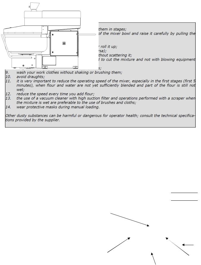
Measures to protect against flour dust
MEASURES FOR THE REDUCTION OF FLOUR DUST EMISSIONS.
The flour is a powdery agent that can impair the operator health (respiratory illnesses), and therefore it must be handled in such way to limit to a minimum the presence of flour dust within the premises.
As concern the machine, if it is equipped with s/s grille, its operating time in the first speed cannot be set up to a value lower than 120 seconds (ref. EN 453) in order to limit the production of flour dust.
Other warnings useful for operators who regularly handle flour are provided below.
15
Instruction for use and maintenance
Spiral mixer with removable bowl SPI 160-300 A HYBRID
PREVENTIVE MEASURES AGAINST NOISE HAZARDS
When the machine is operating empty, which is considered the most unfavourable condition, it emits a weighted equivalent continuous acoustic pressure level of ≤ 70 dB (A).
It can be affirmed that the machine does not produce harmful noise or noise requiring the use of headsets or earplugs.
SECTION A - POINT 6
SAFETY SIGNS - SYMBOLS
The safety signs are affixed to the machine by |
|
means of stickers designed to draw the opera- |
|
tor’s attention to possible hazards and to en- |
B |
sure his safety. |
|
Make sure that the colours and wording of the |
|
signs and symbols are always in perfect condi- |
|
tion. At the first signs of deterioration, imme- |
|
diately request replacements from your sup- |
|
plier or the manufacturer. |
|
F
Figure n° 6
 H
H
 D
D
C
E
G
A
16

English
References SYMBOL DESCRIPTION
A |
DO NOT REMOVE THE SAFETY DEVICES |
B |
CAUTION – DANGER OF CRUSHING |
C |
DANGER – LIVE PARTS |
D |
VOLTAGE |
E |
EARTH |
F BOWL AND TOOL ROTATION DIRECTION
G |
PE |
OUTER PROTECTION WIRE TERMINAL |
|
H |
CAUTION – READ THE INSTRUCTION MANUAL |
17

Instruction for use and maintenance
Spiral mixer with removable bowl SPI 160-300 A HYBRID
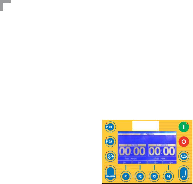
SYMBOLS ON CONTROL PANEL |
|
“Advanced control panel” |
Figure n° 7 |
|
SYMBOL DESCRIPTION
PROGRAMME QUICK RECALL KEY
PROGRAMME QUICK RECALL KEY
BOWL INVERSION
PROGRAMME KEY
FUNCTION KEY
FUNCTION KEY
FUNCTION KEY
SYMBOL DESCRIPTION
FUNCTION KEY
AUTOMATIC/MANUAL CYCLE KEY
CYCLE START KEY
ENTER KEY
CYCLE STOP KEY
EMERGENCY BUTTON
18
English
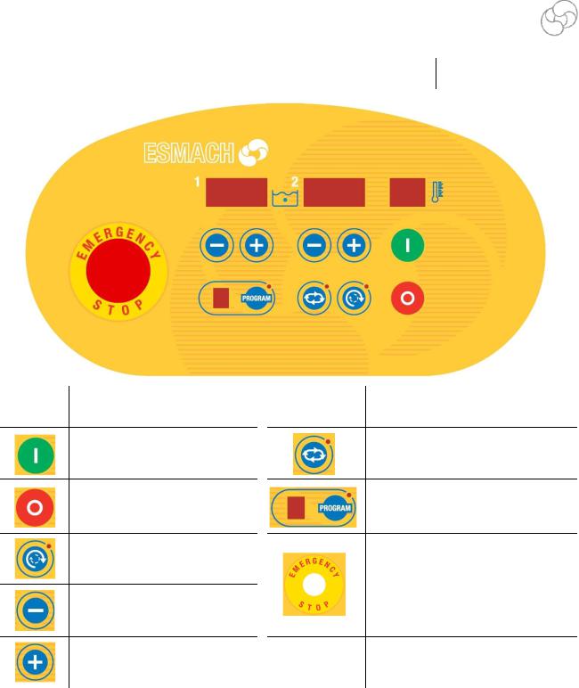
SYMBOLS ON CONTROL PANEL |
|
“Simplified control panel” |
Figure n° 8 |
SYMBOL DESCRIPTION
START CYCLE KEY
STOPO CYCLE KEY
BOWL INVERSION KEY
DECREASING KEY “DOWN”
INCREASING KEY “UP”
SYMBOL DESCRIPTION
AUTOMATIC/MANUAL CYCLE KEY
PROGRAM SELECTION/PROGRAM
CONFIRMATION KEY
EMERGENCY PUSH BUTTON
SECTION B - POINT 1
TRANSPORT, HANDLING AND STORAGE
The weight and overall dimensions of the machine are given in Section A point 2. The machine is shipped assembled and packed in a case/crate/pallet made of nailed wooden boards provided with the symbols and indications for handling. The operators in charge of handling the load must be qualified and adequately trained. Store the machine in a dry ventilated room and cover it with a protective sheet.
will stabilize the machine.
19

Instruction for use and maintenance
Spiral mixer with removable bowl SPI 160-300 A HYBRID
EXAMPLE OF MACHINE UNLOADING WITH FORKLIFT TRUCK
Stage 1: Unload the machine from the lorry in its packaging;
Stage 2: Rest the machine on the ground;
Stage 3: Unpack the machine;
Stage 4: Make sure that the machine in its complex is in equilibrium .
Stage 5: Make sure that the brackets for lifting are properly inserted on the feet of the machine and fixed with nuts of the same feet.
FIXING NUTS
BRACKET FOR
LIFTING
Stage 6: Lift the machine avoiding sudden movements.
Stage 7: Only after standing the machine DOWN in the desired position, loosen the nuts on the feet and remove the brackets from the side. The nuts will be fixed later when it will stabilize the machine.
20
English
PROCEDURES FOR UNLOADING THE MACHINE USING A CRANE OR HOIST
Unloading personnel must be equipped with chains or ropes compatible with the weight and dimensions of the machine to be moved and in compliance with current safety regulations.
IMPORTANT WARNINGS !
-The slings must comply with ISO 4878 - ISO 9351 standards.
-Use the sling only if the label containing all the manufacturer information is affixed to it and the capacity is clearly visible.
-Inspect the slings before all lifting operations. Do not use them if they are damaged, cut or worn.
-Follow the load factors indicated for the various standardised configurations.
-Use adequate protection for lifting loads with sharp edges.
-Do not twist or knot the sling.
-Insert the other ends of the slings in the lifting equipment hook.
-Before moving the machine, ensure that there are no persons nearby.
-Carefully follow the unloading procedures described below.
1.remove the cover screws as per figure n°10
Figure n° 10
2.lift the rear cover
3.lean with care the cover
4.lift the machine:
-machine with jointed trolley : pass the belt in the front part of the central tube (Figure n° 11).
-pass the belts in the two eyebolts on the side of the head attached to the top of the column (Figures n ° 12 - 13).
Figure n° 11 |
Figure n° 12 |
Figure n° 13 |
21

Instruction for use and maintenance
Spiral mixer with removable bowl SPI 160-300 A HYBRID
SECTION B – POINT 2
PREPARING THE ROOM - INSTALLING THE MACHINE
PREPARING THE ROOM
The room where the machine is installed and any existing equipment already installed in the room must comply with the directives, regulations, standards and technical specifications etc. in force in the user’s country (E.U. or EFTA).
INSTALLING THE MACHINE
The purchaser/user or his representative must check the condition of the machine upon unpacking, immediately notifying the manufacturer of any damage or defects encountered.
For installation of the machine, the specifications on the identification label illustrated in Section A point 1 and the overall dimensions given in Section A point 2 should be taken into account. To guarantee an optimal use of the machine it is necessary to follow the present installing procedure:
1. clean accurately the floor zone on which will be placed the ma- |
Figure n° 14 |
|
|
chine so that the feet with anti-slide rubber have a better adhe- |
|
sion to the floor (figure n° 14) |
|
2.Put the machine on the floor making sure there is an area of approximately 50 cm all around the machine for use and maintenance
Figure n° 15
3.fix the safety spacer tube (figure n°15) of the machine in the rear zone in order to let the head raise automatically and avoid accidental crushing of the operators between the cover and the wall under the machine
Figure n° 16
4.at this point switch on the machine (figure n° 16) following the instructions as per Section B—Point 3
Figure n° 17
5. after having verified that all runs in the correct way, push contemporarily the common button and the button to lift the head and unhook the trolley (figure n° 17)
22

English
6.By means of the spacer (which is in the machine equipments) act on the feet in order to carry the two chutes of the frontal rostrum at a right height from the floor (figure n°1819),
figure n° 18 |
|
figure n° 19 |
|
|
|
NB: it is indispensable that all feet are well fitted on the floor.
figure n°20
7. Put the trolley in the machine and hook it (figure n° 20)
8. Verify that the distance from the floor and the wheels under the trolley in the hooking position is at least the thickness of a sheet of paper.
9. if the wheel touch the floor it must lift again the feet so that the wheels became free.
10.Now it must block the feet tightening nut with the key (equipment).
The machine is designed to operate in the normal temperature and humidity conditions found in EU and EFTA countries.
The machine must not under any circumstances be used in places where there is the danger of explosion or fire due to the presence or generation of dust, gas or explosive or flammable mixtures.
For connection of the machine to the electrical power source, see points 4 and 5 of Section B.
NOTE: For connections in the US/Canada:
An electrician licensed under the jurisdiction (city, municipality, county, state, etc.) in which the mixer will be installed must install the plug that meets requirements in sub-clauses 4.5.2.2 of C22.2 No. 195 and 6.2.1, 11.1.1, 15.1.6 of UL 763.
23

Instruction for use and maintenance
Spiral mixer with removable bowl SPI 160-300 A HYBRID
SECTION B – POINT 3
START-UP, USE AND ADJUSTMENTS
START-UP
One single trained and instructed operator is sufficient for use of the machine according to this handbook.
IMPORTANT WARNINGS
Before starting the machine, follow the instructions below:
1.Check that the machine voltage, indicated in the identification label illustrated in Section A, point 1, corresponds to the line voltage at the socket. If not, suspend the connection operations and call the supplier or the manufacturer.
2.Turn the master switch to position 1. The display must be on. Make sure that the emergency buttons on the card and on the side of the electric box are not pressed. If the trolley is hooked and the head is lowered, press at the same time the common and upstroke buttons (keys 3 and 6 as shown by the machine controls). When these two buttons are pressed, the head lifts. This means that the pump turns correctly. If not, invert the phases on the electrical plug.
24

English
MACHINE CONTROLS:
“Advanced control panel”
Figure n°21 |
|
|
13 |
12 |
1 |
3 |
2 |
legend: |
4 |
5 |
6 |
7 |
8 |
9 |
|
10 |
11 |
|
|
|
|
|
|
|
|
|
|
|
|
|
|
||
|
|
|
|
|
|
|
|
|
|
|
|
|
|
|
DESCRIPTION |
FUNCTION |
|
|
|
|
|
|
|
|
|
|
|
|
|
|||||||||
|
|
|
When it is pressed, it stops the machine and locks all possible |
|||||||||
1 |
EMERGENCY BUTTON |
movements. Turn it clockwise to unlock the button. |
|
|
||||||||
|
|
|
Note: there are two emergency push buttons (ref. 17) |
|
|
|||||||
|
|
|
|
|
|
|
|
|
|
|
||
2 |
PROGRAMME QUICK RE- When |
it is |
pressed, |
it |
recalls |
the |
main |
programme |
n° |
1 |
||
|
|
CALL KEY |
(without access to programming). |
|
|
|
|
|
||||
|
|
|
|
|
|
|
|
|
|
|
||
3 |
PROGRAMME QUICK RE- When |
it is |
pressed, |
it |
recalls |
the |
main |
programme |
n° |
2 |
||
|
|
CALL KEY |
(without access to programming). |
|
|
|
|
|
||||
|
|
|
|
|||||||||
|
|
|
When it is pressed, it inverts the bowl motion (led on). Inver- |
|||||||||
|
|
|
sion is possible only when the spiral turns at low speed and not |
|||||||||
4BOWL INVERSION in programming mode. (programs from10 to 99)
When it is pressed during recipe programming it insert the inversion phase
25

Instruction for use and maintenance
Spiral mixer with removable bowl SPI 160-300 A HYBRID
|
DESCRIPTION |
FUNCTION |
|
|
|
|
|
|
|
Pressing it one time you can recall the last program you set |
|
|
|
up. |
|
|
|
When it is pressed twice, it displays the list of all 99 recipes. |
|
5 |
PROGRAMME KEY |
After having selected the recipe, it is possible to start the |
|
|
|
working cycle pressing the START key (if the situation allows |
|
|
|
starting). During programming the led on the left of the key is |
|
|
|
on. |
|
|
|
|
|
|
FUNCTION KEY |
The key can have different functions according to what the dis- |
|
6 |
play shows. |
||
F1 |
|||
|
The key function is displayed in the down line |
||
|
|
||
|
|
|
|
|
FUNCTION KEY |
The key can have different functions according to what the dis- |
|
7 |
play shows. |
||
F2 |
|||
|
The key function is displayed in the down line |
||
|
|
||
|
|
|
|
|
FUNCTION KEY |
The key can have different functions according to what the dis- |
|
8 |
play shows. |
||
F3 |
|||
|
The key function is displayed in the down line |
||
|
|
||
|
|
|
|
|
FUNCTION KEY |
The key can have different functions according to what the dis- |
|
9 |
play shows. |
||
F4 |
|||
|
The key function is displayed in the down line |
||
|
|
||
|
|
|
|
|
|
It allows entering or exiting from recipe programming. For |
|
10 |
ENTER KEY |
these operations, the key has to be kept pressed for 3 seconds |
|
|
|
until is displayed “insert code”. |
|
|
|
|
|
11 |
AUTOMATIC/MANUAL |
It allows changing from manual cycle to automatic cycle. Dur- |
|
|
CYCLE KEY |
ing the automatic cycle the led on the right of the key is on. |
|
|
|
|
|
|
|
1-When it is pressed, it stops the machine. If pressed during |
|
|
|
the machine running it allows the cycle stopping and times |
|
12 |
CYCLE STOP KEY |
memorization. |
|
|
|
2-if pressed twice during the machine running, it allows the |
|
|
|
machine stopping and the working times restoring. |
|
|
|
|
|
|
|
When it is pressed, it starts the mixing cycle. The cycle can |
|
13 |
CYCLE START KEY |
starts only if the head is in work position and there is no emer- |
|
|
|
gency. |
|
|
|
|
26

|
|
English |
|
|
DESCRIPTION |
FUNCTION |
|
|
|
|
|
|
|
Common button for trolley hooking/unhooking and head up- |
|
|
|
stroke/downstroke. This button has to be pressed at the same |
|
14 |
MACHINE HANDLING |
time of the buttons 15-16. |
|
COMMON BUTTON |
When it is pressed alone for at least 0,5 sec. at upstroke head |
||
|
|||
|
|
without trolley, it allows the hook lowering to make easier the |
|
|
|
trolley connection in case of not levelled floor. |
|
|
|
|
|
|
HEAD UPSTROKE / |
When it is pressed together with button 14, it allows to lift the |
|
15 |
TROLLEY UNHOOKING |
||
head and, once the head is lifted, to unhook the trolley. |
|||
|
BUTTON |
|
|
|
|
|
|
|
HEAD DOWNSTROKE / |
If pressed together with the button 14, it hooks the trolley |
|
16 |
and, at hooked trolley pressing the same buttons it allows the |
||
TROLLEY HOOKING BUT- |
head lower |
||
|
TON |
||
|
|
||
|
|
|
Figure n°22
Figure n°23
27
Instruction for use and maintenance
Spiral mixer with removable bowl SPI 160-300 A HYBRID
WORKING CYCLE START – AUTOMATIC WORKING
Trolley hooking / Head downstroke / Head upstroke / Trolley unhooking
To hook the trolley, place the trolley near the machine and follow the instructions below:
Press at the same time the buttons on the two sides of the box (common button “14” and downstroke button “16”)
When the trolley is hooked, the head begins to lower. Keep buttons pressed until the head has gained the work position (head down). The trolley unhook is automatic only when the head is completely upstroke.
All controls are of hands-on type.
If the floor has a slope opposite to the unit and the trolley into position goes away from the machine, it is possible to pre-hook the trolley by pressing the common key. “14” for at least 3 seconds.
MANUAL CYCLE WORKING H (figure n° 24)
The manual cycle is available if key leds n°5 and 10 are off. Contrarily, touch over and over on key “11” utill “MANUAL (H) “ appears.
When the START key 13 is pressed, the machine begins to work at the 1 st speed. The time on the 1 st speed left timer increases.
During this phase it is possible to invert the bowl direction by pressing the key 4.
The machine works at the 2 nd speed by pressing again the START key.
The machine can work |
at 2 nd speed only if the |
minimum time in 1 st |
speed (minimum 2 min- |
utes) has been spent. |
|
The time on the 2 nd speed right timer increases. The machine works at the 1 st speed by pressing again the START key,
You can change the bowl speed at the 1 st speed with the function keys F1-F2 (ADJ from +50-50). You can change the bowl speed at the 2 nd speed with the function keys F3-F4 (ADJ from + 5050).
The machine stops by pressing the STOP key 12. The timer count is reset by pressing again the STOP key.
AUTOMATIC CYCLE WORKING “0”
Press the key 11 to change from the programme MANUAL H to the programme AUTOMATIC 0. The led must light on (figure n°30).
Set the working time at the 1 st speed with the function keys F1-F2. Set the working time at the 2 nd speed with the function keys F3-F4. Press the START key 13 to start the cycle.
If you press the ENTER key, the last line of the display shows the bowl speed variation at first and second speed as already explained for THE MANUAL CYCLE.
If you do not press one of the keys F1-F2-F3-F4 within 3 seconds, with these buttons you do not change the bowl speed but times are increased.
28

English
RECIPES - LIST |
|
|
It is possible to memory two kinds of recipes: |
|
|
Figura n°25 |
||
simple recipes: numbered from 1 to 9 in which |
||
|
||
it is possible to recorder the dough times, the |
|
|
|
||
bowl speed and in case the automatic up- |
|
|
stroke |
|
|
recipes with variations: from n° 10 to n° 99, |
|
|
in addition to the functions described in |
|
|
point a), the following can be programmed and |
|
|
stored: addition of salt, improver, temperature |
|
|
control and raising of the head at the end of the |
|
|
cycle (only if the machine is provided |
|
|
with the relevant optionals). |
|
Figure n°26 |
|
|
|
|
|
|
|
|
||
|
|
|
|
|
|
|
|
The names of the recipes are shown by pressing |
||
-05- |
|
RECIPE N. 05 |
||||||||
|
|
|
|
|
|
|
|
the key PROG. With the keys F4-F3 you can se- |
||
SELECT RECIPE |
lect a new recipe. |
|||||||||
Confirm by pressing the key F2. |
||||||||||
05:RECIPE N.05 |
|
|
|
|
|
|
Exit from the list of the recipes by using the key |
|||
06:RECIPE N.06 |
|
|
|
|
|
|
F1. You go back to the previous recipe if you do |
|||
07:RECIPE N.07 |
|
|
|
|
|
|
||||
|
|
|
|
|
|
not confirm by pressing the key F2. |
||||
08:RECIPE N.08 |
|
|
|
|
|
|
||||
09:RECIPE N.09 |
|
|
|
|
|
|
Start the work cycle by pressing the key START. |
|||
10:RECIPE N.10 |
|
|
|
|
|
|
||||
|
|
|
|
|
|
To recorder the automatic up-stroke at the end |
||||
11:RECIPE N.11 |
|
|
|
|
|
|
||||
|
|
|
|
|
|
of cycle in the simple recipes you must: |
||||
12:RECIPE N.12 |
|
|
|
|
|
|
||||
|
|
|
|
|
|
|
|
▪ |
push ENTER key |
|
ESC |
|
OK |
|
|
|
|
|
▪ |
digit the programming access code “250” |
|
|
|
|
|
|
|
|||||
|
|
|
|
|
|
|
|
confirming it with ENTER key. |
||
▪ move in the |
proper box with F1/F2 keys |
|||||||||
|
|
|||||||||
▪select “yes” or “not” with key F3/F4 confirming than with ENTER.
▪With “P01” and “P02” you can recall possible priority programs.
▪To relate the program to the recipe see “list of parameter modifiable by the user”
RECIPES WORKING Press twice STOP key.
Press the key PROG: the led is on.
The last selected recipe is shown (figure n° 27).
-11 - |
|
RECIPE N. 11 |
||
|
|
|
PHASES |
|
|
RECIPE |
|||
|
|
|||
PHASE NUMBER:04 |
TOTAL TIME : 05.30 |
|||
NAME |
|
:RECIPE N.11 |
||
MAX TEMP. |
|
°C :25.2 |
||
TEMP. CONTROL |
:No |
|||
INSERT THE CODE : 255
Figure n°27 |
TAB |
EDIT |
29

Instruction for use and maintenance
Spiral mixer with removable bowl SPI 160-300 A HYBRID
Only if present on the machine, Figure n°28 the display shows the accessory
salt, improver, temperature
To enter in programming or modify a recipe press the key Enter “10” for 3 seconds.
The enter code is required. (figure n° 28).
Figure n°29
-11 - |
|
RECIPE N. 11 |
||||
PHASE NUMBER : 00 |
|
|
|
22°C |
||
TOTAL TIME: 00.00 |
|
|
|
|
||
NAME |
|
|
|
: RICETTA N. 11 |
||
UP-STROKE |
|
|
|
: yes |
||
T. SALT |
|
: 00.10 |
|
|||
T. IMPROVER |
|
: 00,10 |
|
|||
MAX. TEMP |
|
°C : 25.2 |
||||
TEMP. CONTROL |
|
|
: si |
|||
F01 STOP |
|
: |
|
|||
|
|
|
|
|
|
|
|
|
|
|
|
|
|
-11 - |
|
RECIPE N. 11 |
|
|||
PHSE NUMBER |
: 00 |
|
|
|
22°C |
|
TOTAL TIME |
: 00.00 |
|
|
|
|
|
NAME |
|
|
|
: RICETTA N. 11 |
||
UP-STROKE |
|
|
|
: yes |
|
|
T. SALT |
|
|
|
: 00.10 |
|
|
T. IMPROVER |
|
|
|
: 00.10 |
|
|
MAX. TEMP. |
°C |
: 25.2 |
|
|||
TEMP. CONTROL |
: Si |
|
||||
F01 STOP |
|
|
|
: |
|
|
INSERT THE CODE : 250 |
|
|
||||
|
|
|
|
|
|
|
|
|
|
|
|
[-] |
[+] |
Set the value 250 with the keys F3-F4 (figure n° 29) and confirm with Enter key.
Figure n°30
Now the cursor is on the first letter of recipe name.
The keys F3-F4 let run through the character The keys F1-F2 let move to the right or to the left.
The F2 key lets go to the next phase (salt distribution, improver , upstroke ...):the distribution time must be counted from the cycle end (example: total kneading time =10 minutes; salt distribution time: 3 minutes; the salt will be distributed at the 7th minutes form the beginning of the cycle)
-11- |
RECIPE N. 11 |
|
PHASE NUMBER : 00 |
22°C |
|
TOTAL TIME |
: 00.00 |
|
NAME |
|
: RICETTA N. 11 |
UPSTROKE |
|
: yes |
T. SALT |
|
: 03.00 |
T. IMPROVER |
|
: 00.10 |
MAX. TEMP. |
°C |
: 25.20 |
TEMP. CONTROL |
: si |
|
F01 STOP |
|
: |
RECIPE MODIFICATION >Stop<TO EXIT
[-] [+]
UP-STROKE
By setting “yes”, 10 seconds after the end of mixing, the head moves up automatically until it reaches the raised position. The trolley is manually released. To release the trolley, simply press the common buttons “18” and up button “19” for 0.5 seconds.
By setting “no”, at the end of mixing, the head must be raised manually by simultaneously pressing the common buttons “18” and up button “19”.
30
 Loading...