

Page 1
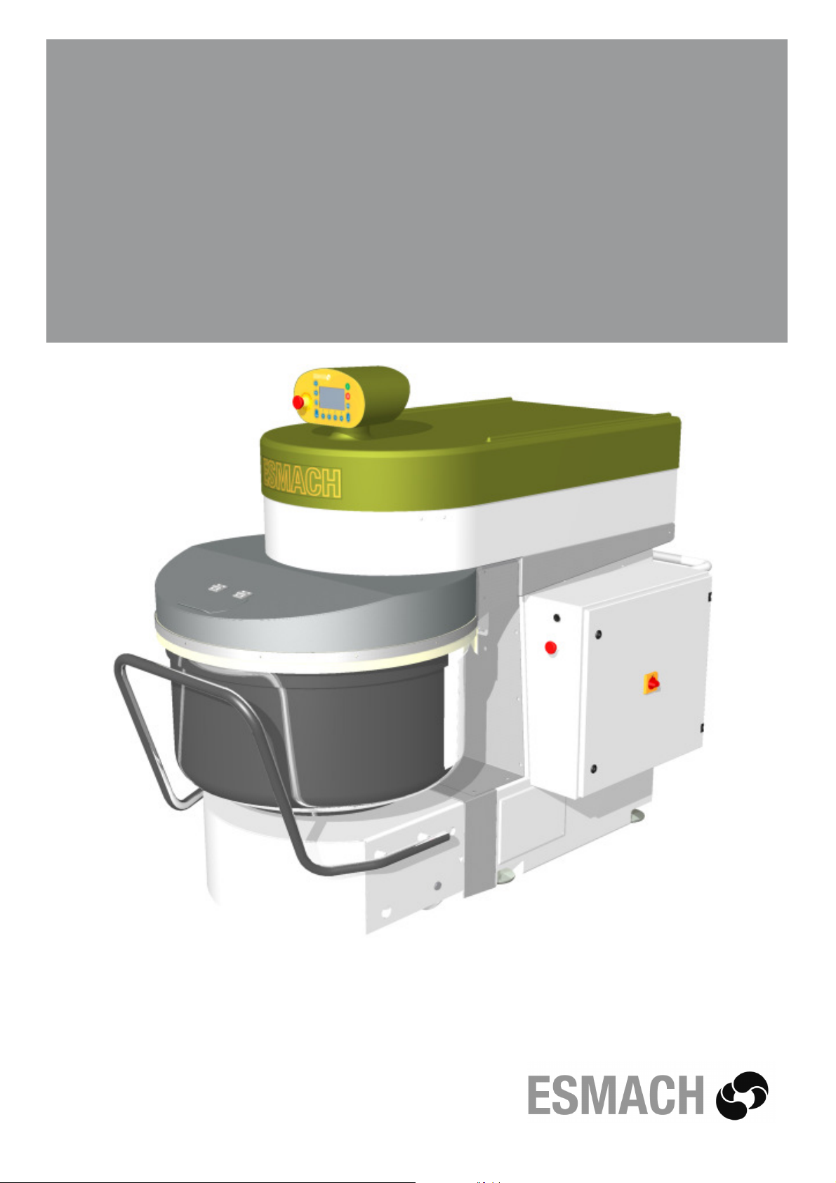
SPIRAL MIXER WITH REMOVABLE BOWL
PETRIN A SPIRALE A CUVE FIXE
IMPASTATRICE A SPIRALE A VASCA ESTRAIBILE
SPI 160-300 A
HYBRID
Code/codice N° 876577 rev. 02
February/Février/Febbraio 2014
Instruction for use and maintenance
Notice d’utilisation et de maintenance
Istruzioni uso e manutenzione
Page 2

Page 3

CAREFULLY READ THIS INSTRUCTION
MANUAL BEFORE OPERATING THE MACHINE.
OBSERVE ALL SAFETY REGULATIONS AND INSTRUCTIONS
DURING OPERATION OF THE MACHINE.
LIRE ATTENTIVEMENT CE MANUEL D’INSTRUCTIONS
AVANT DE METTRE EN ROUTE LA MACHINE.
OBSERVER LES CONDITIONS ET LES INSTRUCTIONS DE SECURITE PENDANT
LE FONCTIONNEMENT DE LA MACHINE
LEGGERE ATTENTAMENTE IL PRESENTE MANUALE D’ISTRUZIONI
PRIMA DI FAR FUNZIONARE LA MACCHINA.
OSSERVARE LE NORME E LE ISTRUZIONI DI SICUREZZA
DURANTE IL FUNZIONAMENTO DELLA MACCHINA
GENERAL INDEX/INDICE GENERAL/INDICE GENERALE
ENGLISH P. 5
FRANÇAIS P. 57
ITALIANO P. 107
Tables with spare parts
Planches avec des pièces de rechange
P. 159
Tavole con ricambi
Page 4

Page 5

English
English
5
Page 6

Page 7

English
TABLE OF CONTENTS
Page
Introduction, general warnings and warranty rules 9
1. Machine identification 10
2. Technical specifications 11
3. Application 13
SECTION A 4. Machine description 13
5. Preventive measures against health and safety hazards 13
6. Safety signs - symbols 16
1. Transport, handling and storage 20
2. Preparing the room - Installing the machine 22
3. Start-up, use and adjustments 24
SECTION B 4. Troubleshooting 45
5. Food hygiene and cleaning 47
6. Maintenance and checks 48
7. Replacing worn parts 53
SECTION C 1. Emergency situations 53
2. Decommissioning - scrapping 53
ALPHABETICAL INDEX
application 13
decommissioning, scrapping 53
emergency situations 53
food hygiene and cleaning 47
general warnings 9
introduction 9
machine controls 25
machine description 13
machine identification 10
machine installation 22
maintenance and checks 48
maintenance to be performed by the manufacturer's authorised service department 48
maintenance to be performed by the operator 48
preparing the room 22
preventive measures against electrical hazards 15
preventive measures against health and safety hazards 13
preventive measures against mechanical hazards 14
preventive measures against noise hazards 16
preventive measures to guarantee hygiene 15
replace of worn out parts 53
Routine maintenance sheet 52
safety signs - symbols 16
start-up, use and adjustments 24
technical specifications 11
transport, handling and storage 20
troubleshouting 44
warranty rules 10
7
Page 8

Page 9

English
INTRODUCTION, GENERAL WARNINGS AND WARRANTY RULES
INTRODUCTION
This instruction manual has been designed and organised for quick easy reference. For this purpose, in addition to the INTRODUCTION and GENERAL WARNINGS, it contains a TABLE OF CONTENTS and an INDEX.
For each topic discussed, illustrations and tables are provided beside the corresponding text to
facilitate understanding.
The instruction manual is divided into SECTIONS.
For the topics discussed in each SECTION, refer to the detailed TABLE OF CONTENTS.
GENERAL WARNINGS
This instruction manual is intended for the owner/user of the machine, the personnel employed
by the latter in positions of responsibility within the company and personnel assigned to handling, installation, use, supervision, maintenance and scrapping of the machine etc.
This manual provides information on the technical specifications and scheduled use of the machine, instructions/indications/information on handling, installation, assembly, adjustment and
use in addition to information on personnel training in order to facilitate maintenance work, troubleshooting, ordering of spare parts, residual risk assessment etc.
This manual forms an integral part of the MACHINE which is DESIGNED FOR PROFESSIONAL
USE but the manual should never be considered a substitute for adequate user training and experience. Operations requiring personnel with specific skills are highlighted in the manual.
The manufacturer reminds its customers, i.e. users of the machine, that they are also required
to observe the specific legislation concerning places of work and that adequacy and conformity
of the work place with current regulations are essential conditions for correct installation and use
of the machine.
This manual should be considered part of the machine and must be kept for future reference until the machine is scrapped.
This manual must be kept in a dry easily accessible place, preferably within easy reach of the
machine.
The manufacturer reserves the right to update the machine and instruction manuals without being obliged to update machines and/or manuals produced previously, barring exceptional circumstances. On request, however, the manufacturer will provide customers with any further information they may require.
If the machine is sold, customers (users) are kindly requested to notify the manufacturer of the
address of the new owner for the above-mentioned purpose.
The manufacturer accepts no liability in the event of the following:
a. inappropriate use of the machine or use by personnel not trained to operate professional
machines
b. use not in compliance with specific national regulations
c. incorrect installation
d. power supply faults
e. lack of maintenance
f. unauthorised modifications or work
9
Page 10
Instruction for use and maintenance
Spiral mixer with removable bowl SPI 160-300 A HYBRID
g. use of non-original spare parts or parts not specifically intended for the model
h. total or partial failure to observe the instructions
i. exceptional events etc.
WARRANTY RULES
The machine is guaranteed for 12 (twelve) consecutive months from the date of purchase on
condition that it is used according to the instructions contained in this manual. The warranty
lapses if the machine has been used without following the directions contained in the manual or
if the machine has been repaired, disassembled or modified by unauthorised workshops or aftersales centres. All electrical parts are excluded from the warranty if the damage has been caused
by incorrect use of the machine.
SECTION A - POINT 1
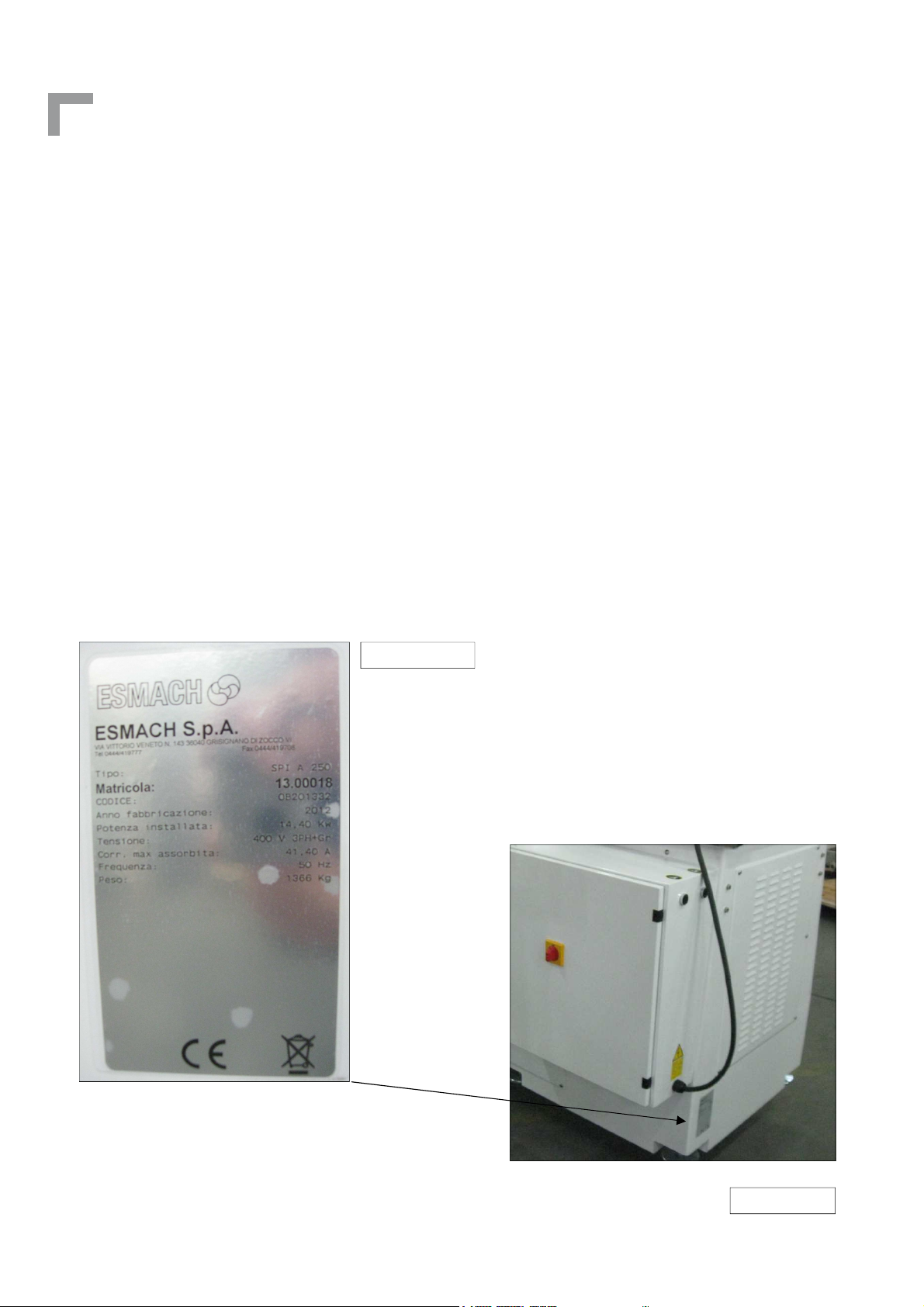
MACHINE IDENTIFICATION
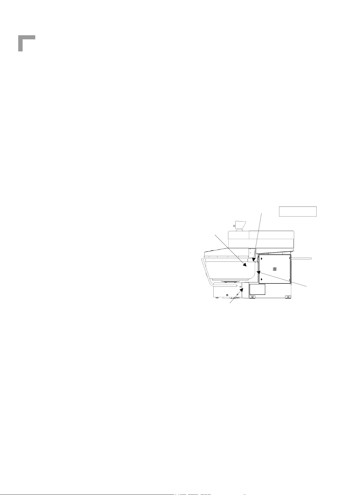
Figure n° 1 shows the plate affixed to the machine in the position indicated by the arrow in figure n° 2. The plate contains all the information necessary for identifying the machine.
Figure n° 1
Figure n° 1
10
Figure n° 2
Page 11
English
SECTION A - POINT 2
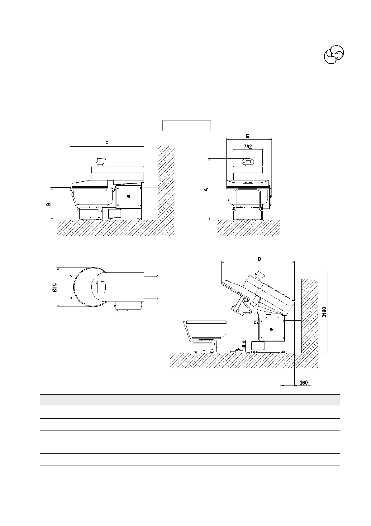
TECHNICAL SPECIFICATIONS
The main technical specifications of the machine are illustrated and indicated in figure n° 3 and in
tables on the following page.
Figure n° 3
Bowl rotation direction
(overhead view): anticlockwise
SPI A Hybrid 160 200 250 300
A mm 1656 1656 1654 1654
B mm 832 892 857 937
C mm 900 900 1045 1045
D mm 1862 1833 1954 1913
E mm 1127 1127 1200 1200
F mm 1860 1860 1983 1983
11
Page 12

Instruction for use and maintenance
Spiral mixer with removable bowl SPI 160-300 A HYBRID
TECHNICAL DATA 160 200 250 300
Maximum mixture capacity kg 160 200 250 300
Maximum flour capacity kg 100 125 150 185
Total capacity litres 250 300 360 430
Spiral arm speed 50 Hz (*) r.p.m. 86-172 86-172 86-172 86-172
Bowl speed 50 Hz (*) r.p.m. 9-18 9-18 10-20 10-20
Spiral arm speed 60 Hz (*) r.p.m. 103-206 103-206 103-206 103-206
Bowl speed 60 Hz (*) r.p.m. 10.8-21.6 10.8-21.6 12-24 12-24
Power with 50 Hz kW 10,1 10,1 12,9 12,9
Power with 60 Hz kW 12,9 12,9 15,1 15,1
Packaging volume m3 4,4 4,4 4,4 4,4
Net weight of machine kg 1210 1220 1370 1380
(*) indicative value
12
Page 13
English
SECTION A - POINT 3
APPLICATION
The spiral mixer, also called “machine” in this manual, is designed exclusively for blending flour
for bread, cakes and other baked products with ingredients such as sugar, fat, salt, water, yeast
etc. in bakeries and food shops. A very wide variety of ingredients can be mixed. The complete
operation normally consists of a number of cycles of varying duration.
Use of the machine for purposes other than those specified above is dangerous for the operator
and for the machine itself. In the same way, machine installation and/or operation procedures
other than those specified in Section B points 2 and 3 can injure the operator and damage the
machine.
.
SEZIONE A - PUNTO 4
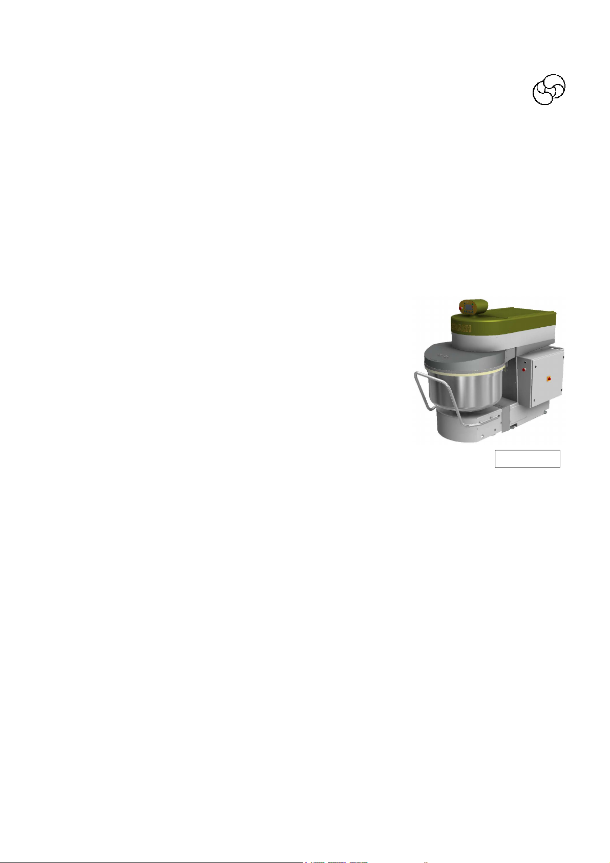
MACHINE DESCRIPTION
The machine consists basically of:
▪ one fixed structure with
- on the side the switchboard and the operating devices
- inside are the mechanical transmission parts:
-for the head upstroke
-for trolley coupling
-for bowl transmission
▪ a mobile head bound to the fixed structure equipped with:
- a tool for mixing the ingredients
- a central bar that guarantees a better dough oxygenation
- an electronic panel placed in the machine front part.
▪ a removable trolley
- a bowl for containing the ingredients to be mixed
- all the organs that allows the coupling to the central structure
Main features:
-the machine emits a weighted equivalent continuous acoustic pressure level ≤ of 70 dB (A).
-The machine as a whole is protected to IP 44.
Note:
Further details of the machine with illustrations are given in Section B point 3.
SECTION A - POINT 5
PREVENTIVE MEASURES AGAINST HEALTH AND SAFETY HAZARDS
In design and construction of the machine, the manufacturer has taken into account the results
of a previous assessment of SAFETY AND HEALTH hazards relating to use of the machine.
The protections and safety devices fitted on the machine are therefore the result of the company’s considerable efforts to achieve state-of-the-art safety levels as indicated in the specific
EEC directives.
Figure n° 4
13
Page 14
Instruction for use and maintenance
Spiral mixer with removable bowl SPI 160-300 A HYBRID
The machine conforms to:
▪ the Directive 98/37 CEE
▪ the Directive CEM 89/336 CEE
▪ the Directive BT 73/23 CEE
▪ the specific product standard EN 453 dated August 1999 where the major apllicable stan-
dard are listed.
The machine complies with the laws in effet when it was delivered.
To adapt the equipment to any subsequent modification of standards is under the responsability
of the user. In this case, he has to ask the manufacturer whether a modification is necessary.
PREVENTIVE MEASURES AGAINST MECHANICAL HAZARDS
TOOL (SPIRAL ARM) OPERATING AREA
(Figure n° 5 zone 1)
The bowl is protected in the front part with a stainless steel closed protection and in the rear
part with a flour protection sheet.
The head and its protection opening is temporized as per EN 453 to let the toll stops in 4 seconds from the opening of the machine head.
5
Figura n° 5
SPACE BETWEEN BOWL AND STRUCTURE (Figure n° 5
zone 2)
It conforms to the specific product standard EN 453.
1
4
MECHANISM OF BOWL MOVEMENT (Figure n° 5 zone 3)
Parts in movement advised by warning stickers in order
to maintain the safety.
POSITIONING AND ADJUSTING MECHANISMS
2
(Figure n° 5 zone 4)
All motions of the machine are essentially made by hold-to-run control devices (double
3
push buttons) and doesn’t present risks for the operator.
Note: the operator must be sure there is no person near the machine.
Remove the guards with the specific tools, to accede to the moving elements of the transmission
for inspection, cleaning and maintenance purpose.
BOWL GUIDE DEVICE (figure n° 5 zone 5)
The zone is protected by fixed guards as per EN 453.
In any case we suggest to not insert the fingers in that zone to avoid possible crushing
14
Page 15

English
MACHINE STABILITY
The mixer is provided with adjustable feet with anti-slide rubber.
After having correctly positioned the feet (as explained in SECTION B POINT 2), the machine becomes automatically stable and does not require anchoring to the floor
PREVENTIVE MEASURES AGAINST ELECTRICAL HAZARDS
The preventive measures provided for by the EN 60204-1 standard have been adopted against
the danger of direct and indirect contact and all the tests provided for by the above standard
have been performed as certified in the attachment to the EC declaration of conformity. All the
tests provided for by the current technical regulations have also been carried out for implementation of the EEC directive on EMC.
PREVENTIVE MEASURES TO GUARANTEE HYGIENE
The following should be noted in particular:
A. The elements or parts of the machine (bowl, tool, dividing blade and bowl protection) that are
meant to come in contact with the dough ingredients or are in the so-called FOOD AREA are
made of STAINLESS STEEL (the bowl protection can be made of Transparent thermoformed
suitable for contact with food).
B. The elements or parts of the machine that may come into contact with the above food
products or are in the so-called DIRTYING OR SPLASH AREA are made of STAINLESS STEEL
or OVEN PAINTED STEEL.
C. The machine is in conformity with the principles of design to ensure the cleanability of the
machine as per EN 453.
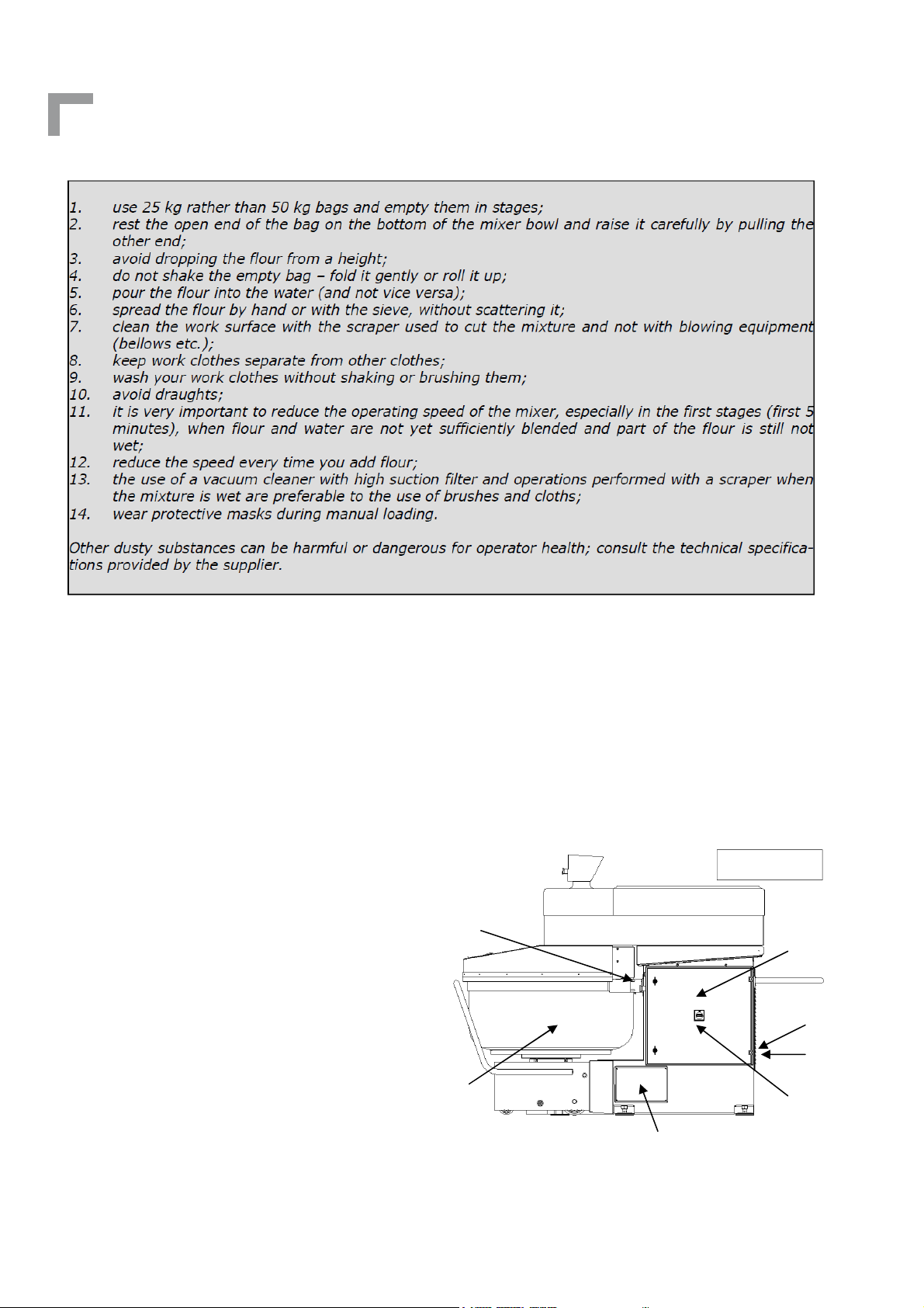
Measures to protect against flour dust
MEASURES FOR THE REDUCTION OF FLOUR DUST EMISSIONS.
The flour is a powdery agent that can impair the operator health (respiratory illnesses), and
therefore it must be handled in such way to limit to a minimum the presence of flour dust within
the premises.
As concern the machine, if it is equipped with s/s grille, its operating time in the first speed cannot be set up to a value lower than 120 seconds (ref. EN 453) in order to limit the production of
flour dust.
Other warnings useful for operators who regularly handle flour are provided below.
15
Page 16
Instruction for use and maintenance
Spiral mixer with removable bowl SPI 160-300 A HYBRID
PREVENTIVE MEASURES AGAINST NOISE HAZARDS
When the machine is operating empty, which is considered the most unfavourable condition, it
emits a weighted equivalent continuous acoustic pressure level of ≤ 70 dB (A).
It can be affirmed that the machine does not produce harmful noise or noise requiring the use
of headsets or earplugs.
SECTION A - POINT 6
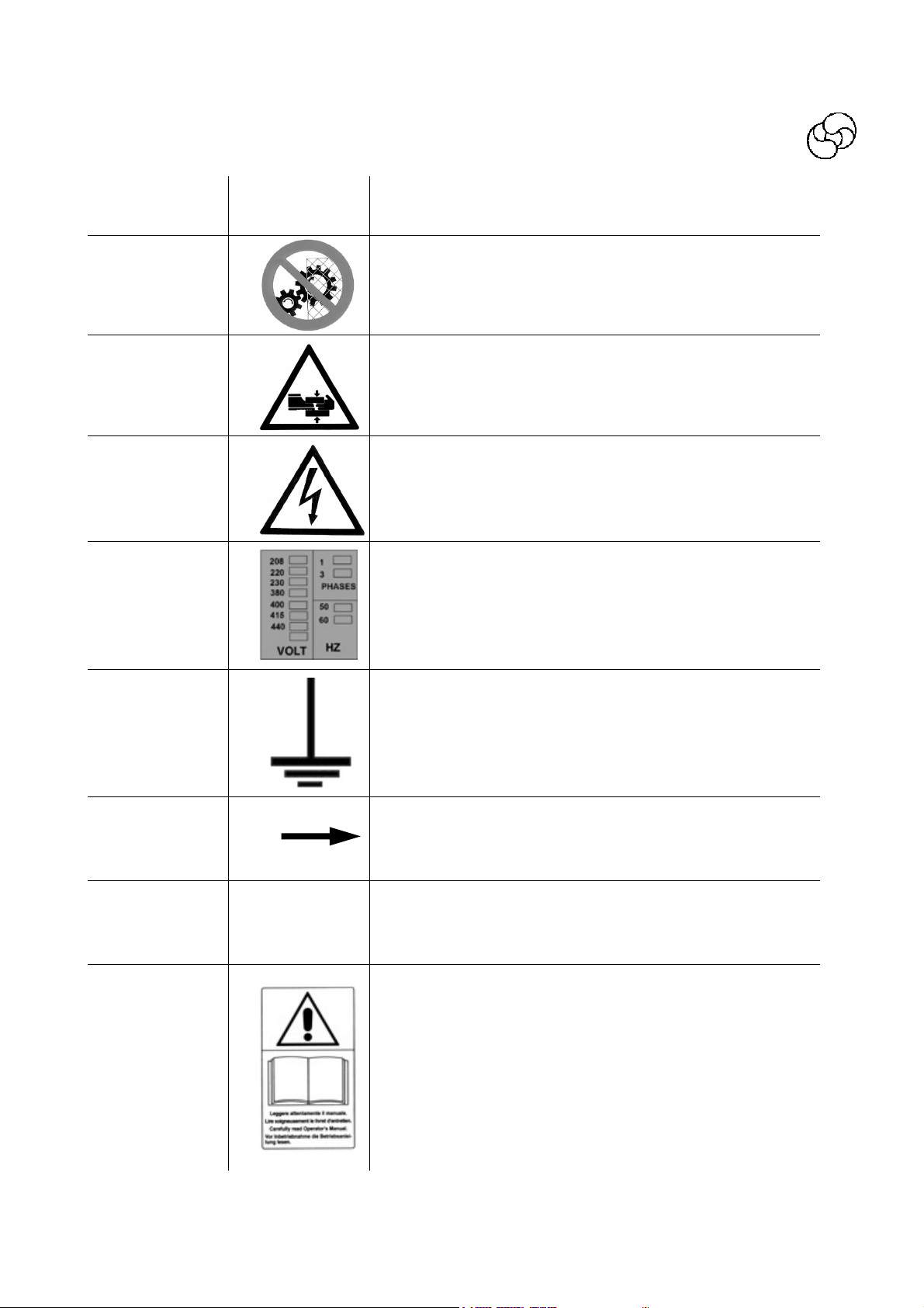
SAFETY SIGNS - SYMBOLS
The safety signs are affixed to the machine by
means of stickers designed to draw the operator’s attention to possible hazards and to ensure his safety.
Make sure that the colours and wording of the
signs and symbols are always in perfect condition. At the first signs of deterioration, immediately request replacements from your supplier or the manufacturer.
B
Figure n° 6
H
D
C
16
F
E
G
A
Page 17
English
References
A
B
C
D
SYMBOL DESCRIPTION
DO NOT REMOVE THE SAFETY DEVICES
CAUTION – DANGER OF CRUSHING
DANGER – LIVE PARTS
VOLTAGE
E
F
G
H
PE
EARTH
BOWL AND TOOL ROTATION DIRECTION
OUTER PROTECTION WIRE TERMINAL
CAUTION – READ THE INSTRUCTION MANUAL
17
Page 18
Instruction for use and maintenance
Spiral mixer with removable bowl SPI 160-300 A HYBRID
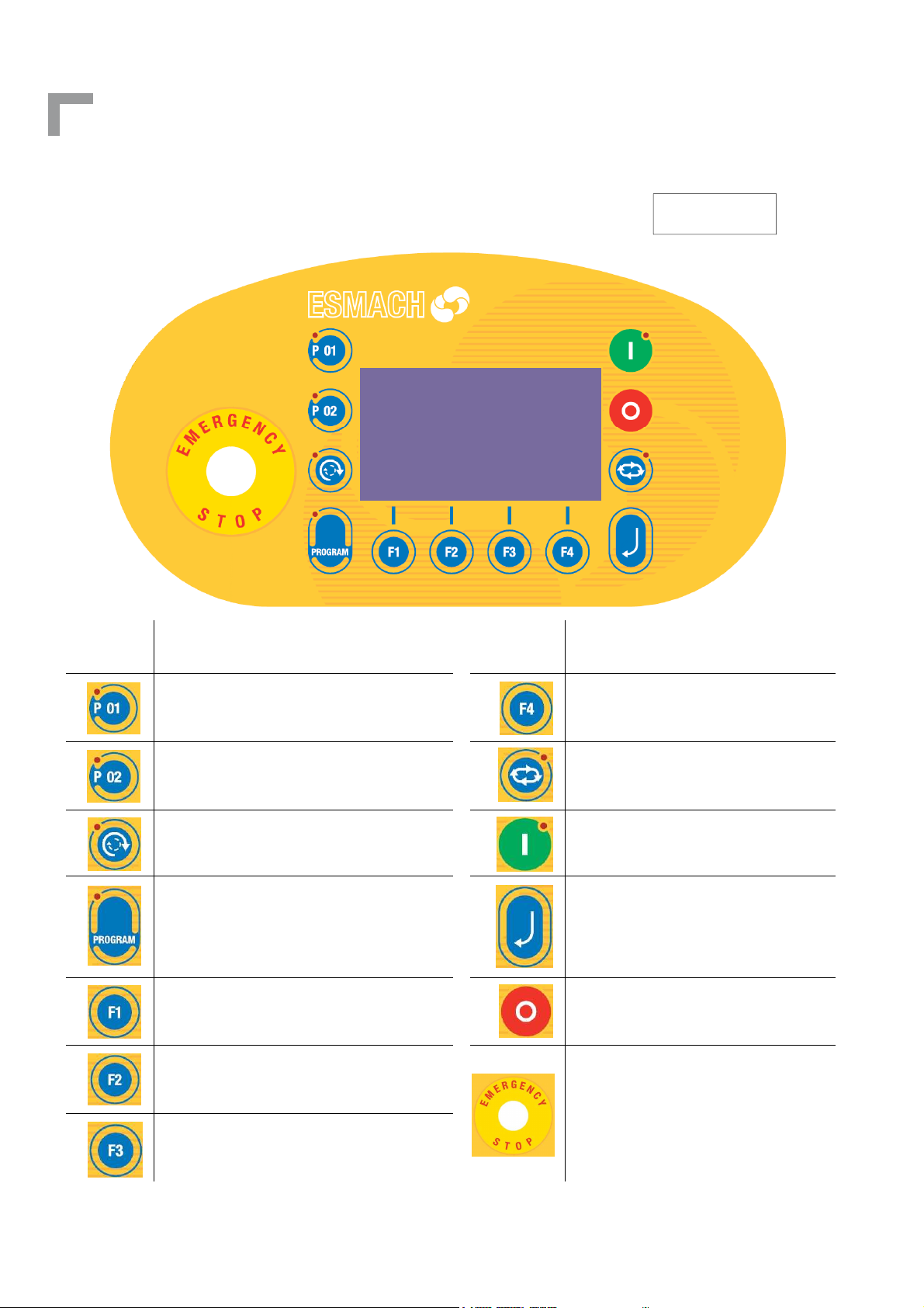
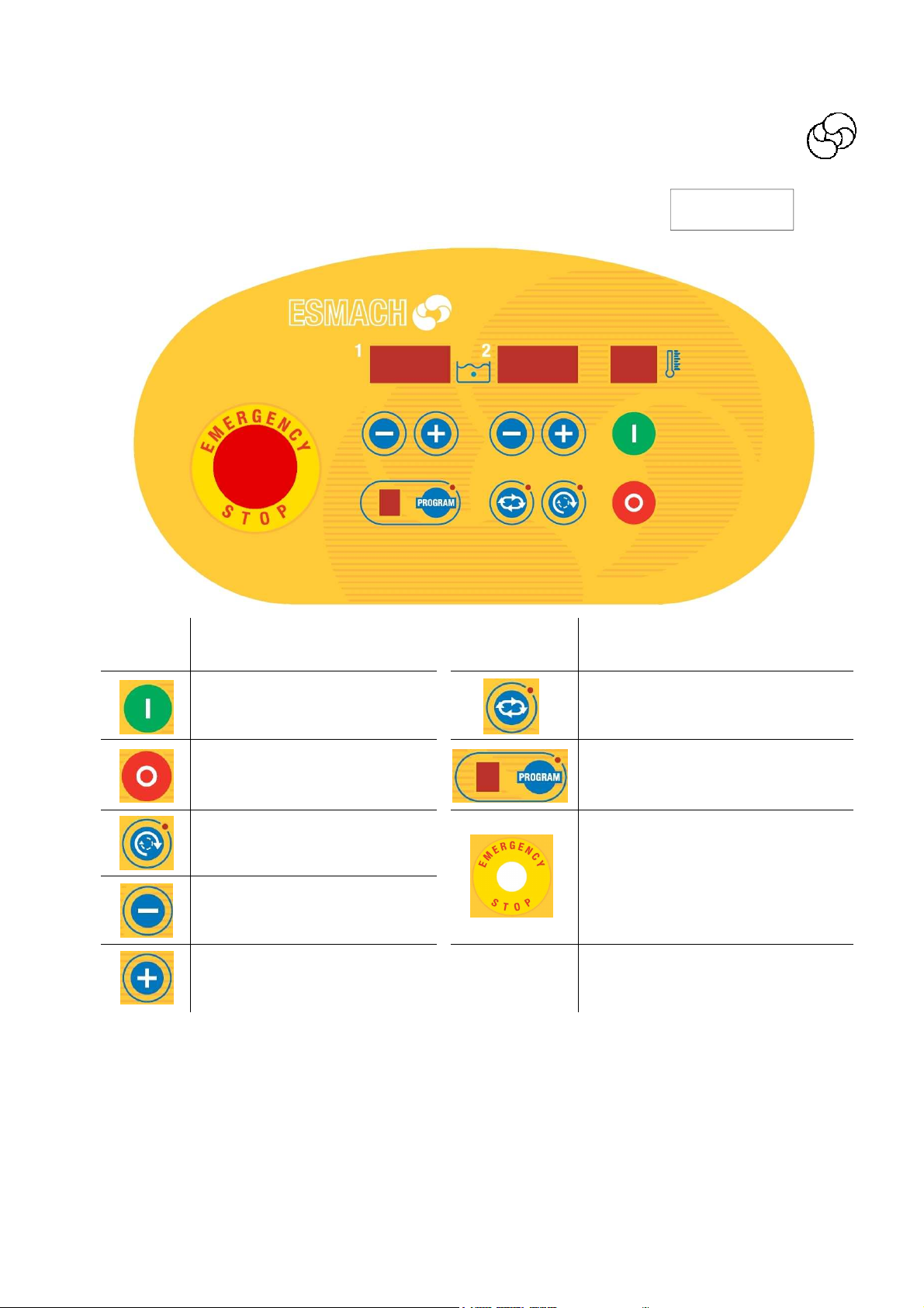
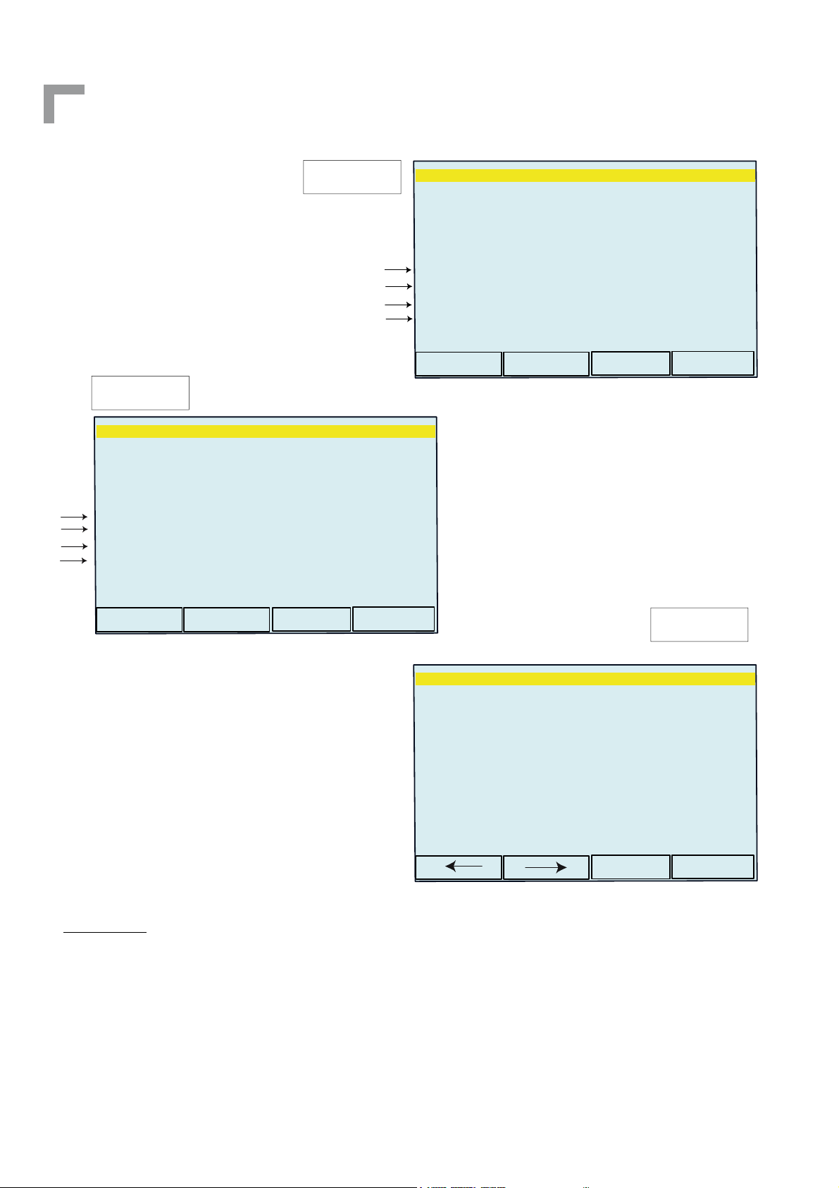
SYMBOLS ON CONTROL PANEL
“Advanced control panel”
Figure n° 7
SYMBOL DESCRIPTION SYMBOL DESCRIPTION
PROGRAMME QUICK RECALL KEY
PROGRAMME QUICK RECALL KEY
BOWL INVERSION
PROGRAMME KEY
FUNCTION KEY
AUTOMATIC/MANUAL CYCLE KEY
CYCLE START KEY
ENTER KEY
FUNCTION KEY
FUNCTION KEY
CYCLE STOP KEY
18
EMERGENCY BUTTON
FUNCTION KEY
Page 19
SYMBOLS ON CONTROL PANEL
“Simplified control panel”
Figure n° 8
English
SYMBOL DESCRIPTION SYMBOL DESCRIPTION
START CYCLE KEY
STOPO CYCLE KEY
BOWL INVERSION KEY
DECREASING KEY “DOWN”
INCREASING KEY “UP”
AUTOMATIC/MANUAL CYCLE KEY
PROGRAM SELECTION/PROGRAM
CONFIRMATION KEY
EMERGENCY PUSH BUTTON
SECTION B - POINT 1
TRANSPORT, HANDLING AND STORAGE
The weight and overall dimensions of the machine are given in Section A point 2. The machine is
shipped assembled and packed in a case/crate/pallet made of nailed wooden boards provided
with the symbols and indications for handling. The operators in charge of handling the load must
be qualified and adequately trained. Store the machine in a dry ventilated room and cover it
with a protective sheet.
will stabilize the machine.
19
Page 20
Instruction for use and maintenance
Spiral mixer with removable bowl SPI 160-300 A HYBRID
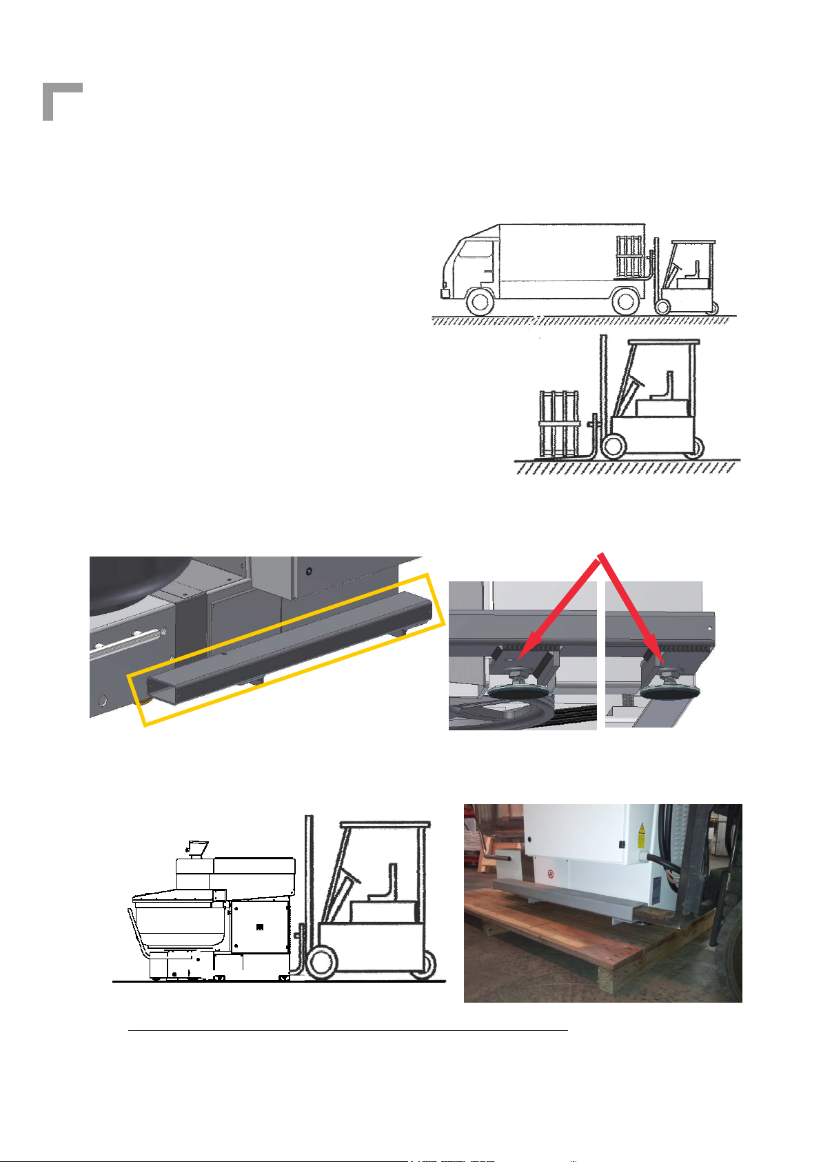
EXAMPLE OF MACHINE UNLOADING WITH FORKLIFT TRUCK
Stage 1: Unload the machine from the lorry in its
packaging;
Stage 2: Rest the machine on the ground;
Stage 3: Unpack the machine;
Stage 4: Make sure that the machine in its complex is in equilibrium .
Stage 5: Make sure that the brackets for lifting are properly inserted on the feet of the machine
and fixed with nuts of the same feet.
FIXING NUTS
BRACKET FOR
LIFTING
Stage 6: Lift the machine avoiding sudden movements.
Stage 7: Only after standing the machine DOWN in the desired position
, loosen the nuts on the
feet and remove the brackets from the side. The nuts will be fixed later when it will stabilize the
machine.
20
Page 21
English
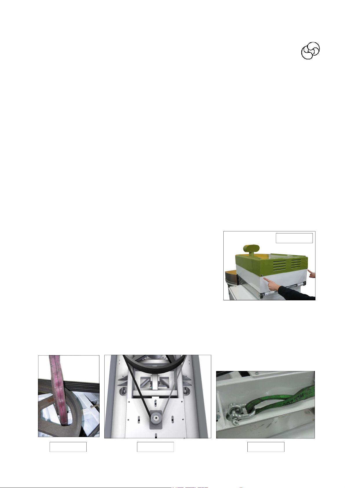
PROCEDURES FOR UNLOADING THE MACHINE USING A CRANE OR HOIST
Unloading personnel must be equipped with chains or ropes compatible with the weight and dimensions of the machine to be moved and in compliance with current safety regulations.
IMPORTANT WARNINGS !
- The slings must comply with ISO 4878 - ISO 9351 standards.
- Use the sling only if the label containing all the manufacturer information is affixed to it and
the capacity is clearly visible.
- Inspect the slings before all lifting operations. Do not use them if they are damaged, cut or
worn.
- Follow the load factors indicated for the various standardised configurations.
- Use adequate protection for lifting loads with sharp edges.
- Do not twist or knot the sling.
- Insert the other ends of the slings in the lifting equipment hook.
- Before moving the machine, ensure that there are no persons nearby.
- Carefully follow the unloading procedures described below.
1. remove the cover screws as per figure n°10
Figure n° 10
2. lift the rear cover
3. lean with care the cover
4. lift the machine:
- machine with jointed trolley : pass the belt in the front part of the central tube (Figure n°
11).
- pass the belts in the two eyebolts on the side of the head attached to the top of the col-
umn (Figures n ° 12 - 13).
Figure n° 11 Figure n° 12 Figure n° 13
21
Page 22
Instruction for use and maintenance
Spiral mixer with removable bowl SPI 160-300 A HYBRID
SECTION B – POINT 2
PREPARING THE ROOM - INSTALLING THE MACHINE
PREPARING THE ROOM
The room where the machine is installed and any existing equipment already installed in the
room must comply with the directives, regulations, standards and technical specifications etc. in
force in the user’s country (E.U. or EFTA).
INSTALLING THE MACHINE
The purchaser/user or his representative must check the condition of the machine upon unpacking, immediately notifying the manufacturer of any damage or defects encountered.
For installation of the machine, the specifications on the identification label illustrated in Section
A point 1 and the overall dimensions given in Section A point 2 should be taken into account. To
guarantee an optimal use of the machine it is necessary to follow the present installing procedure:
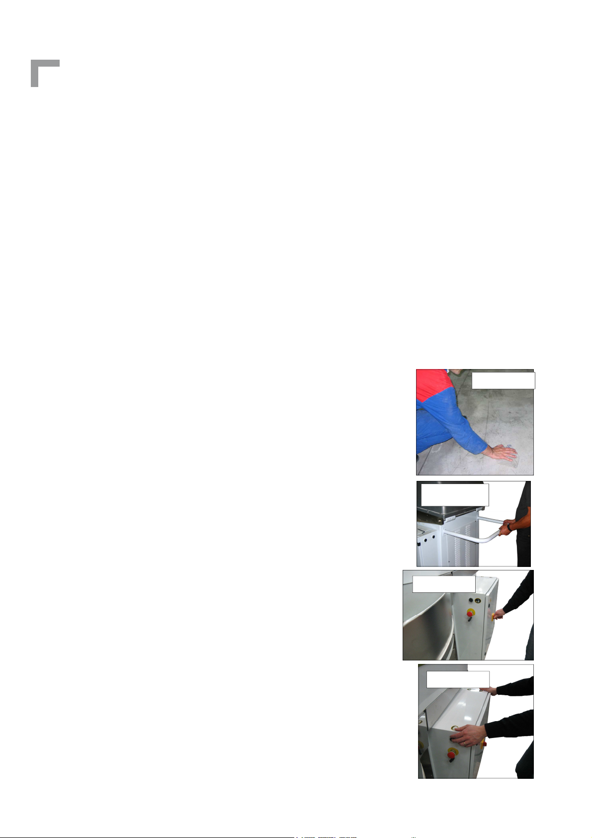
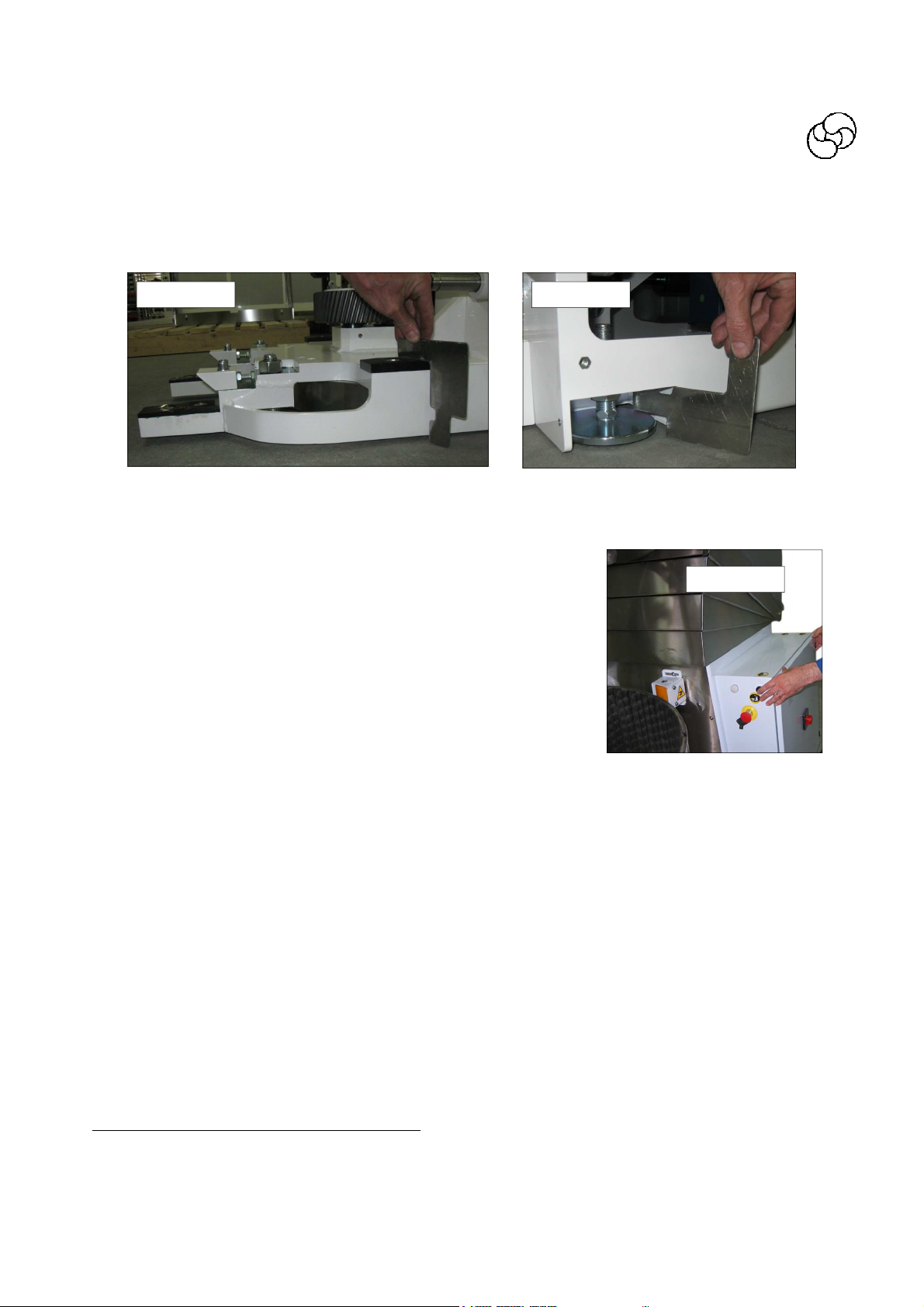
1. clean accurately the floor zone on which will be placed the machine so that the feet with anti-slide rubber have a better adhesion to the floor (figure n° 14)
2. Put the machine on the floor making sure there is an area of approximately 50 cm all around the machine for use and maintenance
3. fix the safety spacer tube (figure n°15) of the machine in the rear
zone in order to let the head raise automatically and avoid accidental crushing of the operators between the cover and the wall
under the machine
4. at this point switch on the machine (figure n° 16) following the
instructions as per Section B—Point 3
5. after having verified that all runs in the correct way, push contemporarily the common button and the button to lift the head
and unhook the trolley (figure n° 17)
Figure n° 15
Figure n° 16
Figure n° 17
Figure n° 14
22
Page 23
English
6. By means of the spacer (which is in the machine equipments) act on the feet in order to
carry the two chutes of the frontal rostrum at a right height from the floor (figure n°18-
19),
figure n° 18 figure n° 19
NB: it is indispensable that all feet are well fitted on the floor.
figure n°20
7. Put the trolley in the machine and hook it (figure n° 20)
8. Verify that the distance from the floor and the wheels under the trolley in the hooking
position is at least the thickness of a sheet of paper.
9. if the wheel touch the floor it must lift again the feet so that the wheels became free.
10.Now it must block the feet tightening nut with the key (equipment).
The machine is designed to operate in the normal temperature and humidity conditions found in
EU and EFTA countries.
The machine must not under any circumstances be used in places where there is the
danger of explosion or fire due to the presence or generation of dust, gas or explosive
or flammable mixtures.
For connection of the machine to the electrical power source, see points 4 and 5 of Section B.
NOTE: For connections in the US/Canada:
An electrician licensed under the jurisdiction (city, municipality, county, state, etc.) in which the
mixer will be installed must install the plug that meets requirements in sub-clauses 4.5.2.2 of
C22.2 No. 195 and 6.2.1, 11.1.1, 15.1.6 of UL 763.
23
Page 24

Instruction for use and maintenance
Spiral mixer with removable bowl SPI 160-300 A HYBRID
SECTION B – POINT 3
START-UP, USE AND ADJUSTMENTS
START-UP
One single trained and instructed operator is sufficient for use of the machine according to this
handbook.
IMPORTANT WARNINGS
Before starting the machine, follow the instructions below:
1. Check that the machine voltage, indicated in the identification label illustrated in Section
A, point 1, corresponds to the line voltage at the socket. If not, suspend the connection
operations and call the supplier or the manufacturer.
2. Turn the master switch to position 1. The display must be on. Make sure that the emergency buttons on the card and on the side of the electric box are not pressed. If the trolley is hooked and the head is lowered, press at the same time the common and upstroke
buttons (keys 3 and 6 as shown by the machine controls). When these two buttons are
pressed, the head lifts. This means that the pump turns correctly. If not, invert the
phases on the electrical plug.
24
Page 25
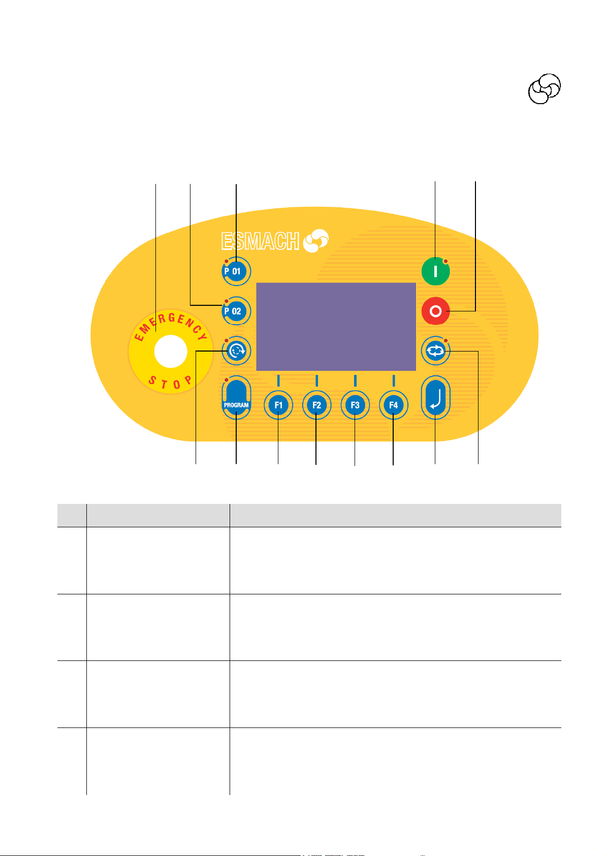
MACHINE CONTROLS:
“Advanced control panel”
English
Figure n°21
1 3 2
12 13
legend:
DESCRIPTION FUNCTION
1 EMERGENCY BUTTON
PROGRAMME QUICK RE-
2
PROGRAMME QUICK RE-
3
4 BOWL INVERSION
CALL KEY
CALL KEY
4 5 6
When it is pressed, it stops the machine and locks all possible
movements. Turn it clockwise to unlock the button.
Note: there are two emergency push buttons (ref. 17)
When it is pressed, it recalls the main programme n° 1
(without access to programming).
When it is pressed, it recalls the main programme n° 2
(without access to programming).
When it is pressed, it inverts the bowl motion (led on). Inversion is possible only when the spiral turns at low speed and not
in programming mode. (programs from10 to 99)
When it is pressed during recipe programming it insert the inversion phase
7
8
9
10 11
25
Page 26

Instruction for use and maintenance
Spiral mixer with removable bowl SPI 160-300 A HYBRID
DESCRIPTION FUNCTION
Pressing it one time you can recall the last program you set
up.
When it is pressed twice, it displays the list of all 99 recipes.
5 PROGRAMME KEY
After having selected the recipe, it is possible to start the
working cycle pressing the START key (if the situation allows
starting). During programming the led on the left of the key is
on.
6
7
8
9
FUNCTION KEY
F1
FUNCTION KEY
F2
FUNCTION KEY
F3
FUNCTION KEY
F4
10 ENTER KEY
The key can have different functions according to what the display shows.
The key function is displayed in the down line
The key can have different functions according to what the display shows.
The key function is displayed in the down line
The key can have different functions according to what the display shows.
The key function is displayed in the down line
The key can have different functions according to what the display shows.
The key function is displayed in the down line
It allows entering or exiting from recipe programming. For
these operations, the key has to be kept pressed for 3 seconds
until is displayed “insert code”.
AUTOMATIC/MANUAL
11
CYCLE KEY
12 CYCLE STOP KEY
13 CYCLE START KEY
26
It allows changing from manual cycle to automatic cycle. During the automatic cycle the led on the right of the key is on.
1-When it is pressed, it stops the machine. If pressed during
the machine running it allows the cycle stopping and times
memorization.
2-if pressed twice during the machine running, it allows the
machine stopping and the working times restoring.
When it is pressed, it starts the mixing cycle. The cycle can
starts only if the head is in work position and there is no emergency.
Page 27
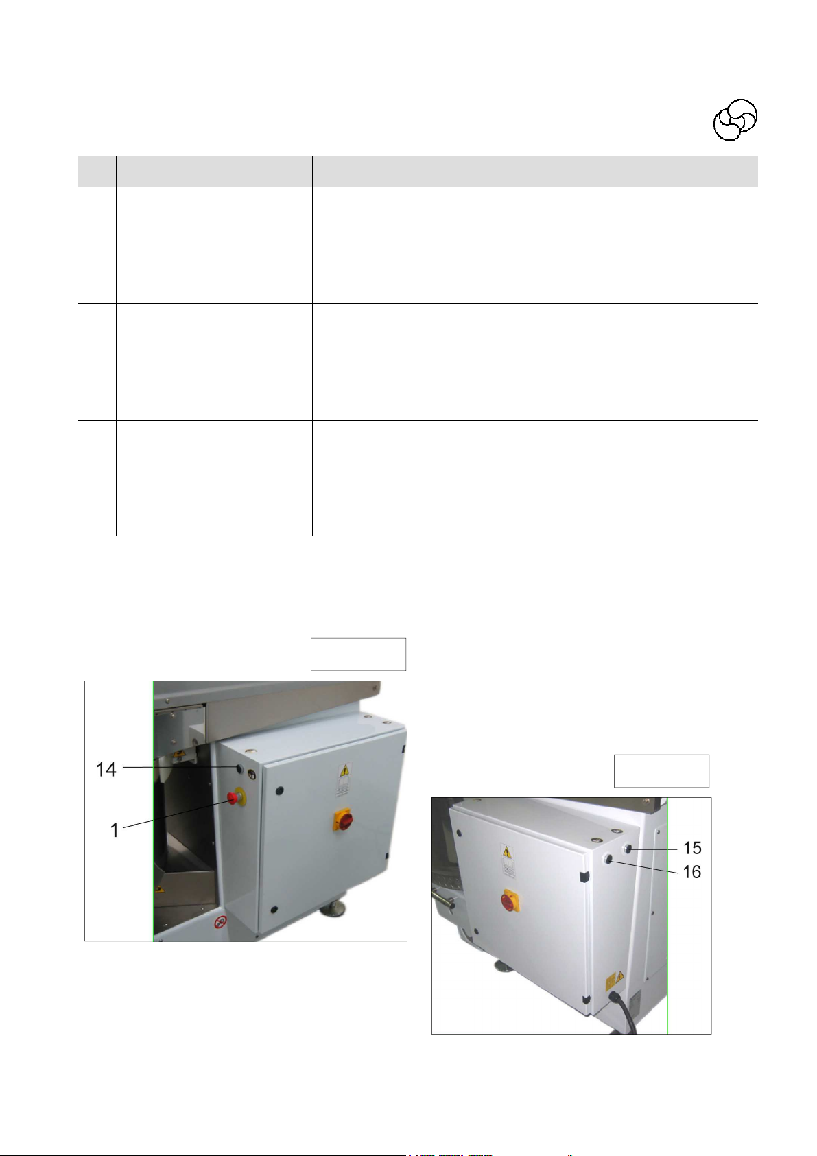
DESCRIPTION FUNCTION
Common button for trolley hooking/unhooking and head upstroke/downstroke. This button has to be pressed at the same
14
MACHINE HANDLING
COMMON BUTTON
time of the buttons 15-16.
When it is pressed alone for at least 0,5 sec. at upstroke head
without trolley, it allows the hook lowering to make easier the
trolley connection in case of not levelled floor.
English
HEAD UPSTROKE /
15
TROLLEY UNHOOKING
BUTTON
HEAD DOWNSTROKE /
16
TROLLEY HOOKING BUT-
TON
When it is pressed together with button 14, it allows to lift the
head and, once the head is lifted, to unhook the trolley.
If pressed together with the button 14, it hooks the trolley
and, at hooked trolley pressing the same buttons it allows the
head lower
Figure n°22
Figure n°23
27
Page 28

Instruction for use and maintenance
Spiral mixer with removable bowl SPI 160-300 A HYBRID
WORKING CYCLE START – AUTOMATIC WORKING
Trolley hooking / Head downstroke / Head upstroke / Trolley unhooking
To hook the trolley, place the trolley near the machine and follow the instructions below:
Press at the same time the buttons on the two sides of the box (common button “14” and downstroke button “16”)
When the trolley is hooked, the head begins to lower. Keep buttons pressed until the head has
gained the work position (head down). The trolley unhook is automatic only when the head is
completely upstroke.
All controls are of hands-on type.
If the floor has a slope opposite to the unit and the trolley into position goes away from the machine, it is possible to pre-hook the trolley by pressing the common key. “14” for at least 3 seconds.
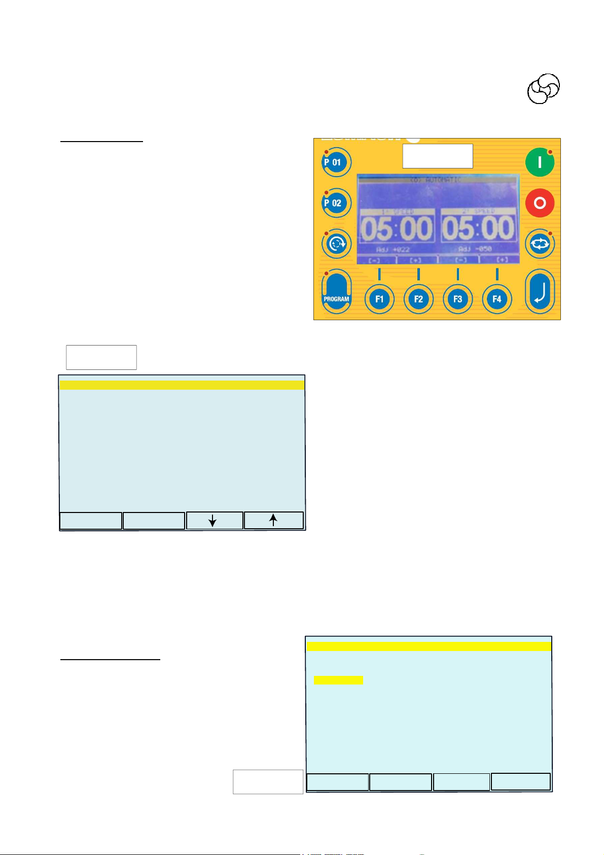
MANUAL CYCLE WORKING H (figure n° 24)
The manual cycle is available if key leds n°5 and 10 are off. Contrarily, touch over and over on
key “11” utill “MANUAL (H) “ appears.
When the START key 13 is pressed, the machine begins to work at the 1
The time on the 1
st
speed left timer increases.
During this phase it is possible to invert the bowl
direction by pressing the key 4.
The machine works at the 2
again the START key.
The machine can work at 2
minimum time in 1
utes) has been spent.
The time on the 2
st
speed (minimum 2 min-
nd
speed right timer increases.
The machine works at the 1
again the START key,
You can change the bowl speed at the 1
with the function keys F1-F2 (ADJ from +50-50).
You can change the bowl speed at the 2
nd
speed by pressing
nd
speed only if the
st
speed by pressing
st
speed
nd
speed
st
speed.
Figure n°24
with the function keys F3-F4 (ADJ from + 50-
50).
The machine stops by pressing the STOP key 12. The timer count is reset by pressing again the
STOP key.
AUTOMATIC CYCLE WORKING “0”
Press the key 11 to change from the programme MANUAL H to the programme AUTOMATIC 0.
The led must light on (figure n°30).
Set the working time at the 1
Set the working time at the 2
st
speed with the function keys F1-F2.
nd
speed with the function keys F3-F4.
Press the START key 13 to start the cycle.
If you press the ENTER key, the last line of the display shows the bowl speed variation at first
and second speed as already explained for THE MANUAL CYCLE.
If you do not press one of the keys F1-F2-F3-F4 within 3 seconds, with these buttons you do not
change the bowl speed but times are increased.
28
Page 29
RECIPES - LIST
It is possible to memory two kinds of recipes:
simple recipes: numbered from 1 to 9 in which
Figura n°25
it is possible to recorder the dough times, the
bowl speed and in case the automatic upstroke
recipes with variations: from n° 10 to n° 99,
in addition to the functions described in
point a), the following can be programmed and
stored: addition of salt, improver, temperature
control and raising of the head at the end of the
cycle (only if the machine is provided
with the relevant optionals).
Figure n°26
-05-
RECIPE N. 05
The names of the recipes are shown by pressing
the key PROG. With the keys F4-F3 you can select a new recipe.
SELECT RECIPE
05:RECIPE N.05
06:RECIPE N.06
07:RECIPE N.07
08:RECIPE N.08
09:RECIPE N.09
10:RECIPE N.10
11:RECIPE N.11
12:RECIPE N.12
Confirm by pressing the key F2.
Exit from the list of the recipes by using the key
F1. You go back to the previous recipe if you do
not confirm by pressing the key F2.
Start the work cycle by pressing the key START.
To recorder the automatic up-stroke at the end
of cycle in the simple recipes you must:
▪ push ENTER key
ESC
OK
▪ digit the programming access code “250”
confirming it with ENTER key.
▪ move in the proper box with F1/F2 keys
▪ select “yes” or “not” with key F3/F4 confirming than with ENTER.
▪ With “P01” and “P02” you can recall possible priority programs.
▪ To relate the program to the recipe see “list of parameter modifiable by the user”
RECIPES WORKING
-11 -
RECIPE N. 11
Press twice STOP key.
Press the key PROG: the led is on.
The last selected recipe is shown (figure n°
RECIPE
PHASES
PHASE NUMBER:04 TOTAL TIME : 05.30
27).
Figure n°27
NAME :RECIPE N.11
MAX TEMP. °C :25.2
TEMP. CONTROL :No
INSERT THE CODE : 255
TAB
EDIT
English
29
Page 30
Instruction for use and maintenance
Spiral mixer with removable bowl SPI 160-300 A HYBRID
Only if present on the machine,
the display shows the accessory
salt, improver, temperature
To enter in programming or modify a recipe press the key Enter “10” for 3 seconds.
The enter code is required. (figure n° 28).
Figure n°29
-11 -
PHSE NUMBER : 00 22°C
TOTAL TIME : 00.00
NAME : RICETTA N. 11
UP-STROKE : yes
T. SALT : 00.10
T. IMPROVER : 00.10
MAX. TEMP. °C : 25.2
TEMP. CONTROL : Si
F01 STOP :
INSERT THE CODE : 250
Now the cursor is on the first letter of recipe
name.
The keys F3-F4 let run through the character
The keys F1-F2 let move to the right or to the
left.
The F2 key lets go to the next phase (salt distribution, improver , upstroke ...):the distribution
time must be counted from the cycle end
(example: total kneading time =10 minutes;
salt distribution time: 3 minutes; the salt will be
distributed at the 7th minutes form the beginning of the cycle)
UP-STROKE
By setting “yes”, 10 seconds after the end of mixing, the head moves up automatically until
it reaches the raised position. The trolley is manually released. To release the trolley, simply
press the common buttons “18” and up button “19” for 0.5 seconds.
By setting “no”, at the end of mixing, the head must be raised manually by simultaneously
pressing the common buttons “18” and up button “19”.
RECIPE N. 11
Figure n°28
[-]
[+]
-11 -
PHASE NUMBER : 00 22°C
TOTAL TIME: 00.00
NAME : RICETTA N. 11
UP-STROKE : yes
T. SALT : 00.10
T. IMPROVER : 00,10
MAX. TEMP °C : 25.2
TEMP. CONTROL : si
F01 STOP :
Set the value 250 with the keys F3-F4
(figure n° 29) and confirm with Enter key.
-11-
PHASE NUMBER : 00 22°C
TOTAL TIME : 00.00
NAME : RICETTA N. 11
UPSTROKE : yes
T. SALT : 03.00
T. IMPROVER : 00.10
MAX. TEMP. °C : 25.20
TEMP. CONTROL : si
F01 STOP :
RECIPE MODIFICATION >Stop<TO EXIT
RECIPE N. 11
RECIPE N. 11
Figure n°30
[-]
[+]
30
Page 31

English
V-V1 adj + 037
Mixing TEMPERATURE (OPTIONAL)
The temperature value can be set only from recipe 10 to recipe 99.
To set the temperature, follow the procedure
below:
▪ press the ENTER key
▪ type in the code for “250” programming access and confirm via the
“ENTER” key
▪ move to the required field via keys F1/F2
▪ set the temperature value via keys F3/F4
▪ go to the next parameter via key F2
▪ use key F4 to enable the temperature control
during mixing (phase F01 is ignored)
▪ use key F3 to disable the control. In this case
the temperature value is displayed all the same.
If the operator activates the mixing temperature control, the machine stops when the set temperature is reached.
The operator can then decide whether to suspend or resume the work cycle by pressing the
STOP or START key.
WORKING PHASES: F01
The keys F1-F2 let move to the right or to the left.
Press the key F3-F4 to select the requested function.
Under the phase F01 it is possible to set:
-1
st
speed (bowl rotation in the same sense of
the spiral arm)
-bowl inversion (bowl rotation sense contrarily
to the spiral arm)
After function selection, press F2 key. The cursor goes to value area of the relative phase.
With F3-F4 keys set the time. To go to the next
phase press F2 key. To return to the previous
phase press F1 key.
Under the phase F02 it is possible to set:
▪ 1
st
speed
▪ bowl inversion
▪ 2
nd
speed
▪ stand-by
▪ stop
Press ENTER to confirm all recipe parameters.
The stop key let exit to the recipe programming without saving the datas.
If the machine is in working position press start key. Display will show the programm as per
figure n° 33
USER MODIFYABLE PARAMETERS: access code 111
To accede to user parameters, press PROG key for at least 3 seconds untill “insert the code” is
displaied.
Insert the code 111 by F3-F4 keys.
Conferm with F2 key.
Select the parameter by F3-F4 keys.
Set up the value with F1-F2 keys.
-11-
PHASE NUMBER : 04 22°C
TOTAL TIME : 11.45
MAX. TEMP. °C : 25.20
TEMP. CONTROL : si
F01 1° SPEED : 00.45
F02 BOWL INVERSION : 00.30
F03 1° SPEED : 02.15
F04 2° SPEED : 06.15
F05 STOP
-15-
Total : 02.30 Remaning : 02.28
TEMP. MAX. °C : 25.20
F01: 1st speed : 02.30
F02: STOP
02.26
RECIPE N. 11
RECIPE N. 15
RUN
Figure n°31
Figure n°32
-
+
31
Page 32

Instruction for use and maintenance
Spiral mixer with removable bowl SPI 160-300 A HYBRID
P01 Inversion exclusion P06 Recipe connected to P01 key
P02 Horne activated P07 Recipe connected to P02 key
P03 Bowl rotation sense P08 language
P04 Display contrast adjustment P09
P05 Display brightness adjustment
Press STOP key to exit programming.
PROGRAMS DISPLAY
The display shows the 1st and 2nd speed incremental time.
Switching from the 1st to the 2nd speed is performed by
(H) MANUAL
pressing the START key. To return to the 1st speed, press the
START key again.
Possibility of modifying the bowl speed.
The display shows the 1st and 2nd speed decremental time.
Switching from the 1st to the 2nd speed occurs when the 1st
bowl speed time expires.
(O) AUTOMATIC
Possibility of raising the head in automatic mode at the end of
the cycle.
Any modifications to the work times remain stored without
entering programming.
The display shows the 1st and 2nd speed incremental time.
Switching from the 1st to the 2nd speed occurs when the 1st
bowl speed time expires.
1÷9 RECIPES
Possibility of raising the head in automatic mode at the end of
the cycle.
Any modifications to the work times do not remain stored. To
store the times, enter programming.
The display shows:
▪ Work cycle total time
▪ Remaining time
▪ Phase in progress time
10÷99 RECIPES
▪ Phase in progress remaining time
▪ Head up at end of cycle
▪ Bowl speed /adj)
▪ Mixture temperature (*)
▪ Salt distribution time (*)
▪ Improver distribution time (*)
(*) only if provided on the machine (optionals)
32
Page 33

MACHINE CONTROLS:
“Symplified control panel EB”
English
Figure n°33
1 3 2
4
18
7
6 5
17
8 9
11 12 13 1 4
10
16
15
legend:
DESCRIPTION DESCRIPTION
1 EMERGENCY BUTTON 10 PROGRAMMING LED
2 1
ST
SPEED TIME DISPLAY 11 AUTOMATIC/MANUAL CYCLE KEY
3 1
st
SPEED TIME “UP” KEY 12 AUTOMATIC OPERATION LED
4 1
st
SPEED TIME “DOWN” KEY 13 13 BOWL INVERSION KEY (*)
5 2
nd
SPEED TIME DISPLAY 14 BOWL INVERSION LED
6 2
nd
SPEED TIME “UP” KEY 15 CYCLE START
7 2
nd
SPEED TIME “UP” KEY 16 CYCLE STOP
8 PROGRAM NUMBER. DISPLAY 17 TEMPERATURE PROBE DISPLAY
9 PROGRAM SELECTION/ 18
WATER DISPENSER LED
(only for spiral mixers SPI F)
33
Page 34

Instruction for use and maintenance
Spiral mixer with removable bowl SPI 160-300 A HYBRID
DESCRIPTION FUNCTION
Common button for trolley hooking/unhooking and head
upstroke/
downstroke. This button has to be pressed at the same
19 MACHINE HANDLING
HEAD UPSTROKE /
TROLLEY UNHOOKING
20
BUTTON
time of the buttons 19-20..
When it is pressed alone for at least 0,5 sec. at upstroke head
without trolley, it allows the hook lowering to make easier the
trolley connection in case of not levelled floor.
When it is pressed together with button 18, it allows to lift the
head and, once the head is lifted, to unhook the trolley.
HEAD DOWNSTROKE /
21
TROLLEY HOOKING
BUTTON
19
If pressed together with the button 18, it hooks the trolley
and, at hooked trolley pressing the same buttons it allows the
head lower
Figure n°34
Figure n°35
20
21
34
Page 35

English
WORKING CYCLE START – SPI Awith simplified control panel EB
Completely down stroke the machine head. On the machine keft side, the led near the emergency
push button must be on.
After this operation it is possible to programm the cart and push START.
MANUAL OPERATION
If the emergency button is not pressed, the haed is downstroke, the automatic key led is not on
and the machine is not working, “ooo ooo” will be shown on the 1st-2nd speed time display. The
program display will show -.
In addition to the emergency button, only the following keys are active:
- “start”
- “stop”
- “bowl-inversion” (also during operation)
Keys 9 “PRG programming” and 11 “automatic cycle” are not enabled.
Time Keys 3-6 “up” and 4-7 “down” are neither active nor enabled.
Led 12 on the “automatic cycle” key and the led on the “PRG” key are off.
The two “display-timers” are set to zero (000 000).
When key 15 “start” is pressed, the machine starts at first speed.
The first speed display indicates the operating time (incremental): up to 9’ and 50” it shows 2
digits for the seconds and 1 for the minutes; beyond this, it shows three digits for the minutes
(blinking dot to mark the seconds).
The program display 8 shows H.
With the machine operating only at first speed the “bowl-inversion” command is enabled.
When key 13 “bowl-inversion” is pressed, both the spiral arm and the bowl stop. After 1.5s the
movement is inverted. This interval is not calculated by the timer. (The same thing happens
when the key is pressed again and the inversion is de-activated).
The first speed display shows the time in incremental mode.
Whenever key 13 “bowl-inversion” is pressed, the first speed timer is temporarily blocked for the
time indicated above (1.5s).
If the bowl inversion function is enabled and the start key 15 is pressed twice, the machine operates
at minimum time at first speed with the bowl in reverse direction; it then operates for
1.5s with the bowl in normal direction and then switches to the 2
inversion function is automatically disabled. While the machine operates in 1
speed display blinks; this means that the machine switches automatically to 2
minimum operating time in 1
st
speed.
nd
speed. In this case the bowl
st
speed, the second
nd
speed after the
If the machine is operating in 1
to 2
nd
speed. Reaching of the 1
st
speed and button 15 “start” is pressed, the machine switches
st
speed minimum time (2 seconds or 2 minutes) must always be
guaranteed.
The 1
st
speed display stops at the time reached; the 2
nd
speed display indicates the operating
time (incremental).
If the machine is operating in 2
st
return to 1
speed (intermediate pause time between 2
nd
speed and the start key 15 is pressed again, the machine will
nd
and 1
st
time: 1.5s).
If the start key 15 is pressed again, the machine operates at 2
nd
speed.
All this is possible if the grille is not lifted or the stop key 16 is not pressed.
35
Page 36

Instruction for use and maintenance
Spiral mixer with removable bowl SPI 160-300 A HYBRID
If the stop key is pressed, the machine stops and the display-timers lock at the time reached up
to that moment.
If the “emergency button” is pressed, the machine stops and the display-timers show a code
that corresponds to the message “emergency pressed” (e.g. “---“ “---“).
When the mushroom-headed button is released, the display-timers show the time reached up to
that moment.
Opening the machine protection, the machine will stop and the display-timers will show the time
reached up to that moment, in blinking mode.
When the protection is closed, the display-timers show the time reached up to that moment (in
continuous non-intermittent mode).
In these last three conditions, since the timer that measures the 1
st
speed minimum time has
set to zero, we can have the following situations:
If the stop has occurred with the machine in 1
At the next start-up, it will resume operation in 1
st
speed:
st
speed from the moment when it was interrupted
until it completes at least the minimum time (2 seconds or 2 minutes).
Once the minimum operating time in 1
st
speed has been completed, you can switch to 2
nd
speed
by pressing the START button.
When the “stop” key is pressed, the display-timers go to zero and it is possible to start a new
cycle;
The START button can be pressed also during operation of the machine in 1
if the minimum time in 1
st
speed has not yet elapsed, the 2
nd
speed display will blink.
st
speed. In this case,
If the stop has occurred with the machine in 2
by pressing the “start” key it is possible to continue operation: the machine restarts in 1
for the duration of the minimum 1
2
nd
speed (in this case the 1
until the 1
st
speed minimum time is reached). When the machine switches to 2
st
st
speed time (2 seconds) and then switches automatically to
speed display-timer increments while the 2
nd
speed:
st
nd
speed display blinks
nd
speed, the time
speed
increments and the display stops blinking.
If the “stop” key is pressed only once, the display-timers lock. If the stop key is pressed a second
time, the displays go to zero and it is possible to start a new cycle.
If the maximum time of 99’5(9)” is reached, the machine stops.
AUTOMATIC OPERATION
The “automatic cycle” key is enabled exclusively with the machine at a standstill, not in the work
cycle (i.e. at the end of an automatic cycle or after interrupting a manual cycle by pressing the
“stop” key twice).
When the “automatic cycle” key is pressed, the red led comes on and the two displays show the
operating times set in the last automatic work cycle (the first time the machine is used,
the following default values are set by Esmach: 5’ in first speed, 8’ in second speed).
These values can be modified via the “up” and “down” keys (the increment/decrement is 15” up
to 9’59” and 1’ over 9’59”; if pressed for longer than 3s the scroll speed increases).
If the machine is provided with stainless steel grille bowl-protection it will not be possible to set
an operating time in first speed below 2’ (minimum time in first speed = 2’).
If the machine is provided with bowl-protection with ABS closed cover, it will not be possible to
set an operating time in first speed below 15” (minimum time in first speed = 15”).
36
Page 37

English
When the “start” key is pressed, the automatic cycle starts: the machine starts in first speed
and the display indicates the remaining operating time (decremental).
With the machine operating in first speed the “bowl-inversion” command is enabled.
When the related key is pressed, the red led comes on, the bowl stops and after a pause of 1.5s
the machine inverts the movement of the bowl. This interval is not calculated by the timer. The
same thing happens when the key is pressed again and the inversion is de-activated).
The first speed display shows the remaining time.
Whenever the “bowl-inversion” key is pressed, the first speed timer is temporarily locked for the
time indicated above (1.5s).
Once the time in first speed has elapsed, the machine switches automatically to second speed:
the first speed display remains set to zero while the second speed display begins to decrement.
During operation of the machine it is possible to modify the 1
st
and 2
nd
speed times with the following limits:
minimum time in 1
st
speed, i.e. if the min. time has already elapsed, the 1
st
speed time can be
zero-set but not otherwise;
the 1
st
and 2
nd
speed time cannot be modified simultaneously.
The modifications made during operation are not stored.
When the “stop” key is pressed, the machine stops and the display-timers lock at the time remaining up to that point.
When the machine is stopped in 1
st
speed, when restarted, it will resume operation in 1
st
speed
from the moment when it was interrupted until it completes at least the minimum time (2 seconds or 2 minutes).
Once the minimum operating time in 1
the 1
st
speed display you can set the time up to zero and switch to 2
remaining time in 1
st
speed after which the machine automatically switches to 2nd speed.
st
speed has been completed, via the “down” key below
nd
speed, or complete the
If the “emergency button” is pressed, the machine stops and the display-timers show a code
that corresponds to the message “emergency pressed” (“---“ “---“).
When the emergency button is released, the display-timers show the time remaining up to that
moment.
When the bowl-protection is raised with the machine operating, the machine stops and the
display timers show the time remaining up to that moment in blinking mode. When the protection is closed, the display-timers show the time remaining up to that moment (in continuous nonintermittent mode).
In these last three conditions, since the timer that measures the 1
st
speed minimum time has
set to zero, we can have the following situations:
If the stop has occurred with the machine in 1
by pressing the “start” key it is possible to continue operation; the machine restarts in 1
st
speed:
st
speed
(in this case the display-timers do not set to zero but continue to decrement the time).
By pressing the “stop” key, the display-timers return to the initial values and it is possible to
start a new cycle.
If the stop has occurred with the machine in 2
by pressing the “start” button it is possible to continue operation: the machine restarts in 1
speed for the duration of the 1
st
speed minimum time (2 seconds) (in this case the 1
display-timer is updated to the minimum operating time) and then switches automatically to 2
speed (once the minimum time in 1
st
speed has elapsed, it resumes decreasing the 2
nd
speed:
nd
speed
st
st
speed
nd
37
Page 38

Instruction for use and maintenance
Spiral mixer with removable bowl SPI 160-300 A HYBRID
display time);
At the end of the cycle, the mixing times are reset on the displays.
If the START button is pressed within 60 seconds from the end of the cycle, the machine restarts
in 1
st
speed and the time can be modified (via the “down” button below the 1
to zero. If the 1
st
speed time is set to zero, it is possible to switch to 2
nd
st
speed.
speed display) up
The second speed time can be modified as required (up to zero).
When the “stop” key is pressed, the display-timers go to zero and it is possible to start a new
cycle.
During the last 60s of operation in second speed (the machine signals the beginning of this
phase by emitting an acoustic signal) the 2
nd
speed display-timer shows the time remaining in
blinking mode (0.5s “on”, 0.5s “off”).
Once the time in second speed has elapsed, the machine automatically stops and an acoustic
signal sounds for 5s.
After the end of cycle acoustic signal, the display-timers show the initial values.
By pressing the “stop” key or the emergency button before the end of the acoustic signal, the
acoustic signal stops and the display-timers show the initial values.
In this condition, by pressing the “start” button, a new automatic cycle is started.
PROGRAMMING
Key 9 “PRG programming” is enabled exclusively with the machine at a standstill, not in the
work cycle (i.e. at the end of an automatic cycle or after interrupting a manual cycle by pressing
the “stop” key twice).
To enter “program-mode”, press the “PRG programming” key for at least 3s: the related red led
will come on and the display will blink.
In this condition it is possible to set the 1st and 2nd speed times by pressing the UP – DOWN
keys. To store these times the PRG key must be pressed again for 3s; the led will go out and the
program display will stop blinking.
If you enter programming, modify the times and then do not press any key, after 30s the
program display will stop blinking, the PRG key led will go out and the times will not be stored.
It is possible to use 10 programs (from 0 to 9).
By pressing the “PRG programming” key several times, it is possible to scroll the 10 programs
on the related display (the display-timers will consequently show the related stored times).
When the number corresponding to the required program is displayed, it is possible to start the
automatic operation cycle by pressing the “start” key.
If key 9 “PRG programming” is pressed for less than 3s, you go on to the next program (if the
start, stop or automatic cycle keys are pressed in this phase or if the operator does not touch
any key for 30s); the modified times are not stored in memory (the program-display stops blinking) and you return to the “program-mode”.
To quit the “program-mode”, press the “PRG programming” key for at least 3s: the related red
led will go out.
PROGRAM “0”
Unlike the other programs, program “0” allows you to set the times and store them without having to press key 9 PRG for 3s. The times can be stored in program “0” with the same logic as
programs 1 to 9.
The times can be modified even when the machine is operating but those set before the START
remain stored.
38
Page 39

English
BOWL-IMPULSES” COMMAND
With the machine at a standstill, not in the work cycle (i.e. at the end of an automatic cycle or
after interrupting a manual cycle by pressing the “stop” key twice) and the bowl protection open,
impulse rotation of the bowl can be commanded by pressing key 13 “bowl inversionimpulses”.
MACHINE WITH “INFRA-RED” MEASUREMENT DEVICE
The temperature measurement does not require any direct operation of the operator ( the device is permanently installed under the head of the machine and executes its function without
interruption). According to the value assigned to parameter P07 the following alternatives are
possible:
P07 = 0 = check the mixture temperature without stopping the cycle; if the temperature value
measured exceeds the value set up, an acoustic alarm is activated through flashing
and the display (17) blinks showing the value of the temperature every 4 seconds.
P07 = 1 = if the temperature value measured exceeds the value set up, this is detected through
the activation of a flashing acoustic alarm; the system controls the stop of the ongoing cycle and the display (17) blinks showing the value of the temperature every 4
seconds. The operator can allow the cycle to proceed by pressing the button START
(15) or cancelling it by pressing the button STOP (16).
P07 = 2 = the value of the temperature measured is displayed only (flashing) without any fur-
ther effect.
IMPORTANT REMARK: the acoustic alarm is activated the first time only when the
temperature measured exceeds the value set up in the program; for later exceedings,
no acoustic alarm is activated.
In MANUAL operating mode, the temperature is shown on the display (17) only and no value can
be set up for it.
HOW TO SET UP THE TEMPERATURE VALUE IN A PROGRAM
For each program ( from 0 to 9) a different temperature value can be set, but in the range between 0 °C and 65 °C (32 °F and 149 °F). To set and store the temperature value in a program,
proceed as follows:
-press repeatedly the button (9) until the program required is shown on the display (8)
-press the key PROGRAM (9) for about 3 seconds and keep it pressed until the led (10)
switches on and the display (8) starts blinking.
-press again the key (9) ( the display (19) blinks); set the temperature through the keys (3),
(4),(6),(7)
-if the machine has no ingredient dispenser systems, by pressing the key (9) for 3 seconds, it is
possible to go out from PROGRAMMING (the led (10) switches off and the display (8)stops
blinking), and the data are saved; otherwise switch to the programming of the 1° dispenser
If the set up temperature value has been exceeded, this may depend on the following :
a)machine not in operation: the display (17) blinks, showing the value of the temperature every
4 seconds
b)machine in operation: the display (17) blinks, as in case a), and ( only the first time when the
temperature value set exceeds, then no more) the acoustic alarm is activated for a time of 10
seconds.
The warning time is set up through the parameter P05
39
Page 40

Instruction for use and maintenance
Spiral mixer with removable bowl SPI 160-300 A HYBRID
USER’S PARAMETERS PROGRAMMING – CODE NO. 111
To reach the configuration “parameters set up” mentioned here below, do not press the emergency button (17), the led (12) is to be off and the machine not in operation.
On displays (2) and (5) the following “ooo” and “ooo” are to be shown.
Press and keep pressed at the same time the keys -/+ (3) - (4) - (6) - (7) for 4 seconds.
The display (2) shows “Cod” and the display (5) shows “000”
Through the keys +/- (3) and (4) set up on (5) the number 111; confirm it through the keys
(15) (see picture by side).
The display (2) shows the number of the parameter P01.
Through the keys +/- (6) e (7), the parameter is activated (ON) or deactivated (OFF) or the
value it to set up.
Through the keys +/- (3) and (4) the number of the parameter is changed progressively from
P01 to P19.
After the parameter set up, press the keys (16) to store the set up carried out and go out.
Descrizione parametro Opzioni
P01
Bowl reverse exclusion
OFF
Min
ON
ON
Max
Default Note
P02
Alarm activated
Bowl rotation direction for
P03
unload ( through lift only)
Activate sign from to 1st to
P04
nd
2
speed
Acoustic alarm operating
time to signalize:
-
switching from 1a to 2
speed (only if P04 = ON)
P05
-
exceeding of temperature
set up (for infra-red probe
machine only)
Temperature scale °C or °F
P06
Infra-red temperature measurement probe usage mo-
P07
de
ON
LH nor-
OFF
a
2 20 10
C F C
mal
direction
If this type of probe is present, the options are:
0 = mixture temperature control without stopping the cycle. Intermittent acoustic alarm if the temperature set up
exceeds.
0 2 2
1 = cycle stop through intermittent acoustic alarm while
exceeding the temperature set up. The operator proceeds
with the cycle by pressing the key (15) or terminates the
cycle by pressing the key (16).
2 = Display of the measured temperature only.
D1 dispenser time (seconds)
P08
40
2 120 30
Page 41

Descrizione parametro Opzioni
OFF
Min
ON
Max
Default Note
English
Default value “delay from the initial START ” (see Remark)
Default value “delay from the initial START ” (see Remark)
Set the value according to the mixture capacity of the
machine
If = 0 loads the values of P08 or P10
If > 0 loads the value set on P13 for both D1 and D2.
Advan-
Advan-
Delay Delay
ce
2 120 30
Delay Delay
ce
1 999 150
D1 dispenser mode
P09
D2 dispenser time (seconds)
P10
D2 dispenser mode
P11
Litre dispenser max. limit
P12
Acoustic alarm activation
P13
time (seconds) for D1 or D2
dispenser
P14 - - -
0 sec 30 sec 5 sec
Remark.
Delay = the distribution begins once the dispenser time set up has elapsed after the start
Advance = the distribution begins when the dispenser time set up is missing to reach the end of the cycle
41
Page 42

Instruction for use and maintenance
Spiral mixer with removable bowl SPI 160-300 A HYBRID
ADDITIONAL MANUAL CONTROLS
Only for special version mixers with additional manual controls.
Figure n°36
1
3
4
2
Figure n°37
3
4
2
42
Page 43

DESCRIPTION FUNCTION
When the selector is in position AUTO, the electronic card can
AUTOMATIC WORKING
1
operate. When the selector is in MANUAL position, working is
possible in manual mode. Attention: the selector can be
moved to the right (MANUAL) only when the card fails.
English
TROLLEY HOOKING/
UNHOOKING
2
HEAD UPSTROKE/
DOWNSTROKE
MANUAL WORKING AT
3
ST
1
SPEED
When the selector is turned DOWN BELOW (fig. A), it hooks or
unhooks the trolley.
When the selector is turned UP ABOVE (fig. B), it lifts or lowers
the head.
Attention: before making the head lower, the trolley has to be
hooked correctly
When the selector 1 is in HAND position and the 1st SPEED
button is pressed, the machine works at the 1
st
speed for an
indeterminate time. If you want to change the speed, press
both the emergency button near the box and the speed button
you prefer.
Attention: make sure the trolley is hooked correctly and the
head is in work position.
nd
SPEED
speed for an
MANUAL WORKING AT
4
2
ND
SPEED
When the selector 1 is in HAND position and the 2
button is pressed, the machine works at the 2
nd
indeterminate time. If you want to change the speed, press
both the emergency button near the box and the speed button
you prefer.
WORKING CYCLE START – MANUAL WORKING
If the electronic card fails, the machine can work in manual mode “HAND”.
Cut off the electrical power supply to the machine in order to open the electric box. Move the
selector 1 to the MANUAL position. Close the electric box and give electrical power supply to the
machine by turning the master switch.
If the trolley is unhooked, put the selector 2 turned DOWN BELOW in position A and hook the
trolley by pressing at the same time the buttons on the two sides of the box (common button
and downstroke button). When the trolley is hooked, keep buttons pressed for 3 seconds to
guarantee the tightness.
To lower the head, put the selector 2 turned UP ABOVE in position B and hook the trolley by
pressing at the same time the buttons on the two sides of the box (common button and downstroke button). When the head is lowered, keep buttons pressed for 3 seconds to guarantee the
tightness.
Attention: before lowering the head, hook the trolley correctly.
To make the machine work at the 1st speed, press the button 3 1st SPEED. The machine works at
the 1st speed for an indeterminate time. If you want to make the machine work at the 2nd speed,
press the emergency button near the box and press the button 4 2nd SPEED.
To open the head, put the selector 2 turned UP ABOVE in position B and press at the same time
the buttons on the two sides of the box (common button and upstroke button). When the head
is up, to unhook the trolley, put the selector 2 turned DOWN BELOW in position A and press at
the same time the buttons on the two sides of the box (common button and upstroke button).
43
Page 44

Instruction for use and maintenance
Spiral mixer with removable bowl SPI 160-300 A HYBRID
SECTION B – POINT 4
TROUBLESHOOTING
For troubleshooting and ordinary repairs, refer to the table below:
PROBLEM POSSIBLE CAUSE POSSIBLE SOLUTION
The bowl has an irregular operation during work.
The bowl wobbles badly during
operation.
The spiral arm slows down during mixing.
By pushing the upstroke and
down stroke keys the machine
doesn’t run but the hydraulic
unit motor is operating.
There is voltage on the power
board but the panel display
does not come on.
Drive belts loose. Tension the belt correctly.
Check that the play between
bowl and sliding block is 2-3
mm.
Adjust the distance between
rollers and replace them if
necessary.
Drive belts loose. Tension the belt correctly.
Motor turns in the opposite
direction.
Uncoupled solenoid connector.
Oil lack in the circuit.
No tension to the solenoid connector.
Solenoid failed.
Inverse the phases.
Check that all solenoid connectors are correctly connected.
Verify that the oil level on the
circuit tank is at list to ¾.
Replace the connector or its
the solenoid.
Check that the 5-pole green
connector is correctly inserted
in the board.
Check that the 9-pole connec-
Check the connectors.
tor between board and panel
and base board is correctly
inserted.
This connector is near the
head up/down microswitches.
The machine does not perform
some functions (carriage connection-release, head updown).
After trolley hooking, the head
downstroke but stop before
completing the stroke (complete
closure).
The oil unit motor stops.
If the trolley is not released after the ascent of the head.
If pressing start the machine
does not move after the descent
of the head.
44
Board.
Microswitch SQ4.
Microswitch SQ3.
Microswitch SQ4.
Turn the machine master
switch to the zero position
(OFF) and after five seconds
re-set to position one (ON).
Check if microswitch SQ4 is
pressed ( machine rear under
head cover).
Micro must be free only when
head is completely downstroke
(closed) and in working
position.
Verify if the microswitch SQ3
working properly.
Verify if the microswitch SQ4
working properly.
Page 45

PROBLEM POSSIBLE CAUSE POSSIBLE SOLUTION
When the buttons common
“14” and ascent “15” are
pressed, the head does not
move up.
When the buttons common
“14” and descent “16” are
pressed, the head does not
move down and the display
shows “EXTRACT THE TROLLEY
AND REPEAT THE COUPLING
ERR:17”.
When the buttons common
“14” and descent “16” are
pressed, the head does not
move down and the display
shows “EXTRACT THE TROLLEY
AND REPEAT THE COUPLING
ERR:18”.
Switch for up head.
Solenoid valve connectors engine control unit.
The input of the microswitch
SQ1 is not present.
The input of the microswitch
SQ2 is not present.
English
Verify the functionality of the
switch SQ3.
Make sure the connectors are
properly inserted and solenoid
valves that work.
Check the contact unit motor.
Verify the mounting and operation of the microswitch SQ1.
The micro must be pressed
when there is the trolley.
Verify the mounting and operation of the microswitch SQ2.
The micro mustn’t be pressed
when there is the trolley.
The display shows “CHECK
GRID LIMIT SWITCH”.
The machine stops during work
and display shows “VERIFY INVERTER”.
The machine stops during work
and the display shows “ERRORLINK”.
If the display shows “EXTRACT
THE TROLLEY AND REPEAT THE
COUPLING ERR:19”.
Bowl protection grid microswitch.
Inverter overcharged Inverter
failing.
Connector.
Sheath.
Motherboards.
Pressing the
“common”+“descent” buttons
when the trolley is not present
or is not resting on the hook.
The inputs of the microswitches SQ1-SQ2 are not
present.
Check the grid microswitches.
Switch off the machine.
After 15 s switch it on again: if
the problem still exist, call the
AFTER SALE SERVICE.
Verify on yhe inverter the last
alarm message.
Verify connection between
panel card and display.:
-1
st
connector CN6 on card to
relay
-2
nd
connector on panel card
-3
rd
intermediate connector under the head cover.
Switch off and than switch on
the machine.
If the problem still exit call the
after sale service.
Check that the sheath and conductors within it are not damaged.
Verify the microswitches.
45
Page 46

Instruction for use and maintenance
Spiral mixer with removable bowl SPI 160-300 A HYBRID
PROBLEM POSSIBLE CAUSE POSSIBLE SOLUTION
The display shows the message
“ACTIVE EMERGENCY PUSH
BUTTON”.
If the display shows “VERIFY
THE MAGNETOTHERMAL INTERVENTION”.
If the display shows “HEAD
OUT OF POSITION - LOWER
THE HEAD”.
If the display shows “HEAD
OUT OF POSITION”.
If the display shows “VERIFY
SQ1-SQ2 END STROKE”.
If the display shows “VERIFY
THE TEMPERATURE PROBE”.
Emergency button pressed.
When a circuit breaker trips
inside the electrical panel.
When the head is completely
closed and the power supply
is interrupted.
When pressing START button
in an intermediate position of
the head.
Working time at "0".
Pressing START when the trolley is not completely hooked.
When the temperature probe
is present and the mixture
exceeds the set temperature
set.
Check and turn to the right to
release the button.
Check which breaker is tripped
and reset it.
Move up the head a few inches
and then proceed with the descent.
Complete closure of the head
before pressing start.
Verify that the time is not at
"0" (excluding program H)
Press the related buttons and
move down the head.
Complete the coupling of the
trolley and the closure of the
head before press START.
Check the temperature of the
dough and the set value. Check
the probe.
46
Figure n°38 Figure n°39
SQ1 SQ2
SQ3
SQ4
Page 47

English
SECTION B – POINT 5
FOOD HYGIENE AND CLEANING
The machine has been designed and built according to the specifications of the EEC machinery
directive 89/392 (point 2.1).
The following machine cleaning instructions are provided for the user.
CAUTION: DO NOT USE HIGH PRESSURE WATER JETS
Once a day:
Clean the bowl, column, tool, dough guard and bowl protection. These are the stainless steel
elements (or thermoformed in the case of the transparent cover) in the food area. Use the tool
provided (plastic spatula) and clean with a cloth soaked in water. Never use metal tools and/or
abrasive products.
Once a week:
Clean the painted parts with lukewarm water (max 40°C). Never use metal tools and/or abrasive
products.
Once a year:
General cleaning of the machine according to the above instructions.
SECTION B – POINT 6
MAINTENANCE AND CHECKS
FOR CORRECT OPERATION AND LONG LIFE OF YOUR MIXER, FOLLOW THE ORDINARY AND SPECIAL MAINTENANCE PROGRAMME BELOW.
IMPORTANT WARNINGS!
All maintenance work must be performed after setting the master switch to 0 (zero) and removing the plug from the electrical power supply socket interlocked with switch.
This means:
- Do not clean, oil or grease by hand the moving parts and elements of the machine.
- Do not carry out any operation, repair or adjustment on moving parts.
The manufacturer accepts no liability for injury to persons or damage to things resulting from
failure to observe these instructions, tampering with the protections and safety devices fitted on
the machine and/or inappropriate use of the machine.
47
Page 48

Instruction for use and maintenance
Spiral mixer with removable bowl SPI 160-300 A HYBRID
MAINTENANCE TO BE PERFORMED BY THE OPERATOR
These operations and checks are very simple and can therefore be performed by the user, following the instructions below.
Once a day:
Check the efficiency of the protections and safety devices by operating and inspecting them.
MAINTENANCE TO BE PERFORMED BY SERVICE PERSONNEL AUTHORISED BY THE
MANUFACTURER
Due to their delicate and complex nature, these operations and checks must be performed by
the manufacturer or qualified/specialist personnel.
Once a month:
Check the efficiency of the safety devices
Check the condition and positioning of the bowl guide rollers (instructions follow)
Once every six months:
Adjust the spiral arm drive belt tension (instructions follows)
Adjust the bowl drive belt tension (instructions follows)
Check the electrical equipment
Check that the tool is correctly fixed
Check possible sliding of the moving wheel (corrective instructions follow)
check the hydraulic unit oil level (it must be at least ¾ of the tank)
It is good to periodically lubricate the mechanisms of movement of the trolley through the grease nipples. Two grease nipples are located in the front of the trolley close to the two front rollers
and two are accessing from the two holes in the side of the trolley and lubricate the two rear rollers (Figure 40).
48
Figure n°40
Page 49

English
It is a good idea to grease the pinion referral using the spe-
Figura n°41
cial grease gun indicated by the arrow (Figure 41).
Once a year
Perform general checks on the condition and efficiency of the machine, the protections and
safety devices.
Replace worn parts and/or broken elements if necessary.
Perform electrical tests to check the electrical insulation and continuity tests on the protection
circuit.
When necessary
Replace worn parts and/or broken elements, check and adjust the protections and safety devices. The power supply cable must be replaced if the outer insulation is damaged.
Caution: original parts must be used when replacing components.
CAUTION!
Cut off the electrical power supply before carrying out work
on any electrical component
or on the control panel.
ADJUSTING THE BOWL GUIDE ROLLERS/SLIDING BLOCKS
problem: the bowl wobbles badly
solution: adjust the bowl guide rollers in order to have a distance of mm 2-3 between the bowl
and the rollers (figure n° 42, 43)
Figure n° 42
Figure n° 43
49
Page 50

Instruction for use and maintenance
Spiral mixer with removable bowl SPI 160-300 A HYBRID
SPIRAL ARM TRANSMISSION BELT TENSION
problem: when mixing hard dough the spiral arm slow down
solution: adjust the tension of the spiral arm transmission belts in this way:
1. remove the rear head cover.
2. unscrew the screws securing the motor plate (Figure n° 42)
3. adjust the belts tensions acting on the screw placed frontally to the motor plate support
(figure n° 43); (to verify the correct belt tension press strongly on it: its movement
must be about of 5 mm)
4. refit all screws
Figure n° 44
Figure n° 45
BOWL TRANSMISSION BELT TENSION
problem: when mixing hard dough the bowl slow down
solution: tighten the belts which drive the bowl.
1. remove the rear cover of the column.
2. adjust the belt tension by turning the screw on the rear of the plate that supports the
engine (Figure N° 46).
Figure n° 46
ADJUSTMENT SCREW
50
REAR CARTER
Page 51

English
CHANGING GEAR (Figure 47-48-49-50-51)
problem: The gear does not allow a regular transmission because it’s worn.
solution: This gear was constructed in special self-lubricating material that reduces noise and
vibration boring. Pulling the trolley, as is seen at the center of the base.
Periodically check if the teeth are worn. If replacement is necessary, proceed as follows:
1. Remove the rear cover of the column.
2. Loosen the belt tension by turning the screw on the rear of the plate that supports the engine (Figure N° 46).
3. Lift the spiral mixer.
4. Remove the belt from the pulley and remove the lateral covers (Figure N° 47).
5. Unscrew the 8 screws that secure the inside front (Figure N° 48-49).
6. Extract all the front group.
7. Remove the cover with a screwdriver.
8. Unscrew the central screw and remove the complete gear.
9. Unscrew the 6 screws of the cover.
10. Pull gear.
11. Replace gear.
12. Reassemble everything.
WARNING: in the case of total replacement of the gear simply unscrew the central screw and
pull the whole thing.
Figure n° 47
Figure n° 48 Figure n° 49
4
5
51
Page 52

Instruction for use and maintenance
Spiral mixer with removable bowl SPI 160-300 A HYBRID
7
Figure n° 50
8
9
10
Figure n° 51
52
Page 53

English
53
Page 54

Instruction for use and maintenance
Spiral mixer with removable bowl SPI 160-300 A HYBRID
SECTION B - POINT 7
REPLACING WORN PARTS
For reasons of safety it is essential to read and observe the IMPORTANT WARNINGS given below
before carrying out any work.
IMPORTANT WARNINGS !
These operations must be performed by specialist expert personnel provided by the manufacturer or authorised qualified service centres.
Before performing any operation, remove the plug from the electrical power supply socket interlocked with switch.
SECTION C - POINT 1
EMERGENCIES
If the machine is used correctly, emergencies cannot occur during operation or during cleaning
and maintenance on condition that the latter are performed according to the instructions provided in this manual.
In the event of imminent mechanical danger, press the emergency button and remove the plug
from the current socket interlocked with switch. This must be followed by identification of the
failure or fault that caused the danger and restoring of machine operation and protections. If
necessary, request the assistance of the manufacturer’s technical support service or competent
personnel.
If current leakage is found upon contact with metal parts of the machine, immediately remove
the plug from the current socket, interlocked with switch, and call an electrician or the
manufacturer’s technical support service.
SECTION C - POINT 2
DECOMMISSIONING – SCRAPPING
DECOMMISSIONING
If the machine has to be “temporarily” decommissioned for any reason, it must be unplugged
from the socket, interlocked with switch, cleaned as described in Section B, point 5 and covered
to protect it from dust.
For re-commissioning, follow the commissioning instructions (see Section B, point 3).
SCRAPPING
At the end of its working life, the machine must be removed and withdrawn by the manufacturer
or dealer. If the user wishes to perform scrapping himself, he should remember that various materials
are involved such as metals of various types, rubber, plastic, oil etc. which must be disposed
of in compliance with regulations for industrial and special waste, i.e. by delivering the
above materials, suitably selected, to specialist environment-friendly disposal firms.
54
Page 55

Page 56

Instruction for use and maintenance
Spiral mixer with removable bowl SPI 160-300 A HYBRID
56
Page 57

Français
Page 58

Page 59

TABLE DES MATIERES
Page
Présentation, avertissements généraux et conditions de garantie 61
1.Données d’identification de la machine 62
2.Caractéristiques techniques 63
3.Usage 64
SECTION A 4.Description de la machine 64
5.Mesures de prévention contre les risques pour la sécurité et la santé64
6.Signaux de sécurité - Symboles 67
1.Transport, manutention et emmagasinage 71
2.Amenagement des locaux - Installation de la machine 73
3.Mise en fonction, utilisation et réglage 75
SECTION B 4.Irrégularités de fonctionnement et solutions possibles 94
5.Hygiène alimentaire et nettoyage 97
6.Maintenance et contrôles 97
7.Substitution pièces usées 104
SECTION C 1.Situation de secours 104
2.Mise hors service, démolition 104
Français
INDEX ALPHABETIQUE
Amenagement locaux 74
Avertissements généraux 61
Caractéristiques techniques 63
Conditions de garantie 62
Démolition 104
Description de la machine 65
Données d’identification de la machine 65
Fiche de maintenance 103
Hygiène alimentaire et nettoyage 97
Installation de la machine 74
Irrégularités de fonctionnement et solutions possibles 94
Manutention de l’opérateur 98
Manutention et contrôles 98
Manutention par le Service Après-vente de la Société constructrice 98
Mesures de prévention contre les risques de nature électrique 67
Mesures de prévention contre les risques de nature mécanique 66
Mesures de prévention contre les risques dus au bruit 67
Mesures de prévention contre les risques pour la sécurité et la santé 65
Mesures de prévention contre l’hinalation de poussière de farine 67
Mesures de prévention pour l’hygiène 67
Mise en fonction 76
Mise hors service 104
Présentation 61
Signaux de sécurité 68
Situation de secours 104
Substitution pièces usées 104
Symboles 68
Transport 72
Usage 65
Utilisation 76
59
Page 60

Page 61

Français
PRESENTATION, AVERTISSEMENTS GENERAUX, CONDITIONS DE GARANTIE
PRESENTATION
Cette notice d’instructions a été réalisée et structurée pour permettre une consultation rapide
et simple. Dans ce but, la PRESENTATION et les AVERTISSEMENTS GENERAUX ont été
enrichis par un INDEX PAR ARGUMENT et un INDEX ALPHABETIQUE.
Pour chaque argument traité, de nombreux dessins et tableaux illustrent des textes
correspondants et simplifient la lecture et la compréhension.
Cette notice d’instructions est divisée en SECTIONS.
Pour connaître les arguments traités par chaque section, consultez l’INDEX PAR ARGUMENT.
AVERTISSEMENTS GENERAUX
Cette notice d’instructions s’adresse au propriétaire/utilisateur de la machine, au personnel de
direction, au personnel chargé de la manutention, installation, utilisation, surveillance,
entretien et démontage de la machine.
Cette notice fournit les informations sur les caractéristiques techniques et l’utilisation de la
machine, les instructions/indications/informations pour sa manutention et son installation,
pour son montage, réglage et utilisation ainsi que les informations nécessaires pour
l’instruction du personnel pour diriger les interventions de maintenance, simplifier la
recherche des défaillances, commander les pièces de rechange, localiser les risques résiduels,
etc.
Cette notice est partie intégrante de la MACHINE DESTINEE A L’USAGE PROFESSIONNEL et,
comme telle, il ne pourra jamais remplacé ni une préparation adéquate, ni l’expérience de
l’utilisateur. Dans cette notice on a mis en évidence les opérations qui doivent être effectuées
par du personnel spécialisé.
La société constructrice rappelle que la Clientèle qui utilise cette machine doit également
respecter les normes spécifiques relatives aux lieux de travail et souligne que la conformité
des lieux de travail constitue une condition indispensable pour une correcte installation et
utilisation de la machine.
Cette notice doit être considérée comme partie de la machine et doit être conservée comme
référence future jusqu’au démontage de la machine même.
De plus, elle doit être rangée dans un endroit sec, d’accès facile et si possible près de la
machine.
La société constructrice se réserve le droit de mettre à jour la machine et les notices
d’instructions, sans aucune obligation de mettre à jour les machines et les notices
d’instructions réalisées précédemment, sauf en cas exceptionnel. Toutefois, la société
constructrice se met à disposition des Clients, qui en feront demande, pour transmettre toute
ultérieure information nécessaire.
En cas de cession de la machine, la société constructrice conseille à la Clientèle de lui
communiquer le nom et l’adresse du nouveau propriétaire pour permettre toute
communication entre le fabricant et l’utilisateur.
La société constructrice décline toute responsabilité en cas de:
a. utilisation impropre de la machine ou manipulation de la part de personnel non
spécialisé pour l’emploi de machines professionnelles
b. utilisation contraire aux normes nationales spécifiques
c. installation incorrecte
d. défauts d’alimentation
61
Page 62

Notice d’utilisation et de maintenance
Pétrin à cuve extraible SPI 160-300 A HYBRID
e. non respect des opérations de maintenance prévues
f. modifications ou interventions non autorisées
g. utilisation de pièces détachées non originales ou non spécifiques pour le modèle de
machine
h. non respect total ou partiel des instructions
i. faits exceptionnels, etc.
CONDITIONS DE GARANTIES
La machine est garantie pour une durée de 12 mois consécutifs à partir de la date d’achat, si
on respecte les instructions contenues dans cette notice. La garantie s’interrompt si la machine a été utilisée sans respecter ces instructions ou si la machine a été dépannée, démontée
ou modifiée par des techniciens ou des Services Après-vente non autorisés. En cas de dommages causés par l’emploi incorrect de la machine, toutes les parties électriques seront exclues de la garantie.
SECTION A - POINT 1
DONNEES D’IDENTIFICATION DE LA MACHINE
La figure n° 1 reproduit la plaquette qui a été appliquée sur la machine à l’endroit indiqué par
la flèche sur la figure n° 2. La plaquette contient toutes les données nécessaires à
l’identification de la machine.
Figure n° 1
62
Figure n° 2
Page 63

Français
SECTION A - POINT 2
CARACTERISTIQUES TECHNIQUES
Les caractéristiques techniques principales de la machine sont indiquées sur la figure n° 2 et
dans les tableaux A et B qui suivent.
Figure n° 3
Sens de rotation de la cuve
(vue du dessus): sens
contraire des aiguilles d’une
montre
SPI A Hybrid 160 200 250 300
A mm 1656 1656 1654 1654
B mm 832 892 857 937
C mm 900 900 1045 1045
D mm 1862 1833 1954 1913
E mm 1127 1127 1200 1200
F mm 1860 1860 1983 1983
63
Page 64

Notice d’utilisation et de maintenance
Pétrin à cuve extraible SPI 160-300 A HYBRID
DATI TECNICI 160 200 250 300
Capacità max impasto kg 160 200 250 300
Capacità max di farina kg 100 125 150 185
Capacità totale litres 250 300 360 430
Velocità spirale 50 Hz(*)
Velocità vasca 50 Hz (*)
Velocità spirale 60 Hz(*)
Velocità vasca 60 Hz (*)
r.p.m.
r.p.m.
r.p.m.
r.p.m.
86-172 86-172 86-172 86-172
9-18 9-18 10-20 10-20
103-206 103-206 103-206 103-206
10.8-21.6 10.8-21.6 12-24 12-24
Potenza per 50Hz kW 10,1 10,1 12,9 12,9
Potenza per 60Hz kW 12,9 12,9 15,1 15,1
Volume imballo m3 4,4 4,4 4,4 4,4
Peso netto dell macchina kg 1210 1220 1370 1380
(*) valeurs indicatives
64
Page 65

Français
SECTION A - POINT 3
USAGE
Le pétrin à spirale, est destiné exclusivement au pétrissage de farine pour la boulangerie et
pâtisserie, et d’autres produits alimentaires cuits au four
auxquels on peut ajouter différents ingrédients comme le sucre, la graisse, le sel, l’eau, la
levure, etc., et destinés aux ateliers et magasins d’alimentation. La variété des ingrédients à
pétrir est très vaste. L’opération complète est normalement formée de plusieurs cycles de
durée différente.
Tout autre usages éventuel doit être considéré comme dangereux pour l’opérateur et pour la
conservation de la machine. De même, les modalités d’installation et/ou d’utilisation de la
machine diverses de celles indiquées dans la Section B, points 2 et 3, peuvent causer des
dommages à l’opérateur et à la machine.
SECTION A - POINT 4
DESCRIPTION DE LA MACHINE
La machine est formée essentiellement par:
▪ une structure fixe avec
- sur le côté le tableau électrique et les dispositifs pour le
déplacement
- à l’intérieur tous les organes pour:
- le soulèvement de la tête
- l’accrochage du chariot
- la transmission de la cuve
▪ tête mobile attachée à la structure fixe équipée de:
- l’ustensile de pétrissage
Figure n° 4
- une barre qui garantit une meilleure oxygénation de la
pâte
- tous les organes de transmission de l’ustensile de pétrissage
- un tableau de commande électronique sur la partie antérieure
▪ un chariot qui peut être décroché de la machine avec:
- la cuve pour contenir les ingrédients.
- tous les organes d’accrochage à la structure centrale
Caractéristiques générales:
▪
niveau de pression acoustique continu équivalent pondéré A ≤ à 70 dB (A).
▪
La machine, dans l’ensemble, a un degré de protection IP 44.
Attention
La Section B point 3 contient des détails supplémentaires avec les illustrations
correspondantes.
Attenzione
Altri particolari della macchina con le relative illustrazioni sono riportati nella Sezione B punto 3.
SECTION A - POINT 5
MESURES DE PREVENTION CONTRE LES RISQUES POUR LA SECURITE ET LA SANTE
La société constructrice a construit et projeté la machine en tenant compte des résultats d’une analyse attentive et soignée des risques POUR LA SECURITE ET LA SANTE liés à l’utilisa-
65
Page 66

Notice d’utilisation et de maintenance
Pétrin à cuve extraible SPI 160-300 A HYBRID
tion de la machine.
Les protections et les dispositifs de sécurité installés sur la machine sont donc le résultat d’un
engagement considérable de la part du constructeur pour garantir au maximum, dans le cadre de l’état de l’art, les normes de sécurité sanctionnées par les directives CEE spécifiques.
arguments seront repris dans les points spécifiques qui concernent l’UTILISATION, la MANUTENTION, le DEPANNAGE, etc.
la machine est conforme:
à la Directive 98/37 CEE
à LA Directive CEM 89/336 CEE
à la Directive BT 73/23 CEE
à la norme de produit en 453 du Août 1999 où sont rappelées les normes générales applicables.
La machine est conforme à la législation en vigueur au moment de la livraison: il appartient
à l’utilisateur d’adapter son matériel à l’évolution des normes, auquel cas celui-ci à la responsabilité de demander au fabricant si il y a nécessité de la faire.
MESURES DE PREVENTION CONTRE LES RISQUES DE NATURE MECANIQUES
5
VOLUME INTERESSE PAR L’USTENSILE EN MOUVEMENT
(zone 1-figure n° 5)
la cuve est recouverte par une grille en inox solidaire
1
avec la tête sur la partie antérieure et par une plaque
anti-éclaboussures en inox sur la partie arrière.
L’ouverture de la tête et de la grille fixée à celle-ci, est
temporisée comme indiqué dans la norme de produit
EN453 pour que l’ustensile s’arrête dans les 4 secondes
qui suivent l’ouverture de la tête.
ESPACE ENTRE LA CUVE ET LA STRUCTURE (zone 2figure n° 5)
3
Conforme à la norme de produit EN453
MECANISME POUR LE DEPLACEMENT VERS L’AVANT DE LA CUVE (zone 3-figure n° 5)
Organes en mouvement signalées par des étiquettes indiquant le danger et qui encouragent à
maintenir les distances de sûreté
MECANISME DE MISE EN ROUTE, POSITIONNEMENT (zone 4– figure n° 5)
Tous les déplacements de la machine s’effectuent grâce à des boutons à pression maintenue
(double boutons poussoir) qui empêchent risques à l’opérateur.
NB: toutefois l’opérateur doit contrôler qu’il n’y ait personne autour de la machine.
L’accès à tous les organes de la machine pour la maintenance, l’inspection et le nettoyage
peut être effectué en enlevant les carters de protection à l’aide d’une clé spécifique fournie en
dotation avec la machine.
ROULEAUX GUIDE CUVE (zone 5-figure n° 5)
Les rouleaux guide cuve sont protégés par des protections fixes conformément à al norme de
Figura n° 5
4
2
66
Page 67

Français
produit EN453.
MESURES DE PREVENTION CONTRE LES RISQUES ENGENDRES PAR LE BRUIT
La machine fonctionnant à vide, condition estimée comme la plus défavorable, émet un
niveau de pression acoustique continu équivalent pondéré A ≤ 70 dB (A).
La machine ne produit donc aucun bruit, nuisible ou qui contraigne à l’utilisation de casque
ou bouchons.
STABILITE
Le pétrin est muni de pieds de mise à niveau automatique équipés de caoutchouc antiglisse.
En positionnant correctement les pieds (comme indiqué dans la section spécifique) la machine devient stable et ne nécessite d’aucun ancrage au sol.
MESURES DE PREVENTION CONTRE LES RISQUES DE NATURE ELECTRIQUE
Contre le danger dérivant des contacts directs et indirects, on a adopté les mesures de
prévention prévues par la norme EN 60204-1 et on a effectué tous les tests prévus par la dite
norme, comme indiqué dans l’annexe à la déclaration de conformité CE. De plus, on a
effectué les tests prévus par les normes techniques en vigueur pour le respect de la directive
CEE sur la compatibilité électromagnétique EMC.
MESURES DE PREVENTION POUR L’HYGIENE
On met en évidence, en particulier, que:
A. Les éléments ou les parties de la machine (cuve, utensiles, barre et protection de la cuve)
destinés à entrer en contact avec les produits alimentaires qui forment la pâte ou qui font
partie de la dite ZONE ALIMENTAIRE sont en ACIER INOX (la protection cuve peut être en
méthacrylate thermoformé approprié pour le contact alimentaire).
B. Les éléments ou les parties de la machine qui peuvent entrer en contact avec les produits
alimentaires indiqués ci-dessus dans la dite ZONE SALISSANTE OU D’ECLABOUSSURES
sont en ACIER INOX ou en ACIER VERNI AU FOUR.
C. La machine est conformes aux principes de conception pour assurer l’aptitude au nettoyage
selon la norme EN 453.
Mesures de prevention pour l’inhalation de poussière de farine
La farine est un élément pussiereux qui peut nuir à la santé (affections respiratoires) et doit
etre manipulée de manière de limiter le plus possible la présence de poussières de farine à
l’intérieur des locaux.
Si la machine est munie de protection cuve avec grille en inox, pour limiter la production de
poussières de farine, le temps de fonctionnement en première vitesse ne peut pas être programmé à une valeur inférieure à 120 secondes (réf. EN 453).
Voici d'autres avertissements utiles aux opérateurs qui manipulent régulièrement l'farine
67
Page 68

Notice d’utilisation et de maintenance
Pétrin à cuve extraible SPI 160-300 A HYBRID
La farine, l'élément principal utilisé dans les premiers stades de la pâte, est considéré comme le principal élément dans le secteur de la boulangerie qui provoque des maladies respiratoires telles que la
rhinite et l'asthme.
En fait, la poussière émise lors de la manipulation de la farine crée réactions
dans le câble qui créent des problèmes respiratoires moins graves qui les diverses formes de rhinite ou
tels que les diverses formes de l'asthme sévère.
Voici quelques conseils pour limiter autant que possible la présence de poussières de farine
dans l'enceinte au cours de la préparation de la phase de suspension et la même phase de la pâte:
1. utiliser des sacs de 25 kg au lieu de 50 kg et vider les sacs plusieurs fois
2. supporter l'extrémité ouverte du sac dans le fond de la cuve de mélange et le soulever avec
tirant doucement à partir de l'autre extrémité
3. limiter autant que possible la hauteur de chute de la farine
4. pas fortement secouer le sac vide et fermez-le, puis incorporer délicatement le ou rouler
5. ajouter la farine dans l'eau (et non l'inverse);
6. répandre la farine à la main ou avec le tamis, sans jeter
7. nettoyer la surface de travail avec la racle utilisée pour couper la pâte, et non à l'aide d'outils
souffleurs (soufflet ou soufflets);
8. garder les vêtements de travail distincts de civil
9. Ne secouez pas, ni brosser les vêtements de travail, mais les laver;
10. éviter les courants
11. est très important de réduire la vitesse d'action de la console, en particulier dans les premiers stades
(5 premières minutes), lors de la farine et de l'eau ne sont pas encore suffisamment mélangés et partie
de farine tout usage est encore humide
12. réduire la vitesse après chaque addition de farine
13. l'utilisation de l'aspirateur avec filtre d'aspiration élevée et les opérations effectuées à l'aide d'humide
grattoir sont préférables à l'utilisation des brosses à main de plumeaux
14. porter un masque de protection pendant le chargement manuel
D'autres substances, telles pulverolenta peuvent être nocifs ou dangereux pour la santé, consultent
à cet égard, les données techniques du fournisseur.
SECTION A - POINT 6
SIGNAUX DE SECURITE - SYMBOLES
Les signaux de sécurité sont indiqués sur la machine grâce à des autocollants spécifiques qui
attirent l’attention de l’utilisateur sur les éventuels dangers possibles et sauvegardent celui-ci
en termes de sécurité.
Contrôler que les couleurs et les
inscriptions qui se trouvent sur les
signaux et les s ymboles s oient
parfaitement conservés. Au moindre
signe de détérioration, les remplacer, en
les demandant au fournisseur ou à la
B
Figura n° 6
H
D
C
F
E
68
A
G
Page 69

REF. SYMBOLE DESCRIPTION
Français
A
B
C
D
E
NE PAS ENLEVER LES DISPOSITIFS DE SECURITE
ATTENTION—DANGER D’ECRASEMENT
DANGER – ELEMENTS SOUS TENSION
VOLTAGE
MISE A TERRE
F
G
H
PE
SENS DE ROTATION CUVE ET USTENSILE
BORNE DU CONDUCTEUR DE PROTECTION EXTERNE
ATTENTION – LIRE LA NOTICE D’INSTRUCTIONS
69
Page 70

Notice d’utilisation et de maintenance
Pétrin à cuve extraible SPI 160-300 A HYBRID
SYMBOLES DU TABLEAU DE COMMANDE
“Panneau de commande avancé”
Figure n° 7
SYMBOLE DESCRIPTION SYMBOLE DESCRIPTION
TOUCHE RAPPEL VITESSE
PROGRAMME
TOUCHE RAPPEL VITESSE
PROGRAMME
INVERSION CUVE
TOUCHE PROGRAMME
TOUCHE FONCTION
TOUCHE CYCLE AUTOMATIQUE/
MANUEL
TOUCHE DEPART CYCLE
TOUCHE D’ENVOI
TOUCHE FONCTION
TOUCHE ARRET CYCLE
TOUCHE FONCTION
BOUTON POUSSOIR COUPP DE
POING
TOUCHE FONCTION
70
Page 71

SYMBOLES DU TABLEAU DE COMMANDE
“Panneau de commande simplifiée”
Figure n° 8
Français
SYMBOLE DESCRIPTION SYMBOLE DESCRIPTION
TOUCHE DEPART CYCLE
TOUCHE ARRET CYCLE
TOUCHE CYCLE AUTOMATIQUE/
MANUEL
SÉLECTION DU PROGRAMME /
PROGRAMME TOUCHE DE CONFIRMATION
INVERSION CUVE
BOUTON POUSSOIR COUPP DE
POING
TOUCHE “DOWN” TEMPS
TOUCHE “UP” TEMPS
SECTION B - POINT 1
TRANSPORT, MANUTENTION ET STOCKAGE
Nous rappelons que la valeur de la masse de la machine et les dimensions d’encombrement de
la machine est indiquée dans la Section A, point 2.
La machine est livrée, assemblée et emballée dans une caisse/cage/palette formée de planches
en bois clouées et sur lesquelles sont indiqués les symboles et les indications pour sa
manutention. Les opérateurs chargés de la manutention de la machine devront être spécialisé et
instruits de façon adéquate.
Pour le stockage de la machine, utiliser des locaux secs et aérés et protéger la machine avec une
bâche.
71
Page 72

Notice d’utilisation et de maintenance
Pétrin à cuve extraible SPI 160-300 A HYBRID
EXEMPLE DE PROCEDURE DE DECHARGEMENT DE LA MACHINE A L’AIDE D’UN CHARIOT ELEVATEUR
Phase 1: décharger du camion la machine encore
emballée;
Phase 2: déposer la machine sur le sol;
Phase 3: déballer la machine;
Phase 4: s’assurer que l’ensemble de la machine soit en équilibre;
Phase 5: Assurez-vous que les supports pour broches de levage sont correctement insérés sur la
machine et fixés avec des écrous des mêmes pieds;
ECROUS DE FIXATION
SUPPORT POUR
LEVAGE
Phase 6: Soulevez la machine, en évitant les mouvements brusques et soudains;
Phase 7: Seulement après avoir mis la machine sur le sol a la position souhaitée
, desserrer les
écrous sur les pieds et tirez les supports latéraux. Les dés seront fixées plus tard quand il sera
de stabiliser la machine.
72
Page 73

Français
DEPLACEMENT AU MOYEN DE CORDES DE SOULEVEMENT
Le personnel chargé des manœuvres devra se prémunir de chaînes ou de cordes, en vérifiant que
leurs caractéristiques soient compatibles avec le poids et les dimensions de la machine à déplacer et qu’elles soient conformes aux normes de sécurité en vigueur.
AVERTISSEMENTS IMPORTANTS !
- Les tirants à courroie doivent être conformes à la normative ISO 4878 - ISO 9351.
- Utiliser la courroie uniquement si l’étiquette, indiquant toutes les données de la Maison
Constructrice, est fixée sur celle-ci et la portée est indiquée clairement.
- Inspecter les courroies avant chaque soulèvement. Ne pas les utiliser si elles sont endommagées, coupées ou si elles présentent des signes d’usure.
- Suivre les facteurs de charge indiqués pour les différentes configurations standardisées.
- Utiliser des protections adéquates pour le soulèvement des charges avec des arêtes tranchantes.
- Ne pas entortiller ou faire des nœuds avec la courroie.
- Insérer les autres extrémités des tirants à courroie sur le crochet du moyen de soulèvement.
- Avant de déplacer la machine, vérifier qu’il n’y ait personne aux alentours.
- Suivre rigoureusement les procédures de déchargement indiquées ci-dessous.
1. dévisser les vis, qui se trouvent sur les côtés de la tête et
qui fixent le couvercle (Figure n° 10)
2. soulever la tête sur la partie arrière.
3. poser soigneusement le couvercle
4. soulever la machine:
- Machine à chariot articulé: passer la bande dans la partie avant du tube central (Figure n °
11).
- Passer les ceintures dans les deux anneaux de levage sur le côté de la tête fixée sur le haut
de la colonne (Figures n ° 12 - 13).
Figura n° 10
Figure n° 11 Figure n° 12 Figure n° 134
73
Page 74

Notice d’utilisation et de maintenance
Pétrin à cuve extraible SPI 160-300 A HYBRID
SECTION B - POINT 2
AMENAGEMENT DES LOCAUX – INSTALLATION DE LA MACHINE
AMENAGEME
Les locaux dans lesquels la machine sera installée, y-compris les différentes installations qui y
existent, devront respecter les directives, les normes, les spécifications techniques, etc. en
vigueur dans les différents Pays faisant partie de l’UE et de l’EFTA.
NT DES LOCAUX
INSTALLATION DE LA MACHINE
L'acheteur /utilisateur ou son représentant est prié de vérifier l’intégrité de la machine au moment du déballage en signalant immédiatement à la Maison Constructrice les éventuels dommages ou inconvénients remarqués.
Pour l’installation de la machine, il faudra tout d’abord tenir compte des données indiquées sur la
plaquette signalétique illustrée dans la Section A, point 1 et des mesures d’encombrement indiquées dans la Section A, point 2.:Pour garantir un excellent usage de la machine il est nécessaire de suivre la procédure d’installation suivante
1. nettoyer soigneusement la zone du plancher où sera installée la
machine pour que les pieds d’appui, munis de caoutchouc antiglisse, adhèrent mieux au sol (figure n° 14)
2. poser la machine sur le sol en ayant soin de laisser un espace
libre d’environ 50 cm tout autour de celle-ci pour faciliter le passage pendant l’usage et la maintenance
3. fixer le tube entretoise de sécurité, dont est munie la machine,
dans la zone arrière (figure n° 15),
4. Mettre en marche la machine (figure n° 16) selon les indications de la SECTION B – POINT 3
5. après avoir contrôler toutes les fonctions de la machine, appuyer
simultanément sur la touche commune et sur la touche de montée pour soulever la tête et décrocher le chariot si présent (figure
n° 17) en utilisant l’entretoise en dotation avec la machine
Figure n° 15
Figure n° 16
Figure n° 17
Figure n° 14
74
Page 75

Français
6. En utilisant l’entretoise en dotation, régler les pieds pour placer les deux glissières qui
se trouvent a une bonne hauteur à partir du sol (figure n ° 18-19),
figure n° 18 figure n° 19
NB: Il est très important que les 6 pieds soient bien posés sur le sol.
figure n°20
7. insérer le chariot dans la machine et l’accrocher (figure n°
20)
8. Vérifiez que la distance entre le sol et les roues sous le chariot dans la position d'accrochage est au moins l'épaisseur d'une feuille de papier.
9. si les roues posent sur le sol, il est nécessaire de soulever encore les pieds pour que les
roues soient libres
10. Maintenant, il faut bloquer les pieds de serrer l'écrou avec la clé (équipement).
La machine fonctionne dans les conditions de température normales et d’humidité qui caractérise les régions de UE et de l'EFTA.
Il est absolument interdit d’utiliser la machine dans des lieux où il existe des risques
réels d’explosion ou d’incendie à cause de la présence ou de la production de
poussières, gaz ou mélanges explosifs ou inflammables.
Pour le branchement de la machine à la source d’énergie électrique, voir Section B, points 4 et
5.
NOTE: Pour les connexions aux US/Canada:
Un électricien agréé sous la juridiction (ville, municipalité, département, région, etc)
dans laquelle le mélangeur sera installé doit installer la prise électrique qui répond aux exigences des sous-alinéas 4.5.2.2 de C22.2 no 195 et 6.2. 1, 11.1.1, 15.1.6 de la norme UL 763.
75
Page 76

Notice d’utilisation et de maintenance
Pétrin à cuve extraible SPI 160-300 A HYBRID
SECTION B - POINT 3
MISE EN FONCTION, UTILISATION ET REGLAGE
Pour faire fonctionner la machine, il suffit d’un seul opérateur qualifié et instruit au préalable.
AVERTISSEMENTS IMPORTANTS !
Avant de mettre en route la machine, suivre les instructions suivantes:
1. vérifier que le voltage de la machine, indiqué sur la plaquette signalétique illustrée dans
la Section A point 1 corresponde à la tension de ligne de la prise d’utilisation. Si ce n’est
pas le cas, ne pas effectuer le branchement électrique et appeler le fournisseur ou la Maison Constructrice.
2. Tourner l’interrupteur général sur la position 1 Vérifier que l’afficheur de la carte soit allumé. Vérifier que les boutons de secours sur la carte et sur le côté du coffret électrique ne
soient pas enfoncés. Si le chariot est accroché et la tête est baissée, appuyer simultanément sur le bouton commun et de montée (touches 3 et 6 comme illustré dans les commandes de la machine). La tête, quand on appuie sur ces deux boutons, doit monter vers
le haut. Ceci signifie que la pompe tourne dans le sens correct. Autrement, inverser les
phases dans la fiche d’alimentation.
76
Page 77

COMMANDES DE LA MACHINE:
“Panneau de contrôle avancé
”
Figure n°22
1 3 2
Français
12 13
4 5 6
Légende:
DESCRIPTION FONCTION
En appuyant sur ce bouton, on peut arrêter la machine et
1 BOUTON DE SECOURS
TOUCHE RAPPEL RAPIDE
2
3
4 INVERSION CUVE
DU PROGRAMME
TOUCHE RAPPEL RAPIDE
DU PROGRAMME
bloquer tous les mouvements possibles. Pour le débloquer, il
faut le tourner dans le sens des aiguilles d’une montre.
N.B.: Il y a 2 boutons de secours (réf. 17)
En appuyant sur cette touche (sans accéder à la programmation) on rappelle le programme prioritaire n° 1.
En appuyant sur cette touche (sans accéder à la programmation) on rappelle le programme prioritaire n° 2.
-En appuyant sur cette touche (led allumée) on inverse le
sens de rotation de la cuve. L’inversion est possible uniquement quand la spirale tourne à vitesse lente et pas en modalité programmation (programmes de 10 à 99).
-En appuyant sur cette touche pendant la programmation recette, on insère la phase inversion.
7
8
9
10 11
77
Page 78

Notice d’utilisation et de maintenance
Pétrin à cuve extraible SPI 160-300 A HYBRID
DESCRIPTION FONCTION
En appuyant une fois sur cette touche, on rappelle le dernier
programme programmé.
En appuyant deux fois sur cette touche, on peut visualiser la
5 TOUCHE PROGRAMME
liste de toutes les 99 recettes. Après avoir sélectionné la recette, si toutes les conditions pour mettre en route la machine
sont remplies, on peut faire démarrer le cycle en appuyant sur
la touche START. Quand on est en programmation, la led sur
la gauche de la touche s’allume.
Selon l’image vidéo, la touche peut assumer différentes signi-
6
TOUCHE FONCTION
F1
fications.
La fonction de la touche est visualisée sur la ligne dans le bas
de l’afficheur.
Selon l’image vidéo, la touche peut assumer différentes signi-
7
TOUCHE FONCTION
F2
fications.
La fonction de la touche est visualisée sur la ligne dans le bas
de l’afficheur.
8
9
TOUCHE FONCTION
F3
TOUCHE FONCTION
F4
10 TOUCHE ENTER
TOUCHE CYCLE AUTOMA-
11
TIQUE /MANUEL
12 TOUCHE STOP CYCLE
Selon l’image vidéo, la touche peut assumer différentes significations.
La fonction de la touche est visualisée sur la ligne dans le bas
de l’afficheur.
Selon l’image vidéo, la touche peut assumer différentes significations.
La fonction de la touche est visualisée sur la ligne dans le bas
de l’afficheur.
Elle permet d’accéder et de sortir de la programmation des
recettes. Pour ces opérations la touche doit être enfoncée
pendant au moins trois secondes jusqu’à ce qu’on visualise
introduction code.
En appuyant sur cette touche, on autorise le passage du cycle
manuel au cycle automatique. Quand on est en modalité automatique, la led sur la droite de la touche est allumée.
1– En appuyant sur cette touche, on arrête le cycle de la machine. Si on appuie sur cette touche quand la machine est en
fonction, elle permet d’arrêter le cycle et de mémoriser les
temps.
2– Si on appuie deux fois sur cette touche quand la machine
est en fonction, elle permet d’arrêter la machine et de rétablir
les temps de travail.
13 TOUCHE START CYCLE
78
En appuyant sur cette touche, on met en route le cycle de pétrissage. Ceci uniquement si la tête est en position de travail
et s’il n’y a aucun secours actif.
Page 79

DESCRIPTION FONCTION
-Bouton commun pour l’accrochage/ le décrochage du chariot
et la montée/descente de la tête. Ce bouton doit être enfoncé
BOUTON COMMUN MOU-
14
VEMENT MACHINE
simultanément aux boutons 15-16.
-Si on appuie uniquement sur ce bouton pendant 0,5 sec.
quand la tête est soulevée et le chariot est absent, il permet
de baisser le crochet du chariot pour favoriser son accrochage
quand le sol n’est pas nivelé.
Français
BOUTON MONTEE TETE /
15
DECROCHAGE CHARIOT
BOUTON DESCENTE TE-
16
TE / ACCROCHAGE CHA-
RIOT
Si on appuie simultanément sur ce bouton et sur le 14 , on
peut faire monter la tête et quand elle est soulevée décrocher
le chariot.
Si on appuie simultanément sur ce bouton et sur le 14, on
peut décrocher le chariot et ensuite en maintenant toujours
les boutons enfoncé, on peut baisser la tête.
Figure n°22
Figure n°23
79
Page 80

Notice d’utilisation et de maintenance
Pétrin à cuve extraible SPI 160-300 A HYBRID
MISE EN ROUTE CYCLE DE TRAVAIL EN MODALITE AUTOMATIQUE
Accrochage / descente tête / montée tête / décrochage chariot
Pour accrocher le chariot, il faut le rapprocher de la machine et suivre les indications suivantes:
- appuyer simultanément sur les boutons qui se trouvent sur les côtés du coffret (bouton commun “14” et bouton descente “16”).
Quand l’accrochage du chariot a été effectué, la tête commence à descendre. Maintenir enfoncé
les boutons jusqu’à ce que la tête ait rejoint la position de travail (tête basse).
Le décrochage du chariot s’effectue automatiquement quand la tête est complètement soulevée.
Toutes les commandes sont du type homme sur place.
Au cas où le sol aurait une pente contraire à la structure et le chariot en position s’éloignerait de
la machine, on peut effectuer un pré-accrochage du chariot en appuyant sur la touche commune
“14” pour 3 secondes.
Fonctionnement CYCLE MANUEL H
Le cycle manuel fonctionne si le led de la touche n° 5 et n° 10 ne son pas allumés.
Contrairement appuyer plusieur fois la touche “11” jusqu’à ce que s’affiche « manual (H) ».
Si on appuie sur la touche START “13”, la machine commence à fonctionner en première vitesse.
Le temps sur la minuterie de gauche 1
ère
vitesse
Figure n°24
augmente.
Pendant cette phase, en appuyant sur la touche
“4” on peut inverser le sens de rotation de la cuve.
En appuyant à nouveau sur la touche START la
machine fonctionne en 2
Le passage en 2
ème
si le temps de fonctionnement minimum en 1
vitesse est écoulé.
Le temps sur la minuterie de droite 2
ème
vitesse.
vitesse s’effectue uniquement
ème
ère
vitesse
augmente.
En réappuyant sur la touche START la machine
reprend le fonctionnement en 1
Grâce aux touches fonction F1-F2 on peut modifier la vitesse de la cuve en 1
+50 à –50).
Grâce aux touches fonction F3-F4 on peut modifier la vitesse de la cuve en 2
ère
vitesse .
ère
vitesse (ADJ de
ème
vitesse (ADJ de
+50 à –50).
En appuyant sur la touche STOP “12” le fonctionnement de la machine est interrompu.
En appuyant à nouveau sur la touche STOP le compte de la minuterie est mis à zéro.
Fonctionnement CYCLE AUTOMATIQUE “0”
Pour passer du programme MANUEL H au programme AUTOMATIQUE “0” appuyer sur la touche
11.
La led doit s’allumer. (figure n° 25)
A l’aide des touches fonction F1-F2 programmer le temps de fonctionnement de la 1
A l’aide des touches fonction F3-F4 programmer le temps de fonctionnement de la 2
ère
vitesse.
ème
vitesse.
Appuyer sur la touche START “13” pour mettre en route le cycle.
En appuyant sur la touche ENTER “10” sur la ligne dans le bas de l’afficheur, on visualise le symbole de la cuve en 1
ère
et 2
ème
vitesse comme pour le mode MANUAL (H) . Si dans les trois se-
condes qui suivent, on n’appuie pas sur une des touches suivantes F1-F2-F3-F4, les boutons -/+
80
Page 81

Français
ne permettent pas de modifier la vitesse de
la cuve mais ils augmentent à nouveau les
Figure n°25
temps.
LISTE RECETTES:
Le système permet la mémorisation de deux
types de recettes:
a) recettes simples: de n° 1 à n°9 dans les-
quelles on peut programmer et mémoriser
le temps de pétrissage en 1ère et 2ème
vitesse, la vitesse de la cuve et, le soulèvement automatique de la tête.
b) recettes avec + variables: de la n° 11 à
la n° 99 où en plus des fonctions dont au
point a), on peut programmer et mémoriser: l’éventuel distribution du sel, de l’améliorant, le contrôle de la température et le décrochage automatique du chariot à la fin
du cycle (seulement si la machine est équipée des options)
Figure n°26
-05-
RECIPE N. 05
Pour visualiser les noms des recettes (figure
n° 27) appuyer sur la touche PROG.
La touche F4/F3 permet de sélectionner une
SELECT RECIPE
05:RECIPE N.05
06:RECIPE N.06
07:RECIPE N.07
08:RECIPE N.08
09:RECIPE N.09
10:RECIPE N.10
11:RECIPE N.11
12:RECIPE N.12
nouvelle recette.
Appuyer sur la touche F2 pour confirmer
En appuyant sur F1 on sort de la liste recettes et on retourne à la recette précédant si
n’ a pas été confirmé avec la touche F2.
Appuyer sur START pour mettre en route le
cycle.
pour afficher le soulèvement automatique de
ESC
OK
la tête à la fin du cycle dans les recettes
simples suivre la suivante séquence:
-appuyer sur la touche ENTER
-afficher le code d’accès à la programmation “250” et confirmer avec la touche “ENTER”
Avec les touches F1/F2 se déplacer à droite ou à gauche
sélectionner “oui” ou “non” avec les touches F3/F4
confirmer avec la touche “ENTER”
Avec “P01” et “P02” on peut rappeler éventuels programmes prioritaires.
Pour associer le programme à la recette voir “Liste paramètres modifiables par l’utilisateur”.
-11 -
RECIPE N. 11
Fonctionnement RECETTES
Appuyer deux fois sur la touche STOP.
Appuyer sur la touche PROG: Il faut allumer la
RECIPE
PHASES
PHASE NUMBER:04 TOTAL TIME : 05.30
led de la touche n° 3.
On visualise la dernière recette sélectionnée
(figure n° 28)
Figure n°27
NAME :RECIPE N.11
MAX TEMP. °C :25.2
TEMP. CONTROL :No
INSERT THE CODE : 255
TAB
EDIT
81
Page 82

Notice d’utilisation et de maintenance
Pétrin à cuve extraible SPI 160-300 A HYBRID
On visualise, uniquement s’ils
sont présents, les accessoires
sel, améliorant, température.
Pour accéder à la programmation ou
modifier une recette, appuyer sur la
touche Enter pendant 3 secondes.
On demande le code d’accès:
Figure n°29
-11 -
PHSE NUMBER : 00 22°C
TOTAL TIME : 00.00
NAME : RICETTA N. 11
UP-STROKE : yes
T. SALT : 00.10
T. IMPROVER : 00.10
MAX. TEMP. °C : 25.2
TEMP. CONTROL : Si
F01 STOP :
INSERT THE CODE : 250
On visualise le curseur sur la première lettre du
nom de la recette
Les touches F3/F4 permettent de faire défiler le
caractère.
Les touches F1/F2 permettent de se déplacer à
droite ou à gauche.
Avec la touche F2 on passe à la phase suivante
(temps distribution seL, améliorant, souleve-
ment tete ....l): le temps de la distribution est
considéré à partir de la fin du cycle. Par exemple: temps total pétrissage 120 minutes temps distribution sel 3 minutes. A la 7ème minute du début du cycle le sel est distribué.
Soulevement TETE
Si on met “oui”, à la fin du cycle tete se souleve et le chariot decroche automatiquement.
Si on met “non”, à la fin du cyle la tete se souleve mais le chariot ne decroche pas.
RECIPE N. 11
Figure n°28
[-]
[+]
-11 -
PHASE NUMBER : 00 22°C
TOTAL TIME: 00.00
NAME : RICETTA N. 11
UP-STROKE : yes
T. SALT : 00.10
T. IMPROVER : 00,10
MAX. TEMP °C : 25.2
TEMP. CONTROL : si
F01 STOP :
A l’aide des touches F3/F4 programmer la
valeur 250 et confirmer avec la touche Enter. (figure n° 29)
-11-
PHASE NUMBER : 00 22°C
TOTAL TIME : 00.00
NAME : RICETTA N. 11
UPSTROKE : yes
T. SALT : 03.00
T. IMPROVER : 00.10
MAX. TEMP. °C : 25.20
TEMP. CONTROL : si
F01 STOP :
RECIPE MODIFICATION >Stop<TO EXIT
RECIPE N. 11
Figure n°30
RECIPE N. 11
[-]
[+]
82
Page 83

Français
V-V1 adj + 037
Température pâte
Vous pouvez régler la valeur de température seulement à partir de la recette 10 jusqu'à la recette 99.
Pour régler la température, la procédure est la suivante:
▪ Appuyez sur la touche ENTRER
▪ Saisissez l'accès programmation de code "250" et validez avec
"ENTRER"
▪ Passez au champ avec les touches F1/F2
▪ Définir la valeur de température avec les touches F3/F4
▪ Avec la touche F2 au paramètre suivant
▪ Avec la touche F4 vous activez le contrôle de la température pendant le mélange (étape F01
est ignoré).
▪ Avec la touche F3 permet de désactiver le contrôle. Dans ce cas, on affiche également la valeur
de la température.
Si l’opérateur active le contrôle de température de la pâte, la machine, quand elle a dépassé la
valeur de température programmée s’arrête. L’opérateur peut décider d’interrompre ou de reprendre le cycle de travail.
PHASES DE TRAVAIL: F01
Les touches F1/F2 permettent de se déplacer à
droite ou à gauche. A l’aide des touches F3/F4
sélectionner la fonction désirée. Les mouvements possibles pour la phase F01 sont:
▪ 1ère vitesse (avec rotation concorde à la spi-
rale)
▪ inversion cuve (avec rotation cuve dans le
sens contraire de la spirale)
Après avoir sélectionné la fonction, appuyer sur
la touche F2. Le curseur se positionne dans la
zone réservée au temps de la phase correspondante.
A l’aide des touches F3-F4 programmer le temps.
Pour passer à la phase suivante, appuyer sur la
touche F2. Pour retourner à la phase précédente, appuyer sur la touche F1.
Les mouvements possibles pour la phase F02
sont:
ère
▪ 1
▪ inversion
▪ 2
▪ pause
▪ stop
Appuyer sur la touche Enter pour confirmer tous
les paramètres de la recette.
Si on appuie sur la touche Stop, on sort de la programmation sans sauver les paramètres.
Si la machine est en position de travail, appuyer sur la touche START. L’écran visualisera le programme selon la figura n° 33.
vitesse
ème
vitesse
-11-
PHASE NUMBER : 04 22°C
TOTAL TIME : 11.45
MAX. TEMP. °C : 25.20
TEMP. CONTROL : si
F01 1° SPEED : 00.45
F02 BOWL INVERSION : 00.30
F03 1° SPEED : 02.15
F04 2° SPEED : 06.15
F05 STOP
-15-
Total : 02.30 Remaning : 02.28
TEMP. MAX. °C : 25.20
F01: 1st speed : 02.30
F02: STOP
02.26
RECIPE N. 11
RECIPE N. 15
RUN
Figure n°31
Figure n°32
-
+
83
Page 84

Notice d’utilisation et de maintenance
Pétrin à cuve extraible SPI 160-300 A HYBRID
LISTE DES PARAMETRES MODIFIABLES PAR L’
UTILISATEUR: CODE ACCÈS
111
Pour accéder aux paramètre utilisateur pousser la touche PROG au moins pour 3 secondes jusqu’on visualise ECRIRE LE CODE. Donc écrire le code 111 avec les touches F3-F4. Confirmer avec la touche F2. Avec
les touches F3-F4 sélectionner le paramètre. Avec les touches F1-F2 écrire la valeur.
P01 Exclusion inversion P06 Recette associée à la touche P01
P02 Avertisseur activé
P03 Sens de rotation cuve
P04 Régulation contraste display
P07 Recette associée à la touche P02
P08 langue
P09
P05 Régulation luminosité display
Appuyez sur Stop pour quitter la programmation.
PROGRAMMES QU’EST-CE QU’ON VISUALISE
(H) MANUEL
(O) AUTOMATIQUE
1÷9 RECETTES
10÷99 RECETTES
Sur l’afficheur on visualise le temps de la 1
mentation.
Le passage de la 1
che START. Pour retourner à la 1
ère
à la 2
ème
vitesse s’effectue en appuyant sur la tou-
ère
vitesse appuyer à nouveau sur la
touche START.
Possibilité de modifier la vitesse de la cuve.
Sur l’afficheur on visualise le temps de la 1
mentation.
Le passage de la 1
ère
1
vitesse cuve est écoulé.
ère
à la 2
ème
vitesse s’effectue quand le temps de la
Possibilité de soulever la tête automatiquement à la fin du cycle.
Les éventuelles modification des temps de travail restent mémorisées
sans entrer dans la programmation.
Sur l’afficheur on visualise le temps de la 1
tion.
Le passage de la 1
ère
1
vitesse cuve est écoulé.
ère
à la 2
ème
vitesse s’effectue quand le temps de la
Possibilité de soulever la tête automatiquement à la fin du cycle.
Les éventuelles modification des temps de travail ne restent pas mémorisées. Pour mémoriser les temps, entrer dans la programmation.
Sur l’afficheur, on visualise:
▪ Temps total du cycle de travail
▪ Temps restant
▪ Temps phase en cours
▪ Temps restant phase en cours
▪ Soulèvement tête à la fin du cycle
▪ Vitesse cuve /adj)
▪ Température pâte (*)
▪ Temps distribution sel (*)
▪ Temps distribution améliorant (*)
ère
ère
et 2
ère
et 2
et 2
ème
vitesse en aug-
ème
vitesse en aug-
ème
vitesse en diminu-
(*) uniquement si présent sur la machine (il s’agit d’options)
84
Page 85

COMMANDES DE LA MACHINE:
“Panneau de commande simplifiée”
Français
Figure n°33
1 3 2
4
18
7
6 5
17
8 9
legend:
DESCRIPTION DESCRIPTION
1 BOUTON DE SECOURS 10 LED PROGRAMMATION
2 AFFLICHEUR TEMPS 1ere VITESSE 11
3 TOUCHE “UP” TEMPS 1ere VITESSE 12 LED FONCTIONNEMENT AUTOMATIQUE
4 TOUCHE “DOWN” TEMPS 1ere VITESSE 13 TOUCHE INVERSION CUVE
5 AFFLICHEUR TEMPS 2eme VITESSE 14 LED INVERSION CUVE
6 TOUCHE “UP” TEMPS 2eme VITESSE 15 MARCHE CYCLE
7 TOUCHE “DOWN” TEMPS 2eme VITESSE 16 ARRET CYCLE
8 AFFLICHER N° PROGRAMMES 17 AFFICHAGE DE LA TEMPERATURE PROBE
TOUCHE SELECTION PROGRAMMES /
9
CONFIRMATION PROGRAMMATION
11 12 13 14
10
TOUCHE FONCTIONNEMENT AUTOMATIQUE
DISTRIBUTEUR D'EAU LED
18
(Seulement pour les mélangeurs fixes
SPIF)
16
15
85
Page 86

Notice d’utilisation et de maintenance
Pétrin à cuve extraible SPI 160-300 A HYBRID
DESCRIPTION FONCTION
-Bouton commun pour l’accrochage/ le décrochage du chariot
et la montée/descente de la tête. Ce bouton doit être enfoncé
BOUTON COMMUN MOU-
19
VEMENT MACHINE
simultanément aux boutons 15-16.
-Si on appuie uniquement sur ce bouton pendant 0,5 sec.
quand la tête est soulevée et le chariot est absent, il permet
de baisser le crochet du chariot pour favoriser son accrochage
quand le sol n’est pas nivelé.
BOUTON MONTEE TETE /
20
DECROCHAGE CHARIOT
BOUTON DESCENTE TE-
21
TE / ACCROCHAGE CHA-
RIOT
Si on appuie simultanément sur ce bouton et sur le 14 , on
peut faire monter la tête et quand elle est soulevée décrocher
le chariot.
Si on appuie simultanément sur ce bouton et sur le 14, on
peut décrocher le chariot et ensuite en maintenant toujours
les boutons enfoncé, on peut baisser la tête.
Figure n°34
86
19
Figure n°35
20
21
Page 87

Français
FONCTIONNEMENT - SPIRAL A avec Panneau de commande simplifiée EB
Abaisser complètement la tête et attendre que le feu est placé près du bouton d'urgence (sur le
côté gauche de l'armoire).
Après cela, vous pouvez programmer la carte et appuyez sur START.
FONCTIONNEMENT MANUEL
Si le bouton de secours n.est pas enfoncé, la led de la touche automatique n.est pas allumée et
la machine n.est pas en fonction, sur les afficheurs temps 1ère - 2ème vitesse, on visualise .ooo
ooo..
Sur l’afficheur des programmes, on visualise -.
Le bouton de secours et les touches suivantes uniquement sont activés:
-”marche”
-”arrêt”
-”inversion-cuve” (même pendant le fonctionnement).
Les touches 9 .programmation PRG. et 11 .cycle automatique. ne sont pas autorisées.
Les touches 3-6 .up. et 4-7 .down. ne sont ni activées, ni autorisées.
Les led 12 sur la touche .cycle automatique. et la led sur la touche .PRG. sont éteintes.
Les deux afficheurs sont à zéro (000 000).
En appuyant sur la touche 15 .marche., la machine démarre en première vitesse.
L.afficheur de la première vitesse indique le temps de fonctionnement (incrémentiel): jusqu.à 9.
et 59.. on visualise 2 chiffres pour les secondes et 1 pour les minutes, 3 chiffres pour les minutes (point intermittent pour scander les secondes).
L’afficheur 8 des programmes affiche H.
En appuyant sur la touche 13, la led 14 rouge s.allume et la machine inverse le mouvement de
la cuve.
Quand on appuie sur la touche 13 .inversion-cuve., la spirale ainsi que la cuve s.arrêtent. Après
1.5s le mouvement s.inverse. Cet intervalle n.est pas calculé par la minuterie. (De même quand
on réappuie sur la touche et on désactive l.inversion ).
Sur l.afficheur de la première vitesse, on visualise quand même le temps incrémentiel.
Chaque fois qu.on appuie sur la touche 13 .inversion-cuve., la minuterie-première vitesse est
temporairement bloquée pour la durée indiquée ci-dessus (1.5s).
Si la fonction inversion-cuve est possible et on appuie deux fois sur la touche 15 marche, la
machine fonctionne pendant la durée minimum en première vitesse dans le sens inverse, puis
fonctionne pendant 1.5s avec la cuve dans le sens normal et ensuite elle passe à la 2ème vitesse.
Dans ce cas la fonction inversion-cuve est désactivée automatiquement. Tandis que la machine
fonctionne en 1ère vitesse, l.afficheur de la deuxième vitesse clignote; ceci signifie que la machine passe automatiquement en 2ème vitesse quand la durée de fonctionnement minimum en
1ère vitesse est écoulée.
Si la machine fonctionne déjà en 1ère vitesse et on appuie sur la touche 15 “marche” la machine
passe en 2ème vitesse. Il faut toujours que le temps minimum de la 1ère vitesse soit écoulé (2
secondes ou 2 minutes).
L’afficheur de la 1ère vitesse s’arrête quand le temps est écoulé; l’afficheur de la 2ème vitesse
indique le temps de fonctionnement (incrémentiel).
Si la machine fonctionne déjà en 2ème vitesse et on appuie à nouveau sur la touche 15 marche , la machine retourne en 1ère vitesse, (temps intermédiaire de pause entre 2ème et 1ère
vitesse: 1.5s).
87
Page 88

Notice d’utilisation et de maintenance
Pétrin à cuve extraible SPI 160-300 A HYBRID
Si on appuie à nouveau sur la touche 15 marche, la machine fonctionne en 2ème vitesse.
Tout ceci est possible si on ne soulève pas la grille et si on n’appuie pas sur la touche 16 arrêt.
En appuyant sur la touche 16, la machine s’arrête et l.’fficheur se bloque sur le temps rejoint à
cet instant.
En appuyant sur la .touche secours. la machine s.arrête et l.afficheur visualise un code qui
correspond au message .secours enclenché. (par ex. .- - -. .- - -.).
Si on désenclenche le bouton coup de poing, l’afficheur visualise le temps rejoint jusqu.à cet
instant.
On soulève la protection cuve quand la machine est en fonction, celle-ci s.arrête et les
afficheurs visualisent le temps rejoint jusqu’à cet instant en clignotant à intermittence.
Si on referme la protection, les afficheurs visualisent le temps rejoint jusqu’à cet instant (de façon continue, non intermittente).
Dans ces trois dernières conditions si on considère que la minuterie qui compte le temps
minimum de la 1ère vitesse est arrivée à zéro, on peut avoir les situations suivantes:
Si l’arrêt s’est effectué avec la machine en 1ère vitesse:
A la mise en route successive, le fonctionnement repart en 1ère vitesse à partir du moment où il
a été interrompu jusqu’à ce que le temps minimum au moins soit écoulé (2 secondes ou 2 minutes).
Quand le temps minimum de fonctionnement en 1ère vitesse est écoulé, on peut passer à la
2ème vitesse en appuyant sur le bouton START.
A la mise en route successive, le fonctionnement repart en 1ère vitesse à partir du moment où il
a été interrompu jusqu’à ce que le temps minimum au moins soit écoulé (2 secondes ou 2
minutes).
Quand le temps minimum de fonctionnement en 1ère vitesse est écoulé, on peut passer à la
2ème vitesse en appuyant sur le bouton START.
En appuyant sur la touche “arrêt” les afficheurs se mettent à zéro et on peut commencer un
nouveau cycle;
On peut appuyer sur le bouton START même pendant le fonctionnement de la machine en 1ère
vitesse. Dans ce cas, si le temps minimum en 1ère vitesse n’est pas encore écoulé, l’afficheur
2ème vitesse clignote.
Si l’arrêt s’est produit avec la machine en 2ème vitesse:
En appuyant sur la touche “marche” on peut continuer le fonctionnement: la machine repart en
1ère vitesse pour la durée de temps minimum de la 1ère vitesse (2 secondes) et, ensuite, passe
automatiquement en 2ème vitesse; (dans ce cas la valeur indiquée sur l’afficheur 1ère vitesse
augmente tandis que l’afficheur 2ème vitesse clignote jusqu’à ce que le temps minimum de la
1ère vitesse soit écoulé. Quand la machine passe en 2ème vitesse, le temps augmente et
l’afficheur arrête de clignoter.
En appuyant une seule fois sur la touche “arrêt” les afficheurs-minuterie se “bloquent”. En
appuyant une deuxième fois sur la touche arrêt, les afficheurs se mettent à zéro et on peut
recommencer un nouveau cycle.
Si on rejoint le temps maximum de 99.5(9).., la machine s’arrête.
FONCTIONNEMENT AUTOMATIQUE
La touche “cycle automatique” peut entrer en fonction uniquement si la machine est arrêtée, et
pas en cycle de travail (c’est-à-dire à la fin d’un cycle automatique ou après avoir interrompu un
cycle manuel en appuyant deux fois sur la touche “arrêt”).
En appuyant sur la touche .”cycle automatique” La led rouge correspondante et les deux afficheurs visualisent les temps de fonctionnement programmés pour le dernier cycle de travail
88
Page 89

Français
automatique,
(pour le premier usage, la société Esmach programme les valeurs de default :5’ en 1ère vitesse,
8’ en 2ème vitesse).
Ces valeurs peuvent être modifiées grâce aux touches “up” et “down” (l’augmentation/
diminution
est de 15” Jusqu’à 9’59”, de 1. au dessus de 9’59”, en maintenant la touche enfoncée pour plus
de 3” la vitesse de défilement augmente).
Si la machine est munie d.une grille en inox comme protection-cuve, le temps de fonctionnement programmé en 1ère vitesse devra être de minimum 2’ (temps minimum en 1ère vitesse=2’).
Si la machine est munie de protection-cuve avec couvercle fermé en ABS, le temps de
fonctionnement programmé en 1ère vitesse devra être de minimum 15” (temps minimum en
1ère vitesse=15”).
En appuyant sur la touche “marche” on met en route le cycle automatique: la machine démarre
en 1ère vitesse et l’afficheur correspondant indique le temps de fonctionnement restant
(décrémentiel).
Quand la machine fonctionne en 1ère vitesse, la commande .”inversion-cuve” est autorisée.
En appuyant sur la touche correspondante, la led rouge s.allume, la cuve se ferme et après une
pause de 1,5 s la machine inverse le mouvement de la cuve. Cet intervalle n’est pas calculé par
le minuterie. De même quand on appuie à nouveau sur la touche pour désactiver l’inversion).
L’afficheur de la 1ère vitesse affiche également le temps restant.
Chaque fois qu’on appuie sur la touche “inversion-cuve”, le minuterie 1ère vitesse est
momentanément bloquée pendant la durée indiquée ci-dessus (1.5s).
Quand le temps de la 1ère vitesse est écoulé, la machine passe automatiquement en 2ème vitesse: l’afficheur de la 1ère vitesse reste sur zéro tandis que l’afficheur de la 2ème vitesse commence à
décrémenter.
Pendant le fonctionnement de la machine, on peut modifier les temps de la 1ère et 2ème vitesse
avec les limites suivantes:
temps minimum en 1ère vitesse, on peut mettre à zéro le temps de la 1èrevitesse uniquement
si le temps minimum est déjà écoulé;
On ne peut pas modifier en même temps le temps de la 1ère et de la 2ème vitesse.
Les modifications effectuées pendant le fonctionnement ne sont pas mémorisées.
En appuyant sur la touche “arrêt” la machine s’arrête et les afficheurs se bloquent sur le temps
résiduel visualisé à cet instant.
Quand on arrête la machine en 1ère vitesse, à la remise en route, la machine reprend le fonctionnement en 1ère vitesse à partir du moment où il a été interrompu jusqu’à ce que le temps
minimum au moins soit écoulé (2 secondes ou 2 minutes).
Quand le temps minimum de fonctionnement en 1ère vitesse est écoulé, grâce à la touche
“down” qui se trouve sous l’afficheur 1ère vitesse, on peut programmer le temps jusqu’à zéro et
passer en 2ème vitesse , ou terminer le temps qui reste en 1ère vitesse et ensuite passer automatiquement en 2ème vitesse.
En appuyant sur le “bouton de secours” la machine s.arrête et les afficheurs visualisent un code
qui correspond au message “secours enclenché” (.- - -. .- - -.).
En débloquant le bouton de secours, les afficheurs visualisent le temps résiduel jusqu’à cet
instant.
Si on soulève la protection-cuve quand la machine est en fonction, la machine s.arrête et les
89
Page 90

Notice d’utilisation et de maintenance
Pétrin à cuve extraible SPI 160-300 A HYBRID
afficheurs visualisent le temps résiduel jusqu’à cet instant en clignotant à intermittence.
En refermant la protection, les afficheurs visualisent le temps résiduel jusqu’à cet instant (de
façon continue, pas à intermittence).
Dans ces trois derniers cas, si on considère que la minuterie qui compte le temps minimum
minuterie de la 1ère vitesse s’est remis à zéro, les situations suivantes peuvent se présenter:
Si l’arrêt s’est produit quand la machine était en 1èrevitesse :
en appuyant sur la touche “marche”, la machine reprend son fonctionnement en1ère vitesse
(dans ce cas, les afficheurs ne se remettent pas à zéro, mais continuent le compte à rebours).
En appuyant sur la touche “arrêt” les afficheurs retournent à leur valeur initiale et on peut
commencer un nouveau cycle;
Si l’arrêt s’est produit quand la machine était en 2ème vitesse:
en appuyant sur la touche “marche”, la machine reprend son fonctionnement en 1ère vitesse
pendant le temps minimum obligatoire de la 1ère vitesse (2 secondes) (dans ce cas, l’afficheur
1ère vitesse est mis à jour au temps minimum de fonctionnement) et, ensuite, il passe
automatiquement en 2ème vitesse (quand le temps minimum de la 1ère vitesse est écoulé, le
temps de l’afficheur 2ème vitesse reprend le compte à rebours);
A la fin du cycle, les temps de pétrissage sont rétablis sur les afficheurs.
Si on appuie sur la touche START dans les 60 secondes qui précèdent la fin du cycle, on repart
en 1ère vitesse et le temps peut être modifié (avec la touche “down” qui se trouve sous
l’afficheur 1ère vitesse) jusqu’à zéro. Si le temps de la 1ère vitesse est programmé sur zéro, on
peut passer en 2ème vitesse.
Le temps de la 2ème vitesse peut être modifié comme désiré (même jusqu’à zéro).
Lorsque la touche "stop" est pressé, l'affichage à temps aller à zéro et il est possible de commencer un nouveau cycle.
Pendant les dernières 60s de fonctionnement en 2ème vitesse, (la machine indique le début de
cette phase en émettant un signal acoustique) l’afficheur 2ème vitesse visualise le temps résiduel en clignotant (0.5s .on., 0.5s .off.).
Quand le temps de la 2ème vitesse est terminé, la machine s’arrête automatiquement et émet
un signal acoustique pendant 5s.
Après le signal acoustique de fin de cycle, les afficheurs indiquent les valeurs initiales.
En appuyant sur la touche “arrêt” ou sur le bouton de secours avant la fin du signal acoustique,
le signal acoustique s.interrompt et les afficheurs indiquent les valeurs initiales.
Dans ces conditions, en appuyant sur la touche “marche”, on commande la mise en route d”un
nouveau cycle automatique.
PROGRAMMATION
La touche 9 ”programmation PRG“ fonctionne uniquement quand la machine est arrêtée, c.’està-dire qu’aucun cycle de travail n’est en cours (à la fin d’un cycle automatique ou après avoir
interrompu un cycle manuel en appuyant deux fois sur la touche “arrêt”).
Pour entrer dans le “mode-programmes”, il faut appuyer sur la touche “programmation PRG”
pendant au moins 3s: par conséquent la led rouge correspondante s.allume et l.afficheur clignote.
Dans cette condition, on peut programmer les temps de 1ère et 2ème vitesse en appuyant sur
les touches UP - DOWN. Pour mémoriser ces temps, il faut appuyer à nouveau pendant 3s sur la
touche PRG; la led s’éteint et l’afficheur des programmes ne clignote plus.
Si on entre dans le mode programmation, on modifie les temps et ensuite on n.appuie sur aucune touche, après 30s l’afficheur programmes arrête de clignoter, la led de la touche PRG s’éteint
et les temps ne sont pas mémorisés.
On peut utiliser 10 programmes (de 0 à 9).
90
Page 91

Français
En appuyant sur la touche “programmation PRG” plusieurs fois, on peut faire “défiler” sur
L’afficheur correspondant les 10 programmes (par conséquent les afficheurs indiquent les temps
mémorisés correspondants).
Quand le numéro qui correspond au programme désiré s.affiche, on peut:
faire démarrer un cycle de fonctionnement automatique en appuyant sur la touche “marche”;
Si on appuie sur la touche 9 “programmation PRG” pendant moins de 3s, on passe au
programme successif. (Si dans cette phase, on appuie sur les touches marche, arrêt, cycle
automatique ou si pendant 30s l’opérateur n’appuie sur aucune touche) les temps modifiés ne
seront pas mémorisés (l.afficheur-programmes arrête de clignoter) et on retourne au “modeprogrammes”.
Pour sortir du “mode-programmes”, il faut appuyer sur la touche “programmation PRG” pendant
au moins 3s: par conséquent la led rouge correspondante s.éteint.
PROGRAMME “0”
Le programme “0” différemment des autres programmes, permet de programmer et mémoriser
les temps sans devoir appuyer sur la touche 9 PRG pendant 3s. Sur le programme “0”, on peut
mémoriser les temps avec la même logique que pour les programmes de 1 à 9.
Les temps peuvent être modifiés même quand la machine est en fonction. Mais les temps qui
restent en mémoire sont ceux qui précèdent le START.
COMMANDE “IMPULSIONS-CUVE”
Quand la machine est arrêtée - c’est-à-dire quand il n’y a pas de cycle de travail en cours (à la
fin d’un cycle automatique ou après avoir interrompu un cycle manuel en appuyant deux fois sur
la touche “arrêt”) - et quand la protection-cuve n.est pas ouverte, on peut commander la
rotation de la cuve par impulsions en appuyant sur la touche 13 “inversion/impulsions-cuve”.
“PROGRAMMATION PARAMETRES”
Pour accéder à la configuration “programmation paramètres” indiquées ci-dessous, le bouton de
secours ne doit pas être enclenché, la led de la touche automatique doit être éteinte et la
machine ne doit pas être en fonction. Sur les afficheurs, on doit visualiser les temps 1ère-2ème
vitesse “ooo ooo”.
Appuyer en même temps sur les 4 touches + / - pendant quatre secondes.
Avec les touches + / - sur la gauche du tableau, on sélectionne les paramètres.
Avec les touches + / - sur la droite du tableau, on active ou désactive le paramètre.
Programmation paramètre “INC” = rotation cuve (sens des aiguilles d.une montre/sens contraire
des aiguilles d.une montre):
ON = actif
OFF = non actif *
Quand on désactive le paramètre “INC” le relais de sortie cuve n’est pas autorisé si on appuie
sur la touche (13) inversion cuve. La led correspondante reste éteinte.
Programmation paramètre “indicateur acoustique”
BIP = indicateur acoustique
ON = actif *
OFF = non actif
*valeur de default.
Pour sortir du mode programmation des paramètres, appuyer sur la touche STOP (16).
91
Page 92

Notice d’utilisation et de maintenance
Pétrin à cuve extraible SPI 160-300 A HYBRID
CONTRÔLES MANUELLE SUPPLEMENTAIRE
Uniquement pour les versions spéciales de mélangeurs avec des contrôles manuels supplémentaires.
1
Figure n°36
3
4
2
Figure n°37
3
4
2
92
Page 93

DESCRIPTION FONCTION
Lorsque l'interrupteur est en position AUTO, la carte électronique peut fonctionner. Lorsque l'interrupteur est en position
manuelle, vous pouvez travailler en mode manuel. Attention:
le sélecteur peut être déplacé vers la droite (MANUEL) unique-
1
FONCTIONNEMENT
AUTOMATIQUE
ment lorsque la carte ne fonctionne pas.
Lorsque le commutateur est positionné vers le bas (fig. A),
COUPLAGE/DECOUPLAGE
2
CHARIOT
UP/DOWN TETE
brancher ou de débrancher le chariot.
Lorsque le commutateur est positionné vers le haut (fig. B),
augmente ou diminue la tête.
Attention: avant de baisser la tête, le chariot doit être bien
fermé.
Lorsque l'interrupteur est en position manuelle 1 et appuyez
sur le bouton 1ère vitesse, la machine fonctionne à la vitesse 1
pour une durée indéterminée. Si vous voulez changer la
vitesse, appuyez sur le bouton d'urgence sur le côté de le
cabinet, et le bouton de vitesse que vous préférez.
3
1ERE VITESSE
Attention: Assurez-vous que le chariot est correctement arrimé et la tête en position.
Français
Lorsque l'interrupteur 1 est en position manuelle et que vous
appuyez sur la 2eme vitesse, la machine fonctionne à la
4 2E VITESSE
vitesse 2 pour une durée indéterminée. Si vous voulez changer
la vitesse, appuyez sur le bouton d'urgence sur le côté de le
cabinet, et le bouton de vitesse que vous préférez.
START - CYCLE MANUEL
Si le panneau de commande ne fonctionne pas, la machine peut fonctionner en mode manuel.
Déconnecter l'alimentation électrique de la machine en vue d'ouvrir le cabinet. Déplacez le sélecteur 1 en position manuelle. Fermez le cabinet et donner le pouvoir à la machine en mettant l'interrupteur principal.
Si le chariot est décroché, mettre le sélecteur 2 face vers le bas dans la position A et crochet le
chariot en appuyant sur les boutons des deux côtés de le cabinet (bouton commun et enfoncé le
bouton). Lorsque le chariot est verrouillée, appuyez et maintenez le bouton pendant 3 secondes
pour assurer une étanchéité.
Pour baisser la tête, mettre le sélecteur 2 face vers le haut dans la position B et accrocher le
chariot en appuyant sur les boutons des deux côtés de le cabinet (bouton commun et enfoncé le
bouton). Lors de l'abaissement de la tête, maintenez les touches enfoncées pendant 3 secondes
pour assurer une étanchéité.
Attention: avant de baisser la tête, accrochez le chariot correctement.
Pour faire fonctionner la machine en 1ère vitesse, appuyez sur le bouton 3 1eme vitesse. La machine fonctionne à la 1eme vitesse pour une durée indéterminée. Si vous voulez faire fonctionner la machine à la 2e vitesse, appuyez sur le bouton d'urgence à côté de e cabinet et appuyez
sur le bouton de vitesse 4 2.
Pour lever la tête, mettre le sélecteur 2 en position B, puis appuyez simultanément sur les boutons des deux côtés de le cabinet (bouton commun et le bouton UP). Lorsque la tête est haute,
pour libérer le chariot, mettre le sélecteur 2 vers le bas dans la position A et appuyez simultanément sur les boutons des deux côtés de le cabinet (bouton commun et UP).
93
Page 94

Notice d’utilisation et de maintenance
Pétrin à cuve extraible SPI 160-300 A HYBRID
SECTION B - POINT 4
IRREGULARITES DE FONCTIONNEMENT ET SOLUTIONS POSSIBLES
Pour localiser les pannes et effectuer les réparations ordinaires correspondantes, se référer au
tableau suivant:
ANOMALIES DE
FONCTIONNEMENT
Pendant le travail, la cuve
fonctionne de manière irrégulière.
Pendant le fonctionnement la
cuve oscille de façon évidente
Pendant le pétrissage, on remarque des ralentissements de
la spirale
En appuyant sur le haut ou le
bas, vous pouvez entendre le
bruit du moteur de l'unité hydraulique mais la voiture ne
bouge pas.
Sur le tableau de bord, il est
puissance de tension mais
l'écran ne s'allume pas.
CAUSE POSSIBLE REMEDE POSSIBLE
Les courroies de transmission
sont lâches.
Vérifier que le jeu entre la cuve et les rouleaux soit de 2-3
mm
Les courroies de transmission
sont lâches.
Sens de rotation du moteur
n'est pas correct.
Crochet de connecteur électro
-magnétique.
Manque d'huile dans le circuit.
Manque de puissance au
connecteur de l'électrovanne
dysfonctionnement de l'électrovanne.
Tendre les courroies de transmission de la cuve.
Régler les distances des rouleaux et en cas d’usure les remplacer
Tendre les courroies de transmission de la spirale
Vérifier le sens de rotation du
moteur.
Inverser les phases.
Vérifiez si les fiches de toutes
les électrovannes sont allumés.
Vérifiez que le niveau d'huile
dans le réservoir du circuit hydraulique est au moins ¾.
Remplacer le connecteur ou le
solénoïde liés.
Vérifiez que le connecteur vert à
5 broches est entièrement insérée sur la carte.
Vérifiez que le connecteur à 9
Vérifiez que les connecteurs.
broches entre la carte et le panneau et la carte principale est
fermement attaché.
Ce connecteur est situé à proximité de la micro tête haute /
basse.
La machine ne fonctionne pas
(couplage à libération panier,
up-down testé).
Après avoir terminé la fixation
du chariot, la tête commence à
baisser, mais s'arrête avant la
fin de la course totale
(chiudura compléter).
L'huile de moteur de la pompe
s'arrête.
94
Card.
Microrupteur SQ4.
Mettez l'interrupteur principal
de la position zéro machine
(OFF) et au bout de cinq secondes en arrière en position
une (ON)
Vérifiez si l'interrupteur SQ4
(arrière de voiture sous le couvert de la tête) est pressée. Le
micro doit être libre que lorsque
la tête est complètement faible
(fermé) dans la position de travail.
Page 95

ANOMALIES DE
FONCTIONNEMENT
CAUSE POSSIBLE REMEDE POSSIBLE
Français
Si, après l'ascension de la tête,
se détache dans le cuve.
Si, après la descente de la tête,
en appuyant sur START ne démarre la voiture.
En appuyant sur le "commun"
et "montée" la tête ne se lève
pas.
En appuyant sur le «commun»
et «bas» la tête ne descend
pas et l'écran affichera
« RETIRER LA CUVE ET REPETER L’ACCROCHAGE ERR: 17 »
En appuyant sur le «commun»
et «bas» la tête ne descend
pas et l'écran affichera
« RETIRER LA CUVE ET REPETER L’ACCROCHAGE ERR: 18 »
Microrupteur SQ3 tête haute.
Microrupteur SQ4 tête basse.
Commutateur pour le levage
de la tête
N'est pas présenter l'entrée
du micro SQ1 de commutation.
N'est pas présenter l'entrée
du micro SQ2 de l'interrupteur.
Vérifiez si le micro SQ3 fonctionne correctement.
Vérifiez si le micro SQ4 fonctionne correctement.
Electrovanne connecteurs de
l'unité de commande du moteur.
Vérifier le fonctionnement du
micro SQ3.
Assurez-vous que les connecteurs sont correctement insérés
et que les électrovannes d'électrovannes fonctionnent.
Vérifier l'unité de commande de
moteur de contacts.
Vérifier la fixation et le fonctionnement du micro-interrupteur
SQ1.
Le micro doit être pressé quand
il ya le panier.
Vérifier la fixation et le fonctionnement du micro SQ2.
Le micro doit être désactivé
lorsque la cuve est accroché.
L'écran affichera "VOIR LA
GRILLE DE LIMITE".
Tout en travaillant la machine
s'arrête et l'écran affichera
"INVERTER ALARM".
Tout en travaillant la machine
s'arrête et l'écran affiche
"ERROR-LINK"
Microrupteur grille de protection de la cuve.
Surcharge Inverter.
Dysfonctionnement inverter.
Connecteurs.
Gaine / fils.
Cartes.
Vérifier les micro de la grille.
Essayez d'éteindre la machine.
Après 15 secondes, puis rallumez-le, si le problème persiste,
contactez le service.
Vérifiez sur l'inverter affiche le
dernier message d'alarme
Vérifiez que les connecteurs qui
alimentent la carte du panneau
à affichage sont insérés:
1 connecteur CN6 à bord relais.
2ème connecteur sur la carte du
panneau.
Connecteur 3e intermédiaire
sous le couvert de la tête.
Éteignez et redémarrez la machine. Si le problème persiste,
contactez le service.
Vérifiez que la gaine et les
conducteurs en son sein ne sont
pas endommagés.
95
Page 96

Notice d’utilisation et de maintenance
Pétrin à cuve extraible SPI 160-300 A HYBRID
ANOMALIES DE
FONCTIONNEMENT
Se l'écran affichera
« RETIRER LA CUVE ET REPETER L’ACCROCHAGE ERR: 19 »
Si l'écran affiche "BOUTON DE
SECOURS ACTIF"
Si l'écran affiche: "VERIFIER
INTERVENTION MAGNETOTHERMIQUE”
Si l'écran affiche « TÊTE HORS
POSITION-ABAISSER LA TÊTE »
Si l'écran affiche « TETE HORS
POSITION »
CAUSE POSSIBLE REMEDE POSSIBLE
En appuyant sur le "commun"
et "bas" lorsque le chariot
n'est pas présent ou est appuyée contre le verrou.
Cocher les deux micro-SQ1
SQ2.
Il n'y a pas deux entrées du
micro int. SQ1-SQ2.
Lorsque vous appuyez sur le
bouton d'arrêt d'urgence.
Quand un disjoncteur dans le
panneau électrique.
Lorsque la tête est complètement fermée et que l'alimentation est interrompue.
Lorsque la tête est dans une
position intermédiaire et appuyez sur le bouton START.
Le temps de cycle de travail à
«zéro».
Tournez vers la droite pour dé-
verrouiller le bouton.
Vérifier laquelle le disjoncteur
est déclenché et le réinitialiser.
Relevez la tête de quelques
centimètres, puis procéder à la
descente.
Fermeture complète de la tête
avant d'appuyer sur «start».
Vérifiez que le temps n'est pas
un "zéro" (programme H exclu)
Appuyez sur les boutons asso-
ciés et de faire baisser la tête.
Si l'écran affiche "TEST LIMITESQ1 SQ2"
Si l'écran affiche "ALARME
TEMPÉRATURE"
Lorsque tout le loquet du chariot n'est pas terminée et que
vous appuyez sur le bouton
START.
Quand il s'agit de la sonde de
température et le mélange
dépasse le réglage de la température de consigne.
Figure n°38 Figure n°39
Engagement complet du chariot
et la fermeture de la tête avant
d'appuyer sur «start».
Contrôler la température de la
pâte et la valeur de consigne.
Vérifiez la sonde.
96
SQ1 SQ2
SQ3
SQ4
Page 97

Français
SECTION B - POINT 5
HYGIENE ALIMENTAIRE ET NETTOYAGE
La machine a été projetée et construite selon les prescriptions contenues dans la DIRECTIVE
MACHINES 89/392 CEE (point 2.1)
En ce qui concerne le nettoyage de la machine, nous fournissons ci-dessous les instructions
nécessaires pour l’utilisateur:
ATTENTION: NE PAS UTILISER DE JET D’EAU SOUS PRESSION
Chaque jour:
Nettoyage de la cuve, de l’axe, de l’ustensile, de la plaque anti-éclaboussures et de la
protection cuve. Ce sont des éléments en acier inox qui appartiennent à la zone Alimentaire.
Utiliser les ustensiles en dotation (spatule en plastique) et nettoyér avec un chiffon imbibé
d’eau. Ne jamais utiliser d’ustensiles métalliques et/ou produits abrasifs.
Chaque semaine
Nettoyer les parties vernies avec de l’eau tiède (max 40° C). Ne jamais utiliser d’ustensiles
métalliques et/ou produits abrasifs.
Chaque année:
Nettoyage général de la machine en suivant les instructions ci-dessus.
SECTION B - POINT 6
MAINTENANCE ET CONTROLES
POUR OBTENIR UN FONCTIONNEMENT CORRECT ET UNE DUREE DE VIE MAXIMUM DE VOTRE
PETRISSEUSE, RESPECTER LE PROGRAMME D’ENTRETIEN ORDINAIRE ET SPECIALISE INDIQUE
CI-DESSOUS.
REMARQUES IMPORTANTES !
Toutes les opérations d’entretien doivent être effectuées après avoir placé l’interrupteur général
sur la position 0 (zéro) et débranché la fiche de la prise d’alimentation électrique interbloquée
par interrupteur.
Ceci signifie:
-Ne pas nettoyer, huiler ou graisser à la main les organes ou les éléments en mouvement de la
machine.
-N’effectuer aucune opération, réparation ou réglage sur la machine en fonction.
La Société constructrice décline toute responsabilité en ce qui concerne les éventuels dommages
causés aux personnes ou aux objets dérivants du non respect de ces instructions, de la
manipulation des protections et des dispositifs de sécurité installés sur la machine et/ou dus à
l’utilisation impropre de la machine.
97
Page 98

Notice d’utilisation et de maintenance
Pétrin à cuve extraible SPI 160-300 A HYBRID
ENTRETIEN A LA CHARGE DE L’OPERATEUR
Ces opérations et ces contrôles, vu leur simplicité, peuvent être effectués par l’utilisateur
même, en suivant les instructions données ci-dessous.
Chaque jour:
Contrôler l’efficacité des protections et des dispositifs de sécurité, en les actionnant et en
effectuant un contrôle visuel.
ENTRETIEN POUR LE SERVICE APRES-VENTE DE LA SOCIETE CONSTRUCTRICE
Ces opérations et ces contrôle, vu leur délicatesse et leur complexité, requièrent l’intervention
de la Société constructrice ou du personnel qualifié/spécialisé.
Chaque mois
Vérifier l’efficacité des dispostitifs de sécurité:
Contrôler l’état et la position des rouleaux pousse-cuve
Chaque semestre
Régler la tension des courroies de transmission (voir instructions et figures ci-dessous).
Contrôler l’usure de la roue de la cuve
Contrôler l’appareil électrique
Contrôler que l’ustensile soit fixé correctement
Contrôler les éventuels glissements de la roue d’entraînement
Contrôler le niveau d’huile du circuit hydraulique.
Verifier le correct fonctionnement du circuit hydraulique
Vérifier l’état du reducteur
Il est bon de lubrifier les mécanismes de déplacement du chariot à travers les graisseurs.
Deux graisseurs sont situés à l'avant du chariot à proximité de l'avant et deux deux rouleaux
sont amenés à accéder à partir des deux trous sur le côté du chariot et de lubrifier les deux
roulettes arrière (figure 40).
98
Figure n°40
Page 99

Français
C'est une bonne idée de graisser les références de pignon à
Figura n°41
l'aide du pistolet à graisse spéciale indiquée par la flèche
(figure 41).
Si nécessaire
Remplacer les parties usées et/ou les éléments cassés, contrôler et régler les protections et
les dispositifs de sécurité. Le cordon d’alimentation devra être remplacé dès que l’isolement
externe résultera endommagé.
Chaque année:
Vérification et contrôle général de l’état de conservation et de l’efficacité de la machine, des
protections et des dispositifs de sécurité.
Eventuelle substitution des parties usées et/ou des éléments cassés.
Effectuer des tests électriques pour vérifier l’état de l’isolation électrique et des tests de
continuité sur le circuit de protection.
Attention: en cas de substitution, il faut utiliser des pièces originales
ATTENTION!
Avant d’intervenir
Sur n’importe quelle partie électrique ou sur le tableau de contrôle
Débrancher l’alimentation électrique
REGLAGE DES ROULEAUX GUIDE CUVE
PROBLEME: la cuve oscille de façon évidente
SOLUTION: il faut régler les rouleaux pousse-cuve de sorte que la distance entre la cuve et
les rouleaux soient de 2-3 mm. (figure n° 42, 43)
Figure n° 42
Figure n° 43
99
Page 100

Notice d’utilisation et de maintenance
Pétrin à cuve extraible SPI 160-300 A HYBRID
REGLAGE TENSION COURROIES DE TRANSMISSION SPIRALE
PROBLEME: la spirale en présence de pâtes particulièrement dures ralentit de façon évidente
SOLUTION: il faut tendre les courroies qui transmettent le mouvement à la spirale
1. enlever le couvercle de la tête en décrochant d’abord le connecteur qui relie les câbles de
la carte électronique de la tête au tableau de puissance placé latéralement
2. dévisser les vis qui fixent le moteur à son support (Figure n° 44)
3. régler la tension des courroies à travers la vis qui se trouve devant la plaque de support
moteur (figure n° 45); pour que les courroies soient tendues, il faut qu’en appuyant
énergiquement avec un doigt sur la courroie de transmission celle-ci se déplace d’environ
5mm
4. serrer toutes les vis
Figure n° 44
Figure n° 45
RÉGLAGE DE LA COURROIE DE TENSION POUR LA TRANSMISSION DE LA CUVE
PROBLÈME: La cuve en présence de mélanges ralentit considérablement particulièrement difficile.
SOLUTION: serrer les courroies qui entraînent le réservoir.
1. retirer le capot arrière de la colonne.
2. ajuster la tension de la courroie en tournant la vis sur l'arrière de la plaque de montage du
moteur (Figure n ° 46).
Figure n° 46
100
VIS DE RÉGLAGE
BOÎTIER ARRIÈRE
 Loading...