

Page 1

T18s, T18sc Standard Electrical Repairs
Approved according to 1776-2/FEA 209 544
Trouble-shooting
instruction
T18s, T18sc
Service Manual by Toko
4/00021-2/FEA 209 544/12.B
Page 2

T18s, T18sc Standard Electrical Repairs
Table of contents
1 Conditions .......................................................................................... 3
2 No SERV/Not able to connect calls. ............................................... 6
3 Doesn’t start. ................................................................................... 12
4 Audio. ............................................................................................... 21
5 Display. ............................................................................................ 30
6 Charging fault ................................................................................. 34
7 SIM fault ("Insert card") ............................................................... 38
8 Keyboard ......................................................................................... 45
9 Illumination, buzzer and vibrator. ................................................ 48
10 RTC .................................................................................................. 57
11 Component list ................................................................................ 59
4/00021-2/FEA 209 544/12.B 2 (60)
Page 3

1 Conditions
1.1 Component classifications.
After each component, which fault can be verified by the trouble-shooting instructions in this folder, the classification of the component is written. The components
are divided into four classes, A,B,C and D. The classes are seperated depending on
how muchof the prestanda of the phone that is affected by replacing the component.
Class A and B:Replacing the component doesn´t affect the prestanda that much,
Class C: The phone has to be calibrated at station level after replacing the com-
Class D: It demands advanced equipment and calibration at board level and
T18s, T18sc Standard Electrical Repairs
you only have to do a test call towards a real network before you perform a function test after the exchange.
ponent, since the components tolerances are so large it can affect the
prestanda of the phone.
because of that class D-components won´t be replaced.
4/00021-2/FEA 209 544/12.B 3 (60)
Page 4

T18s, T18sc Standard Electrical Repairs
1.2 Abbreviations.
A: The power module at some phones.
B: Crystal.
C: Capacitor.
D: Digital circuit.
F: Over voltage protection.
G: VCO.
H: Buzzer, LED, pads for display.
J: Connector.
L: Coil.
N: Analogue circuit, the power module at some phones.
R: Resistor.
S: Keyboard pads.
U: BALUN. A circuit that converts a signal from balanced to unbalanced or the
opposite.
V: Transistor or diode.
X: Contact surface at the circuit board.
Z: Filter.
AGND: Ground for analogue signals.
DCIO: DC voltage used for charging the battery through the system connector.
DCON: Logical signal from the processor that keeps the phone running after
you’ve released the On/Off key.
EXTAUD: Input signal at the system connector that the processor uses to deter-
mine if there’s any external audio equipment attached.
EXTAUDI: The same signal as the EXTAUD signal but at the processor side.
GND: Ground.
LED1G and LED2R:Logical signal used to activate the green or red top indicator.
LED3K: Logical signal used to activate the background illumination.
ONSRQ: Voltage from the On/Off key that starts the phone.
PORTHF: Input signal at the system connector that the processor uses to deter-
mine if there’s any handsfree equipment attached.
PHF1: The same signal as PORTHF but at the processor side.
REGON: Logical signal that activates the voltage regulators.
4/00021-2/FEA 209 544/12.B 4 (60)
Page 5

T18s, T18sc Standard Electrical Repairs
RTC: Real time clock. The clock that keeps track of time and date.
SIMCLK: Clock signal from the processor, through D901, used for communica-
tions with the SIM.
SIMDAT: Data signal from the processor, through D901, used for communica-
tions with the SIM.
SIMRST: Reset signal from the processor, through D901, used for communica-
tions with the SIM.
SIMVCC: The up switched VDIG, 5 V (in D901), used for the SIM.
VBATT: Battery voltage, 4.8 V.
VBUZZ: Feed voltage to the voltage transformer for the display (becomes
VLCD and VLCDMEAS).
VCORE: Feed voltage to D600 and D900, 2.5 V.
VDIG: DC voltage for the processor and memory, 3.2 V.
VLCD: DC voltage for the display that controls the contrast.
VLCDMEAS:The same as above, but is used in N800 to measure the voltage.
VRAD: DC voltage for the radio part except the synthesizer, 3.8 V.
VRPAD: DC voltage for the radio part in D600, 3.2 V.
VRTC: DC voltage for the real time clock, 3.1 V, also existing when the phone
is powered off..
VVCO: DC voltage for the synthesizer, 3.8 V.
VVIC: Feed voltage to D901 (SIM-controller circuit), 3.2 V).
2
C: Two line serial communications standard using one clock and one data
I
line.
LO: Local oscillator.
PWM: Pulse width modulation.
4/00021-2/FEA 209 544/12.B 5 (60)
Page 6
T18s, T18sc Standard Electrical Repairs
2 No SERV/Not able to connect calls.
2.1 Find out if the fault is Rx or Tx related.
Connect the phone (with signalling program) to a GSM test instrument and try to
get SERV at –68.5dBm signal strength. Check both bands (GSM 900 and 1800).
• If the phone doesn’t get SERV at any of the bands, proceed to section 2.2.
• If the phone gets SERV at the GSM 900 or the GSM 1800 band, proceed to sec-
tion 2.4.
• If the phone gets SERV but you’re not able to connect calls at any of the bands,
proceed to section 2.3.
2.2 The phone doesn’t get SERV.
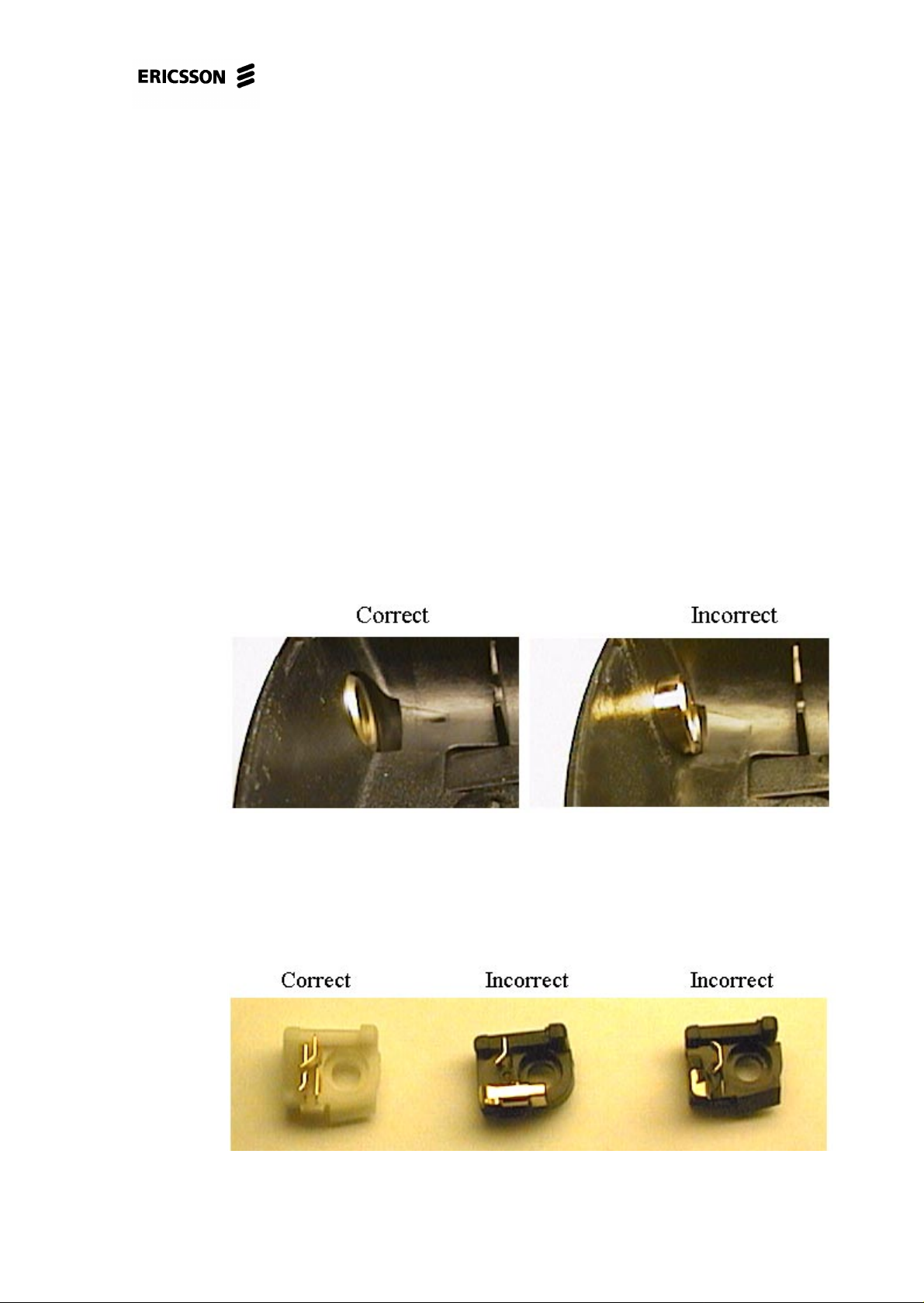
Open the phone and check for liquid damages.
Make sure the back cover isn’t broken or of the wrong model since there are two to
choose from. Fig. 2.1 shows what model of back cover is to be used.
Fig. 2.1
Replace the antenna connector. Note that there are several models to choose from
and you must use the correct model. Fig. 2.2 shows what antenna connector model
is to be used.
Fig. 2.2
4/00021-2/FEA 209 544/12.B 6 (60)
Page 7

T18s, T18sc Standard Electrical Repairs
Try again to get SERV at –102dBm.
• If the phone gets SERV at –102dBm there’s probably nothing wrong with the
phone. Run the phone through the final test (Go/No go-test).
Open the phone.
Give the board power and start it up by pressing the On/Off key.
Measure the VVCO voltage at pin 5 of N470 (fig. 2.3, ~3.8V).
• If the voltage is too low, replace N470 and C472 (both of class A and in fig. 2.3).
* If the voltage still is too low, send the phone to Advanced electrical
repairs.
Measure the resistances of C541-C546 (>200 kohms, fig. 2.3).
• If the resistance of any of the capacitors is too low, replace the corresponding
capacitor.
Check the solderings of Z530, C531 and L530 (fig. 2.3).
If the fault remains, send the phone to advanced electrical repairs.
4/00021-2/FEA 209 544/12.B 7 (60)
Page 8
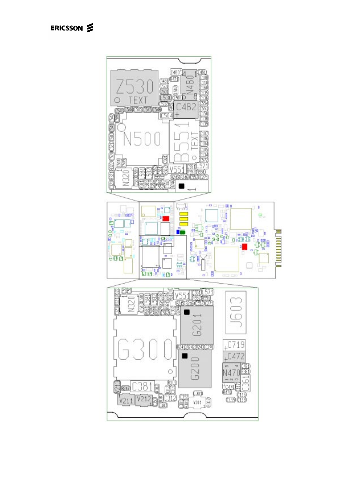
T18s, T18sc Standard Electrical Repairs
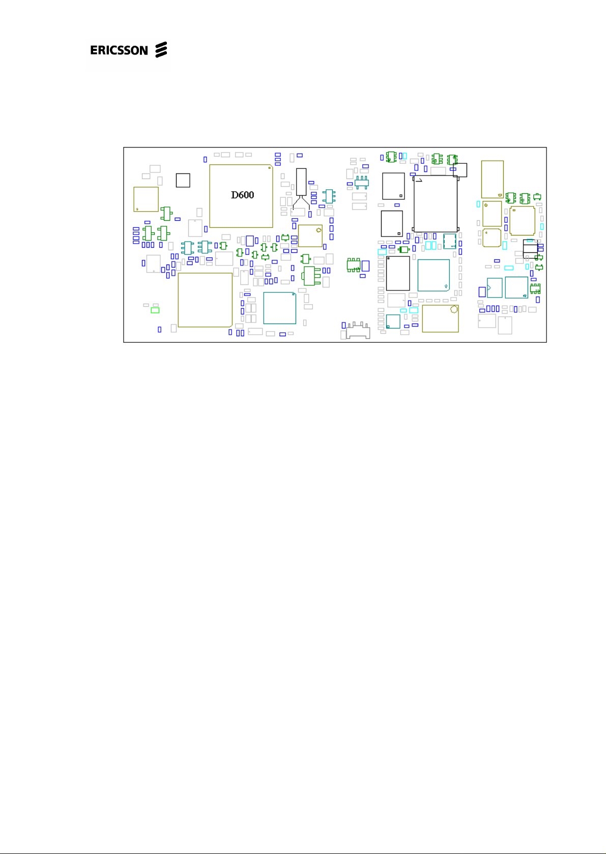
Fig. 2.3
4/00021-2/FEA 209 544/12.B 8 (60)
Page 9

T18s, T18sc Standard Electrical Repairs
2.3 Connect a call at powerlevel 5 towards the
instrument with an input signal of –
68.5dBm.
If you’re not able to connect a call, open the phone and check for liquid damages.
Make sure the back cover isn’t broken and that it is of the correct model as there are
two to choose from (fig. 2.1).
Replace the antenna connector (if it hasn’t been replaced before) and try again. Note
that there are several models to choose from and it’s important to mount the correct
one (fig.2.2).
If the phone still doesn’t work then the fault is most likely Tx-related or there’s a
feed voltage fault.
4/00021-2/FEA 209 544/12.B 9 (60)
Page 10
T18s, T18sc Standard Electrical Repairs
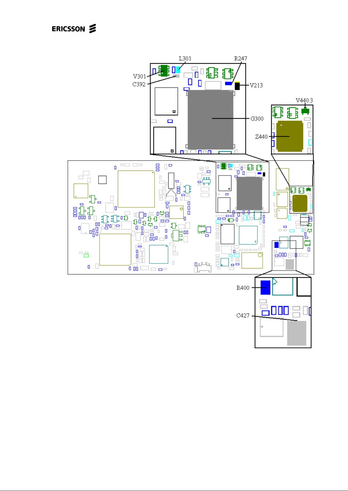
Fig. 2.4
Give the board power and start it up (in the fixture).
Measure the VRAD voltage at C482 (~3.8V, fig. 2.3).
• If the voltage is incorrect, replace N480 (class A, fig. 2.3).
Check the solderings of G300 and Z440 (fig. 2.4).
Make sure L301, C392 and V301 (fig. 2.4) aren’t burnt.
If the fault remains, send the phone to Advanced electrical repairs.
4/00021-2/FEA 209 544/12.B 10 (60)
Page 11

T18s, T18sc Standard Electrical Repairs
2.4 No SERV at the GSM 900 or the GSM 1800
band.
2.4.1 No SERV at the GSM 900 band.
Measure the voltage drop of the V213 diode (~0.6V, fig. 2.3, class A).
Measure the resistance of R247 (~33 kohms, class A, fig. 2.3).
Measure the voltage at pin 3 of G201 (fig. 2.3) when you’re starting the phone.
There should be a voltage peak of ~3.5V.
• If there is no voltage peak, replace V211 (class B), V212 (class B) and C271
(class A, all in fig. 2.3).
2.4.2 No SERV at the GSM 1800 band.
Measure the voltage at pin 3 of G200 when you’re starting the phone. There should
be a voltage peak of ~3.5V.
• If there is no voltage peak, replace V211 (class B) and C270 (class A, both in fig.
2.3).
If the fault remains, send the phone to Advanced electrical repairs.
4/00021-2/FEA 209 544/12.B 11 (60)
Page 12
3 Doesn’t start.
3.1 Find out if the phone starts when pressing
the On/Off key.
Insert a fully charged battery into the phone and press the On/Off key.
• If the phone doesn’t start, proceed to section 3.2.
• If the phone starts, check the charging function as described in the “Charging”
chapter (6.1.1).
3.2 Visual check.
Make an outer visual check.
• Make sure the battery connector isn’t broken and that the connector pins aren’t
dirty or oxidised.
• Make sure the system connector isn’t dirty or liquid damaged.
T18s, T18sc Standard Electrical Repairs
Open the phone and make a visual check of the circuit board.
• Check for any liquid damages and dirty or oxidised system and battery connector
pads, especially at the battery connector pads.
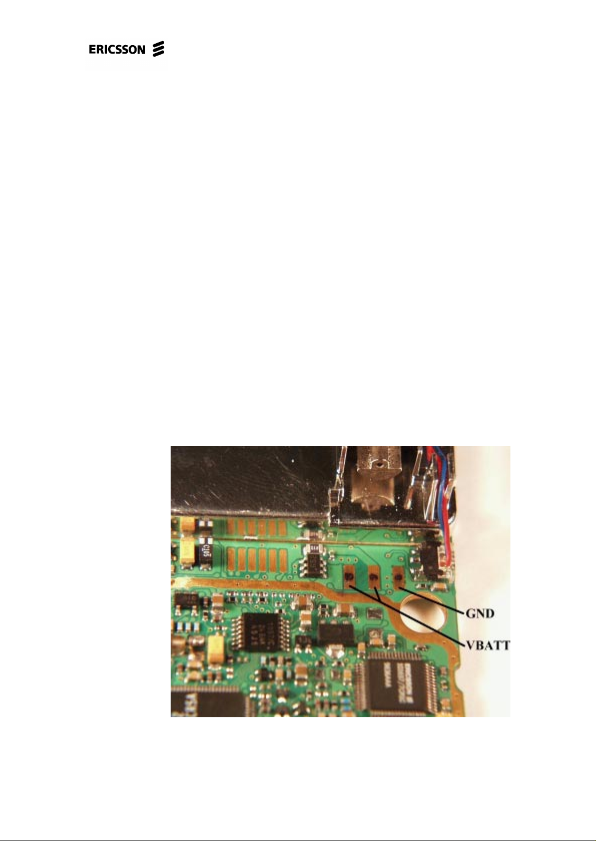
Fig. 3.1 shows typical dirt at the battery connector pads.
Fig. 3.1
4/00021-2/FEA 209 544/12.B 12 (60)
Page 13
T18s, T18sc Standard Electrical Repairs
Make sure the dome foil isn’t damaged, especially at the On/Off key.
Make sure there are no faulty solderings at D600 (fig. 3.2, class B).
Fig. 3.2
• If the fault is fixed, send the phone through the normal flow.
If the fault remains, continue at 3.3.
3.3 Current consumption with the On/Off key
pressed.
Insert a dummy battery into the phone.
• If the phone consumes current immediately, proceed to section 3.4.1.
Start the phone by pressing the On/Off key and check the current consumption.
If the phone doesn’t consume any current when the On/Off key is being pressed it’s
most likely the dome foil that’s faulty.
• Open the phone and remove the dome foil.
• Make sure there is no liquid damages at the circuit board, especially around the
On/Off key. Any dirt at the keypads is cleaned away using a brush and alcohol.
• Mount a new dome foil (note that the circuit board must be dry when mounting a
new dome foil).
• Give the board power and start it up (in the fixture or in the back cover with the
system connector mounted to make the board lie steady).
• If the phone doesn’t consume any current when the On/Off key is being pressed,
proceed to section 3.4.2.
4/00021-2/FEA 209 544/12.B 13 (60)
Page 14

T18s, T18sc Standard Electrical Repairs
If the phone consumes more than 200mA, remove the display and check again.
• The fault was due to the display if the current consumption went down.
• If the current consumption still is too high, proceed to section 3.4.3.
If the phone consumes between 1 and 200 mA, starts (asks for SIM, searches for a
net...) and works as long as the On/Off key is pressed, but shuts off at once when the
key is released, proceed to section 3.4.4.
If the phone doesn’t start, try programming it in the flash programmer.
• If the phone doesn’t start in the flash programmer, proceed to section 3.4.5.
• If you’re able to program the phone but it doesn’t start afterwards or if the phone
is troublesome in the flash programmer, proceed to section 3.4.6.
• If the phone starts after programming it in the flash programmer there’s probably
nothing wrong with the phone but to eliminate intermittent faults, check the circuit board for liquid damages and make sure there are no faulty solderings at
D600 (fig. 3.2).
3.4 Measuring a powered board.
3.4.1 Consumes current immediately (without the On/
Off key being pressed or DCIO kept high).
Open the phone and check for liquid damages.
Make sure the pads for the battery connector and system connector aren’t dirty, oxi-
dised or liquid damaged.
Remove the dome foil and clean the keypads using a brush and alcohol.
Place the circuit board in the fixture without starting it up.
Check the voltages VDIG, VCORE, VRAD, VVCO and VRPAD (fig. 3.3).
4/00021-2/FEA 209 544/12.B 14 (60)
Page 15

T18s, T18sc Standard Electrical Repairs
Fig. 3.3
4/00021-2/FEA 209 544/12.B 15 (60)
Page 16
T18s, T18sc Standard Electrical Repairs
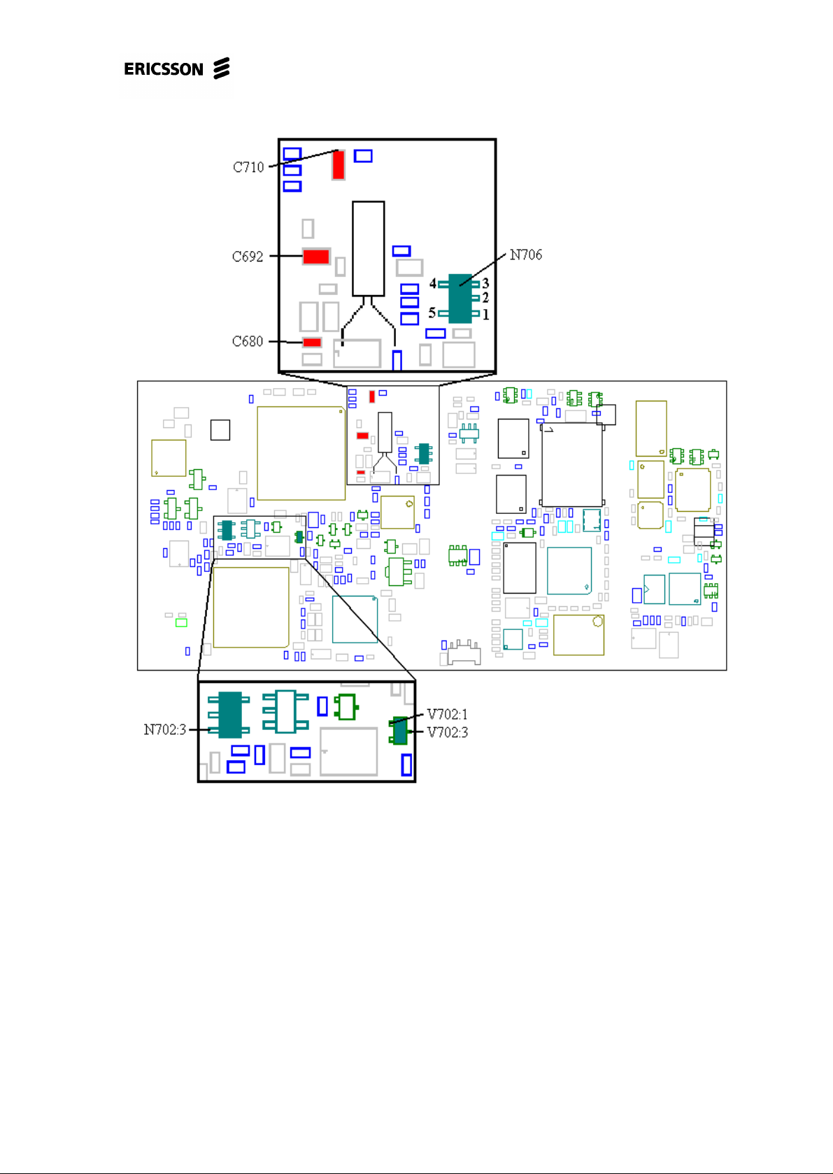
Fig. 3.4
• If there’s voltage at any of the regulators, replace the corresponding regulator
(VDIG – N702, VRAD – N480, VVCO – N470, VCORE – N700, all four of
class A).
• If there’s voltage at all of the regulators, measure the voltage at pin 1 of V702
(~0V, fig. 3.4).
* If the voltage is correct, send the phone to Advanced electrical repairs.
* If the voltage is incorrect there’s probably a short circuit at the On/Off key-
pads. It’s almost always crumbs from the dome foil that causes it. Clean it
away using alcohol and a brush.
If the fault remains, send the phone to Advanced electrical repairs.
4/00021-2/FEA 209 544/12.B 16 (60)
Page 17

T18s, T18sc Standard Electrical Repairs
3.4.2 Consumes no current when the On/Off key is
being pressed.
Open the phone and check for liquid damages.
Make sure the pads for the battery connector and system connector aren’t dirty, oxi-
dised or liquid damaged.
Give the board power and start it up.
Check the current consumption.
• If the phone still doesn’t consume any current, measure the resistance from the
marked side of the “No” key (On/Off, fig. 3.5) to pin 1 of V702 (fig. 3.4, ~2.2
kohms).
* If the resistance is correct, measure the resistance from pin 3 of V702 to pin
3 of N702 (fig. 3.4, ~0 ohms).
* If the resistance is correct, replace V702 (fig. 3.4, class A).
* If the resistance is incorrect there’s a foil damage and the phone is to be
discarded.
* If the resistance is incorrect there’s a foil damage and the phone is to be discarded.
Fig. 3.5
If the fault remains, send the phone to Advanced electrical repairs.
4/00021-2/FEA 209 544/12.B 17 (60)
Page 18

T18s, T18sc Standard Electrical Repairs
3.4.3 Consumes more than 200mA.
Open the phone and check for liquid damages.
Make sure the pads for the battery connector and system connector aren’t dirty, oxi-
dised or liquid damaged.
Put the board in the fixture, start it up and keep it running by keeping DCIO high.
Check the VDIG (~3.2V) and VCORE (~2.5V, both in fig. 3.3) voltages.
• If any of the voltages are too low, measure the resistance from it to ground
(VDIG>48 kohms, VCORE>40 kohms).
* If the resistance is correct, replace the corresponding regulator (VDIG –
N702, VCORE – N700, both of class A).
* If the resistance is incorrect, send the phone to Advanced electrical
repairs.
• If the VDIG and VCORE voltages are correct, check the VRAD (~3.8V), VVCO
(~3.8V), VRPAD (~3.2V, all in fig. 3.3) voltages.
* If any of the voltages are too low, measure the resistance from it to ground
(VRAD and VVCO>100 kohms, VRPAD>40 kohms).
*If the resistance is correct, replace the corresponding regulator (VRAD –
N480, VRPAD – N702 and VVCO – N470), all of class A).
* If the resistance is too low there’s a short circuit in one of the circuits fed
by that voltage. Send the phone to Advanced electrical repairs.
* If the voltages are correct, measure the resistance from VBATT to ground
(>500 kohms, fig. 3.1).
* If the resistance is incorrect, send the phone to Advanced electrical
repairs.
4/00021-2/FEA 209 544/12.B 18 (60)
Page 19

T18s, T18sc Standard Electrical Repairs
Fig. 3.6
3.4.4 The phone works as long as the On/Off key is
pressed.
Open the phone and check for liquid damages.
Make sure the pads for the battery connector and system connector aren’t dirty, oxi-
dised or liquid damaged.
Put the board in the fixture. Give the board power, start it up and keep it running by
keeping the On/Off key pressed.
Measure the voltage at C692 (~3V, fig. 3.4).
• If the voltage is incorrect, make sure the soldering at pin 119 of D600 isn’t
faulty.
4/00021-2/FEA 209 544/12.B 19 (60)
Page 20

T18s, T18sc Standard Electrical Repairs
* If it isn’t, replace D600 (class B, fig. 3.2).
• If the voltage is correct, measure the resistance of C692 (>200 kohms, fig. 3.4).
* If it’s incorrect, replace C692 (class A).
* If the resistance is correct, check the voltages at N706 (pin 1 – GND, pin2 –
VBATT, pin 3 - ~3V output voltage, fig. 3.4).
* If VBATT or GND is missing there’s a foil damage and the phone is to
be discarded.
* If the output voltage is incorrect, replace N706 (class A).
* If all the voltages are correct, measure the VRTC voltage at the positive
side of C720 (class A, fig. 3.6, ~3V).
* If the voltage is missing, replace V711 (class A, fig. 3.6).
* If the voltage is correct, measure the resistance from the positive side
of C720 (fig. 3.6) to the marked side of C692 (fig. 3.4, ~0 ohms).
* If the resistance is too high there’s a foil damage and the phone is
to be discarded.
If the fault remains, send the phone to Advanced electrical repairs.
3.4.5 Doesn’t start in the flash programmer.
Open the phone and check for liquid damages.
Make sure the pads for the battery connector and system connector aren’t dirty, oxi-
dised or liquid damaged.
Put the board in the fixture, start it up and keep it running by keeping DCIO high.
Check the VDIG (~3.2V) and VCORE (~2.5V) voltages (fig. 3.3).
• If any of the resistances are too low, measure the resistance from it to ground
(VDIG>48 kohms, VCORE>40 kohms).
* If the resistance is correct, replace the corresponding regulator (VDIG –
N702, VCORE – N700, both of class A).
• If the resistances are correct, check the power reset voltage at C710 (fig. 3.4,
>3V).
* If the voltage is incorrect, replace C710 (class A).
* If it is correct, make sure there are no faulty solderings at D600 (fig. 3.2).
* If the solderings are correct, measure the amplitude (>0.6V p-p) of the
MCLK signal (master clock, 13MHz)at C680 (Fig. 3.4) using an oscilloscope or a diode probe (if possible).
* If the amplitude is correct, replace D600 (class B, fig. 3.2).
* If the amplitude is too low, replace C680 (class A, fig. 3.4).
4/00021-2/FEA 209 544/12.B 20 (60)
Page 21

T18s, T18sc Standard Electrical Repairs
If the fault remains, send the phone to Advanced electrical repairs.
4/00021-2/FEA 209 544/12.B 21 (60)
Page 22

4 Audio.
T18s, T18sc Standard Electrical Repairs
4.1 Kind of fault.
Make a call from the phone that is to be tested (later called the phone) to a phone
that is working correctly (later called the reference phone).
Check the function of the microphone and the earphone.
Connect a handsfree unit to the system connector of the phone.
Check the function of the phone’s external connections by listening to the external
speaker/earphone when talking in the reference phone and by listening to the earphone of the reference phone when talking in the external mic of the phone.
• If there is a low or no sound in the earphone of the phone, proceed to section 4.2.
• If both the earphone and the handsfree speaker don’t work, send the phone to
Advanced electrical repairs.
• If the sensitivity of the microphone is low (low or no sound in the reference
phone), proceed to section 4.3.
• If both the microphone in the phone and the microphone of the handsfree don’t
work, send the phone to Advanced electrical repairs.
• If both the microphone and the earphone don’t work, proceed to section 4.4.
• If the microphone, the earphone and the handsfree don’t work, send the phone to
Advanced electrical repairs.
• If the microphone of the handsfree doesn’t work, proceed to section 4.5.
• If the speaker of the handsfree doesn’t work, proceed to section 4.6.
• If both the microphone and the speaker of the handsfree don’t work, proceed to
section 4.7.
• If the phone sounds strange (the sound is distorted, scrambled, full of static or
“chopped”), send the phone to Advanced electrical repairs.
• If the phone isn’t able to mute a car stereo through a car mounted handsfree (the
mute signal doesn’t work), proceed to section 4.8.
4.2 Earphone out of order.
Open the phone and check for liquid damages.
Most of the earphone faults are mechanical. Therefore you should start with replac-
ing the front (with the earphone) to one you know works and try again.
If the fault remains, make sure the earphone connector (J810, fig. 4.1) is intact and
correctly soldered.
4/00021-2/FEA 209 544/12.B 22 (60)
Page 23

T18s, T18sc Standard Electrical Repairs
Fig. 4.1
Check the solderings of N800 (fig. 4.2)
Measure the resistance from one of the J810 pins to the other (~14 kohms, fig. 4.1).
• If the resistance is too low, replace C842 (class A, fig. 4.1).
Measure the resistance from each of the J810 pins to ground (>1 Mohms).
• If any of the resistances are too high, replace C840 and C841 (class A, fig. 4.1)
If the fault remains, send the phone to Advanced electrical repairs.
4/00021-2/FEA 209 544/12.B 23 (60)
Page 24

T18s, T18sc Standard Electrical Repairs
4.3 Microphone out of order.
Open the phone and check for liquid damages.
Clean the system and microphone connector pads if needed.
Most of the microphone faults are mechanical.
Make sure C815 and C820 (both of class A, fig. 4.2) are mounted at the circuit
board. They easily fall of when removing the system connector.
Fig. 4.2
Make sure the sound channel gasket is free from dust and correctly mounted.
Replace the system connector and the microphone to a pair you know work. Assem-
ble the phone and check if the microphone works.
Measure the resistance of C850 and C851 (fig. 4.2, both of class A and >100
kohms).
Measure the resistance of R817, R814 (both of class A and ~1 kohms, fig. 4.2) and
R818 (19 kohms, class A, fig. 4.2).
4/00021-2/FEA 209 544/12.B 24 (60)
Page 25

T18s, T18sc Standard Electrical Repairs
Check the solderings at pins 13-17 of N800 (fig. 4.2).
If the fault really is electrical and the above mentioned components aren’t faulty,
replace C818 and C819 (class A, fig. 4.2).
Measure the resistance from one of the X830 pads to the other (~28 kohms, fig.4.2).
• If the resistance is incorrect, replace C815 (class A, fig. 4.2).
Measure the resistance from pad 1 of X830 to ground (fig. 4.2, ~27 kohms).
• If the resistance is incorrect, measure the resistances of R812 and R814 (~470
ohms, class A, fig. 4.2).
* If the resistance is correct, measure the resistance from pad 1 of X830 to pin
13 of N800 (<1 kohms, fig. 4.2).
* If the resistance is to high there’s a foil damage and the phone is to be
discarded.
Measure the resistance from pad 2 of X830 to ground (fig. 4.2, ~470 ohms).
• If the resistance is too low, replace C820 (class A, fig. 4.2).
• If the resistance is too high, replace R820 (~470 ohms, class A, fig. 4.2).
If the fault remains, send the phone to Advanced electrical repairs.
4.4 Both the earphone and the microphone out
of order.
Open the phone and check for liquid damages.
Make especially sure there’s no dirt or oxide between the components below the
dome foil (components in fig. 4.1) and at the system connector pads.
Clean the circuit board if needed using alcohol and a brush.
Assemble the phone and test it again as described in section 4.1 (call a reference
phone).
If the fault remains, open the phone. Give the board power and start it up without the
system cable connected by pressing the On/Off key.
Measure the VDIG voltage (~3.2V, fig. 4.3).
• If the voltage is incorrect, proceed to chapter 3, “Doesn’t start”-fault.
4/00021-2/FEA 209 544/12.B 25 (60)
Page 26

T18s, T18sc Standard Electrical Repairs
Fig. 4.3
Measure the voltage at both sides of R601 and at pin 70 of D600 (~3.1V, fig. 4.2,
you follow the PHFI signal).
Measure the voltage at both sides of R605 and at pin 67 of D600 (~3.1V, fig. 4.2,
you follow the EXTAUDI signal).
• If the voltage at R601 or R605 (both of class A) is too low only at one side (the
marked side), remove the resistor and measure the resistance from the marked
side to ground (fig. 4.2, >2 Mohms).
* If the resistance is correct, mount a new resistor where you removed the old
one.
* If the resistance is too low there’s a short circuit in either the circuit board
or in D600. Replace D600 (class B, fig. 4.2).
* If that doesn’t help there’s a foil damage and the phone is to be discarded,
• If the voltage is too low at both sides of R601 or R605, measure the resistances
of R635 and R636 (~22 kohms, class A, fig. 4.2).
* If the resistance of any of the resistors is incorrect, replace the corresponding resistor.
4/00021-2/FEA 209 544/12.B 26 (60)
Page 27

T18s, T18sc Standard Electrical Repairs
Check the VDIG voltage at the marked sides of R635 and R636 (~3.2V, fig. 4.1).
• If VDIG is missing at R635 and R636 but is at pin 5 of N702 there’s a foil dam-
age and the phone is to be discarded.
• If the voltage is correct, check the solderings at N800 and D600 (fig. 4.2).
Fig. 4.4
If the fault remains, send the phone to Advanced electrical repairs.
4.5 Handsfree microphone out of order.
The fault occurs when there’s an interrupt in the audiopath between the handsfree
microphone (connected through the system connector) and the N800. The audio
path is shown in fig. 4.5.
Fig. 4.5
4/00021-2/FEA 209 544/12.B 27 (60)
Page 28

T18s, T18sc Standard Electrical Repairs
Open the phone and check for liquid damages especially around pads 1, 2 and 4 of
the system connector pads (J602, fig. 4.4).
Measure the resistance from pad 2 of J602 (fig. 4.4) to ground (>30 kohms).
• If the resistance is too low (short circuit at ATMS),replace F604 and C669 (both
of class A, fig. 4.7).
Measure the resistance of C850 and C851 (both are >100 kohms, in fig. 4.2 and of
class 2).
Make sure R830, C835, R825, C810, R802, R805 C812 and R803 (class A, fig. 4.2)
are mounted at the circuit board.
Check the solderings of N800 (fig. 4.2).
Give the board power and start it up without the system connector connected by
pressing the On/off key.
Measure the voltage at pad 2 of J602 (ATMS, ~3.1V, fig. 4.4).
• If the voltage is incorrect, measure the VDIG voltage at the marked side of R830
(fig. 4.2, ~3.2V).
* If the VDIG voltage is incorrect, proceed to chapter 3, “Doesn’t start”-fault.
* If the voltage is correct, check the resistances of R830 (~470 ohms, class
A), R825 (~3.3 kohms, class A), C835 (>1 kohms, class A) and C810 (>5
kohms, class A, all four in fig. 4.2).
• If the voltage at pad 2 of J602 is correct, check the resistances of C810 (>5
kohms), C812 (>5 kohms), R802 (~10 kohms), R805 (~15 kohms) and R803 (~1
kohms, all of class A and in fig. 4.4).
If the fault remains, send the phone to Advanced electrical repairs.
4.6 Handsfree speaker out of order.
The fault occurs when there’s an interrupt in the audio path from the N800 to the
handsfree speaker (connected through the system connector). The audio path is
shown in fig. 4.6.
Fig. 4.6
4/00021-2/FEA 209 544/12.B 28 (60)
Page 29

T18s, T18sc Standard Electrical Repairs
Open the phone and check for liquid damages, especially around the system connector pads 1, 2 and 4 (J602, fig. 4.4).
Measure the resistance from pad 1 of the system connector pads (J602) to ground.
• If the resistance is less than 10 kohms, replace F601 and C668 (both of class A,
fig. 4.7).
Measure the resistances of C850 and C851 (both are >100 kohms, in fig. 4.2 and of
class A).
Make sure all the components in fig. 4.6 (R806, R804 and C813 in fig. 4.2 and F601
and C668in fig. 4.7, all of class A) are mounted at the circuit board.
Check the solderings of N800 (fig. 4.2).
Measure the resistances of R806 (~100 ohms), R804 (~100 kohms) and C813 (>100
kohms, all of class A and in fig. 4.2).
Measure the resistance from the marked side of C813 to system connector pad 1
(J602, ~0 ohms, fig. 4.2 and 4.4).
• If the resistance is incorrect there’s a foil damage and the phone is to be dis-
carded.
Fig. 4.7
If the fault remains, send the phone to Advanced electrical repiars.
4.7 Both the handsfree microphone and
speaker out of order.
Open the phone and check for liquid damages, especially around the marked area
above the system connector pads (fig. 4.4).
4/00021-2/FEA 209 544/12.B 29 (60)
Page 30

T18s, T18sc Standard Electrical Repairs
Clean the marked area using a brush and alcohol.
Measure the resistance from pad 3 of J602 to unmarked side of R635 (~0 ohms,
fig. 4.4 and 4.1).
Measure the resistance from pad 5 of J602 to unmarked side of R636 (~0 ohms,
fig. 4.4 and 4.1).
• If any of the resistances are incorrect there’s a foil damage and the phone is to be
discarded.
Measure the resistances of R601 and R605 (both are ~1 kohms, of class A and in
fig. 4.2).
• If all the resistances are correct, check the solderings of N800 and D600 (fig.
4.2).
If the fault remains, send the phone to Advanced electrical repairs.
4.8 Mute fault.
Connect a call and measure the voltage between pin 4 (AGND) and pin 6 (Mute) of
J602 (~3.2V when a call is in progress, Fig. 4.4).
• If the mute voltage is correct the fault probably lies in the handsfree unit.
• If there’s no mute voltage, open the phone and check for liquid damages, espe-
cially around the system connector pads.
Measure the resistance from pad 6 of J602 to ground (>100 kohms, fig. 4.4).
• If the resistance is too low, replace F605 (class A, fig. 4.7).
* If the resistance still is incorrect, replace D600 (class B, fig. 4.2).
Measure the resistance from pad 6 of J602 to pin 92 of D600 (~470 ohms).
• If the resistance is incorrect, replace R602 (class A, fig. 4.2).
* If the resistance still is incorrect there’s probably a foil damage and the
phone is to be discarded.
• If the resistance is correct but the fault remains, replace D600 (class B, fig. 4.2).
4/00021-2/FEA 209 544/12.B 30 (60)
Page 31

5 Display.
5.1 Kind of fault.
Insert a fully charged battery into the phone and start it up by pressing the On/Off
key.
• If it doesn’t start, proceed to chapter 3, “Doesn’t start”-fault.
• If the display is missing one or more of the segments, proceed to section 5.2.
• If there’s nothing displayed in the display, proceed to section 5.3.
• If the display is completely black (all the segments are “lit”), proceed to section
5.2 Segments are missing.
Open the phone and check for liquid damages.
Replace the display.
T18s, T18sc Standard Electrical Repairs
5.3.
5.3 There’s nothing displayed in the display.
Insert a dummy battery into the phone, start it up and check the current consumption.
• If the phone consumes more than 200mA, make sure the display isn’t mechani-
cally damaged.
* If it isn’t, replace the elastomer and try again.
* If that doesn’t help, replace the display and try again.
* If the current consumption still is too high, proceed to chapter 3,
“Doesn’t start”-fault.
• If the phone consumes less than 200mA, open the phone and check for liquid
damages.
Give the board power and start it up.
Measure the voltage at the display pads (H623, fig. 5.1).
Pad 1: VLCD ~5.8V
Pad 2: VDIG ~3.2V
2
Pad 3: I
CDAT ~3.2V
Pad 4: GND
Pad 5: I
2
CCLK ~3.2V
4/00021-2/FEA 209 544/12.B 31 (60)
Page 32

T18s, T18sc Standard Electrical Repairs
Fig. 5.1
2
If I
CDAT or I2CCLK voltage is missing, measure the resistance of R619 (~6.8
kohms), R620 (~6.8 kohms), R615 (~0 ohms) and R614 (~10 kohms, all of class A,
R619 and R620 in fig. 5.2 and R615 and R614 in fig. 5.1).
• If any of the resistances are incorrect, replace the corresponding resistor.
• If the resistances are correct, measure the resistance from I
2
CDAT to ground
(>10 kohms).
* If the resistance is too low, replace V750 (class A, fig. 5.1).
Check the solderings at pin 3 and 4 of D600 (fig. 5.2).
• If the solderings are correct, replace D600 (class B).
If VLCD is incorrect, measure the voltage at pin 1 of V611 (~3.8V, fig. 5.2).
• If there’s no voltage, replace R480 (class A, fig. 5.2).
* If that doesn’t help, send the phone to Advanced electrical repairs.
Measure the resistance from VLCD to ground (>100 kohms).
• If the resistance is too low, replace C633 (class A, fig. 5.2).
* If the fault remains, replace F620 (class A, fig. 5.1).
Measure the voltages at pins 95 (~3.0V, PWM1) and 96 (~180mV, PWM0) of D600.
4/00021-2/FEA 209 544/12.B 32 (60)
Page 33

T18s, T18sc Standard Electrical Repairs
• If the PWM0 and PWM1 signals are missing, check the resistances of C634 and
C636 (both of class A and in fig. 5.2) to see if there’s a short circuit in one or
both of them.
* If there is a short circuit, replace the corresponding capacitor.
* If there is no short circuit in any of the capacitors there’s probably D600
(class B, fig. 5.2) that is faulty. Replace it.
If VLCD voltage is more than 6V, replace V608 (class A, fig. 5.2).
If VLCD voltage is less than 2.5V, check if the V608 and V611 (class A, fig. 5.2)
diodes are faulty (by measuring the voltage drop with a multimeter).
• If the diodes aren’t faulty, replace C634 and C636 (class A, fig. 5.2).
If VLCD is ~4.9V, measure the voltage at pin 2 of V611.
• If it is ~3.7V, replace C634 (class A).
• If it is ~5.8V, replace C636 (class A).
* If VLCD still is incorrect, measure the resistance from VLCD to V608 pin
2 (~0 ohms).
* If the resistance is too high there’s a foil damage and the phone is to be
discarded.
If the fault remains, send the phone to Advanced electrical repairs.
4/00021-2/FEA 209 544/12.B 33 (60)
Page 34

T18s, T18sc Standard Electrical Repairs
Fig. 5.2
5.4 Black display.
Open the phone and check for liquid damages. Try mounting a display that you
know works.
• If that doesn’t help, replace R807, R808 and C824 (fig. 5.2, all of class A).
If the fault remains, send the phone to Advanced electrical repairs.
4/00021-2/FEA 209 544/12.B 34 (60)
Page 35

6 Charging fault
6.1 Type of charging fault.
Perform a visual check of the battery connector and the system connector. Replace
if necessary. Start the phone using the On/Off-key and a fully charged battery.
• If it doesn´t start at all, proceed to chapter 3, "Doesn´t start"-fault
• If the phone starts and shows charging at once, proceed to section 6.2.
• If the phone doesn´t show charging, turn it off and connect a battery charger to
the system connector.
* If it starts, shows charging and the red top indicator flashes, the phone is
okay.
* If it doesn´t start, proceed to section 6.3.
* If it starts, but doesn´t show charging, proceed to section 6.4.
* If the phone starts and shows charging but the top indicator doesn´t flash,
proceed to the chapter 9; “Illumination, buzzer and vibrator”-faults.
T18s, T18sc Standard Electrical Repairs
6.1.1 Verification of the charging function.
Cut a cable from a battery charger to make a charging test cable.
Connect the charging test cable to a power supply that shows the current consump-
tion. Make sure the positive side from the power supply connects to DCIO (the
lonely pin on the system connector, pin 12).
Set the power supply to 7.6V and the current limit to 700 mA.
Another method is to use a regular battery charger with an ammeter connected in
series.
Connect the charging test cable to the system connector of the phone and check the
current consumption. It should be approximately 20 mA when the battery isn´t connected (Notice! This is only accurate on T18, not on older types of phones). Then
the ”Trickle Charge” function in N450 (class C) is active, i.e. the charging that is
made on a completely empty battery until the voltage of the battery is high enough
(>4,4 V) to start the rapid charging .
Attach a normal battery (not a so-called dummy battery) to the phone. The voltage
of the battery should be high enough to start the phone, otherwise the verification
will take too much time.
4/00021-2/FEA 209 544/12.B 35 (60)
Page 36

T18s, T18sc Standard Electrical Repairs
• If the phone starts and shows charging and the current consumption on the
power supply varies between ~700mA (the other method gives ~500-800 mA
depending on the type of charger) and 0 mA with a few seconds interval, the
charging function is without fault.
NOTE! After every repair of the charging function, including the repairs who
doesn´t demands current calibration in the test program EFRA, you
have to verify the charging function according to the instructions
above.
6.2 Shows charging without a charger being
connected.
Open the phone and check for liquid damages.
Give the board power and start it using the On/Off-key.
Fig. 6.1.
4/00021-2/FEA 209 544/12.B 36 (60)
Page 37

T18s, T18sc Standard Electrical Repairs
Check the feed voltages VDIG (~3.2 V) on the marked side of C600 (class A) and
VRAD (~3.8 V) on the marked side of C482 (class A, Fig. 6.1).
• If any of the feed voltages are incorrect, proceed to chapter 3, “Doesn´t start”-
fault.
• If the voltages are correct, the fault probably is due to N450 or N800, but both
are class C components and must be calibrated after being replaced. The calibration can only be done at Advanced electrical repairs.
Fig. 6.2.
6.3 Doesn´t begin to charge.
Open the phone and check for liquid damages.
Make sure the pads of the system connector are not burned or oxidated.
There is often dirt on the system connector, clean it with isopropyl alcohol and a
brush.
Measure the resistance of F603 (see Fig. 6.2), it should be >200 kOhm.
• If it is too low, replace F603 and C667 (both are class A and in fig. 6.2).
Measure the resistance between GND (pin 10) and AGND (pin 4) (Fig. 6.1) at the
system connector (~0 Ohm).
* If it is incorrect, is there a foil damage and the board has to be discarded.
Measure the resistance between V450 pin 1 and X800 pin 3 (see Fig. 6.1), it should
be < 1 kOhm.
4/00021-2/FEA 209 544/12.B 37 (60)
Page 38

T18s, T18sc Standard Electrical Repairs
• If it is too high, it is either R453 or R648 (both class A and in fig. 6.1) that is
faulty. Measure their resistance and replace the resistor that is faulty.
Measure the resistance between J602 pin 1 (DCIO) and X800 pin 3 (VBATT).
• If it is lower then 10 kOhm is V450 (class A) faulty and has to be replaced.
If the fault still remains, send the phone to Advanced electrical repairs.
6.4 Starts, but doesn´t begin to charge, even
though it shows charging.
Open the phone and check for liquid damages, especially at the system connector. If
the gold plating are damaged, the board has to be discarded.
Measure the resistance of R453 (~0.1 Ohm, fig. 6.1).
* If it is incorrect, replace R453 (class A).
Measure the resistance of R648 (~0 Ohm, fig. 6.1).
* If it is incorrect, replace R648 (class A).
Measure the resistance between DCIO and V450:6 (~0 Ohm, Fig. 6.1).
* If it is incorrect, is there a foil damage and the board has to be discarded.
Measure the resistance between GND (pin 10) and AGND (pin 4, Fig. 6.1) at the
system connector (~0 Ohm).
* If it is incorrect, is there a foil damage and the board has to be discarded.
If the fault still remains, send the phone to Advanced electrical repairs.
4/00021-2/FEA 209 544/12.B 38 (60)
Page 39

7 SIM fault ("Insert card")
7.1 What is a SIM fault?
Insert a working SIM card and attach a fully charged battery.
• If the phone shows "Wrong card" or "Insert correct card" when started, the
phone is SIM locked to a specific operator and can´t be repaired at this repair
level.
• If the phone shows "Phone lock", it is locked by the customer with a personal
code. The phone will be unlocked in the reset program in the normal repair flow.
• If the phone shows "PIN:" or "Enter PIN”, the SIM card is locked with a per-
sonal code.
• ONLY IF IT SHOWS “INSERT CARD” IT IS A SIM FAULT.
T18s, T18sc Standard Electrical Repairs
SIMCONDATA
SIMCONCLK
NC
SIMCONRST
GND
SIMVCC
Fig. 7.1.
4/00021-2/FEA 209 544/12.B 39 (60)
Page 40

T18s, T18sc Standard Electrical Repairs
This measurement is best performed using an oscilloscope, and that is also a common instrument at the Repair Centers. Therefore is this measurement included in
this instruction, even though the oscilloscope isn´t a required instrument.
Multimeter measuring.
Give the board power and start it. Measure VVIC at D901:1 (3.2 V).
If VVIC is missing, replace C901, C910 and R920 (class A).
If VVIC exists, measure the voltage at D901:2 (3.2 V)
Correct:
1. Measure the resistance between D901:8 and J603:2 (~33 Ohm).
Incorrect: 1. Rhange R600 (class A).
2. Foil damage, the board has to be discarded.
2. Measure the resistance between D901:11 and J603:7 (~33 Ohm).
Incorrect: 1. Replace R628 (class A).
2. Foil damage, the board has to be discarded.
3. Measure the resistance between D901:9 and J603:3 (~0 Ohm).
Incorrect: 1. Replace R627 (class A).
2. Foil damage, the board has to be discarded.
4. Measure the resistance between D901:11 and D901:14 (~15 kOhm).
Incorrect: 1. Replace R626 (class A).
2. Foil damage, the board has to be discarded.
5. Measure the resistance of C909 (> 1 MOhm).
Incorrect: Replace C909 (class A).
6. Measure the resistance between D901 pin14 and ground (>1 MOhm).
Incorrect: Replace C908 (class A).
7. Measure the resistance between D901 pin 14 and J603 pad 1 (~0 ohm).
Incorrect: Foil damage, the board has to be discarded.
8. Replace D901 (class A).
9. First replace R998 and R999 (class A), then D600 (class B).
Incorrect:
Measure the resistance between D901:2 and D600:77 (~0 Ohm).
Correct: Replace D600 (class B).
Incorrect: Foil damage, the board has to be discarded.
4/00021-2/FEA 209 544/12.B 40 (60)
Page 41

T18s, T18sc Standard Electrical Repairs
If the fault still remains, send the phone to Advanced electrical repairs.
Oscilloscope measuring.
Measure the voltage VVIC (suitably on a multimeter) at D901 pin 1, it should be
3.2V . If it is missing, replace C901, C910 and R920 (class A).
Set the oscilloscope for DC-measuring 1V/square and time setting Roll.
SIMVCC:
Measure at the SIMVCC-pad (see Fig. 7.1) while starting the phone. The phone
sends 5 pulses with an amplitude of 5 V at start up (see Fig. 7.2).
• If SIMVCC is missing at J603 pad 1, do the same test again, as above, but at
D901 pin 4 (see Fig. 7.1). The signal (SIMPWR) should look the same but with
the amplitude 3.2 V.
* If the signal (SIMPWR) is missing, do the same test, but at D600 pin 72.
* If SIMPWR is missing here too, replace D600 (class B).
* If SIMPWR exists (at D600 pin 72), then there is a foil damage and the
board has to be discarded.
* If SIMPWR exists at D901 pin 4, measure SIMVCC at D901 pin 14.
* If it is missing, replace first C908, C909 then D901 (class A).
* If SIMVCC exists at D901 pin 14, there is a foil damage between D901
pin 14 and J603 pad 1.
4/00021-2/FEA 209 544/12.B 41 (60)
Page 42

T18s, T18sc Standard Electrical Repairs
SIMVCC (J603:1)
SIMPWR (D901:1)
SIMCONRST (J603:2)
SIMRST (D901:7)
SIMCONDAT (J603:7)
SIMDAT (D901:5)
Fig. 7.2.
SIMCONRST
Measure at the SIMCONRST- pad (see Fig. 7.1) while starting the phone. The
phone sends 5 pulses with the amplitude 5 V at start up (see Fig. 7.2).
• If SIMCONRST is missing, do the same test as above, but at D901 pin 7 (see
Fig. 7.1). The signal (SIMRST) should look the same, but with the amplitude
3.2 V.
4/00021-2/FEA 209 544/12.B 42 (60)
Page 43

T18s, T18sc Standard Electrical Repairs
* If the signal (SIMRST) is missing, do the same test, but at D600 pin 73.
* If SIMRST is missing here too, replace D600 (class B).
* If SIMRST exists (at D600 pin 73), then there is a foil damage, and the
board has to be discarded.
* If SIMRST exists at D901 pin 7, measure SIMCONRST at D901 pin 8.
* If SIMCONRST is missing (at D901 pin 8), replace D901.
* If SIMCONRST exists at D901 pin 8, replace R600 (33 ohm) and meas-
ure again at J603 pad 2.
* If the signal is still missing, there is a foil damage between D901 pin
8 and J603 pad 2.
SIMCONCLK
Measure at the SIMCONCLK- pad (see Fig. 7.1) while starting the phone. The
phone sends 5 pulses with the amplitude 5 V at start up, these pulses are modulated
with a clock signal (see Fig. 7.2).
• If SIMCONCLK is missing, do the same test as above, but at D901 pin 6 (see
Fig. 7.1). The signal (SIMCLK) should look the same, but with the amplitude
3.2 V.
* If the signal (SIMCLK) is missing, do the same test, but at D600 pin 75.
* If SIMCLK is missing here too, replace D600 (class B).
* If SIMCLK exists (at D600 pin 75), replace R998 (class A) and measure
again at D901.
* If SIMCLK is still missing, then there is a foil damage, and the board
has to be discarded.
* If SIMCLK exists at D901 pin 6, measure SIMCONCLK at D901 pin 9.
* If SIMCONCLK is missing (at D901 pin 9), replace D901 (class A).
* If SIMCONCLK exists at D901 pin 9, replace R627 (0 ohm, class A)
and measure again at J603 pad 3.
* If the signal is still missing, there is a foil damage between D901 pin
9 and J603 pad 3.
4/00021-2/FEA 209 544/12.B 43 (60)
Page 44

T18s, T18sc Standard Electrical Repairs
SIMVCC
SIMCONCLK
(J603:3)
SIMCONCLK is
modulated by a
clock frequency
Fig. 7.3.
SIMCLK (D901:6)
SIMCONDATA
Measure at the SIMCONDAT- pad (see Fig. 7.1) while starting the phone. The
phone sends 5 pulses with the amplitude 5 V at start up (see Fig. 7.2).
4/00021-2/FEA 209 544/12.B 44 (60)
Page 45

T18s, T18sc Standard Electrical Repairs
• If SIMCONDAT is missing, do the same test as above, but at D901 pin 5 (see
Fig. 7.1). The signal (SIMDAT) should look the same, but with the amplitude
3.2 V.
* If the signal (SIMDAT) is missing, do the same test, but at D600 pin 74.
* If SIMDAT is missing here too, replace R999 (15 kOhm) first then D600
(class B).
* If SIMDAT exists (at D600 pin 74), then there is a foil damage, and the
board has to be discarded.
* If SIMDAT exists at D901 pin 5, measure SIMCONDAT at D901 pin 11.
* If SIMCONDAT is missing (at D901 pin 11), replace R626 (15 kOhm)
first then D901 (all class A).
* If SIMCONDAT exists at D901 pin 11, replace R628 (33 ohm, class A)
and measure again at J603 pad 7.
* If the signal is still missing, there is a foil damage between D901 pin
11 and J603 pad 7.
If the fault still remains, send the phone to Advanced electrical repairs.
4/00021-2/FEA 209 544/12.B 45 (60)
Page 46

8 Keyboard
8.1 Type of keyboard fault.
Insert a SIM card and attach a fully charged battery. Start the phone using the On/
Off-key.
• If the phone doesn´t start at all, proceed to chapter 3, “Doesn´t start”-fault.
• If the phone starts but no keys are working, proceed to section 8.2.
Press all keys (including the volume keys) and verify which one that doesn´t work.
The easiest way to do the verification is as follow:
1. Go to Menu/Settings/Key sound and choose “Click”.
2. Press the keys “1,2,3….*,0,#”. You should hear a click sound and see the corresponding figure in the display when pressing each key. Then press “Yes”, “No”,
“clr”, “<“ and “>”. When pressing ”Yes” the phone tries to connect a call, press
”No” and the phone should stop connecting a call. Press ”<” or ”>” and you
scroll the menus and ”Clr” clears the display from the figures that came up.
3. Press the volume keys, you should hear a click sound each time.
T18s, T18sc Standard Electrical Repairs
• If only the volume keys are faulty, proceed to section 8.3.
• If one or more of the keys on the keyboard are faulty, proceed to section 8.4.
• Close the flip, there should be a click sound. If not, proceed to section 8.5.
8.2 All keys are faulty.
Open the phone and check for liquid damages.
Measure the resistance of S15 (Fig. 8.1), it should be >1 MOhm. If there is a short
circuit, replace S15 (class A).
Remove the dome foil. Clean the pads and attach a new dome foil. Assemble the
phone and check if the keys are working according to section 8.1.
8.3 The volume keys are faulty.
Replace the faulty volume key (J820, J821, class A, fig. 8.1).
4/00021-2/FEA 209 544/12.B 46 (60)
Page 47

T18s, T18sc Standard Electrical Repairs
Fig. 8.1
8.4 One or more keys are faulty.
Open the phone and check for liquid damages. Remove the dome foil and clean the
pads.
Give the board power and start it. Check if there is a voltage on the marked sides of
the faulty pads (~4.8 V on the No/On-Off, ~3.2V on the other)(Fig. 8.2).
Attach a new dome foil and assemble the phone. Perform a new verification according to section 8.1.
Fig. 8.2.
4/00021-2/FEA 209 544/12.B 47 (60)
Page 48

T18s, T18sc Standard Electrical Repairs
Check the soldering at D600:1,120,122-128 (Fig. 8.3).
Fig. 8.3.
If the voltage is incorrect for a complete row (e.g. 1,2,3), measure the resistance
from the marked side (Fig. 8.2) of the pads of that row to D600 (In this case
D600:125). The resistance should be ~0 Ohm.
CORRECT: Replace D600 (class B).
INCORRECT: There is a foil damage and the board has to be discarded.
If one column or a part of it are faulty,check the soldering at D600:1 and D600:120-
128.
• If all soldering are correct, replace D600 (class B).
8.5 The active flip function doesn´t work.
Open the phone and check for liquid damages.
Measure the voltage on the marked side of S15 (3.2 V, Fig. 8.1).
Check if the keys [CLR] and [6] are working.
• If any of them doesn´t, return to section 8.4.
• If the keys [CLR] and [6] are working, replace S15 (class A).
* If the fault still remains, send the phone to Advanced electrical repairs.
4/00021-2/FEA 209 544/12.B 48 (60)
Page 49

T18s, T18sc Standard Electrical Repairs
9 Illumination, buzzer and vibrator.
9.1 Kind of fault.
Insert a dummy battery into the phone, start it up by pressing the On/Off key and
wait for the phone to get serv (towards the test instrument or the network).
• If the phone doesn’t beep directly at start, go to “Menu/Ring Vol” and try raising
the volume (not from full to “step” as that doesn’t generate any sound). If the
buzzer sounds faint or not at all, proceed to section 9.2.
• If the background illumination for the display doesn’t light up at start, proceed to
section 9.3.
• If the background illumination for the keyboard doesn’t light up at start, proceed
to section 9.4.
• If both the keyboard and the display illumination doesn’t work, proceed to section 9.5.
• If the top indicator doesn’t flash green when the phone has got serv, proceed to
section 9.6.
When the phone has got serv and the top indicator flashes green, lower the battery
voltage to 4.2V. The top indicator should then start to flash red, the battery indicator
in the display should be empty and start to flash and the phone should warn with a
beep.
• The phone needs a battery calibration if none of the above mentioned things happens.
• If the phone does everything but the top indicator doesn’t flash red, proceed to
section 9.7.
• If the phone doesn’t vibrate when called to, proceed to section 9.8.
9.2 Buzzer faint or dead.
Open the phone and check for liquid damages.
4/00021-2/FEA 209 544/12.B 49 (60)
Page 50

T18s, T18sc Standard Electrical Repairs
Fig. 9.1
Make sure the buzzer (H600, class A, fig. 9.1) isn’t incorrectly soldered at pins 1
and 2.
• If the solderings are correct, replace H600. Try the buzzer (by starting the board
in the fixture).
Give the board power and start it up.
Measure the voltage at pin 3 of V706 and pin 2 of V707 (~4.8V, fig. 9.1).
• If the voltage is correct, replace V706 and V707 (class A).
• If it’s incorrect, replace R606 (class A, fig. 9.1).
* If that doesn’t help there’s a foil damage and the phone is to be discarded.
Check the soldering at pin 91 of D600 (fig. 9.1, 9.2).
4/00021-2/FEA 209 544/12.B 50 (60)
Page 51

T18s, T18sc Standard Electrical Repairs
Measure the resistance from pin 91 of D600 to the marked side of R651 (~0 ohms,
fig. 9.1).
• If it’s correct, measure the resistance of R651 (1 kohms, fig. 9.1).
* If it’s incorrect, replace R651 (class A).
* If the resistance is correct, replace D600 (class B).
• If the resistance is incorrect there’s a foil damage and the phone is to be discarded.
9.3 Display illumination missing or faintly
glowing.
Open the phone and check for liquid damages.
Make sure all the LEDs (H651-H654, class A, fig. 9.1) are mounted and correctly
soldered.
Fig. 9.2
Give the board power and start it up.
If one or a few of the LEDs aren’t lit, measure the voltage of the LED from one side
to another.
• If the voltage is ~1.7V then the LED is faulty and is to be replaced.
4/00021-2/FEA 209 544/12.B 51 (60)
Page 52

T18s, T18sc Standard Electrical Repairs
• If the voltage is 0 V there’s a foil damage and the phone has to be discarded.
If none of the LEDs are lit, measure the voltage at the marked side of them (~4.8 V,
Fig. 9.1).
• If the voltage is correct, replace V613 and R609 (class A, fig. 9.2).
• If it’s incorrect there’s a foil damage and the phone is to be discarded.
NOTE! Since the LEDs only are lit for ~10s you need to press a key before
measuring.
9.4 Keyboard illumination missing or faintly
glowing.
Open the phone and check for liquid damages.
Make sure all the LEDs (H655-H660, fig. 9.1) are mounted, correctly soldered and
mechanically intact.
Give the board power and start it up.
If one or a few of the LEDs aren’t lit, measure the voltage of the LED from one side
to another.
• If the voltage is ~1.7V then the LED is faulty and is to be replaced.
• If the voltage is 0V then there’s a foil damage and the phone has to be discarded.
If none of the LEDs are lit, measure the voltage at the marked side of them (~4.8V,
Fig 9.1).
• If the voltage is correct, replace V614 and R610 (class A, fig. 9.2).
• If it’s incorrect there’s a foil damage and the phone is to be discarded.
NOTE! Since the LEDs only are lit for ~10s you need to press a key before
measuring.
9.5 Both the keyboard and the display illumina-
tion doesn’t work.
Open the phone and check for liquid damages.
Give the board power and start it up.
Measure the voltage at the marked side of one of the LEDs (~4.8 V, Fig. 9.1).
• If the voltage is correct, measure the voltage at the marked side of R607 (fig. 6.2,
~0.5V).
* If it’s correct, replace R607 and R608 (class A, fig. 9.2).
* If the voltage is incorrect, check the soldering at pin 69 of D600.
4/00021-2/FEA 209 544/12.B 52 (60)
Page 53

T18s, T18sc Standard Electrical Repairs
* If the soldering is correct, replace D600 (class B, fig. 9.2).
• If the voltage is incorrect there’s a foil damage and the phone is to be discarded.
NOTE! Since the LEDs only are lit for ~10s you need to press a key before
measuring.
9.6 Green top indicator doesn’t work.
Open the phone and check for liquid damages.
Fig. 9.3
Make sure the double LED (H650, fig. 9.3) is correctly soldered.
Give the board power and start it up.
Measure the voltage at pin 4 of H650 (~3.2V).
• If the voltage is correct, replace H650 (class A).
* If that doesn’t help, replace R646 (class A, fig. 9.3).
If the fault remains, check the soldering at pin 94 of D600.
• If the soldering is correct, measure the resistance from pin 94 of D600 to pin 3 of
H650 (~330 ohms).
* If it’s correct, replace D600 (class B, fig. 9.2).
* If the resistance is incorrect there’s a foil damage and the phone is to be dis-
carded.
4/00021-2/FEA 209 544/12.B 53 (60)
Page 54

T18s, T18sc Standard Electrical Repairs
• If the voltage at H650 is incorrect, send the phone to Advanced electrical
repairs.
9.7 Red top indicator doesn’t work.
Open the phone and check for liquid damages.
Make sure the double LED (H650, fig. 9.3) is correctly soldered.
Give the board power and start it up.
Measure the voltage at pin 4 of H650 (~3.2V).
• If the voltage is correct, replace H650 (class A).
* If that doesn’t help, replace R647 (class A, fig. 9.3).
If the fault remains, check the soldering at pin 93 of D600.
• If the soldering is correct, measure the resistance from pin 93 of D600 to pin 3 of
H650 (~330 ohms).
* If it’s correct, replace D600 (class B, fig. 9.2).
* If the resistance is incorrect there’s a foil damage and the phone is to be dis-
carded.
• If the voltage at H650 is incorrect, send the phone to Advanced electrical
repairs.
9.8 The vibrator doesn’t work.
Open the phone and check for liquid damages.
4/00021-2/FEA 209 544/12.B 54 (60)
Page 55

T18s, T18sc Standard Electrical Repairs
Fig. 9.4
Make sure: that there isn’t a cable breakage.
that the connector is properly attached to X680 (fig. 9.5, class A).
that X680 isn’t damaged or incorrectly soldered.
4/00021-2/FEA 209 544/12.B 55 (60)
Page 56

T18s, T18sc Standard Electrical Repairs
Fig. 9.5
Measure the voltage at pin 3 of V620 (~4.8V, fig. 9.5).
• If the voltage is missing, replace R685 (class A, fig. 9.5).
Also measure the voltage at pin 2 of V622 (~3.2 V, fig. 9.5).
• If the voltage is missing there’s a foil damage.
If both the voltages are correct, short circuit pin 2 and 3 of V620. That should start
the vibrator.
• If the vibrator doesn’t start, check the solderings of X680 (fig. 9.5) and try with a
vibrator that you know work.
• If the vibrator starts (when short circuiting V620), try to ground pin 1 of V622.
* If the vibrator starts, measure the resistance from pin 1 of V622 to D600 pin
45.
* If the resistance is more than 10 ohms, measure the resistance of R611
(0 ohms, class A, fig. 9.5).
* If the resistance is correct there’sa foil damage and the phone is to be
discarded.
4/00021-2/FEA 209 544/12.B 56 (60)
Page 57

T18s, T18sc Standard Electrical Repairs
• If the vibrator doesn’t start when grounding pin 1 of V622, measure the voltage
at pin 1 of V620 at the same time as you ground pin 1 of V622.
* If it’s less than 4.5V, measure the resistance of R681 (~1.5 kohms, fig. 9.5).
* If the resistance is correct, replace V620 (class A).
* If it’s more than 4.5V, replace V622, V621, R680 and R681 (all of class A
and in fig. 9.5).
If the fault remains, send the phone to Advanced electrical repairs.
4/00021-2/FEA 209 544/12.B 57 (60)
Page 58

10 RTC
T18s, T18sc Standard Electrical Repairs
10.1 Finding the fault.
Start the phone with a SIM-card and a fully charged battery attached. Set the clock
at the correct time. Remove the battery and attach it again after one minute.
* If the clock in the phone shows 00:00, proceed to section 10.2.
Compare to a clock with the correct time.
* If the clock in the phone is speeding or halted, proceed to section 10.3.
10.2 The clock shows 00:00 after removing and
reattaching the battery.
Open the phone and make sure the backup capacitor C720 (class A, Fig. 10.1) is
correctly soldered.
Fig. 10.1.
4/00021-2/FEA 209 544/12.B 58 (60)
Page 59

T18s, T18sc Standard Electrical Repairs
• If it is, replace it.
Assemble the phone, start it and set the clock at the correct time. Wait a few minutes
to allow the backup capacitor to begin charging. Remove the battery and attach it
again after one minute. Make sure the fault is fixed. (The backup capacitor needs to
be charged for a few hours before it is fully charged.)
Compare to clock with the correct time.
• If the clock in the phone is speeding or halted, proceed to section 10.3.
10.3 The clock is speeding or halted.
Fig. 10.2.
Open the phone and check the soldering at B600.
CORRECT: 1. Replace B600 (class A).
2. Replace C690 (class A) and C691 (class A).
Assemble the phone and compare to a clock with the correct time.
If the fault still remains, send the phone to Advanced Repair.
4/00021-2/FEA 209 544/12.B 59 (60)
Page 60

11 Component list
Component list in document 131 22- 2/FEA 209 544/12
T18s, T18sc Standard Electrical Repairs
4/00021-2/FEA 209 544/12.B 60 (60)
 Loading...