

Page 1

SVP 2000 Video Processor
Software Version 3.0 (and later)
REFERENCE GUIDE
EN/LZT 790 0046/1 R1A
Page 2

SVP 2000 Video Processor
ENGLISH (UK) - READ THIS FIRST!
If you do not understand the contents of this manual. DO NOT OPERATE
THIS EQUIPMENT. Also, translation into any EC official language of this
manual can be made available, at your cost.
ITALIANO - LEGGERE QUESTO AVVISO PER PRIMO!
Se non si capisce il contenuto del presente manuale. NON UTILIZZARE
L’APPARECCHIATURA.. È anche disponibile la versione italiana di questo
manuale, ma il costo è a carico dell’utente.
SVENSKA - LÄS DETTA FÖRST!
Om Ni inte förstår informationen i denna handbok. ARBETA DÅ INTE MED
DENNA UTRUSTNING. En översättning till detta språk av denna handbok
kan också anskaffas, på Er bekostnad.
PORTUGUÊS - LEIA O TEXTO ABAIXO ANTES DE MAIS NADA!
Se não compreende o texto deste manual. NÃO UTILIZE O
EQUIPAMENTO. O utilizador poderá também obter uma tradução do
manual para o português à própria custa.
FRANÇAIS - AVANT TOUT, LISEZ CE QUI SUIT!
Si vous ne comprenez pas les instructions contenues dans ce manuel. NE
FAITES PAS FONCTIONNER CET APPAREIL. En outre, nous pouvons
vous proposer, à vos frais, une version française de ce manuel.
DEUTSCH - LESEN SIE ZUERST DIESEN HINWEIS!
Sollte Ihnen der Inhalf dieses Handbuches nicht klar verständlich sein,
dann. BEDIENEN SIE DIESE GERÄTE NICHT! Eine Übersetzung des
Handbuches in diese Sprache ist gegen Berechnung lieferbar.
ESPAÑOL - LEA ESTE AVISO PRIMERO!
Si no entiende el contenido de este manual. NO OPERE ESTE EQUIPO.
Podemos asimismo suministrarle una traducción de este manual al (idioma)
previo pago de una cantidad adicional que deberá abonar usted mismo.
NEDERLANDS - LEES DIT EERST!
Als u de inhoud van deze handleiding niet begrijpt. STEL DEZE
APPARATUUR DAN NIET IN WERKING. U kunt tevens, op eigen kosten,
Jos et ymmärrä käsikirjan sisältöä. ÄLÄ KÄYTÄ LAITETTA. Käsikirja
Udstyret må ikke betjenes. MEDMINDRE DE TIL FULDE FORSTÅR
INDHOLDET AF DENNE HÅNDBOG. Vi kan også for Deres regning levere
Αν δεν καταλάβετε το περιεχόμενο αυτού του βοηθήματος/εγχειριδίου. ΜΗΝ
ΛΕΙΤΟΥΡΓΗΣΕΤΕ ΑΥΤΟΝ ΤΟΝ ΕΞΟΠΛΙΣΜΟ. Επίσης, αυτό το εγχειρίδιο
είναι διαθέσιμο σε μετάφραση σε αυτή τη γλώσσα και μπορείτε να το
een vertaling van deze handleiding krijgen.
SUOMI - LUE ENNEN KÄYTTÖÄ!
voidaan myös suomentaa asiakkaan kustannuksella.
DANSK - LÆS DETTE FØRST!
en dansk oversættelse af denne håndbog.
ΕΛΛΗΝΙΚΑ - ΔΙΑΒΑΣΤΕ ΠΡΩΤΑ ΑΥΤΟ!
αγοράσετε.
yright
Cop
© Copyright Ericsson AB 2014. All rights reserved.
Disclaimer
No part of this document may be reproduced in any form without the written permission of the
copyright owner.
The contents of this document are subject to revision without notice due to continued progress in
methodology, design and manufacturing. Ericsson shall have no liability for any error or damage of
any kind resulting from the use of this document.
ii
EN/LZT 790 0046/1 R1A
Page 3

Contents
Contents
Chapter 1: Introduction
This chapter identifies the equipment covered by this manual; describes the purpose
of the equipment in a typical system; provides a summary of its main features;
identifies the controls, indicators and connectors in a guided tour of the front and
rear panels.
Chapter 2: Installing the Equipment
This chapter provides product specific installation information including rack
mounting, ventilation and pin-out details of the external connectors.
Chapter 3: Getting Started
This chapter provides a guide to powering up the unit, and setting up and using the
unit.
Chapter 4: SVP 2000 Encoder Web-based GUI Control
This chapter describes the configuration of the Encoder using the Web based GUI. It
includes descriptions of the GUI functions etc
Chapter 5: SVP 2000 Decoder Web-based GUI Control
This chapter describes the configuration of the Decoder using the Web based GUI.
It includes descriptions of the GUI functions etc
Chapter 6: Hardware Options, Software Licensing and Upgrades
This chapter provides details of options enabled via software licenses. It also gives
information regarding the Firmware Upgrade process.
Chapter 7: Preventive Maintenance and Troubleshooting
This chapter details routine maintenance tasks to be performed; provides general
servicing advice, and information regarding warranty and maintenance and any
appropriate Operator action to be taken; provides general fault-finding information
for other types of problem which may be encountered; and provides relevant
disposal information.
Annex A: Glossary
Annex B: Technical Specification
Annex C: Alarms List
EN/LZT 7
90 0046/1 R1A
iii
Page 4

Preliminary Pages
Introduction
This Reference Guide provides instructions and information for the installation,
operation of the SVP 2000 Video Processor.
This Reference Guide should be kept in a safe place for reference for the life of the
equipment. It is not intended that this Reference Guide will be amended by the issue
of individual pages. Any revision will be by a complete reissue. Further copies of this
Reference Guide can be ordered from the address listed in Customer Services. If
passing the equipment to a third party, also pass the relevant documentation.
Revision History
Issues of this Reference Guide are listed below:
Issue Date Software Version Comments
A July 2014 3.0 Initial Release
Associated Documents
The following manuals/guides are also associated with this equipment:
Ericsson Document Identity Title
3/1424 EN/LZT 790 0051 Quick Guide
Useful Links:
Product Guide downloads are available for all Product Families:
http://www.ericsson.com/ourportfolio/products/television-and-video
iv
EN/LZT 790 0046/1 R1A
Page 5

Preliminary Pages
v
Trademarks
All best endeavors have been made to acknowledge registered trademarks and
trademarks used throughout this Reference Guide. Any notified omissions will be
rectified in the next issue of this Reference Guide. Some trademarks may be
registered in some jurisdictions but not in others.
Registered trademarks and trademarks used are acknowledged below and marked
with their respective symbols. However, they are not marked within the text of this
Reference Guide.
Registered Trademarks
Dolby
®
Registered trademark of Dolby Laboratories Licensing
Corporation.
®
Ethernet
Ericsson
Firefox
Internet Explorer
Registered trademark of Xerox Corporation.
®
®
Registered trademark of Mozilla Foundation
Registered trademark of Ericsson AB.
®
, Microsoft® and Windows®
Registered trademarks of Microsoft Corporation.
Safari
®
Registered Trademark of Apple Corporation.
Trademarks
Apple™ Trademark of Apple Corporation.
Chrome™ Trademark of Google Inc.
Ethafoam™ Trademark of Dow Chemical Company.
Nagravison™
Trademark of Kudelski S.A.
Opera™ Trademark of Opera Software ASA.
Pozidriv™ Trademark of European Industrial Services.
Reflex™ Trademark of Ericsson Television.
Stratocell™ Trademark of the Sealed Air Corporation.
EN/LZT 7
90 0046/1 R1A
Page 6

Preliminary Pages
Warnings, Cautions and Notes
Heed Warnings
All warnings on the product and in the operating instructions should be adhered to.
The manufacturer can not be held responsible for injuries or damage where
warnings and cautions have been ignored or taken lightly.
Read Instructions
All the safety and operating instructions should be read before this product is
operated.
Follow Instructions
All operating and use instructions should be followed.
Retain Instructions
The safety and operating instructions should be retained for future reference.
Warning!
Warnings give information which, if strictly observed, will prevent personal injury or
death, or damage to property or the environment. They are highlighted for
emphasis, as in this example, and are placed immediately preceding the point at
which the reader requires them.
Caution!
Cautions give information which, if strictly followed, will prevent damage to
equipment or other goods. They are highlighted for emphasis, as in this example,
and are placed immediately preceding the point at which the reader requires them.
Note: Notes provide supplementary information. They are highlighted for
emphasis, as in this example, and are placed immediately after the relevant
text.
vi
EN/LZT 7
90 0046/1 R1A
Page 7

Preliminary Pages
Contact Information
Support Services
Our primary objective is to provide first class customer care that is tailored to your
specific business and operational requirements. All levels are supported by one or
more service performance reviews to ensure the perfect partnership between
Ericsson and your business.
Warranty
All Ericsson products and systems are designed and built to the highest standards
and are covered under a comprehensive 12 month warranty.
Levels of Continuing Ericsson Service Support
For standalone equipment, then Ericsson BASIC Essential support is the value for
money choice for you. BASIC provides you with year-by-year Service long after the
warranty has expired.
For systems support you can choose either Gold Business Critical support or
Silver Business Advantage. These packages are designed to save you costs and
protect your income through enlisting the help of Ericsson support specialists.
Call Ericsson Sales for more details.
Customer Services
Europe, Middle East
and Africa
Americas Tel: +888 671 1268
Asia Tel: +852 2590 3820
Australia and New
Zealand
Internet Address
Tel: +44 (0) 23 8048 4455
Fax: +44 (0) 23 8048 4467
Email: tvsupportemea@ericsson.com
Tel: +678 812 6255
Fax: +678 812 6262
Email: tvsupportamericas@ericsson.com
Fax: +852 2590 9550
Email: tvsupportapac@ericsson.com
Tel: +61 (0) 2 9111 4080
Fax: +61 (0) 2 9111 4949
Email: tvsupportanz@ericsson.com
www.ericsson.com
US and Canada
International
Hong Kong
Hong Kong
EN/LZT 7
90 0046/1 R1A
vii
Page 8

Preliminary Pages
Technical Training
Ericsson provides a wide range of training courses on the operation and
maintenance of our products and on their supporting technologies. Ericsson can
provide both regularly scheduled courses and training tailored to individual needs.
Courses can be run either at your premises or at one of our dedicated training
facilities.
International Tel: +44 (0) 23 8048 4229
Fax: +44 (0) 23 8048 4161
Email: tvglobaltraining@ericsson.com
Customer Services and Technical Training Postal Address
Ericsson
Unit 2
Strategic Park
Comines Way
Hedge End
Southampton
Hampshire
SO30 4DA
United Kingdom
Return of Equipment
If you need to return equipment for repair please contact your local Ericsson
Customer Services Department.
Please refer to the Customer Services Contact Information on Page vii
You will then be directed to return the faulty equipment to a repair centre with
the appropriate facilities for that equipment. A tracking number will be issued that
should be used if you need to enquire about the progress of the repair. The
equipment should be properly packed and the tracking number should be clearly
marked on the outside of the packaging
.
viii
Technical Publications
If you need to contact Ericsson Technical Publications regarding this publication,
e-mail: tvtechpubs@ericsson.com
EN/LZT 790 0046/1 R1A
Page 9

1 Introduction
Chapter 1
Contents
1.1 Scope of this Guide .............................................................................. 1-3
1.1.1 Who Should Use this Guide .................................................................1-3
1.1.2 What Equipment is Covered by this Reference Guide .........................1-3
1.1.2.1 Product Codes...................................................................................... 1-3
1.1.3 Equipment Label................................................................................... 1-4
1.1.3.1 Contents of the Label ...........................................................................1-4
1.1.4 Firmware/Software Versions ................................................................1-4
1.2 SVP 2000 Video Processor ..................................................................1-5
1.2.1 Summary of Features ...........................................................................1-5
1.2.1.1 SVP 2000 Video Processor DASH System .......................................... 1-5
1.2.1.2 SVP 2000 Encoder (SVP2000/BAS/EN) ..............................................1-5
1.2.1.3 SVP 2000 Decoder (SVP2000/BAS/RX) .............................................. 1-6
1.2.2 Characteristics of an Unmanaged Network ..........................................1-7
1.2.3 SVP 2000 Video Processor Solution ....................................................1-7
1.2.4 When to Use RTP/UDP Mode .............................................................. 1-8
1.3 SVP 2000 Video Processor Basics ......................................................1-9
1.3.1 Key System Elements ..........................................................................1-9
1.3.2 Video Profiles .......................................................................................1-9
1.3.3 SVP 2000 Video Processor Operating Modes ...................................1-10
1.3.4 Bandwidth Efficiency Over Unmanaged Networks (DASH)................ 1-11
1.3.5 Networks With Some Guaranteed Bandwidth (RTP/UDP) ................. 1-11
1.4 Characteristics of IP Transfer Mechanisms........................................ 1-12
1.4.1 Quality of Service ...............................................................................1-12
1.4.2 Video Latency..................................................................................... 1-12
1.4.3 Typical Use Cases.............................................................................. 1-12
1.5 Guided Tour........................................................................................ 1-14
1.5.1 SVP 2000 Video Processor Front Panel ............................................1-14
1.5.2 Encoder (SVP2000/BAS/EN) Rear Panel ..........................................1-15
1.5.3 Decoder (SVP2000/BAS/RX) Rear Panel ..........................................1-15
EN/LZT 790 0046/1 R1A
1-1
Page 10

Introduction
List of Figures
Figure 1.1
Equipment Labeling.............................................................................. 1-4
Figure 1.2 Typical SVP 2000 DASH System......................................................... 1-5
Figure 1.3 Basic SVP 2000 Video Processor Network Concept ........................... 1-8
Figure 1.4 Front View of the SVP 2000 Video Processor.................................... 1-14
Figure 1.5 Items Behind the Front Panel............................................................. 1-14
Figure 1.6 Rear View of the SVP 2000 Video Processor Encoder...................... 1-15
Figure 1.7 Rear View of the SVP 2000 Video Processor Decoder...................... 1-15
List of Tables
Table 1.1
Model Number Descriptions................................................................. 1-3
Table 1.2 Equipment Labeling Description .......................................................... 1-4
Table 1.3 Description of Indicators .................................................................... 1-14
1-2
EN/LZT 790 0046/1 R1A
Page 11

1.1 Scope of this Guide
1.1.1 Who Should Use this Guide
This guide is written for operators and users of the SVP 2000 Video Processor and
describes its functions and operation. It will assist in the installation and day-to-day
care and operation of the unit. Maintenance information that requires covers to be
removed is not included.
Other than removing the front panel to gain access to the power switch, do not
remove the covers of this equipment. Hazardous voltages are present within this
equipment and may be exposed if the covers are removed. Only suitably trained and
experienced service engineers are permitted to service this equipment.
Introduction
Warning!
Caution!
Unauthorized maintenance or the use of non-approved replacements may affect the
equipment specification and invalidate any warranties.
1.1.2 What Equipment is Covered by this Reference Guide
1.1.2.1 Product Codes
This guide covers products with the marketing codes shown in Table
Table
1.1 Model Number Descriptions
Marketing Code
SVP2000/BAS/EN FAZ 101 0267/1 KDU 137 940/1
SVP2000/BAS/RX FAZ 101 0267/2 KDU 137 940/2
Price Object Supply Object Notes
The functionality of the SVP 2000 can be augmented by purchasing software
licensing keys.
This is the base product with software
loaded on it
This is the base product with s/w loaded on
it
1.1.
Note: See Chapter 6, Software Licenses and Upgrades for information relating to
purchasable options and licenses.
EN/LZT 790 0046/1 R1A
1-3
Page 12
Introduction
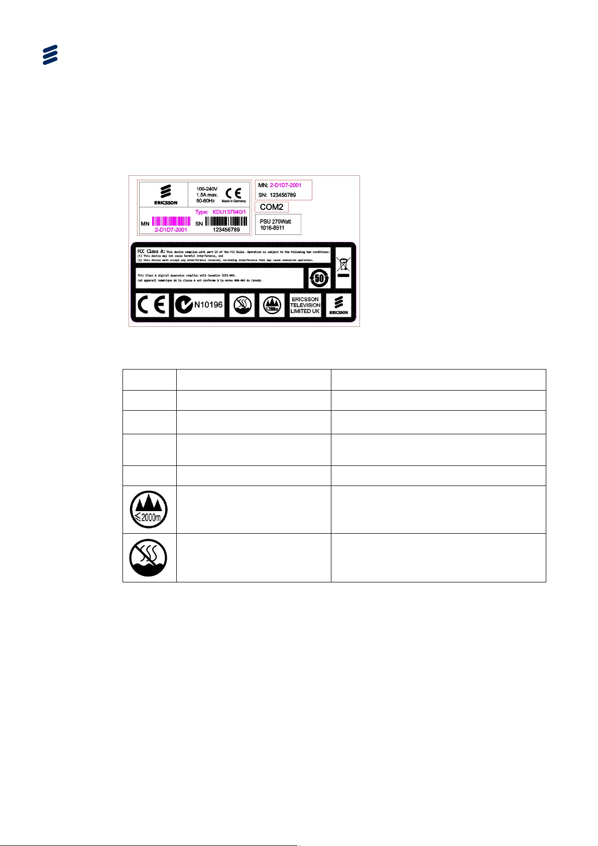
1.1.3 Equipment Label
1.1.3.1 Contents of the Label
On the equipment is an information label (Figure
1.1) which identifies the
configuration of the unit. The inclusion of options may affect the rear panel labeling.
Model: SVP 2000
Figure
T
Item Description
Model Identifies the product
Type
MN
1.1 Equipment Labeling
1.2 Equipment Labeling Description
able
Product Type
Manufacturing Number/Barcode
Note
A reference (Supply Object) which identifies
the build standard of each unit
Used for unit identification in the
manufacturing process
SN
Serial Number
Only used at altitude not
exceeding 2000m.
Only used in non-tropical
climate regions.
1.1.4 Firmware/Software Versions
This guide has been written to cover the functionality of the firmware/software
versions which are contained within the Device Software Version 3.0.
This guide continues to be relevant to subsequent build versions where the
functionality of the equipment has not changed. Where the build standard changes
the functionality, a new issue of this guide will be provided.
A unique number for unit identification
1-4
EN/LZT 790 0046/1 R1A
Page 13
etwo
(
1.2 SVP 2000 Video Processor
1.2.1 Summary of Features
1.2.1.1 SVP 2000 Video Processor DASH System
Introduction
Figure
1.2 shows a typical DASH scenario.
Encoder
A/V Stream
SDI)
Media
Presentation
MPEG-DAS
H
Unmanaged IP
N
rk
Media
Presentation
scription
De
Control GUI
Messaging
SVP2000/BAS/EN
Manifest File
GET ts
Reques
2
1
t t+8 t+16
t+24 t+32
Figure
1.2 Typical SVP 2000 DASH System
1.2.1.2 SVP 2000 Encoder (SVP2000/BAS/EN)
The key elements for the Encoder are as follows:
MPEG-DASH
Manifest File
GET ts
Reques
Decoder
Media
Presentation
Media
Presentation
Description
Messaging
SVP2000/BAS/RX
A/V Stream
(SDI)
Creating and storing the files, creating the manifest file (Media Presentation
Description), and then playing out the file.
The video enters the Encoder, either via an SDI or as a Transport Stream over a
GigE connector, it creates up to five profiles and a manifest file. Each of the
profiles is DASH segmented as a file.
The bit rates for the files stored are logged in the manifest file, which keeps a
record of each file segment available for transmission.
Supported modes are:
- SDI To MPEG-DASH
- SDI To RTP-TS
- MPEG-TS To MPEG-DASH MPEG-TS To RTP-TS 2 x SDI Inputs:
- Video: 2 x SD/HD-SDI Number of inputs: 2x SMPTE 259M.
- Video input size is automatically selected from the SDI video inputs
EN/LZT 790 0046/1 R1A
1-5
Page 14

Introduction
- Supports uncompressed 8-bit/10-bit digital video capture
- The device is able to process uncompressed SDI video input(s).
- Audio: eight embedded PCM stereo audio channels
Transport Stream input is supported
Choice of DASH or RTP/UDP output data network protocols
Encodes up to five profiles
ABR Encoder based on MPEG-4 AVC compression
Storage capability for simultaneous high quality file capture (requires license
SVP2000/SWO/EN/FI-ST)
Simple Web-based user interface (Internet Explorer 10, Firefox, Chrome)
Text messaging available between Encoder and Decoder
GigE IP interface
1RU x 19” chassis with compact form factor
Optional SMPTE 2022-2 FEC support
1.2.1.3 SVP 2000 Decoder (SVP2000/BAS/RX)
The key elements for the Decoder are as follows:
Rebuilding the transport stream (DASH)
The Encoder builds a manifest file (called the Media Presentation Description)
The MPD is transmitted periodically to the Decoder to show the media ready for
transmission from the Encoder. Depending on the feedback from the Decoder,
an appropriately encoded file segment is requested and transmitted by the
Encoder. The stream of file chunks fetched by the Decoder consists of different
sizes i.e. bit rates.
The incoming files are collated by the Decoder and re-encoded into a video that
is sent out either as a Transport Stream or over the SDI.
The bit rate of the encoded video can be defined by feedback from the Decoder.
Supported modes are:
- MPEG-DASH To SDI
1-6
- RTP-TS To SDI
- MPEG-DASH To MPEG-TS (only if the SVP2000/SWO/RX/TSIP license is
enabled)
- RTP-TS To MPEG-TS (only if the SVP2000/SWO/RX/TSIP license is
enabled)
1 x SDI Output:
EN/LZT 790 0046/1 R1A
Page 15

- Video: 1 x SD/HD-SDI
- Audio: 8 embedded PCM stereo audio channels
Professional Decoder based on MPEG-4 AVC Compression
Seamless switching between incoming streams
Simple Web-based user interface (Internet Explorer 10, Firefox, Chrome)
Text messaging available between Encoder and Decoder
Gige IP interface
1RU x 19” chassis with compact form factor
Optional SMPTE 2022-2 FEC support
1.2.2 Characteristics of an Unmanaged Network
Typically, the last mile link or DSL network offers no Quality of Service (QOS) and
has varying bandwidth capacity. It exhibits congestion limiting use for constant bit
rate (CBR) services. This results in Congestive Packet Loss because the network
is unable to support the amount of traffic it receives. There are, also, Transmission
Bit Errors resulting from transmission channel noise, distortion, signal weakness,
bit synchronization, or attenuation.
Introduction
As the available bandwidth varies over time, which could be due to a number of
reasons e.g. more people sharing the same bandwidth in fibre networks or rain fade
for Ka-band satellite services and Microwave links, the IP network exhibits
congestion.
When networks suffer congestion, this prevents the use of CBR services as the IP
network is unable to support the required bandwidth. There could also be some
transmission errors that are exhibited.
In practice, because there is a low probability of bit-error related packet loss, almost
all packet loss in terrestrial IP networks is caused by network congestion.
1.2.3 SVP 2000 Video Processor Solution
The driver for adopting this solution is either capital expenditure savings or new lines
of revenue.
High capital expenditure results from the occasional use of an expensive
Satellite uplink or an expensive high-capacity fibre link.
New lines of revenue can result from the ability to provide existing content over
cheaper links than other providers thereby enabling a viable business model.
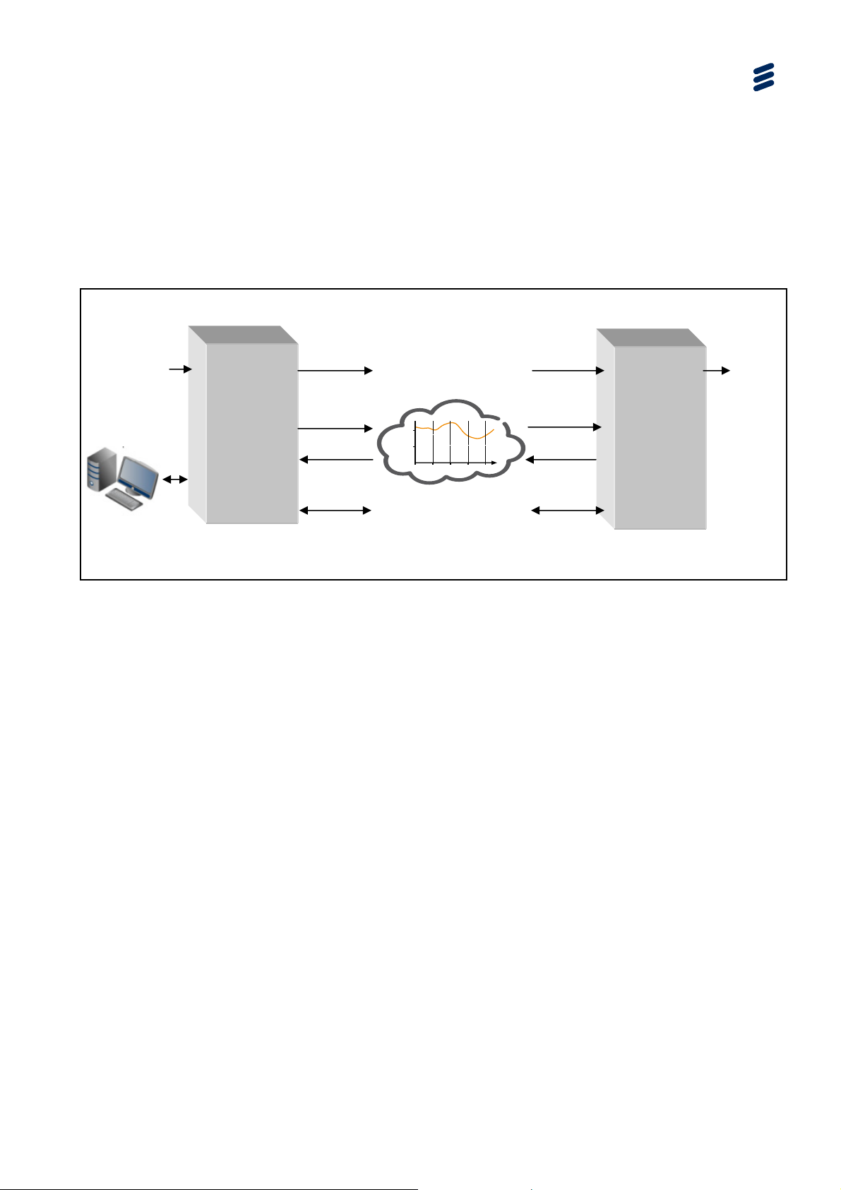
The basic concept is to exchange video from one location to another over an
unmanaged network (generally public IP).
EN/LZT 790 0046/1 R1A
1-7
Page 16

etwo
Introduction
Video
+
Audio
Figure 1.3 Basic SVP 2000 Video Processor Network Concept
Encoder
SVP2000/BAS/EN
2
1
t t+8 t+16
t+24 t+32
Unmanaged IP
rk
N
1.2.4 When to Use RTP/UDP Mode
In most cases, the SVP 2000 will use the ABR mode. However, there may be cases
where the use of RTP/UDP mode is preferable. These cases are:
1. Where there is guaranteed bandwidth available between the Encoder and
Decoder
2. Where latency between the Encoder and Decoder needs to be reduced
Decoder
Video
+
Audio
SVP2000/BAS/RX
3. If there is suspicion that there is a possibility of data corruption on the network –
enabling FEC would help protect against data corruption.
Note: There is the ability to add FEC to the ABR mode. Adding FEC will increase
latency. Therefore for most applications, ABR mode would be used.
4. ABR uses Transmission Control Protocol (TCP) protocol for transmission and
requires an acknowledgement for every packet transmitted. If
acknowledgements take a long time to be delivered, the protocol assumes
network congestion. For IP over satellite (KA Band), these acknowledgements
could be long and as such may not be usable.
Note: There is the
ability to do ABR over UDP instead of TCP. This should then
allow the use of IP networks over satellite bands.
Caution!
In RTP/UDP mode, only a single profile, fixed bit rate is transferred between the
Encoder and the Decoder.
1-8
EN/LZT 790 0046/1 R1A
Page 17

1.3 SVP 2000 Video Processor Basics
1.3.1 Key System Elements
The key elements of the DASH system are:
the Encoder
- the files created and stored
- the manifest file is compiled
- the file playout
the Decoder
- rebuild of the transport stream
- control of the rate of media transfer
Introduction
The video comes into the Encoder, either via SDI or as a Transport Stream over a
GigE connector, it creates up to five profiles and a manifest file. Each video profile is
DASH segmented as a file.
The bit rates for each segmented file available for transmission are recorded in the
manifest file.
The Decoder monitors the receive data rate (measured time for known file size).
Depending on the request from the Decoder, the Encoder transmits appropriately
encoded file segments.
The stream of file chunks fetched by the Decoder consists of different sizes i.e. bit
rates. The incoming files are then collated by the decoder and re-encoded into a
video that is sent out either as a transport stream or over the SDI. The bit rate of the
encoded video can also be defined at the Decoder
1.3.2 Video Profiles
The video stream input is fed into the Encoder which creates a number of different
bit rate profiles of the same video. At the Decoder, the lowest bit rate profile is pulled
and the data transfer speed over the network is checked. If the data transfer is
quicker than the playout time of the video, the Decoder requests a higher bit rate for
the segment. If this gets through quicker than the playout time, the Decoder
requests an even higher rate profile. Eventually, a requested profile will fail to get
though in the playout time. At this point, the Decoder requests the lower rate.
EN/LZT 790 0046/1 R1A
1-9
Page 18

Introduction
The amount of data that can be transferred across a network may change because
the bandwidth changes over time. However, because the Decoder is continuously
monitoring the amount of data it can receive through the network, the encoded bit
rate is managed (using profiles) such that there will be video delivered through the
network. The transport stream is rebuilt from the file segments created using the
appropriate video profiles.
1.3.3 SVP 2000 Video Processor Operating Modes
There are two modes of operation for the SVP 2000:
Dynamic Adaptive Streaming over HTTP (MPEG-DASH1)
This uses the MPEG-DASH format whereby the incoming video is encoded into
multiple bit rates files (profiles) of small playout times (generally two seconds).
Each of these files is then presented as available to the decoder. The decoder,
depending upon the available bandwidth, selects the appropriate size file that it
can extract from the encoder so that it can then be recreated into video without
any gaps. As the video bit rate is adapted for the available network, this
methodology is generally referred to as Adaptive Bit Rate (ABR). This is
probably the most common method that will be used for unmanaged networks.
Real-time Transfer Protocol (RTP) / User Datagram Protocol (UDP) unicast or
multicast.
Over an IP network, there are a number of protocols that can be run. The ABR
method uses the TCP protocol whereby an acknowledgement is provided for
every delivered packet. For the RTP/UDP method, a packet is transmitted and
assumed that it will be delivered i.e. there is no guarantee of delivery. Although
this may appear to be not a secure transmission method, it is the method that is
best suited for video delivery. As there is no acknowledgement for packet
receipt, there is the option of FEC (Forward Error Correction) to ensure that if
there is any corruption in the data packet then FEC can be used to recover the
video.
The availability of the RTP-TS mode is governed by the license on the unit.
Caution!
Both the Encoder and Decoder need to operate in the same mode.
1
Also known as DASH
1-10
EN/LZT 790 0046/1 R1A
Page 19

1.3.4 Bandwidth Efficiency Over Unmanaged Networks (DASH)
This SVP 2000 Video Processor provides a solution for maximizing bandwidth
efficiency over unmanaged networks (where bandwidth of unmanaged network is
variable).
They work as a pair allowing the transport of high-quality video material over the
Internet using DASH.
The Encoder (SVP2000/BAS/EN) takes an SDI input and provides a segmented
DASH output.
The Decoder (SVP2000/BAS/RX) takes this DASH stream and decodes it back
to an SDI output.
1.3.5 Networks With Some Guaranteed Bandwidth (RTP/UDP)
This SVP 2000 configuration offers RTP/UDP with SMPTE 2022-2 Forward Error
Correction (FEC) for recovering IP packets on lossy networks (where there is some
guarantee of bandwidth availability on the unmanaged network).
Introduction
The SVP 2000 Video Processor Encoder and Decoder work as a pair allowing the
transport of high-quality video material over the Internet using RTP/UDP with
Forward Error Correction (FEC).
The Encoder (SVP2000/BAS/EN) takes an SDI input and provides an RTP
stream.
The Decoder (SVP2000/BAS/RX) takes this RTP stream and decodes it back to
an SDI output.
EN/LZT 790 0046/1 R1A
1-11
Page 20

Introduction
1.4 Characteristics of IP Transfer Mechanisms
1.4.1 Quality of Service
Scalable video systems need multi-rate delivery to ensure optimal Quality of
Service. An SVP 2000 Video Processor pair is able to generate up to five variant
video streams. To cover a wide range of bandwidth use cases, those variant
streams typically have decreasing bit rate, resolution and/or frame rate.
Note: Multi rate audio is not supported.
The SVP 2000 Video Processor pair is able to seamlessly switch between those
variants streams, to resist network glitches and bandwidth changes.
1.4.2 Video Latency
In the contribution market, there are basically two types of content:
one that CANNOT tolerate any latency e.g. major sporting events like Olympics,
World cups, and
content that CAN tolerate latency like pre-packaged programs, tier-2 sports
content, PEG (Public, Educational and Government) channels.
The SVP 2000 solution may be applicable for some markets (e.g. breaking news)
where live streams are required. However predominantly it is aimed where delays in
video are acceptable.
The SVP 2000 introduces some delays and as such from the time the video is
received, encoded, transmitted, decoded and pictures obtained, there will be some
delays.
1.4.3 Typical Use Cases
The following lists some of the uses for SVP 2000 system:
Regional News Bureaus
- Broader news coverage
A sub-set of regional news case is breaking news. Here the operator would
like to get a van out to the location. The reporter/camera operator would
connect the SVP 2000 using a public network back to the studio which could
even be a 3G network. As the IP network bandwidth could be variable, the
quality of the contributed video would vary. This may be fine for the initial
news story as they would be on site while events are happening. However,
the unit is able to store the highest profile on an attached USB. Once the
story has been contributed, the highest profile can be uploaded in non-real
time back to the studio. In this way the highest quality content is available for
subsequent bulletins.
1-12
EN/LZT 790 0046/1 R1A
Page 21

Introduction
- Interconnects facilities in remote regions
The goal is for each of the regions to provide news back to the main studios
as cheaply as possible. Thus allowing facilities to interconnect remote
regions. These regions may want to contribute their few minutes of news as
a packaged program thus providing broader news coverage.
Tier 2 Sports Coverage
- Extends coverage of regional events
The SVP 2000 provides a cost effective way to get content distributed. For
example, an operator could have valuable content and therefore having an
affordable contribution or distribution system would provide a new revenue
stream.
- Delivery of content over unmanaged networks
Another application could be the use of this technology at local sports
venues to feed minor sporting events like college football or minor league
baseball games or allows coverage of some of the niche events where
putting in a dedicated link would be cost prohibitive.
Content contribution from remote sites
- Provides cost effective mechanism for contribution
Third use case is where an operator is mandated to carry content from
remote sites e.g. must carry channels, PEG channels or some niches
channels. These channels again may not be of higher value to the operator
but they have to carry them.
- Allows use of standard public IP networks to reduce costs
Putting in expensive links like satellite or fibre may be prohibitive. SVP 2000
could offer a cost-effective alternative
Backup
- Setup as a backup link in the event of an emergency.
An operator could have an expensive primary link, but could use the SVP
2000 over an IP link in the event of an emergency thus providing a cost
effective backup link.
EN/LZT 790 0046/1 R1A
1-13
Page 22

A
Introduction
1.5 Guided Tour
1.5.1 SVP 2000 Video Processor Front Panel
Figure 1.4 shows the front panel of the SVP 2000 Video Processor Encoder
(SVP2000/BAS/EN) and Decoder (SVP2000/BAS/RX). The front panel for both units
is the same.
Figure
Power Indicator
HDD Ac
1.4 Front View of the SVP 2000 Video Processor
tivity Indicator
There are no controls or connectors at the front panel. However access to the power
switch requires removal of the front panel (see Chapter 3 Getting Started).
There are two indicators visible at the front panel.
Table
1.3 Description of Indicators
State Indication
On Green LED Power on
On Amber LED
Comment
HDD ac
during operation of the unit
Power SwitchAir Filter
tivity. This LED may flicker on and off
ir Filter
USB Ports USB Ports LED Indicators
Figure
1.5 Items Behind the Front Panel
There are two indicators and the unit power supply switch located behind the front
panel. (The indicators are visible through the front panel – see Table
1.3.)
Note: The Power button is held for several seconds to start the unit, or can also be
used to power off the unit.
1-14
EN/LZT 790 0046/1 R1A
Page 23

Adap
Adap
1.5.2 Encoder (SVP2000/BAS/EN) Rear Panel
Figure 1.6 shows the rear panel of the SVP 2000 Video Processor Encoder. It
provides a single AC (100-240 V, 50-60 Hz) power supply connector along with the
dual input HD/SDI card. There are three Ethernet adaptors, Adaptors 0 and 1 are
used for control and data, while Adaptor 2 has a fixed IP address for configuration
only.
Introduction
Adaptor 2
tor 1
USB Connectors
Adaptor 0
SB Connectors
U
Figure
1.6 Rear View of the SVP 2000 Video Processor Encoder
Notes: All other connectors are for factory use only.
One USB st
orage device may be connected to any of the USB connectors
on the SVP 2000 Encoder for use with the File Storage license option as an
alternative to using one of the front panel connectors. The USB storage
device must be NTFS (New Technology File System) formatted.
1.5.3 Decoder (SVP2000/BAS/RX) Rear Panel
RX0 HD/SD SDI Input
RX1 HD/SD
SDI Input
AC Power
Supply
Figure
Figure 1.7 shows the rear panel of the SVP 2000 Video Processor Decoder. It
provides a single AC (100-240 V, 50-60 Hz) power supply connector along with the
HD/SDI output card. There are three Ethernet adaptors, Adaptors 0 and 1 are used
for control and data, while Adaptor 2 has a fixed IP address for configuration only.
Adaptor 2
tor 1
USB Connectors
Adaptor 0
USB Connector
1.7 Rear View of the SVP 2000 Video Processor Decoder
Note: All other connectors are for factory use only.
AC Power
Supply
HD/SD SDI Output
EN/LZT 790 0046/1 R1A
1-15
Page 24

Introduction
BLANK
1-16
EN/LZT 790 0046/1 R1A
Page 25

2 Installing the Equipment
Chapter 2
Contents
2.1 Read This First! .................................................................................... 2-3
2.1.1 Handling ...............................................................................................2-3
2.1.2 Installing the Equipment ....................................................................... 2-3
2.1.3 Lifting....................................................................................................2-3
2.1.4 Site Requirements................................................................................2-3
2.1.4.1 Power Supplies..................................................................................... 2-3
2.1.4.2 Environment .........................................................................................2-3
2.2 Preliminary Checks............................................................................... 2-3
2.2.1 Mechanical Inspection..........................................................................2-3
2.2.2 Moving the Equipment Safely............................................................... 2-4
2.3 Installing the Equipment ....................................................................... 2-4
2.3.1 Fixing and Rack Mounting....................................................................2-4
2.3.2 Ventilation............................................................................................. 2-4
2.3.2.1 Openings in the Chassis....................................................................... 2-5
2.3.2.2 Care in Positioning ...............................................................................2-5
2.3.2.3 Protection from Moisture ......................................................................2-6
2.3.3 Installing Cables - Safety...................................................................... 2-6
2.4 EMC Compliance Statements .............................................................. 2-6
2.4.1 EN 55022/CISPR22.............................................................................. 2-6
2.4.2 FCC ...................................................................................................... 2-7
2.5 AC Supply Operation............................................................................ 2-7
2.5.1 AC Power Supply Cord......................................................................... 2-8
2.5.2 Connecting the Equipment to the AC Power Supply ............................ 2-8
2.5.3 Protective Earth/Technical Earth ..........................................................2-8
2.6 Rear Panel Signal Connectors ............................................................. 2-8
2.6.1 SVP 2000 Encoder HD/SD SDI Interface............................................. 2-8
2.6.2 SVP 2000 Decoder SDI Interface......................................................... 2-9
2.6.3 SVP 2000 GigE IP Interface.................................................................2-9
2.6.4 SVP 2000 USB Interface....................................................................2-10
2.6.4.1 Archiving Option (SVP2000/SWO/EN/FI-ST) ..................................... 2-10
2.6.4.2 Firmware Upgrade.............................................................................. 2-10
EN/LZT 790 0046/1 R1A
2-1
Page 26

Installing the Equipment
List of Figures
Figure 2.1
Unit Ventilation ..................................................................................... 2-5
Figure 2.2 AC Supply Connector........................................................................... 2-7
List of Tables
Table 2.1
Cable Types......................................................................................... 2-6
Table 2.2 SVP 2000 Encoder SDI Interface ........................................................ 2-9
Table 2.3 SVP 2000 Decoder SDI Interface ........................................................ 2-9
Table 2.4 SVP 2000 Ethernet Interface ............................................................. 2-10
Table 2.5 Ethernet LEDs.................................................................................... 2-10
2-2
EN/LZT 790 0046/1 R1A
Page 27

2.1 Read This First!
2.1.1 Handling
The equipment must be handled and installed carefully and thoughtfully to prevent
safety hazards and damage.
2.1.2 Installing the Equipment
Ensure the personnel designated to fit the unit have the appropriate skills and
knowledge. If in any doubt, contact Ericsson Customer Services (see Preliminary
Pages for contact details).
Installation of the product should follow these instructions, and should only use
installation accessories recommended by the manufacturers. When rack mounted,
this equipment must have shelf supports as well as being fixed at the front panel.
Installing the Equipment
Do not use this product as a support for any other equipment.
2.1.3 Lifting
In some circumstances the unit might be awkward to lift. In which case, do not
attempt to lift or move it without proper assistance or equipment. If in doubt, seek
assistance.
2.1.4 Site Requirements
2.1.4.1 Power Supplies
See Annex B Technical Specification for a full specification.
2.1.4.2 Environment
See Annex B, Technical Specificat
product in areas of high humidity or where there is danger of water ingress.
2.2 Preliminary Checks
ion for a full specification. Do not install this
2.2.1 Mechanical Inspection
When taking delivery of a unit check the equipment items delivered against the
enclosed delivery note. Inspect the equipment for damage in transit. If in doubt,
contact Ericsson Customer Services (see Preliminary Pages).
EN/LZT 790 0046/1 R1A
2-3
Page 28

Installing the Equipment
Note: Do not remove the top cover of this equipment as doing so may invalidate
any warranties, cause a safety hazard and/or affect the EMC performance.
It may also invalidate any safety tests. Check with Ericsson Customer
Services beforehand.
2.2.2 Moving the Equipment Safely
Do not place this product on an unstable cart, stand, bracket, or
table. The product may fall, causing serious injury and serious
damage to the product. Use only with a cart, stand, bracket or table
recommended by Ericsson.
An appliance and cart combination should be moved with care. Quick stops,
excessive force, and uneven surfaces may cause the appliance and cart
combination to overturn. Do not move or carry the equipment whilst it is still
connected to the supply or other leads, is live, or is in operation.
2.3 Installing the Equipment
2.3.1 Fixing and Rack Mounting
The equipment is designed for fixed use only in a standard 19-inch rack. When
installed in a rack, it should be secured using the fixing brackets. Ensure it is firmly
and safely located and it has an adequate free-flow of air.
Slide the unit onto the chassis supports and affix to the rack by means of an M6 x
18 mm panhead screw in each corner.
A freestanding unit should be installed on a secure horizontal surface where it is
unlikely to be knocked or its connectors and leads disturbed.
2.3.2 Ventilation
Never push objects of any kind into the openings of the equipment as they may
touch dangerous voltage points or short out parts that could cause a fire or electric
shock.
Prevent spillage of any liquid on the product.
Warnings!
2-4
EN/LZT 790 0046/1 R1A
Page 29

Openings in the cabinet are provided for ventilation and to ensure reliable operation
of the product and protection from overheating. These openings must not be
blocked or covered. Clean filters periodically.
This product should never be placed near or over a radiator or other source of heat.
This product should not be placed in a built-in installation such as a rack unless
proper ventilation is provided or the instructions have been adhered to.
Do not install equipment so that the air intake of one aligns with the outlet on
another. Provide baffles and adequate spacing.
2.3.2.1 Openings in the Chassis
Cool air is drawn into the unit from the front, passes through the unit and exits via
the rear panel openings.
Installing the Equipment
Cautions!
Figure
2.1 Unit Ventilation
2.3.2.2 Care in Positioning
The equipment should never be placed near or over a radiator or other source of
heat. It should not be placed in a built-in installation such as a rack unless proper
ventilation is provided and the instructions have been adhered to.
Caution!
Allow at least 40 mm free air-space at each side of the equipment to ensure
adequate cooling. Racks containing stacked equipment may need to be forced aircooled to reduce the ambient temperature within the rack.
EN/LZT 790 0046/1 R1A
2-5
Page 30

Installing the Equipment
2.3.2.3 Protection from Moisture
Do not install this equipment in areas of high humidity or where there is a danger of
water ingress.
2.3.3 Installing Cables - Safety
Power supply cables should be routed so that they are not likely to be walked on or
pinched by items placed upon or against them. Pay particular attention to cables at
plugs, convenience receptacles, and the point where they exit from the appliance.
Do not run AC power cables in the same duct as signal leads. Do not move or install
equipment whilst it is still attached to the mains supply. Ensure safety and ESD
precautions are observed while connecting equipment.
Warning!
The signal cable types (or similar) described in the following table are those
recommended by Ericsson in order to maintain EMC compliance of the equipment.
2.1 Cable Types
Table
Signal Type Connector Cable
Ethernet (Control) RJ-45 CAT 5E Data Cable S-FTP
Ethernet (Data) RJ-45 CAT 5E Data Cable S-FTP
HD-SDI In (Digital Video
Input)
SDI In (Digital Video Input) BNC
BNC Belden 1694A
Belden 1694A
Or
Canford Audio BBC 1/3 PSF (type 2
video cable)
2.4 EMC Compliance Statements1
2.4.1 EN 55022/CISPR22
This is a Class A product. In a domestic environment this product may cause radio
interference in which case the User may be required to take adequate measures.
1
The EMC information was correct at the time of manufacture.
2-6
EN/LZT 790 0046/1 R1A
Page 31
2.4.2 FCC
This equipment has been tested and found to comply with the limits for a Class A
digital device, pursuant to Part 15 of the FCC Rules. These limits are designed to
provide reasonable protection against harmful interference when the equipment is
operated in a commercial environment.
This equipment generates, uses and can radiate radio frequency energy and, if not
installed and used in accordance with the Reference Guide, may cause harmful
interference to radio communications. Operation of this equipment in a residential
area is likely to cause harmful interference in which case the User will be required to
correct the interference at their own expense.
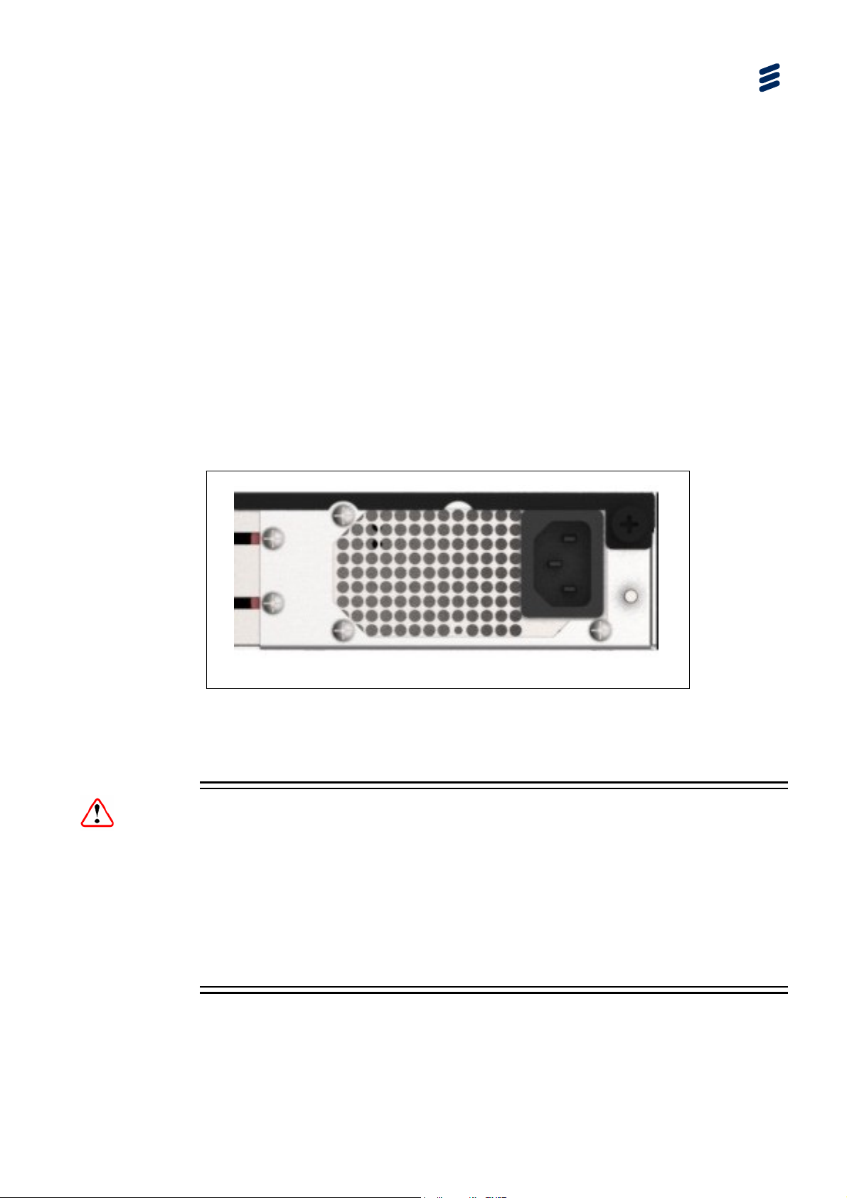
2.5 AC Supply Operation
Ericsson products are fitted with power supplies suitable for all worldwide mains
supply voltages (100 - 240 V AC). The full Technical Specification is given in Annex
B, Technical Specification.
Installing the Equipment
Figure
2.2 AC Supply Connector
Note: The SVP2000 does not have a user replaceable fuse.
Warnings!
The SVP 2000 should only be operated from the type of power source indicated on
the marking label. If you are not sure of the type to your business, consult your
appliance dealer or local power company. Do not overload wall outlets and
extension cords as this can result in a risk of fire or electric shock.
Although these product
disconnect the power supply the appliance coupler must be removed. The appliance
coupler should therefore be accessible.
s are fitted with an AC power supply switch, to fully
EN/LZT 790 0046/1 R1A
2-7
Page 32

Installing the Equipment
2.5.1 AC Power Supply Cord
A mains supply cord is supplied with this product. It is fitted with a moulded plug
suitable for the region specified at the time of ordering. Please check that it is
suitable for the country in which the product is to be used.
2.5.2 Connecting the Equipment to the AC Power Supply
Connect the mains lead to the equipment and then to the local supply. Then switch
the unit on using the power switch on the front panel.
2.5.3 Protective Earth/Technical Earth
Warnings!
This equipment must be correctly earthed through the moulded plug supplied. If the
local mains supply does not have an earth conductor do not connect the equipment.
Contact Ericsson Customer Services for advice.
Before connecting the equipment to the supply, check the supply requirements in
Annex B, Technical Specification.
This equipment has a Technical Earth terminal located at the rear panel. Its use is
recommended but is NOT a Protective earth for electric shock protection. The
terminal is provided for the following:
Ensures all equipment chassis fixed within a rack are at the same technical
earth potential. To do this, connect a wire between the technical earth terminal
and a suitable point on the rack.
Eliminates the migration of stray charges when connecting between equipment.
2.6 Rear Panel Signal Connectors
Signal connections are made via connectors on the rear panel. These are shown in
the following sections. Full technical specifications for the connections are given in
Annex B, Technical Specification.
2.6.1 SVP 2000 Encoder HD/SD SDI Interface
2-8
Standard and High Definition digital video can be input
via the two 75 Ω female BNC connectors at the rear
panel.
RX1 RX0
This interface is setup using the SDI Input Details
page under the Advanced tab.
EN/LZT 790 0046/1 R1A
Page 33

Installing the Equipment
This input is terminated in 75 .
2.2 SVP 2000 Encoder SDI Interface
Table
Item Specification
Connector type
Connector designation RX1 (left-hand connector)
Pin-outs Centre
Shield
75 female BNC
RX0 (right-hand connector)
Input
Ground/Chassis
2.6.2 SVP 2000 Decoder SDI Interface
Standard and High Definition digital video is
output via the right-hand 75 Ω female BNC
connector at the rear panel.
This interface is setup using the SDI Output Details
page under the Advanced tab.
2.3 SVP 2000 Decoder SDI Interface
Table
Item Specification
Connector types
Connector designation (right hand connector)
75 female BNC
HD/SD SDI
Output
Pin-outs Centre
Shield
Input
Ground/Chassis
2.6.3 SVP 2000 GigE IP Interface
Three 8-pin, RJ-45 connectors provide 1000Base-T
Ethernet ports. Adaptors 0 and 1 are used for
control and data, while Adaptor 2 has a fixed IP
address for configuration only.
Notes: Typically, Adaptor 0 for control and
Adaptor 1 for data, although any port can
be used as required.
Adaptor 2 has a fixed address so that the
unit is always accessible. It can be
changed during a session of use but will
revert to the default on a repower cycle.
This interface is setup using the Publishing or TS Input tabbed pages on the
Encoder GUI and TS Input tabbed page on the Decoder GUI.
ADAPTOR
2
ADAPTOR
1
ADAPTOR
0
EN/LZT 790 0046/1 R1A
2-9
Page 34

Installing the Equipment
Table 2.4 SVP 2000 Ethernet Interface
Item Specification
Connector type 8-way, RJ-45
Connector designation Adaptor 0
Adaptor 1
Adaptor 2
Pin-outs
Pin Signal Pin Signal
1 Tx Out (+) 4-5 Not connected
2 Tx Out (-) 6 Rx In (-)
3 Rx In (+) 7-8 Not connected
Table 2.5 Ethernet LEDs
State Indication Comment
Left LED (as viewed from the connector side):
Off No active link
Green Full duplex link present Flashing for activity
Yellow Half duplex link present Flashing for activity
Right LED (as viewed from the connector side):
Off 10 Mbps
Green 100 Mbps
2.6.4 SVP 2000 USB Interface
2.6.4.1 Archiving Option (SVP2000/SWO/EN/FI-ST)
High-resolution file storage on an attached USB. Operators can transmit video to the
Decoder and let the Encoder adapt the bit rate to suit the network conditions. So at
the Decoder site the video quality could be variable.
Using this feature, the highest resolution video is stored on the locally attached USB
disk while simultaneously transmitting the ABR video to the Decoder.
Once the transmission is completed, the stored file (Transport Stream) can be
uploaded or fetched from the remote site. Thus at the studio, the highest resolution
video is available for subsequent transmissions.
2.6.4.2 Firmware Upgrade
Firmware up
fresh USB key. See Chapter 6 for more details.
dates are provided as USB keys, or as files which must be placed on a
2-10
EN/LZT 790 0046/1 R1A
Page 35

3 Getting Started
Chapter 3
Contents
3.1 How to Connect Up the Units ...............................................................3-3
3.2 Powering the SVP 2000 Video Processor ............................................3-4
3.2.1 Before Powering Up .............................................................................3-4
3.2.2 Powering Up .........................................................................................3-4
3.2.3 Powering Down ....................................................................................3-5
3.3 Configuration Order for a New Unit ......................................................3-5
3.4 How to Configure the SVP 2000 Using the Web GUI........................... 3-6
3.4.1 Using the Web Graphical User Interface ..............................................3-6
3.4.2 Appearance and General Features ...................................................... 3-6
3.4.3 Navigation Area ....................................................................................3-7
3.4.4 Accessing the Graphical User Interface ............................................... 3-7
3.4.5 Default IP Addresses............................................................................ 3-7
3.5 Applying the License to the SVP 2000 ................................................. 3-8
3.6 Setting the Unit IP Address ..................................................................3-9
3.7 Starting and Stopping the SVP 2000 Encoder ...................................3-10
3.8 Starting the SVP 2000 Decoder .........................................................3-11
3.9 Messaging .......................................................................................... 3-12
3.10 Upgrading the SVP 2000 Unit ............................................................3-12
List of Figures
Figure 3.1
Figure 3.2 Items Behind the Front Panel ...............................................................3-4
Figure 3.3 Appearance and General Features ...................................................... 3-6
Figure 3.4 Initial License Page ..............................................................................3-8
Figure 3.5 Encoder SDI Input Page..................................................................... 3-10
Figure 3.6 Decoder DASH Input Page................................................................. 3-11
Figure 3.7 Messaging Page................................................................................. 3-12
List of Tables
Table 3.1
Table 3.2 RF C3330 IP Address Restrictions....................................................... 3-9
EN/LZT 790 0046/1 R1A
Typical SVP 2000 Video Processor Connections................................. 3-3
SVP 2000 Default IP Addresses ..........................................................3-8
3-1
Page 36

Getting Started
BLANK
3-2
EN/LZT 790 0046/1 R1A
Page 37

(
)
3.1 How to Connect Up the Units
See Chapter 2, Installing the Equipment for all connector details.
SVP 2000 ENCODER SVP 2000 DECODER
SDI CARD
RX0 (Right)
Serial Digital Interface
RX1 (Left)
SDI CARD
RX0 (Right)
Getting Started
Serial Digital Interface
Figure
Configuration
100BaseT
Adaptor 2
(Fixed A
ddress)
Data
Adaptor 1
100BaseT
100BaseT
Control
1000Base-T
USB Memory
Stick
Adaptor 0
Firmware Upgrade
or Archive
USB
1000Base-T
USB Memory
Stick
3.1 Typical SVP 2000 Video Processor Connections
Notes: Transport Stream input needs to be inserted via either Control or Data port.
Transport Stream out needs to be co
or Control port.
Configuration
Adaptor 2
Fixed Address
Data
Adaptor 1
Control
Adaptor 0
Firmware Upgrade
USB
nfigured for output on either the Data
Typically, Adaptor 0 is for control and Adaptor 1 is for data, although any
port can be used as required.
EN/LZT 790 0046/1 R1A
3-3
Page 38

Getting Started
3.2 Powering the SVP 2000 Video Processor
3.2.1 Before Powering Up
Before powering up the SVP 2000 Video Processor, check that:
1. The unit has been installed in a suitable location.
2. The unit has been connected to external equipment and power supply, as
required.
3. The power supply has been checked and a good earth provided.
3.2.2 Powering Up
The unit supply switch is located behind the front panel.
Figure
3.2 Items Behind the Front Panel
To power up the unit:
With all signal and power cables connected as required, turn on the unit using
1.
the power switch. The SVP 2000 executes a series of power-up initialisation and
self-test routines.
Note: The boot time for the unit is approximately one minute.
2. Confirm that the green LED is lit showing that the unit is receiving power.
Caution!
This equipment should not be operated unless the cooling fans are working and
there is free-air flow around the unit.
3-4
EN/LZT 790 0046/1 R1A
Page 39

3.2.3 Powering Down
To power down the SVP 2000, operate the switch behind the front panel.
The SVP 2000 can also be powered down through the GUI.
3.3 Configuration Order for a New Unit
1. Connect a control PC to adaptor 0 or 1.
2. Connect the power cable to the unit.
3. Power up the unit.
4. Using a web browser on the control PC, go to the connected adaptor’s IP
address.
5. Load the license for the unit
6. Update the IP addresses for Adaptor 0 and Adaptor 1
Getting Started
7. Connect Adaptor 0 and Adaptor 1 to the control and data networks as required.
8. Connect the baseband signal cables to/from the unit as required.
9. Configure the unit (as per the Reference Guide).
10. Start the Encode or Decode process.
EN/LZT 790 0046/1 R1A
3-5
Page 40

Getting Started
3.4 How to Configure the SVP 2000 Using the Web GUI
3.4.1 Using the Web Graphical User Interface
The SVP 2000 is designed to be configured and controlled by its own web graphical
user interface (GUI).
This section describes the functions and elements of the GUI
3.4.2 Appearance and General Features
The appearance and the main components of the Graphical User Interface are
shown in Figure
The header contains the Company Logo, the Model Name and the Unit Name, the
Version number and the Output Status Indicator.
Tab
Navigation Area
3.3.
First Tier Tabs
Second Tier Tabs
Header
(Tabbed) Page
Figure
3-6
3.3 Appearance and General Features
EN/LZT 790 0046/1 R1A
Page 41

3.4.3 Navigation Area
The SVP 2000 is controlled through five different web pages (or tabs), each of them
responsible for a well-defined control task. The pages are accessed through the top
tier tabs in the Navigation area.
Displayed via the Advanced tab are a collection of tabbed pages associated with
setting up the unit and accessing unit information.
3.4.4 Accessing the Graphical User Interface
The Ethernet adaptor ports are used to connect the unit to a control computer for
control through a web browser.
The web browser Graphical User interface (GUI) is designed to configure, control
and monitor the unit and can be run on any Personal Computer (PC) or laptop on
the same network as the SVP 2000 using a suitable web browser.
The following web browsers have been tested:
Getting Started
Microsoft Internet Explorer (IE10)
Mozilla Firefox (28.0)
Google Chrome (34.0)
To access the Web Browser GUI:
1. Open a web browser session on the control PC.
2. Enter the IP address (assigned to the connected Network Adaptor) into the
address field of the Web browser.
3. If the network is correctly configured, the web interface page should be
automatically loaded and displayed. The unit can be configured and monitored
as required.
3.4.5 Default IP Addresses
The Control Computer must be located on the same sub-network as the SVP 2000
(Management Network). You may need to change the Management Computer IP
settings for this: IP address, netmask, and gateway. Unless stated otherwise at
delivery, SVP units have, by default, the following sub-networks at startup:
Caution!
As all SVP 2000s initially have the same IP addresses, they should not be switched
on at the same time as this may result in data conflict.
EN/LZT 790 0046/1 R1A
3-7
Page 42
Getting Started
Table 3.1 SVP 2000 Default IP Addresses
Ethernet Connector Default Address
Adaptor 0 192.168.1.1/255.255.255.0
Adaptor 1 192.168.2.1/255.255.255.0
Adaptor 2 192.168.3.1/255.255.255.0
Notes: Adaptor 2 has a fixed address so that the unit is always accessible. It can
be changed during a session of use but will revert to the default on a
repower cycle.
Adaptor 2 only allows control access, it should only be used to determine or
update the IP address configuration of Adaptor 0 and 1.
The control network and data networks should not conflict. It is suggested
that the ranges for these networks are in the Private-Use Networks as listed
in Table
3.2. IP Address range 192.168.10.x (subnet 255.255.255.0) is
used for internal unit communications, so should not be used for external
communications.
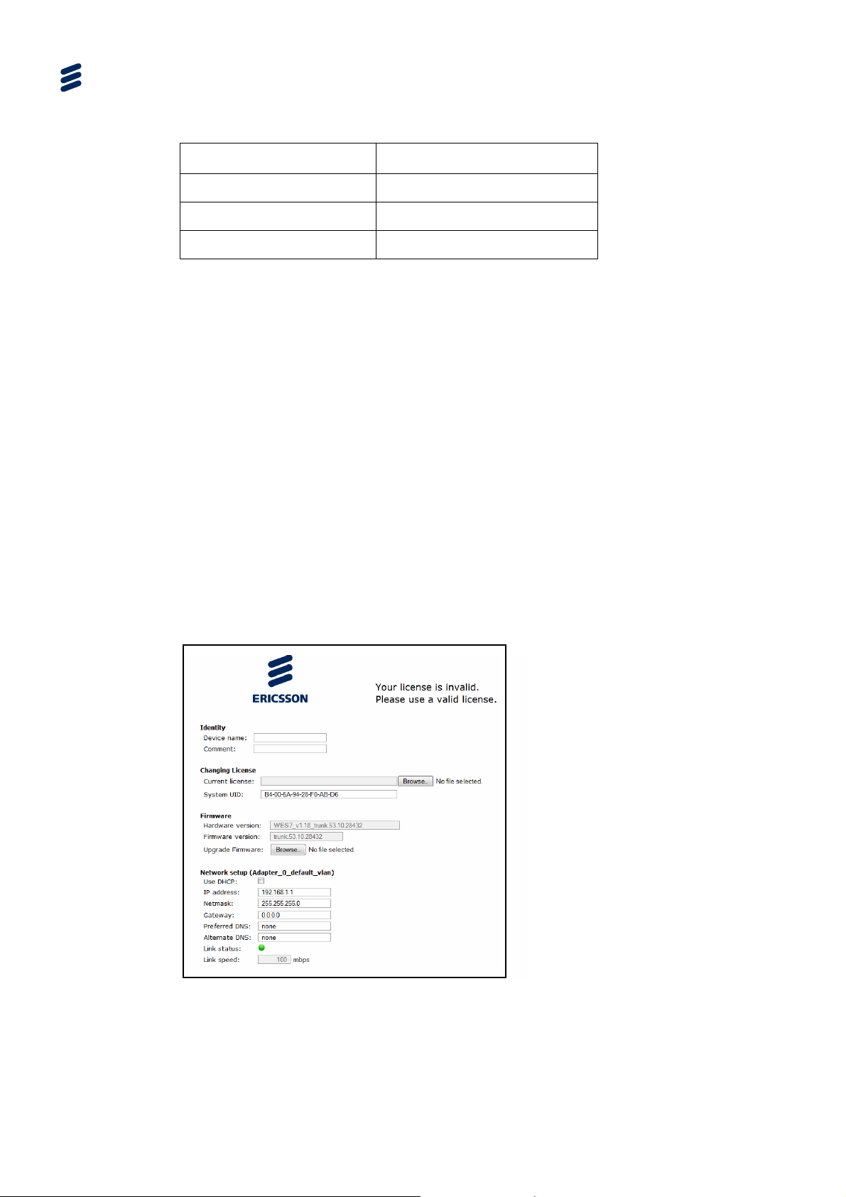
3.5 Applying the License to the SVP 2000
The SVP 2000 is by default delivered in a non-licensed state and requires
installation of the license to operate.
The license is installed via the web interface.
3-8
Figure
Select the license via th
3.4 Initial License Page
e Browse button, and upload the *.lic file associated with the
System UID.
EN/LZT 790 0046/1 R1A
Page 43

3.6 Setting the Unit IP Address
Setting the IP address of a unit is accomplished using the web interface menus.
To set the IP address of the unit(s):
1. Ensure the unit is fully powered up and unit initialisation is complete.
2. Using the web interface, navigate to the Advanced, Network tab.
3. Set the required IP address settings for Adaptors 0 and 1.
4. Press the Apply button to accept the changes (Note that this change may result
in the unit being on an unreachable network from the control PC)
IP addresses on the unit must adhere to the range of restrictions specified in
RFC3330.
3.2 RF C3330 IP Address Restrictions
Table
Block Present Use Reference
Getting Started
0.0.0.0/8 This Network [RFC1700, p4]
10.0.0.0/8 Private-Use Networks [RFC1918]
14.0.0.0/8 Public-Data Networks [RFC1700, p181]
24.0.0.0/8 Cable Television Networks ---
39.0.0.0/8 Reserved but subject to allocation [RFC1797]
127.0.0.0/8 Loopback [RFC1700, p5]
128.0.0.0/16 Reserved but subject to allocation ---
169.254.0.0/16 Link Local ---
172.16.0.0/12 Private-Use Networks [RFC1918]
191.255.0.0/16 Reserved but subject to allocation ---
192.0.0.0/24 Reserved but subject to allocation ---
192.0.2.0/24 Test-Net ---
192.88.99.0/24 6to4 Relay Anycast [RFC3068]
192.168.0.0/16 Private-Use Networks [RFC1918]
198.18.0.0/15 Network Interconnect Unit Benchmark Testing [RFC2544]
223.255.255.0/24 Reserved but subject to allocation ---
224.0.0.0/4 Multicast [RFC3171]
240.0.0.0/4 Reserved for Future Use [RFC1700, p4]
EN/LZT 790 0046/1 R1A
3-9
Page 44

Getting Started
Note: The IP addresses on the Adaptors must not conflict with other devices or
share the same network as other adaptors on the same unit.
3.7 Starting and Stopping the SVP 2000 Encoder
When the Encoder is configured, click Connect under the SDI Input menu to start
the Encoder. Click Stop to stop the encode process.
Note: To make changes to the unit’s configuration it must be in a stopped state.
If the incoming source is missing or incorrectly configured and the Encoder is
started, then the unit will be in a Waiting state until this is resolved.
If the incoming source is present and correctly configured and the Encoder is
started, then the unit will be in a Running state. The Preview will display sample
images of the incoming video.
This page will also indicate if there is an issue within the SVP 2000 and can
generate the unit’s logs.
3-10
Figure
EN/LZT 790 0046/1 R1A
3.5 Encoder SDI Input Page
Page 45
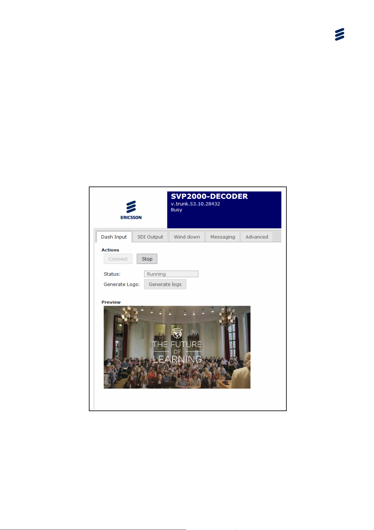
3.8 Starting the SVP 2000 Decoder
When the Decoder is configured, start it by clicking Connect under the Dash input
or RTP input menus. Click Stop to stop the decode process.
Note: To make changes to the unit’s configuration it must be in a stopped state.
If the incoming source is missing or incorrectly configured and the Decoder is
started, then the unit will be in a Waiting state until this is resolved.
If the incoming source is present and correctly configured and the Decoder is
started, then the unit will be in a Running state. The Preview will display sample
images of the incoming video.
This page will also indicate if there is an issue within the SVP 2000 and can
generate the unit’s logs.
Getting Started
Figure
EN/LZT 790 0046/1 R1A
3.6 Decoder DASH Input Page
3-11
Page 46
Getting Started
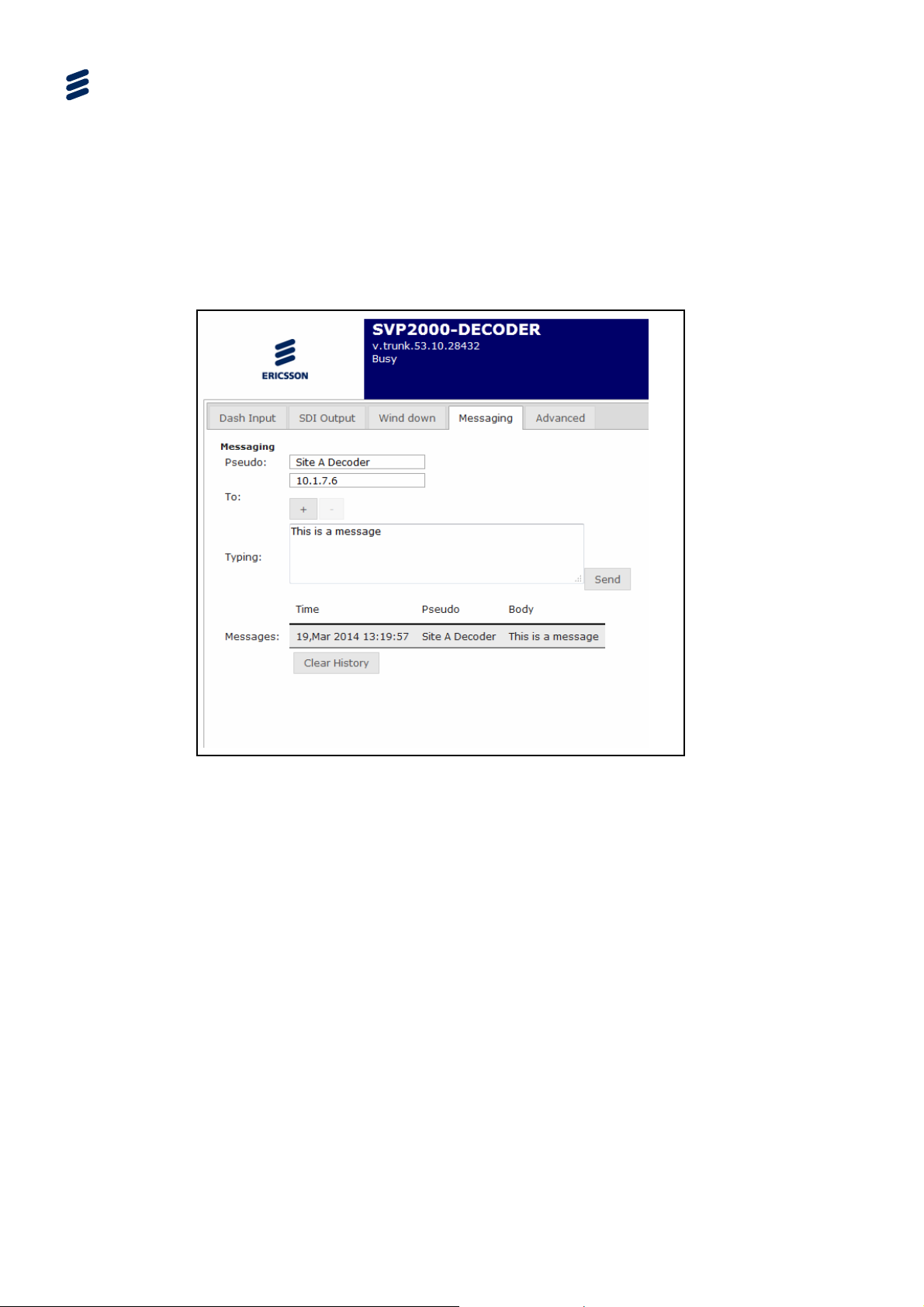
3.9 Messaging
The SVP 2000 can send instant messages between devices via the Messaging tab.
The Pseudo is a name for the unit. The address for the destination device(s) is
below this.
The message content is input into the Typing box, and the messages log is shown
below this.
Figure
3.7 Messaging Page
3.10 Upgrading the SVP 2000 Unit
There are no hardware options available for the SVP 2000.
It is possible to modify the licensed features of the SVP 2000 after purchase by
entry of an appropriate key. New license keys are available for purchase from
Ericsson. Each key is unique to a specific unit and therefore the serial number must
be provided for each unit that requires an update. In return, a key will be provided.
The change in licensed keys will be available after the unit has been rebooted.
For further details, see Chapter 6.
3-12
EN/LZT 790 0046/1 R1A
Page 47

4 Encoder Web-based GUI Control
Chapter 4
Contents
4.1 What This Chapter Describes............................................................... 4-5
4.2 Encoder Tabbed Pages........................................................................ 4-5
4.2.1 Overview............................................................................................... 4-5
4.2.2 Encoder GUI Context-sensitive Navigation Buttons ............................. 4-7
4.3 Header Status Display.......................................................................... 4-7
4.4 First Tier (Live Operation) Pages .........................................................4-8
4.4.1 Publishing Tabbed Page ......................................................................4-8
4.4.1.1 Publishing - SDI Input........................................................................... 4-8
4.4.1.2 Publishing – TS Multiplexing ................................................................4-9
4.4.1.3 Publishing – RTP Output ....................................................................4-11
4.4.2 Input Tabbed Page .............................................................................4-13
4.4.2.1 SDI Input Tabbed Page ......................................................................4-13
4.4.2.2 SDI Input Tabbed Page Buttons......................................................... 4-14
4.4.3 TS Input Tabbed Page .......................................................................4-14
4.4.4 Archiving Page ...................................................................................4-16
4.4.5 Wind Down Tabbed Page................................................................... 4-17
4.4.5.1 Wind Down (SDI Input)....................................................................... 4-17
4.4.5.2 Wind Down Page Buttons................................................................... 4-17
4.4.6 Messaging Tabbed Page.................................................................... 4-18
4.4.6.1 Messaging Page................................................................................. 4-18
4.4.6.2 Messaging Page Buttons.................................................................... 4-18
4.5 Advanced Tabbed Pages ................................................................... 4-19
4.5.1 Overview............................................................................................. 4-19
4.5.2 Device Status Tabbed Page............................................................... 4-19
4.5.2.1 Device Status Page ............................................................................4-19
4.5.2.2 Device Status Page Button................................................................. 4-20
4.5.3 Network Tabbed Page........................................................................ 4-21
4.5.3.1 Network Page .....................................................................................4-21
4.5.3.2 Network Page Button.......................................................................... 4-23
4.5.4 SDI Input Details Tabbed Page ..........................................................4-23
4.5.4.1 SDI Input Page ................................................................................... 4-23
4.5.4.2 SDI Input Page Button........................................................................ 4-25
4.5.5 TS Input Details Tabbed Page ...........................................................4-26
4.5.6 Video Profiles .....................................................................................4-29
4.5.6.1 Video Encoding Common Parameters ...............................................4-30
4.5.6.2 Advanced Video Encoding Parameters.............................................. 4-31
4.5.6.3 Slate Insertion..................................................................................... 4-32
EN/LZT 790 0046/1 R1A
4-1
Page 48

Encoder Web-based GUI Control
4.5.6.4 Common Video Preprocessing........................................................... 4-32
4.5.6.5 Video Encoding Parameters............................................................... 4-33
4.5.6.6 Advanced Encoding Parameters........................................................ 4-35
4.5.6.7 De-interlace Input............................................................................... 4-36
4.5.6.8 Advanced Video Preprocessing ......................................................... 4-37
4.5.6.9 Logo Insertion .................................................................................... 4-37
4.5.6.10 Logo Position ..................................................................................... 4-38
4.5.6.11 Logo Resize ....................................................................................... 4-38
4.5.7 Audio Profiles Tabbed Page............................................................... 4-39
4.5.7.1 Audio Profiles Page............................................................................ 4-39
4.5.7.2 Audio Profiles Items ........................................................................... 4-39
4.5.7.3 Audio Encoding Items ........................................................................ 4-40
4.5.7.4 Audio Codec Items............................................................................. 4-41
4.5.7.5 Audio Mode Items .............................................................................. 4-42
4.5.7.6 Audio Resampling Items .................................................................... 4-42
4.5.7.7 Audio Profiles Tabbed Page Buttons ................................................. 4-43
4.5.7.8 Audio Adjust Items ............................................................................. 4-43
4.5.8 Subtitling Tab ..................................................................................... 4-44
4.5.9 Export/Import Tabbed Page ............................................................... 4-44
4.5.9.1 Export/Import Page ............................................................................ 4-44
4.5.9.2 Export/Import Tabbed Page Button.................................................... 4-44
4.5.10 Alarm/Event Tabbed Page ................................................................. 4-45
4.5.10.1 Alarm/Event Page .............................................................................. 4-45
4.5.10.2 Alarm/Event Tabbed Page Button...................................................... 4-46
4.5.11 License Tabbed Page ........................................................................ 4-46
4.5.11.1 License Tabbed Page – Information Display...................................... 4-46
4.5.11.2 License Tabbed Page – Switch Mode................................................ 4-47
4.5.11.3 License Tabbed Page – How to Change the Encoder Mode ............. 4-47
List of Figures
Figure 4.1
Map of Encoder Tabbed Pages [MPEG-DASH Output Example] ........ 4-5
Figure 4.2 Map of Encoder Tabbed Pages [RTP-TS Output Example]................. 4-6
Figure 4.3 Encoder Header ................................................................................... 4-7
Figure 4.4 Publishing Tab (SDI Input) ................................................................... 4-8
Figure 4.5 Publishing Tabbed Page – TS Multiplexing.......................................... 4-9
Figure 4.6 Publishing Tabbed Page – RTP Output ............................................. 4-11
Figure 4.7 SDI Input Tabbed Page...................................................................... 4-13
Figure 4.8 TS Input Tabbed Page ....................................................................... 4-15
Figure 4.9 Archiving Tab ..................................................................................... 4-16
Figure 4.10 Wind Down Tabbed Page .................................................................. 4-17
Figure 4.11 Messaging Tabbed Page ................................................................... 4-18
Figure 4.12 Device Status Tabbed Page............................................................... 4-19
Figure 4.13 Network Tabbed Page........................................................................ 4-21
Figure 4.14 SDI Input Details Tabbed Page.......................................................... 4-24
Figure 4.15 TS Input Details Tabbed Page ........................................................... 4-26
Figure 4.16 Video Profiles Tabbed Page............................................................... 4-29
Figure 4.17 Advanced Video Encoding Parameters.............................................. 4-31
Figure 4.18 Advanced Encoding Dialog ................................................................ 4-35
Figure 4.19 Audio Profile Tabbed Page ................................................................ 4-39
Figure 4.20 Subtitling Page .................................................................................. 4-44
4-2
EN/LZT 790 0046/1 R1A
Page 49

Encoder Web-based GUI Control
Figure 4.21 Export/Import Tabbed Page ............................................................... 4-44
Figure 4.22 Alarm/Event Tabbed Page ................................................................. 4-45
Figure 4.23 License Tabbed Page......................................................................... 4-46
Figure 4.24 License Page – Switch Encoder Mode ...............................................4-47
List of Tables
Table 4.1
Device Statuses ...................................................................................4-7
Table 4.2 Publishing Tabbed Page(SDI Input) Item Descriptions ........................4-9
Table 4.3 Publishing Tabbed Page – TS Multiplexing Item Descriptions........... 4-10
Table 4.4 Publishing Tabbed Page – RTP Output Item Descriptions ................4-12
Table 4.5 SDI Input Tabbed Page Item Descriptions .........................................4-13
Table 4.6 Messaging Tabbed Page Item Descriptions....................................... 4-18
Table 4.7 Device Status Tabbed Page Item Descriptions.................................. 4-20
Table 4.8 Network Tabbed Page Item Descriptions........................................... 4-22
Table 4.9 SDI Input Tabbed Page Item Descriptions .........................................4-24
Table 4.10 Input Video Standards ........................................................................4-25
Table 4.11 Timecode............................................................................................ 4-25
Table 4.12 TS Input Details Tabbed Page Item Descriptions............................... 4-27
Table 4.13 Video Profiles Tabbed Page Item Description.................................... 4-30
Table 4.14 Codec Item Descriptions ....................................................................4-30
Table 4.15 Advanced Video Encoding Parameters Item Descriptions ................. 4-31
Table 4.16 Slate Insertion..................................................................................... 4-32
Table 4.17 Common Video Preprocessing........................................................... 4-32
Table 4.18 Codec Profile Item Descriptions ......................................................... 4-33
Table 4.19 Output Size Items ............................................................................... 4-34
Table 4.20 Frame Rate Items............................................................................... 4-35
Table 4.21 Advanced Encoding Item Descriptions............................................... 4-36
Table 4.22 Advanced Video Preprocessing Item Descriptions............................. 4-37
Table 4.23 Logo Insertion Parameters .................................................................4-37
Table 4.24 Logo Graphics File Support................................................................ 4-38
Table 4.25 Logo Position Dropdown Items........................................................... 4-38
Table 4.26 Logo Resize Dropdown Items ............................................................4-38
Table 4.27 Audio Profiles Tabbed Page Item Description.................................... 4-39
Table 4.28 Audio Encoding Item Description .......................................................4-40
Table 4.29 Codec Item Description ...................................................................... 4-41
Table 4.30 Allowable Bit Rates for MPEG-1 Layer II (kbps)................................. 4-41
Table 4.31 Allowed Encoding Bit Rates for AAC (kbps)....................................... 4-42
Table 4.32 Audio Mode Item Description .............................................................4-42
Table 4.33 Audio Resampling Options ................................................................. 4-43
Table 4.34 Audio Adjust Item Description ............................................................4-43
Table 4.35 Alarm/Event Log Tabbed Page Item Descriptions.............................. 4-46
EN/LZT 790 0046/1 R1A
4-3
Page 50

Encoder Web-based GUI Control
BLANK
4-4
EN/LZT 790 0046/1 R1A
Page 51
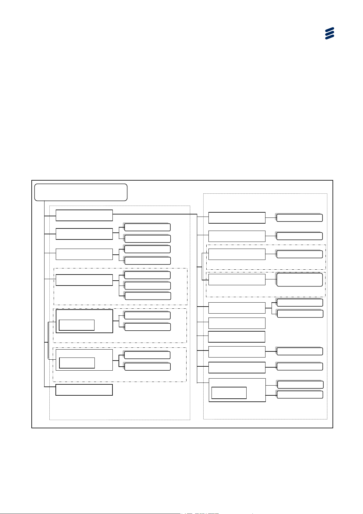
p
g
y
4.1 What This Chapter Describes
This chapter describes the functionality of the SVP 2000 Encoder GUI.
4.2 Encoder Tabbed Pages
4.2.1 Overview
The following figures show the site map for the Encoder Web-based GUI. They are
arranged in two tiers. Those under the Advanced Tab (second tier) are required for
setting up the unit, whereas those on the top (first tier) are concerned with live
operation.
Encoder Web-based GUI Control
SVP 2000 Encoder
SVP2000/SWO/EN/BAS
Advanced
Messaging
Wind down
Archiving
SVP2000/SWO/EN/FI-ST
Video Input
Confidence Display
SDI To MPEG-DASH mode
Video Input
Confidence Display
MPEG-TS To
SDI Input
TS Input
MPEG-DASH mode
Publishing
First Tier (Live Operation) Pages
Send
Clear Histor
Reboot
Shut Down
Start ding/Stop Recor
Send Selected URL
Avail. for Download
Connect/Stop
Generate Logs
Connect/Stop
Generate Logs
Device Status
Network
SDI Input Details
Browse
Apply changes
Apply changes
SDI To MPEG-DASH mode
TS Input Details
Switch to Primary/
Secondary
MPEG-TS To MPEG-DASH mode
Video Profiles
Export Video Config
Im
ort Video Confi
Audio Profiles
Subtitling
Export/Import
Alarm/Event Log
License
Change SVP 2000
Browse
Generate Events
Switch
Browse
Second Tier (Set Up) Pages
Figure
EN/LZT 790 0046/1 R1A
4.1 Map of Encoder Tabbed Pages [MPEG-DASH Output Example]
4-5
Page 52

p
g
y
ode
Encoder Web-based GUI Control
SVP 2000 Encoder
SVP2000/SWO/EN/BAS
Advanced
Messaging
Wind down
Archiving
SVP2000/SWO/EN/FI-ST
SDI Input
Video Input
Confidence Display
SDI To RTP-TS mode
Confidence Display
MPEG-TS To RTP-TS mode
TS Input
Video Input
Send
Clear Histor
Reboot
Shut Down
Start ding/Stop Recor
Send Selected URL
Avail. for Download
Connect/Stop
Generate Logs
Connect/Stop
Generate Logs
Device Status
Network
SDI Input Details
SDI To RTP-TS mode
TS Input Details
Switch to Primary/
MPEG-TS To RTP-TS mode
Video Profiles
Export Video Config
Im
Audio Profiles
Subtitling
Export/Import
Browse
Apply changes
Apply changes
Secondary
ort Video Confi
Browse
Figure
Publishing
TS Multiplexing
RTP Output
First Tier (Live Operation) Pages
Generate SDP file
Alarm/Event Log
License
Change SVP 2000
M
Second Tier (Set Up) Pages
4.2 Map of Encoder Tabbed Pages [RTP-TS Output Example]
Caution!
The SVP 2000 unit needs to be in a stopped state before any settings can be
changed.
Note: Refer to Section 4.5.11 License Tabbed Page for details of license
requirements for Encoder modes etc.
Generate Events
Switch
Browse
4-6
EN/LZT 790 0046/1 R1A
Page 53

Encoder Web-based GUI Control
4.2.2 Encoder GUI Context-sensitive Navigation Buttons
Advanced
Back
Messaging
Publishing
Examples of context-sensitive navigation buttons are available at
the bottom of first tier pages.
Their functio
n depends on which page is currently selected.
4.3 Header Status Display
The device status is shown in the web page header.
Table
Figure
4.1 Device Statuses
4.3 Encoder Header
Item Description Notes
Unknown
Unregistered Device license is invalid
Busy Device is busy At least one of its channels is not stopped
Stopped Device is stopped All its channels are stopped
Monitoring Device is a spare device
Sparing Device is a spare device
Searching Device is not accessible
Device co
contacted
uld not be
It is not running, but currently monitoring the devices it is
configured to spare
It is actually running, replacing one of the device it is
configured to spare
EN/LZT 790 0046/1 R1A
4-7
Page 54
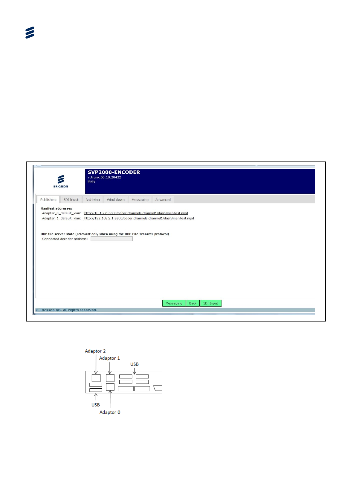
Encoder Web-based GUI Control
4.4 First Tier (Live Operation) Pages
4.4.1 Publishing Tabbed Page
4.4.1.1 Publishing - SDI Input
This page gives the URL of the stream Manifest file (DASH Media Presentation
Description).
Note: The Archiving Tab is only displayed if the SVP2000/SWO/EN/FI-ST license
is enabled.
Figure
4-8
4.4 Publishing Tab (SDI Input)
EN/LZT 790 0046/1 R1A
Page 55

Table 4.2 Publishing Tabbed Page(SDI Input) Item Descriptions
Item Description Notes
Encoder Web-based GUI Control
Adapter_0_default_vlan Manifest Addresses
Adapter_1_default_vlan
UDP file server state
Connected Decoder IP
address
4.4.1.2 Publishing – TS Multiplexing
The URL of the stream manifest.
For MPEG DASH it should
be served with the
‘application/dash+xml’ MIME type. If you connect an
Allegro DASH output, the ‘manifest_templated.mpd’ URL
shall be used.
Figure
4.5 Publishing Tabbed Page – TS Multiplexing
EN/LZT 790 0046/1 R1A
4-9
Page 56

Encoder Web-based GUI Control
Table 4.3 Publishing Tabbed Page – TS Multiplexing Item Descriptions
Group Item Description Notes
Multiplexing
IDs
Several audio per PES
packets
TS CBR (add null
packet)
PES packet may contain
several audio access unit
Fill the MPEG-2 TS stream
with Null Packets so as to
achieve the total transport bit
rate specified.
PSI/Chunk period
Repetition rate in ms between
each PAT/PMT.
Scheduling mode Possible values are:
- DVB/ATSC Compliance
- Ordered by timestamps
TSID
Transport Stream ID affected
to the generated output SPTS
Program number
Program Number affected to
the only program in the
generated output SPTS
PMT PID
Program Map table PID
affected to the only program
in the generated output SPTS
Video PID
PID affected to the output
video stream in the generated
output SPT
DVB-Teletext PID #1
PID affected to the output
Teletext stream #n in the
DVB-Teletext PID #2
generated output SPTS
In SVP 2000 output it
corresponds to chunk period.
Ordered by timestamps: key
frame alignment has to be
activated for each video
encoding profile.
This setting is unavailable if
no Teletext #n input has been
selected
SCTE-35 PID
PID affected to the output
SCTE-35 stream in the
generated output SPTS
DVB-Subtitle PID #1
PID affected to the output
DVB-Subtitle stream #n in the
DVB-Subtitle PID #2
KLV PID #1
generated output SPTS.
PID affected to the output
KLV stream #n in the
KLV PID #2
generated output SPTS
Audio Stream
Audio PID
Audio
PID affected to the output
audio stream corresponding
to the selected audio profile in
the generated output SPTS
4-10
EN/LZT 790 0046/1 R1A
This setting is unavailable if
no SCTE-35 input has been
selected
This setting is unavailable if
no DVB-Subtitle #n stream
input has been selected
This setting is unavailable if
no KLV #n stream input has
been selected
This setting is unavailable if
no audio corresponding to
that profile input has been
selected
Page 57

Encoder Web-based GUI Control
Group Item Description Notes
Language descriptor
Full language name for which
the corresponding ISO-639.2
language code will be
associated in the audio
output.
4.4.1.3 Publishing – RTP Output
The SVP 2000 delivers its encoded or transcoded output in distinct RTP/RTCP
streams, carried over UDP/IP (Ethernet interface), to one unicast or multicast
address. For each channel to be delivered, the user chooses one unicast or
multicast address “A” and one UDP port “P”. “P” must be even (for instance, 5004).
The device then delivers its output to:
RTP for video stream to address A, port P. (5004)
RTCP for video stream to address A, port P+1. (5005)
RTP for audio stream to address A, port P+2. (5006)
Choices are:
- Disabled
- Arabic
- Bulgarian
- ...
- Custom (ISO-639.2 code
must be filled with a three
letters code)
Figure
RTCP for audio stream to address A, port P+3. (5007)
The SVP 2000 is able to deliver several audio/video streams to the same Ethernet
interface. If so, they must be delivered to different IP addresses or ports each. The
device in RTP Ethernet output could be optionally specified as an ATSC M/H output.
4.6 Publishing Tabbed Page – RTP Output
EN/LZT 790 0046/1 R1A
4-11
Page 58

Encoder Web-based GUI Control
Table
4.4 Publishing Tabbed Page – RTP Output Item Descriptions
Group Item Description Notes
Ethernet interface
IP address
Port
Interface
Send SAP
announces
Use default session
name
FEC FEC mode
Ethernet plu
g to which to deliver
the output audio/video stream.
This stream is an MPEG-2 SPTS
containing the encoded or
transcoded audio/video stream.
IP address to which to deliver the
output audio/video stream.
First UDP port to which to deliver
the output audio/video stream.
This must be an even port. This
port and the 3 subsequent ports
will be used respectively for video
RTP, video RTCP, audio RTP,
and audio RTCP streams.
Enable SAP announces
The default session name will be
used in SDP file
Mode used to calculate Forward
Error Correction for audio/video
stream
Choices are:
- Ethernet Plug #1
- Ethernet Plug #2
A usual setting is to set video
network on plug #
This can be a unicast IP address or
a multicast IP address
For instance, if UDP Port is set to
5004, the following ports will be
used, all on the same destination IP
address:
- 5004 for video RTP
- 5005 for video RTCP
- 5006 for audio RTP
- 5007 for audio RTCP
Choices are:
None
Basic, FEC on row packets only
Level A, FEC on column packets
only
Level B, FEC on both column and
row packets
4-12
Caution!
DVB-Teletext, DVB-Subtitle, KLV, SCTE-35 can only be delivered to RTP-TS output
mode; and a Decoder can make use of them only if it itself delivers to TS mode.
EN/LZT 790 0046/1 R1A
Page 59

4.4.2 Input Tabbed Page
4.4.2.1 SDI Input Tabbed Page
This page enables high-level Encoder control. It allows the device to be stopped and
started. It shows the unit’s current status. It also has a video confidence display
which shows the video entering the SVP 2000.
Encoder Web-based GUI Control
Figure
Table
4.7 SDI Input Tabbed Page
4.5 SDI Input Tabbed Page Item Descriptions
Item Description Notes
Status
Unknown Device could not be contacted
Unregistered Device license is invalid
Busy Device is busy. At least one of its channels is not stopped
Stopped Device is stopped. All its channels are stopped
Monitoring
Device is a spare device. It is not running, but currently
monitoring the devices it is configured to spare
Sparing
Device is a spare device. It is actually running, replacing
one of the device it is configured to spare
Searching Device is not accessible
EN/LZT 790 0046/1 R1A
4-13
Page 60

Encoder Web-based GUI Control
4.4.2.2 SDI Input Tabbed Page Buttons
Stop
: stop the currently selected audio/video encoding or transcoding
channel. This sends an SNMP SET command to the device. The
device then generates one or more SNMP traps, showing that is
stopping or has stopped. This buttons also applies to spare
devices, to stop them from sparing. Available only if channel is
running.
Connect
: start the currently selected audio/video encoding or transcoding
channel. This sends an SNMP SET command to the device. The
device then generates one or more SNMP traps, showing that is
starting or has started, or the reason why it cannot start.
Available only when no change is made or all changes have
been applied.
Generate Logs
: logs are continuously generated and logged within the unit.
Pressing of this tab creates a temporary link of the current log
file for a user to download. This log file can then be sent to
Ericsson for analysis.
4.4.3 TS Input Tabbed Page
This page enables high-level Encoder control. It allows the device to be stopped and
started. It shows the unit’s current status. It also has a video confidence display
which shows the video entering the SVP 2000.
Note: This page is only displayed only when the Encoder is in SDI to RTP-TS or
MPEG-TS to MPEG-DASH mode.
Items on the page are the same as for SDI Input (see Table
4.5)
4-14
EN/LZT 790 0046/1 R1A
Page 61
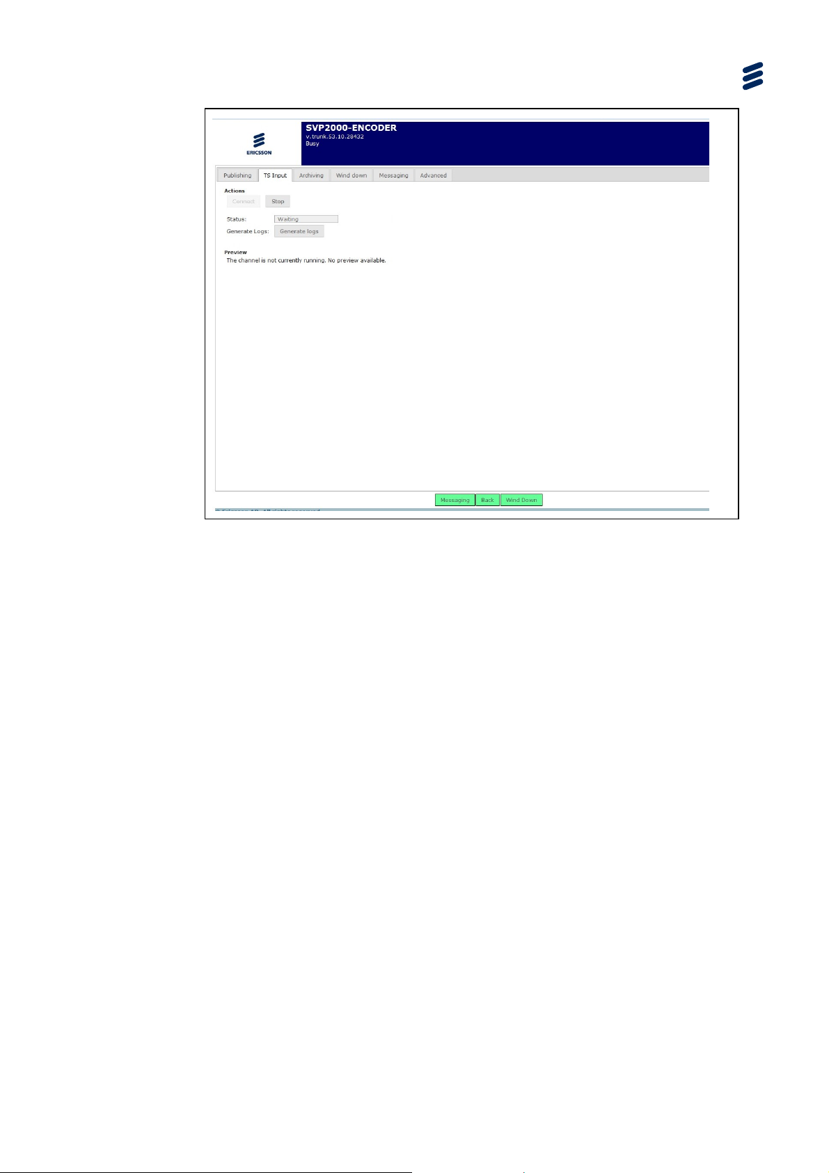
Encoder Web-based GUI Control
Figure
4.8 TS Input Tabbed Page
EN/LZT 790 0046/1 R1A
4-15
Page 62
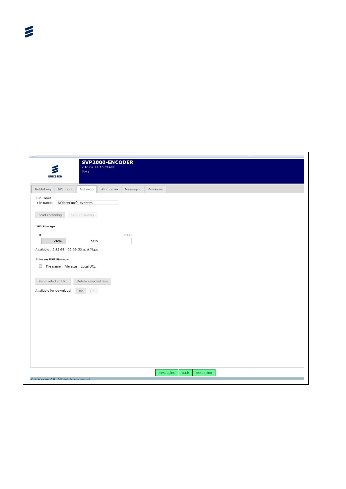
Encoder Web-based GUI Control
4.4.4 Archiving Page
Notes: The Archiving Tab is only displayed if the SVP2000/SWO/EN/FI-ST license
is enabled.
The USB memory stick must be NTFS formatted.
If no USB memory stick is connected or it is not correctly formatted the
following message is displayed on the page: “No USB storage connected.
Please connect an USB storage.”
Figure
4-16
4.9 Archiving Tab
EN/LZT 790 0046/1 R1A
Page 63
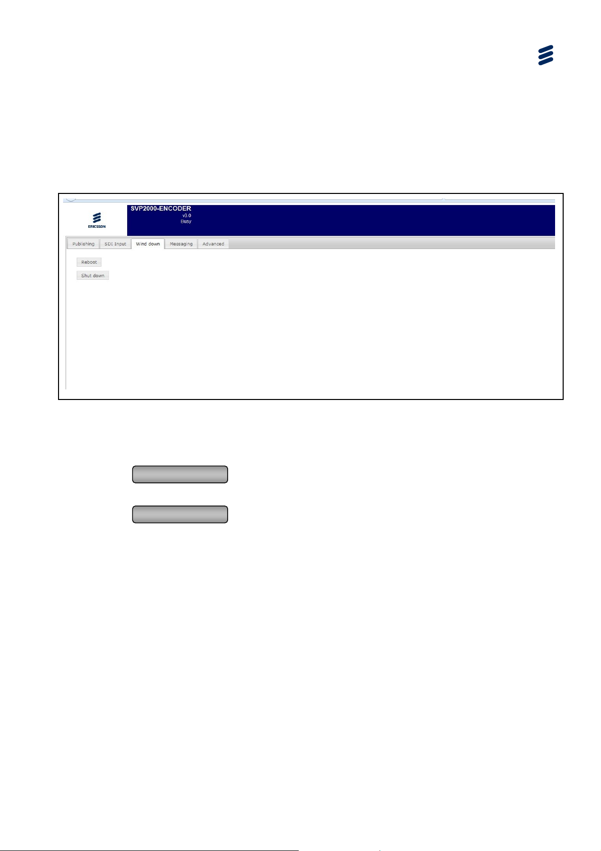
4.4.5 Wind Down Tabbed Page
This page enables high-level control at a device level. It allows the device to be shut
down. It also enables a reboot (when the device is stopped).
4.4.5.1 Wind Down (SDI Input)
Encoder Web-based GUI Control
Figure
4.10 Wind Down Tabbed Page
4.4.5.2 Wind Down Page Buttons
Reboot
: reboot the currently selected device. A confirmation is
requested. Available only when the device is stopped.
Shut down
: shut down (power off) the currently selected device. A
confirmation is requested. Available only when the device is
stopped (see SDI Input/TS Input Tabbed Page).
EN/LZT 790 0046/1 R1A
4-17
Page 64

Encoder Web-based GUI Control
4.4.6 Messaging Tabbed Page
4.4.6.1 Messaging Page
The SVP 2000 can send instant messages between devices via the Messaging tab.
Pseudo is a name for the unit. The address for the destination device(s) is below
this.
The message content is input into the Typing box, and the messages log is shown
below this.
Figure
Table
4.11 Messaging Tabbed Page
4.6 Messaging Tabbed Page Item Descriptions
Item Description Notes
Pseudo Name of unit
To IP Address of the Decoder
Typing Message field
4.4.6.2 Messaging Page Buttons
Send
Clear History
: sends the message to the Decoder
: clears the
message history
4-18
EN/LZT 790 0046/1 R1A
Page 65
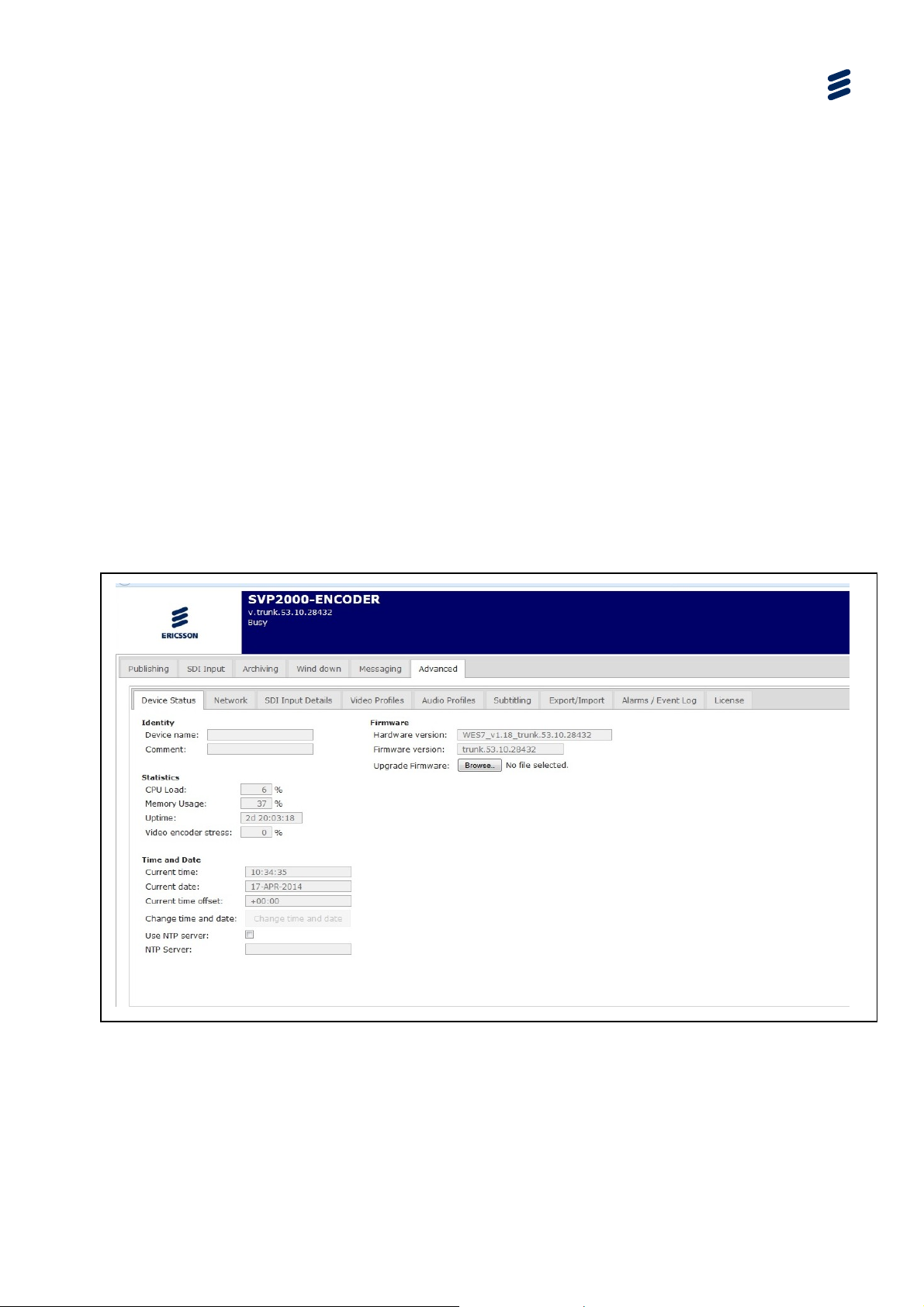
4.5 Advanced Tabbed Pages
4.5.1 Overview
The pages accessed via the Advanced Tab are used to set up the unit prior to live
operation.
4.5.2 Device Status Tabbed Page
4.5.2.1 Device Status Page
The Device Status page is a sub-tab under the Advanced Tab.
This page displays CPU Usage and buffer status which is part of the DASH MDP.
The current versions of the Firmware and Hardware are displayed on this page.
Also, a Windows Browser can be opened from this page to find the location of the
Zip file containing any new Firmware Update for the SVP 2000.
Encoder Web-based GUI Control
Figure
EN/LZT 790 0046/1 R1A
4.12 Device Status Tabbed Page
4-19
Page 66

Encoder Web-based GUI Control
Table 4.7 Device Status Tabbed Page Item Descriptions
Group Item Description Notes
Device Name Identity
Statistics
Time and
Date
Comment
May be used for storing a comment
about this device
Examples are: location, current use,
owner, etc.
CPU Load
Memory Usage
Uptime
Video Encoder
Stress
Current time Local time of the device It is of the form HH:MM:SS
Current date Date of the device It is of the form DD-MMM-YYYY
Current time offset Time offset of the device
This is the difference between local
time and UTC time. It is of the form
+/-HH:MM.
Current Time Offset is the only
parameter which can be set when the
Use NTP server check box is selected
Change time and
date
Use NTP server
Allows a new time offset, date and
time to be set on the device
if this check box is selected, the
Same form as current time offset,
date and time
device tries to run a NTP client to
use the NTP clock.
NTP server
IP address of the NTP server used
to retrieve NTP clock
Firmware
Hardware version Device hardware version
Firmware version Device firmware version
Upgrade Firmware
4.5.2.2 Device Status Page Button
Browse
: opens a window which allows the file containing the firmware update to be
located.
4-20
EN/LZT 790 0046/1 R1A
Page 67

4.5.3 Network Tabbed Page
4.5.3.1 Network Page
The Network page is a sub-tab under the Advanced Tab.
Encoder Web-based GUI Control
Figure
4.13 Network Tabbed Page
EN/LZT 790 0046/1 R1A
4-21
Page 68

Encoder Web-based GUI Control
Table 4.8 Network Tabbed Page Item Descriptions
Group Item Description Notes
Adaptor 0
Default VLAN
VPN Setup
Use DHCP
Select the Use DHCP check box to
enable this function.
The Dynamic Host Configuration
Protocol (DHCP) is a networking
protocol used on an IP network to
allocate IP addresses to computers.
This en
configuration of a computer without a
network administrator.
An IP address is assigned to a
computer for a set interval (from a
range of assigned IP addresses
stored in a database), after which, the
computer must renew the IP address
or acquire a new one.
IP address
Netmask
Gateway
Preferred DNS Domain Name Space
RFC 1035, RFC 1123, and RFC 2181
define the rules for forming domain
names
Alternate DNS
Use VPN
connection
Selecting the Use VPN connection
check box enables the VPN
connection
ables the IP address
Server
address
Login
Password
Status
Local address
Address of the VPN server
Login that the device will use to
connect to the VPN
Password that the device will use to
connect to the VPN
Describes the current status of the
VPN connection
When the Status is "Connected",
"Local Address" describes the
current local address of the device
in the private network
This can also be a host name if the
DNS is configured on the device. The
server must be reachable from one of
the Ethernet network
Select the Show characters check box
to show the password as it is being
typed
It is assigned by the VPN server and
cannot be changed from the device
4-22
EN/LZT 790 0046/1 R1A
Page 69

Encoder Web-based GUI Control
Group Item Description Notes
Adaptor 1
Default VLAN
Use DHCP
Netmask
Gateway
Preferred DNS Domain Name Space
Alternate DNS
Select the Use DHCP check box to
enable this function
4.5.3.2 Network Page Button
Apply Changes
: click Apply Changes to save any new settings.
The Dynamic Host Configuration
Protocol (DHCP) enables the IP
address configuration of a computer
without a network administrator.
An IP address is assigned to a
computer for a set interval (from a
range of assigned IP addresses
stored in a database), after which, the
computer must renew the IP address
or acquire a new one.
RFC 1035, RFC 1123, and RFC 2181
define the rules for forming domain
names
4.5.4 SDI Input Details Tabbed Page
4.5.4.1 SDI Input Page
Notes: Video input size is automatically selected from the SDI video input.
The device is able to process uncompressed SDI video input(s).
Number of inputs: 2x SMPTE 259M.
Supports uncompressed 8-bit/10-bit digital video capture.
For each channel to be processed, the user chooses one SDI input among the two
available, and one of the stereo audio channels among eight.
EN/LZT 790 0046/1 R1A
4-23
Page 70

Encoder Web-based GUI Control
Figure
4.14 SDI Input Details Tabbed Page
Table
4.9 SDI Input Tabbed Page Item Descriptions
Group Item Description Notes
Interface
SDI interface
Aspect Ratio
Use teletext
SDI connector from which to
receive the input audio/video
stream. Choices are:
• RX0
• RX1
The Aspect Ratio of input video
has to be selected by the user.
Whe
n using RTP mode in TS
output, incoming teletext is
passed thorough
This video stream is an SD-SDI stream
with embedded audio.
Choices are:
• 4:3
• 16:9
• Pass-Through
If "Pass-Through" is selected, the input
aspect ratio is detected in the WSS or
AFD embedded SDI.
4-24
EN/LZT 790 0046/1 R1A
Page 71

Encoder Web-based GUI Control
Group Item Description Notes
RXO
Video Standard
Timecode standard
Choose between several SDI
formats.
Type of timecodes of each plug of
the SDI board.
4.5.4.2 SDI Input Page Button
Apply Changes
: click Apply Changes to save any new settings.
4.10 Input Video Standards
Table
Input Video Standard
720x576i 25fps PAL
720x576i 25fps
NTSC 720x480i 29.97fps
The following formats are available:
• PAL 720x576i 25fps
• PAL 720x576i 25fps
• NTSC 720x480i 29.97fps
• HD 1920x1080p 25fps
• HD 1920x1080p 30fps
• HD 1920x1080i 50fps
• HD 1920x1080i 60fps
• HD 1280x720p 50fps
• HD 1280x720p 60fps
This is not necessarily the same
standard used for RX0 and RX1
HD
1920x1080p 25fps
1920x1080p 30fps
1920x1080i 50fps
1920x1080i 60fps
T
4.11 Timecode
able
1280x720p 50fps
1280x720p 60fps
Timecode Options
NONE Disabled
VITC Vertical Interleaved Time Code
EN/LZT 790 0046/1 R1A
4-25
Page 72

Encoder Web-based GUI Control
4.5.5 TS Input Details Tabbed Page
The TS Input Details page is a sub-tab under the Advanced Tab.
Note: In Figure
4.15 the Encoder is shown performing a PID scan. At the end of
the scan, a set of PIDs will be displayed as follows:
Figure
4-26
4.15 TS Input Details Tabbed Page
EN/LZT 790 0046/1 R1A
Page 73

Encoder Web-based GUI Control
Table 4.12 TS Input Details Tabbed Page Item Descriptions
Group Item Description Notes
Settings
Primary Source
RTP FEC
Switching mode
Detection threshold
Ethernet interface
Enable TS-RTP input with FEC
(availabl
e only in “Single
Source” mode)
Switching mode between
primary and secondary source
The delay after which the input
is considered failing, in
milliseconds
Ethernet plu
g from which to
receive the input audio/video
stream. This stream is an
MPEG-2 SD SPTS or MPTS
Expected FE
C ports on “UDP
Port”+2 and “UDP Port”+4
Choices are:
Single Source : Only primary
source is used.
Manual : Manual source
switching with “Switch To
Primary/Secondary” push
buttons
Automatic with manual
fallback to primary
Auto with auto fallback to
primary
A usual setting is to set video
netwo
rk on Adaptor 1.
Secondary source
IP address
IP address on which to receive
the input audio/video stream
UDP port
UDP port on which to receive
the input audio/video stream
Source specific
multicast
Switch to primary
Ethernet interface
Ethernet plug from which to
receive the input audio/video
stream. This stream is an
MPEG-2 SD SPTS or MPTS.
IP address
IP address on which to receive
the input audio/video stream.
UDP port
UDP port on which to receive
the input audio/video stream
Source specific
multicast
Switch to secondary
This must be either a multicast
address or “0.0.0.0” (unicast
input)
A usual setting is to set video
network on Adaptor 1.
This must be either a multicast
address or “0.0.0.0” (unicast
input)
EN/LZT 790 0046/1 R1A
4-27
Page 74

Encoder Web-based GUI Control
Group Item Description Notes
PID selection
Mode
Use video PID
(Video) PID
Audio PID selection
This parameter offers different
methods for choosing the PIDs
from the input demultiplexer
The following modes are
available:
Manual: the user enters each
PID.
Stream: the system
automatically selects the first
video PID and audio PIDs
from the service having the
lowest service number.
Service: the user enters a
service number, and the
system automatically selects
the video and audio PIDs in
this service
Use video stream for
transcoding
PID identifying an audio stream
to transcode from the input
multiplex. It can be set to 0 not
to process the audio
DVB-Teletext
DVB-Subtitle
KLV
SCTE-35
Pid scan
PID identifying a Teletext stream
to transfer from the input
multiplex.
PID identifying a DVB-Subtitle
stream to transfer from the input
multiplex. It can be set to 0 not
to process the DVB-Subtitle
PID identifying a KLV stream to
transfer from the input multiplex.
It can be set to 0 not to process
the KLV.
PID identifying the SCTE-35 to
transfer from the input multiplex
The Scan button is a facility
designed to discover the PIDs
from the input Transport Stream.
It can be set to 0 not to
process the Teletext. When
output mode is “Smooth
Streaming”, Teletext will be
converted to TTML text track
in the smooth streaming
presentation.
Asynchronous KLV stream are
converted to synchronous.
The PID scanner use the
given IP address, UDP port
and Ethernet interface and
report back graphically what
was detected
4-28
EN/LZT 790 0046/1 R1A
Page 75
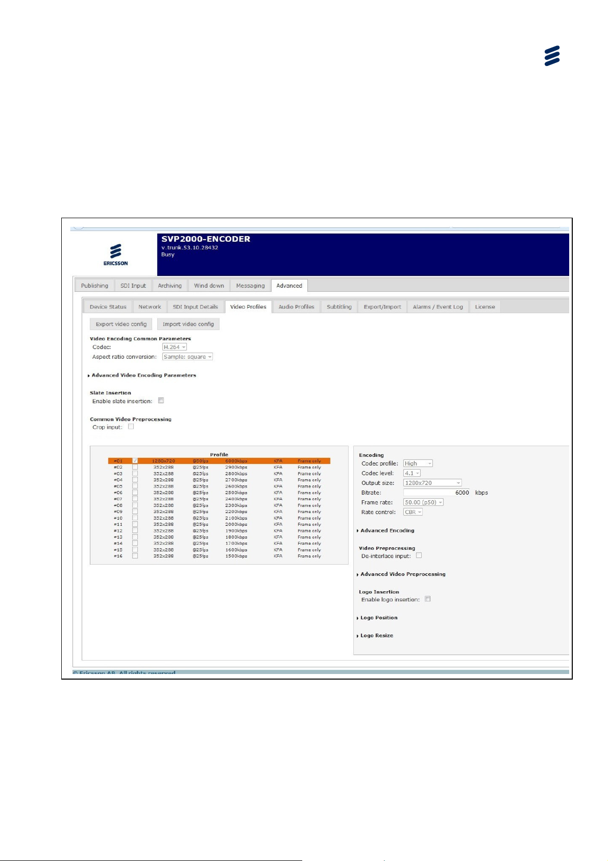
4.5.6 Video Profiles
The Video Profiles page is a sub-tab under the Advanced Tab.
This page sets the video encoding parameters for the Encoder output and allows up
to five video profiles to be selected from the list.
Encoder Web-based GUI Control
Note: KFA is the abbreviation for Key Frames Alignment – see Table
4.21
Figure
EN/LZT 790 0046/1 R1A
4.16 Video Profiles Tabbed Page
4-29
Page 76

Encoder Web-based GUI Control
4.5.6.1 Video Encoding Common Parameters
Notes: The settings under the Video Encoding Common Parameters Group are
common to all the video profiles.
Choices may be limited by the license granted to your device
4.13 Video Profiles Tabbed Page Item Description
Table
Item Description Notes
Codec
Codec with which to encode or
transcode the input video stream
See Table 4.14
Aspect Ratio
Conversation
Pass-through
Sample: Square
Display: 4:3
Display: 16:9
4.14 Codec Item Descriptions
able
T
Item
MPEG-2
MPEG-4 SP
H.263
H.264
The output aspect ratio can be
changed by adding black bands
Description
ISO/IEC 13818: Widely used
for the transmission of digital
television signals
MPEG-4 Simple Profile used
in situation
use of low bit rate and low
resolution
ITU-T H.263 for video
transport stream using RTP
ITU-T H.264 (MPEG-4 AVC)
covers a wide range of digital
compressed video from low bit
rate internet streaming to
HDTV
s which require the
Notes
4-30
WM Video 8 WM Video 8:
WM Video 9 WM Video 9:
VC-1
EN/LZT 790 0046/1 R1A
SMPTE 421M – based on WM
Video 9
Page 77

4.5.6.2 Advanced Video Encoding Parameters
Encoder Web-based GUI Control
Figure
Table
Item Options
Video format PAL
Chromaticity BT.709-5
Aspect ratio
signaling
4.17 Advanced Video Encoding Parameters
4.15 Advanced Video Encoding Parameters Item Descriptions
Notes
Video format value set in H.264 stream "video
NTSC
SECAM
MAC
Unspecified
BT.470-6 M
BT.470-6 B,G
SMPTE 170M (1999)
SMPTE 240M (1999)
Pass-through
Sample: Square
Display: 4:3
usability information" section. This does not
affect the encoding process, and has no link
with the video input format or encoding size.
This may affect the display process on the
decoder, if the decoder uses this information.
Chromaticity value set in H.264 stream “video
usability information” section. This does not
affect the encoding process, and has no link
with the video input format or encoding size.
This may affect the display process on the
decoder, if the decoder uses this information.
The output aspect ratio signaled in the stream.
”Pass-through” signaled the aspect ratio
chosen in “Aspect Ratio Conversion”.
Display: 16:9
GOP size
Random-Access-Point (RAP) period. A RAP is
necessary for a video decoder to start
decoding (zap time). If GOP Size is set to 1000
ms, this means that a decoder may have to
wait up to 1 s after switch on (0.5 s on
average) before being able to start displaying.
Increasing the GOP Size increases video
visual quality and increases zap time.
Bottom field
first
Number of
Encode the video in
Bottom Field First.
encoding
passes
EN/LZT 790 0046/1 R1A
4-31
Page 78

Encoder Web-based GUI Control
4.5.6.3 Slate Insertion
Note: Choices may be limited by the license granted to your device
4.16 Slate Insertion
Table
Item Description Notes
Enable Slate
Insertion
Enables/Disables Slate Insertion.
4.5.6.4 Common Video Preprocessing
4.17 Common Video Preprocessing
Table
Item Description Notes
Crop input
Apply cropping on the input
image,
When Slate insertion is enabled, the
late picture hides the video output
and the audio is muted. The slate
insertion is common to all the video
profiles. This parameter can be set
dynamically while the device is
running.
Raw (case of SDI inputs), or decoded
(case of IP inputs).
4-32
EN/LZT 790 0046/1 R1A
Page 79

4.5.6.5 Video Encoding Parameters
Encoder Web-based GUI Control
Table
4.18 Codec Profile Item Descriptions
Video
Codec Profile Codec Level Notes
Codec
MPEG-2
MPEG-4 SP Simple 0
H.263 0 45 ITU-T H.263 for video transport stream using RTP
H.264 Baseline 1
Main 1b
High 1.1
1.2
1.3
2
2.1
2.2
3
Main Main
High
1
2
ISO/IEC 13818: Widely used for the transmission of
digital television signals
MPEG-4 Sim
require the use of low bit rate and low resolution
3
ITU-T H.264 (MPEG-4 AVC) covers a wide range of
digital compressed video from low bit rate internet
streaming to HDTV
Baseline profile: Primarily for low cost applications
that require additional data loss robustness
3.1
3.2
4
Main: Used for standard-definition TV content
High: The primary profile for broadcast applications,
particularly for high definition TV
ple Profile used in situations which
4.1
4.2
5
5.1
WM Video 8 WM Video 8:
WM Video 9 WM Video 9:
VC-1 SMPTE 421M – based on WM Video 9
EN/LZT 790 0046/1 R1A
4-33
Page 80

Encoder Web-based GUI Control
Table 4.19 Output Size Items
Standard Description
1920x1080 High Definition
1440x1080
1280x720
720x576 Standard Definition
720x480 Standard Definition
544x576
544x480
480x576
480x480
480x360
480x320
400x224
384x224
352x576
352x480
352x288 Common Intermediate Format
352x240
320x240 Quarter Video Graphics Array
320x176
192x192
176x144 Quarter Common Intermediate Format
144x80
128x96 Sub- Quarter Common Intermediate Format
Custom...
4-34
EN/LZT 790 0046/1 R1A
Page 81

Encoder Web-based GUI Control
Table 4.20 Frame Rate Items
Rate Description
0.50
1.00
2.00
3.00
3.74
5.00
7.49
7.50
8.00
10.00
12.50
14.98
24.00
25.00
29.97
"29.97" stands for the exact "30000/1001"
frequency, "3.74", "7.49", 14.98" stand for
submultiples of this frequency
30.00
Custom…
4.5.6.6 Advanced Encoding Parameters
Click the Advanced Encoding drop-down arrow to reveal the dialog box elements.
Figure
EN/LZT 790 0046/1 R1A
4.18 Advanced Encoding Dialog
4-35
Page 82

Encoder Web-based GUI Control
Table 4.21 Advanced Encoding Item Descriptions
Item Description Notes
Quality level Three quality levels are available
Frame only
Only frames are encoded,
mandatory when Codec is not
H264. When it is, it can be limited
by the profile the level and the
frame rate change
Slide show
Enables slide show mode
mode
Key frames
alignment
Enable the IDR alignment
between bit rates
From left to right, this setting
increases quality but decreases
scalability
• Must be activated when the
contents is to be delivered to a PC,
Mac, tablet, smartphone, or any
player not supporting field encoding.
• Must be deactivated when the
content is to be delivered to a player
supporting field encoding, such as a
set-top box connected to a TV set, if
appropriate.
• If in doubt, if your player supports
field encoding, or only frame-based
encoding.
This function is:
• available with RTP output in multi
rate mode
• available with Flash output in multi
rate mode; it shall be enabled if
smooth bit rate switching is required.
Otherwise, it can be disabled for an
optimum video quality.
• unavailable with MPEG-2 TS output
in multi rate mode
• unavailable with WMF output in
multi rate mode.
• available with IPhone output
• automatically enabled with
Silverlight - Smooth Streaming output
and MPEG DASH
Enable frame
interpolation
No B frames
Disables encoder ability to
encode B frames.
Disable
Select to disable video encoding
hardware
encoding
4.5.6.7 De-interlace Input
Select the De-interlace input check
4-36
EN/LZT 790 0046/1 R1A
Mandatory in Baseline profile.
box to de-interlace the video before encoding.
Page 83

4.5.6.8 Advanced Video Preprocessing
4.22 Advanced Video Preprocessing Item Descriptions
T
able
Encoder Web-based GUI Control
Item Description
Auto color
enhancement
Brightness
Contrast
Gamma
Performs an automatic setting of
the levels.
Brightness makes the video
darker or brighter.
Increasing the contrast can
improve the output.
Gamma compensates for the
differences between different
display technologies and devices,
such as when encoding for
handheld devices and terminals,
targeting Mac/PC, etc.
Notes
The value can be set from -100 to
100. It affects all pixels linearly,
unlike the Contrast filter which makes
dark pixels become darker and bright
pixels brighter
Video encoded from PAL or NTSC
can sometimes look a bit grey, or
milky, when digitized. Contrast
adjustment makes the dark pixels
darker and the lighter pixels lighter.
Be careful not to increase the
contrast too much as the lighter
pixels have a tendency to become a
“white blur”. By lowering the contrast,
the image will become more flat or
greyish.
Gamma is probably the most
common filter to use and might be
the most important correction to do.
Gamma is a non-linear filter. It only
affects the midrange tones but leaves
the darkest and lightest parts
unchanged. This is useful for
darkening or lightening a picture
without the risk of distorting the white
areas. Positive numbers (1 to 100)
make the image lighter. Negative
numbers (-1 to -100) make the image
darker.
Saturation
Saturation changes the intensity
of the colour.
Moving the slider to the right
(increasing the values), intensifies
the colours, and vice versa. The
value can be set from -100 to 100.
4.5.6.9 Logo Insertion
Table
4.23 Logo Insertion Parameters
Group Item Description Notes
Logo
insertion
EN/LZT 790 0046/1 R1A
Logo Insertion
Preview logo
Enables/Disables Logo
Insertion
Display the logo picture
present on device
Only available if the Enable Logo
Insertion check box is selected
4-37
Page 84

Encoder Web-based GUI Control
Table 4.24 Logo Graphics File Support
Supported File
Notes
Formats
BMP, GIF, JPEG,
EXIF, PNG and TIFF
The process takes into account the alpha channel present in the
picture. Alpha compositing is the process of combining an image with
the video stream to create the appearance of partial transparency
4.5.6.10 Logo Position
Table
4.25 Logo Position Dropdown Items
Group Item Description Notes
Logo Position
Mode
Defines the reference
position of the logo
Horizontal Gap Defines the Horizontal Gap
Vertical Gap
Defines the Vertical Gap
Options are:
• Top Left
• Top Right
• Center
• Bottom Left
• Bottom Right
The Center automatically positions the
logo
In percent of the stream width between
the horizontal reference position (Left or
Right) and the nearest side of the logo
In percent of the stream height between
the vertical reference position (Top or
Bottom) and the nearest side of the logo
4.5.6.11 Logo Resize
Table
4.26 Logo Resize Dropdown Items
Group Item Description Notes
Logo Resize
Mode
There are four ways to
resize the logo. Options
"No" resize - the original logo size is
kept and directly applied to the stream
are:
• No (resize)
• Width Based
• Height Based
• Free" resize
Width Based - he logo width is resized
according to a percent of the width of
the stream. This method keeps the
original ratio of the logo
Height Based - the logo height is
resized according to a percent of the
height of the stream. This method keeps
the original ratio of the logo
Free resize - the user can set the width
and the height size in percent of the
size of
the stream
Width Width of the logo In percent of the stream width
Height Height of the logo In percent of the stream height
4-38
EN/LZT 790 0046/1 R1A
Page 85

If the size of the logo is out of screen, the logo is cropped automatically.
4.5.7 Audio Profiles Tabbed Page
4.5.7.1 Audio Profiles Page
The Audio Profiles page is a sub-tab under the Advanced Tab. It allows audio
profiles to be configured and assigned to a check box for ease of use.
Encoder Web-based GUI Control
Caution!
Figure
4.19 Audio Profile Tabbed Page
4.5.7.2 Audio Profiles Items
4.27 Audio Profiles Tabbed Page Item Description
T
able
Item Description Notes
Profile
Audio Encoding See
Audio Adjust See Table 4.34 for details
EN/LZT 790 0046/1 R1A
Select the 'Audio Profile' to
configure. Displays the
parameters corresponding to the
chosen profile
It can be set from 1 to 8 limited by
the license granted to your device.
Table 4.31 and Table 4.29
4-39
Page 86

Encoder Web-based GUI Control
4.5.7.3 Audio Encoding Items
4.28 Audio Encoding Item Description
Table
Item Description Notes
Codec
Select the Codec from the drop
See Table 4.29 for options
down list
Mode
Select the Mode from the drop
See Table 4.32 for options
down list
Resample
Select the Audio input resampling
See Table 4.33 for options
from the drop down list
Bitrate
Select the audio encoding bit rate
from the drop down list
See Table 4.30 to
Table 4.31 for details
4-40
EN/LZT 790 0046/1 R1A
Page 87

4.5.7.4 Audio Codec Items
Encoder Web-based GUI Control
Table
4.29 Codec Item Description
Codec
Options Notes
Output
Pass-through MPEG-2 TS
RTP
ATSC M/H HE-AAC v2 (implicit SBR, mp4-generic)
Adobe Flash
AAC-LC: "ADTS", "LATM/LOAS"
HE-AAC v1: "implicit SBR, ADTS", "implicit SBR,
LATM/LOAS", "explicit SBR, LATM/LOAS"
HE-AAC v2: "implicit SBR, ADTS", "implicit SBR,
LATM/LOAS", "explicit SBR, LATM/LOAS"
MPEG1-L
ayer II See Table 4.30 for allowable bit rates
AAC-LC: "mp4-generic", "MP4A-LATM"
HE-AAC v1: "implicit SBR, mp4-generic", "implicit
SBR, MP4A-LATM", "explicit SBR, MP4A-LATM"
HE-AAC v2: "implicit SBR, mp4-generic", "implicit
SBR, MP4A-LATM", "explicit SBR, MP4A-LATM"
AAC-LC
HE-AAC v1: "implicit SBR", "explicit SBR"
See
Table 4.31for allowable bit rates
Silverlight Smooth
Streaming
MPEG DASH
IPhone
HE-AAC v2: "implicit SBR+PS"
See
AAC-LC (ADTS)
Table 4.31for allowable bit rates
HE-AAC v1: "implicit SBR, ADTS"
HE-AAC v2: "implicit SBR+PS, ADTS"
AAC-LC (ADTS)
HE-AAC v1: "implicit SBR, ADTS"
HE-AAC v2: "implicit SBR+PS, ADTS"
AAC-LC (ADTS)
HE-AAC v1 (explicit SBR, ADTS)
HE-AAC v2 (implicit SBR+PS, ADTS)
The followin
T
able
g tables list all allowed bit rates, for every output codec.
4.30 Allowable Bit Rates for MPEG-1 Layer II (kbps)
Sampling Rate (Hz) MPEG-1 Layer II Mono / MPEG-1 Layer II Stereo
32000, 44100, 48000 64, 96, 112, 128, 160, 192, 224, 256, 320, 384
EN/LZT 790 0046/1 R1A
4-41
Page 88

Encoder Web-based GUI Control
Table 4.31 Allowed Encoding Bit Rates for AAC (kbps)
Sampling
Rate (Hz)
AAC-LC
Mono
AAC-LC
Stereo
HE-AAC
v1 Mono
HE-AAC
v1 Stereo
HE-AAC v2
Parametric
Stereo
11025 8,10, 12 16, 20 N/A N/A N/A
12000
16000
22050 32, 36 24, 28 8, 10 N/A 8,10
24000 32, 36 24, 28 8, 10 N/A 8,10
32000
44100
8,10, 12 16, 20 N/A N/A N/A
8, 10, 12, 16,
20, 24, 28
32, 36, 40, 48,
56, 64, 72, 80,
88, 96, 112,
128, 160
56, 64, 72, 80,
88, 96, 112,
128, 160
16, 20, 24, 28,
32, 36
40, 48, 56, 64,
72, 80, 88, 96,
112, 128, 160,
192, 224, 256,
320
96, 112, 128,
160, 192, 224,
256, 320
N/A N/A N/A
12, 16, 20, 24,
28, 32, 36, 40,
48, 56
20, 24, 28, 32,
36, 40, 48, 56
16, 20, 24, 28,
32, 36, 40, 48,
56, 64, 72, 80,
88, 96, 112, 128
16, 20, 24, 28
32, 36, 40, 48,
56, 64, 72, 80,
88, 96, 112, 128
12, 16, 20, 24,
28, 32, 36, 40,
48, 56
,
20, 24, 28, 32,
36, 40, 48, 56
48000
56, 64, 72, 80,
88, 96, 112,
128, 160, 192,
224, 256
96, 112, 128,
160, 192, 224,
256, 320, 384,
448, 512
4.5.7.5 Audio Mode Items
4.32 Audio Mode Item Description
Table
Option Description Notes
Stereo
Mono (L)
Mono (R)
Mono (L+R)
5.1
Available values for audio input resampling (see Table 4.33) depends on the Audio
Mode and the Audio Codec.
4.5.7.6 Audio Resampling Items
20, 24, 28, 32,
36, 40, 48, 56
16, 20, 24, 28,
32, 36, 40, 48,
56, 64, 72, 80,
88, 96, 112, 128
This setting is unavailable is
no audio #n input has been
selected.
20, 24, 28, 32
36, 40, 48, 56
,
4-42
This sett
ing is unavailable if no audio #n input has been selected.
Note: Choices may be limited by the license granted to your device.
EN/LZT 790 0046/1 R1A
Page 89

Encoder Web-based GUI Control
Table 4.33 Audio Resampling Options
Option Description Notes
none
11025Hz
12000Hz
16000Hz
Dep
22050Hz
24000Hz
32000Hz
44100Hz
48000Hz
ends on the Audio
Mode and the AudioCodec
Note: This only affects this audio elementary stream, and does not account for
possible subsequent encapsulation processes.
4.5.7.7 Audio Profiles Tabbed Page Buttons
Export audio config
: This button
opens the Save Audio window which allows audio
settings to be saved.
Import audio config
: This button opens the Load Audio window which enables an
audio file to be located and uploaded.
4.5.7.8 Audio Adjust Items
If audio codec is
Passthrough, this setting is
unavailable: bit rate cannot
be chosen as audio is
passed through with no
further processing; it is only
re-synchronized, but not reencoded nor transcoded.
4.34 Audio Adjust Item Description
able
T
Item Description Notes
Level
AGC
Select the audio input level from the
drop down list
Select AGC to activate the Automatic
Gain Control
0,300 (infinity,+4.8dB]
EN/LZT 790 0046/1 R1A
4-43
Page 90
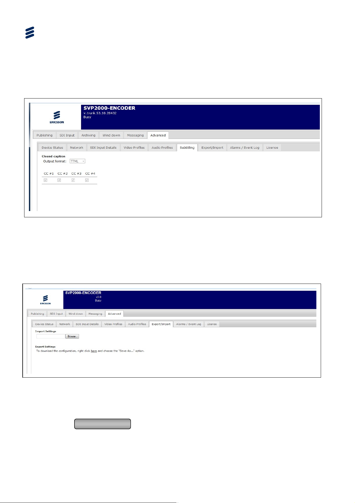
Encoder Web-based GUI Control
4.5.8 Subtitling Tab
The Subtitling page is a sub-tab under the Advanced Tab. Strictly, this page is
associated with Closed Captions.
Figure
4.20 Subtitling Page
4.5.9 Export/Import Tabbed Page
4.5.9.1 Export/Import Page
The Export/Import page is a sub-tab under the Advanced Tab.
Figure 4.21 Export/Import Tabbed Page
4.5.9.2 Export/Import Tabbed Page Button
Browse
: allows the setting file to be located or created.
4-44
EN/LZT 790 0046/1 R1A
Page 91

4.5.10 Alarm/Event Tabbed Page
4.5.10.1 Alarm/Event Page
The Alarm/Event page is a sub-tab under the Advanced Tab.
Encoder Web-based GUI Control
Figure
EN/LZT 790 0046/1 R1A
4.22 Alarm/Event Tabbed Page
4-45
Page 92
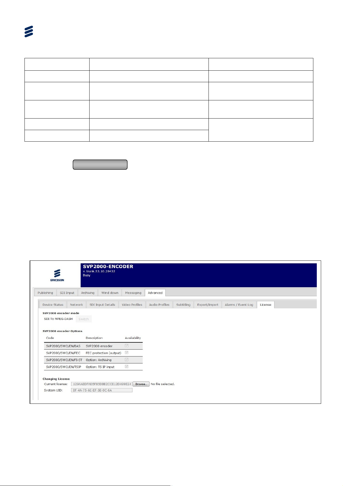
Encoder Web-based GUI Control
Table 4.35 Alarm/Event Log Tabbed Page Item Descriptions
Item Description Notes
Number List number
Date/Time
Date and time at when the Event was
received
Source
Encoding/transcoding channel which
generated the event.
Kind Event kind
Message Event message
4.5.10.2 Alarm/Event Tabbed Page Button
Generate Events
: creates a link pointing to a file that can be downloaded
containing the alarms/events that are displayed on the GUI.
4.5.11 License Tabbed Page
4.5.11.1 License Tabbed Page – Information Display
The License page is a sub-tab under the Advanced Tab. The page shows the
current licenses. It also allows the Encoder mode to be switched.
Note: Some modes are only available if certain licenses are purchased.
See Annex C for a complete
description
4-46
Figure
EN/LZT 790 0046/1 R1A
4.23 License Tabbed Page
Page 93
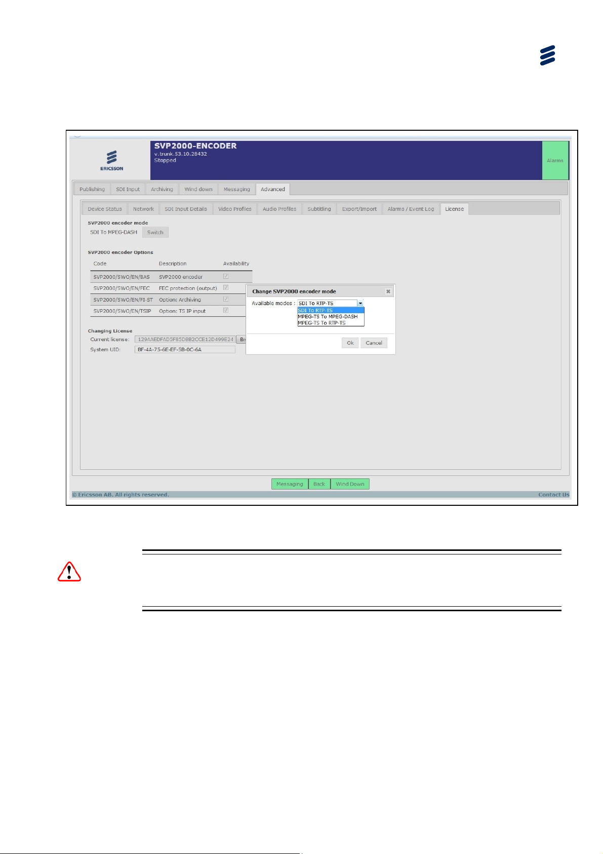
Available licenses are described in Chapter 6, Software Licensing and Upgrades.
4.5.11.2 License Tabbed Page – Switch Mode
Encoder Web-based GUI Control
Figure
4.24 License Page – Switch Encoder Mode
Caution!
The Encoder must be stopped for the Switch button to be available.
4.5.11.3 License Tabbed Page – How to Change the Encoder Mode
In the License sub-tab under the Advanced tab:
Stop the Encoder (via the SDI Input or TS Input page depending on current
mode)
click Switch
select the new mode, among:
EN/LZT 790 0046/1 R1A
4-47
Page 94

Encoder Web-based GUI Control
Note: The currently operating mode does not appear in the list.
Click Connect to set the Encoder in to the selected mode.
- SDI To MPEG-DASH
- SDI To RTP-TS
- MPEG-TS To MPEG-DASH
- MPEG-TS To RTP-TS
4-48
EN/LZT 790 0046/1 R1A
Page 95

5 Decoder Web-based GUI Control
Chapter 5
Contents
5.1 What this Chapter Describes................................................................ 5-5
5.2 Decoder Tabbed Pages........................................................................ 5-5
5.3 Header Status Display.......................................................................... 5-6
5.4 First Tier (Live Operation) Pages .........................................................5-8
5.4.1 DASH Input Tabbed Page ....................................................................5-8
5.4.1.1 DASH Input (SDI Output) .....................................................................5-8
5.4.1.2 DASH Input (TS Output)....................................................................... 5-9
5.4.1.3 DASH Input Page Buttons ....................................................................5-9
5.4.2 Output Tab Pages ..............................................................................5-10
5.4.2.1 SDI Output Tabbed Page ................................................................... 5-10
5.4.2.2 TS Output Tabbed Page..................................................................... 5-11
5.4.3 Wind Down Tabbed Page................................................................... 5-12
5.4.3.1 Wind Down (SDI Output) .................................................................... 5-12
5.4.3.2 Wind Down Page Buttons................................................................... 5-12
5.4.4 Messaging Tabbed Page.................................................................... 5-13
5.4.4.1 Messaging Page................................................................................. 5-13
5.4.4.2 Messaging Page Buttons.................................................................... 5-13
5.5 Advanced Tabbed Pages ................................................................... 5-14
5.5.1 Overview............................................................................................. 5-14
5.5.2 Device Status Tabbed Page............................................................... 5-14
5.5.2.1 Device Status Page ............................................................................5-14
5.5.2.2 Device Status Page Buttons............................................................... 5-15
5.5.3 Network Tabbed Page........................................................................ 5-16
5.5.3.1 Network Page .....................................................................................5-16
5.5.3.2 Network Page Button.......................................................................... 5-18
5.5.4 DASH Input Details Tabbed Page ......................................................5-18
5.5.4.1 DASH Input Details Page ................................................................... 5-18
5.5.4.2 DASH Input Details (UDP Selected) – FEC Mode.............................. 5-20
5.5.5 SDI Output Details Tabbed Page ....................................................... 5-21
5.5.5.1 SDI Output Page ................................................................................5-21
5.5.5.2 Slate Insertion..................................................................................... 5-22
5.5.5.3 Slate Related Buttons......................................................................... 5-22
5.5.5.4 Logo Insertion..................................................................................... 5-22
5.5.5.5 Logo Insertion Related Buttons .......................................................... 5-24
5.5.6 TS Input Details Tabbed Page ...........................................................5-24
5.5.6.1 TS Input Details Page......................................................................... 5-24
5.5.7 TS Multiplexing Tabbed Page ............................................................5-24
EN/LZT 790 0046/1 R1A
5-1
Page 96

Decoder Web-based GUI Control
5.5.8 Video Profiles Tabbed Page............................................................... 5-27
5.5.8.1 Video Encoding Common Parameters............................................... 5-27
5.5.8.2 Advanced Video Encoding Parameters.............................................. 5-28
5.5.8.3 Slate Insertion .................................................................................... 5-29
5.5.8.4 Common Video Preprocessing........................................................... 5-30
5.5.8.5 Video Encoding Parameters............................................................... 5-30
5.5.8.6 Advanced Encoding Parameters........................................................ 5-32
5.5.8.7 De-interlace Input............................................................................... 5-33
5.5.8.8 Advanced Video Preprocessing ......................................................... 5-34
5.5.8.9 Logo Insertion .................................................................................... 5-34
5.5.8.10 Logo Position ..................................................................................... 5-35
5.5.8.11 Logo Resize ....................................................................................... 5-35
5.5.9 Audio Profiles Tabbed Page............................................................... 5-36
5.5.9.1 Audio Profiles Items ........................................................................... 5-37
5.5.9.2 Audio Encoding Items ........................................................................ 5-37
5.5.9.3 Audio Codec Items............................................................................. 5-38
5.5.9.4 Audio Resampling Items .................................................................... 5-40
5.5.9.5 Audio Profiles Tabbed Page Buttons ................................................. 5-40
5.5.9.6 Audio Adjust Items ............................................................................. 5-40
5.5.10 Subtitling Tabbed Page...................................................................... 5-41
5.5.11 Export/Import Tabbed Page ............................................................... 5-41
5.5.11.1 Export/Import Page ............................................................................ 5-41
5.5.11.2 Export/Import Tabbed Page Button.................................................... 5-42
5.5.12 Alarm/Event Log Tabbed Page .......................................................... 5-42
5.5.12.1 Alarm/Event Log Page ....................................................................... 5-42
5.5.12.2 Alarm/Event Tabbed Page Button...................................................... 5-43
5.5.13 License Tabbed Page ........................................................................ 5-43
5.5.13.1 License Tabbed Page – Information Display...................................... 5-43
5.5.13.2 License Tabbed Page – Switch Mode................................................ 5-44
5.5.13.3 License Tabbed Page – How to Change the Decoder Mode ............. 5-44
List of Figures
Figure 5.1
Map of Decoder Tabbed Pages [MPEG-DASH Input Example) .......... 5-5
Figure 5.2 Map of Decoder Tabbed Pages [RTP-TS Input to SDI Output Example)5-6
Figure 5.3 Decoder Header................................................................................... 5-6
Figure 5.4 DASH Input Tab (SDI Output).............................................................. 5-8
Figure 5.5 DASH Input Tab (TS Output) ............................................................... 5-9
Figure 5.6 SDI Output Tab .................................................................................. 5-10
Figure 5.7 TS Output Tab.................................................................................... 5-11
Figure 5.8 Wind Down Tab (SDI Output)............................................................. 5-12
Figure 5.9 Messaging Tab (SDI Output).............................................................. 5-13
Figure 5.10 Device Status Tabbed Page............................................................... 5-14
Figure 5.11 Network Tabbed Page........................................................................ 5-16
Figure 5.12 DASH Input Tabbed Page.................................................................. 5-19
Figure 5.13 DASH Input Details (UDP Selected) – FEC Mode ............................. 5-20
Figure 5.14 SDI Output Details Tabbed Page ....................................................... 5-21
Figure 5.15 TS Input Details Tabbed Page ........................................................... 5-24
Figure 5.16 TS Multiplexing Tabbed Page ............................................................ 5-25
Figure 5.17 Video Profiles Page............................................................................ 5-27
Figure 5.18 Advanced Video Encoding Parameters.............................................. 5-28
5-2
EN/LZT 790 0046/1 R1A
Page 97

Decoder Web-based GUI Control
Figure 5.19 Advanced Encoding Dialog ................................................................ 5-32
Figure 5.20 Audio Profiles Page ............................................................................ 5-36
Figure 5.21 Subtitling Page ................................................................................... 5-41
Figure 5.22 Export/Import Tabbed Page (TS Output)........................................... 5-41
Figure 5.23 Alarm/Event Tabbed Page ................................................................. 5-42
Figure 5.24 License Tabbed Page......................................................................... 5-43
List of Tables
Table 5.1
Device Statuses ................................................................................. 5-7
Table 5.2 DASH Input Tab Item Descriptions ......................................................5-8
Table 5.3 SDI Output Video Format Options ..................................................... 5-10
Table 5.4 Messaging Tabbed Page Item Descriptions....................................... 5-13
Table 5.5 Device Status Tabbed Page Item Descriptions.................................. 5-15
Table 5.6 Network Tabbed Page Item Descriptions........................................... 5-17
Table 5.7 DASH Input Tabbed Page Items ........................................................ 5-19
Table 5.8 FEC Mode Item Parameters (Transport Protocol: UDP) .................... 5-21
Table 5.9 Slate Insertion Common Parameters .................................................5-22
Table 5.10 Logo Insertion Parameters .................................................................5-22
Table 5.11 Logo Graphics File Support................................................................ 5-22
Table 5.12 Logo Position Dropdown Items........................................................... 5-23
Table 5.13 Logo Resize Dropdown Items ............................................................5-23
Table 5.14 TS Multiplexing Tabbed Page Items Descriptions.............................. 5-25
Table 5.15 Video Profiles Tabbed Page Item Description.................................... 5-28
Table 5.16 Codec Item Descriptions ....................................................................5-28
Table 5.17 Advanced Video Encoding Parameters Item Descriptions ................. 5-29
Table 5.18 Slate Insertion..................................................................................... 5-29
Table 5.19 Common Video Preprocessing........................................................... 5-30
Table 5.20 Codec Profile Item Descriptions ......................................................... 5-30
Table 5.21 Output Size Items ............................................................................... 5-31
Table 5.22 Frame Rate Items............................................................................... 5-32
Table 5.23 Advanced Encoding Item Descriptions............................................... 5-33
Table 5.24 Advanced Video Preprocessing Item Descriptions............................. 5-34
Table 5.25 Logo Insertion Parameters .................................................................5-34
Table 5.26 Logo Graphics File Support................................................................ 5-35
Table 5.27 Logo Position Dropdown Items........................................................... 5-35
Table 5.28 Logo Resize Dropdown Items ............................................................5-35
Table 5.29 Audio Profiles Tabbed Page Item Description.................................... 5-37
Table 5.30 Audio Encoding Item Description .......................................................5-37
Table 5.31 Codec Item Description ...................................................................... 5-38
Table 5.32 Allowable Bit Rates for MPEG-1 Layer II (kbps)................................. 5-38
Table 5.33 Allowed Encoding Bit Rates for AAC (kbps)....................................... 5-39
Table 5.34 Audio Mode Item Description .............................................................5-39
Table 5.35 Audio Resampling Options ................................................................. 5-40
Table 5.36 Audio Adjust Item Description ............................................................5-40
Table 5.37 Export/Import Tabbed Page Item Descriptions................................... 5-42
Table 5.38 Alarm/Event Log Tabbed Page Item Descriptions.............................. 5-43
EN/LZT 790 0046/1 R1A
5-3
Page 98

Decoder Web-based GUI Control
BLANK
5-4
EN/LZT 790 0046/1 R1A
Page 99
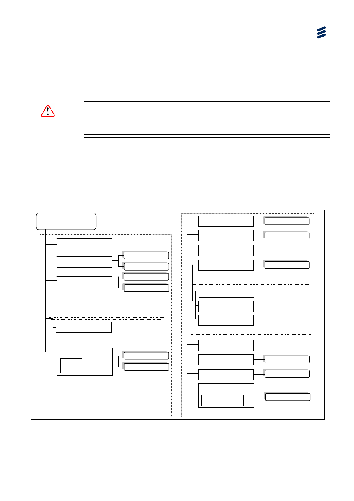
y
5.1 What this Chapter Describes
This chapter describes the functionality of the SVP 2000 Decoder GUI.
Caution!
The SVP 2000 unit needs to be stopped state before any settings can be changed.
5.2 Decoder Tabbed Pages
The following figures show the site map for the Decoder Web-based GUI. They are
arranged in two tiers. Those under the Advanced Tab (second tier) are required for
setting up the unit, whereas those on the top (first tier) are concerned with live
operation.
Decoder Web-based GUI Control
SVP 2000 Decoder
Advanced
Messaging
Wind down
SDI Output
MPEG-DAS
H To SDI mode
TS Output
MPEG-DASH To MPEG-TS mode
DASH Input
Video Input
Confidence
Display
Send
Clear Histor
Reboot
Shut Down
Connect/Stop
Generate Logs
Device Status
Network
DASH Input Details
SDI Output Details
MPEG-DASH To SDI mode
TS Multiplexing
Video Profiles
Audio Profiles
MPEG-DAS
H To TS mode
Subtitling
Export/Import
Alarm/Event Log
Browse
Apply changes
Apply changes
Browse
Generate Events
First Tier (Live Operation) Pages
Change SVP 2000
Mode
Second Tier (Set Up) Pages
Figure
EN/LZT 790 0046/1 R1A
5.1 Map of Decoder Tabbed Pages [MPEG-DASH Input Example)
Switch
5-5
Page 100

y
Decoder Web-based GUI Control
SVP 2000 Decoder
Advanced
Messaging
Wind down
SDI Output
TS Input
Video Input
Confidence
Display
Send
Clear Histor
Reboot
Shut Down
Connect/Stop
Generate Logs
Device Status
Network
TS Input Details
SDI Output Details
Subtitling
Export/Import
Alarm/Event Log
Change
SVP 2000
Mode
Browse
Apply changes
Apply changes
Browse
Generate Events
Switch
First Tier (Live Operation) Pages
Figure
5.2 Map of Decoder Tabbed Pages [RTP-TS Input to SDI Output Example)
Note: Refer to Section
5.5.13 License Tabbed Page for details of license
requirements for Decoder modes etc.
5.3 Header Status Display
The device status is shown in the web page header.
Figure
5.3 Decoder Header
Second Tier (Set Up) Pages
5-6
EN/LZT 790 0046/1 R1A
 Loading...