

Ericsson SE W760 Diagram

Working Instruction, Mechanical
Working Instruction, Mechanical
Applicable for W760
CONTENTS
Introduction ............................................................................................................3
1
1.1 View of W760...............................................................................................3
1.2 Tools and Equipment ...................................................................................3
1.3 General Cautions .........................................................................................4
1.4 Adhesives.....................................................................................................4
1.5 Using Hand and ESD Protection..................................................................4
1.6 Protection of Displays, Lenses, and Windows .............................................4
1.7 Acceptable Pry Tools ...................................................................................4
2 Disassembly...........................................................................................................5
2.1 Standard Disassembly................................................................................. 6
2.1.1 Battery Cover Removal ..................................................................6
2.1.2 Battery Removal.............................................................................6
2.1.3 Label Removal ............................................................................... 7
2.2 Back Half......................................................................................................8
2.2.1 Upper Back Cover Removal...........................................................8
2.2.2 Volume Key Removal.....................................................................9
2.2.3 Back Screw Removal .....................................................................9
2.2.4 Keyboard Removal.......................................................................11
2.2.5 Back Frame Removal...................................................................12
2.2.6 Circuit Board Removal ................................................................. 14
2.3 Front Half....................................................................................................17
2.3.1 Front Cover Removal ...................................................................17
2.3.2 LCD Removal...............................................................................19
2.3.3 Ear Speaker Housing Removal....................................................20
2.3.4 Front Screw Removal...................................................................21
2.3.5 Inner Screw Removal...................................................................22
2.3.6 Front Frame Removal .................................................................. 22
3 Reassembly .........................................................................................................24
3.1 Front Half....................................................................................................25
3.1.1 Front Frame Installation ...............................................................25
3.1.2 Inner Screw Installation................................................................26
3.1.3 Front Screw Installation................................................................26
3.1.4 Ear Speaker Housing Installation.................................................27
3.1.5 LCD Installation............................................................................29
3.1.6 Front Cover Installation ................................................................30
3.2 Back Half....................................................................................................32
3.2.1 Circuit Board Installation ..............................................................32
3.2.2 Back Frame Installation................................................................34
3.2.3 Keyboard Installation....................................................................36
3.2.4 Back Screw Installation ................................................................36
3.2.5 Volume Key Installation................................................................37
3.2.6 Upper Back Cover Installation......................................................38
1211-1553 1
Company Internal
Communications AB
© Sony Ericsson Mobile

Working Instruction, Mechanical
3.3 Standard Installation...................................................................................39
3.3.1 Label Installation ..........................................................................39
3.3.2 Battery Installation........................................................................39
3.3.3 Battery Cover Installation .............................................................40
4 Replacement........................................................................................................41
4.1 Antenna Assembly Replacement...............................................................41
4.2 A/B Button Replacement............................................................................44
4.3 Back Frame Replacement..........................................................................44
4.4 Battery Replacement..................................................................................44
4.5 Battery Cover Replacement.......................................................................45
4.6 Camera Cover Replacement......................................................................45
4.7 Chin Cover Replacement ...........................................................................47
4.8 Coax Ground Replacement........................................................................47
4.9 Ear Speaker Replacement.........................................................................47
4.10 Ear Speaker Gasket Replacement.............................................................49
4.11 Ear Speaker Housing Replacement...........................................................49
4.12 Front Cover Replacement..........................................................................50
4.13 Front Frame Replacement .........................................................................51
4.14 Hinge Replacement....................................................................................52
4.15 Keyboard Replacement..............................................................................52
4.16 Keypad FPC Replacement.........................................................................52
4.17 LCD Replacement......................................................................................57
4.18 Liquid Intrusion Indicator Replacement......................................................57
4.19 M2 Cover Replacement..............................................................................58
4.20 Microphone Gasket Replacement..............................................................60
4.21 Navigation Keypad Replacement...............................................................60
4.22 NeoBon Flex Replacement ........................................................................65
4.23 Side Key Flex Replacement.......................................................................71
4.24 Speaker Box Replacement.........................................................................72
4.25 Upper Back Cover Replacement................................................................73
4.26 Vibrator Replacement.................................................................................73
4.27 Volume Key Replacement..........................................................................73
4.28 Walkman Key Replacement.......................................................................74
5 Revision History...................................................................................................76
1211-1553 1
© Sony Ericsson Mobile Communications AB
2(76)

Working Instruction, Mechanical
1 Introduction
1.1 View of W760
1.2 Tools and Equipment
The following tools and equipment should be available while performing the procedures.
TOOLS
• Style 2A Tweezers – Rounded Tip
• Nylon Pointer
• Torque Driver
• Dental Hook
• Plectrum
• JCIS-0 bit
ESD EQUIPMENT
Protect the phone from ESD damage whenever it has been
opened:
Minimum requirements are:
• ESD wristband
• ESD gloves
• ESD mat
1211-1553 1
Company Internal
Communications AB
© Sony Ericsson Mobile
Working Instruction, Mechanical
LABEL EQUIPMENT
The following equipment is required for generating a new
label:
• Zebra printer connected to computer
1.3 General Cautions
The following cautions are considered to be generic for all products and will not be repeated in the
Disassembly, Reassembly, and Replacements sections:
• S
WITCH OFF THE PHONE AND REMOVE ANY MEMORY STICK BEFORE THE START OF THE DISASSEMBLY !
EEP ALL CONTACT SURFACES CLEAN!
• K
E CAREFUL WHEN USING TOOLS LIKE THE DENTIST HOOK, TWEEZERS, PRY TOOLS, ETC. TO AVOID
• B
SCRATCHES OR DAMAGE TO THE EXTERIOR AND INTERIOR PARTS OF THE PHONE
• B
E CAREFUL NOT TO DAMAGE ANY CONTACT SPRINGS!
EMEMBER TO REMOVE THE PROTECTION FILMS ON NEW PARTS SUCH AS THE FRONT COVER AND LCD!
• R
EVER TOUCH THE DISPLAY GLASS!
• N
!
1.4 Adhesives
Use a dentist hook, the tweezers, and/or a nylon pointer to remove old adhesives.
Clean the surface with isopropyl alcohol before attaching new adhesives.
1.5 Using Hand and ESD Protection
When handling this product, keep all surfaces clean of dirt, dust, debris, and hand oil. Use
appropriate ESD precautions when working on this product. The use of finger cots or gloves, an ESD
mat, and an ESD wrist strap are required at minimum.
1.6 Protection of Displays, Lenses, and Windows
Any time the screen portion of a display assembly, the windows of a display cover, or a camera lens
is unprotected and exposed, add a protective film over the exposed part to reduce the amount of
dust, finger prints, debris, and/or damage that the part may obtain.
1.7 Acceptable Pry Tools
Whenever the phrase “pry tool” is used, a nylon pointer, a plectrum, or a front opening tool may be
used depending on the user’s preference.
1211-1553 1
© Sony Ericsson Mobile Communications AB
4(76)
Working Instruction, Mechanical
2 Disassembly
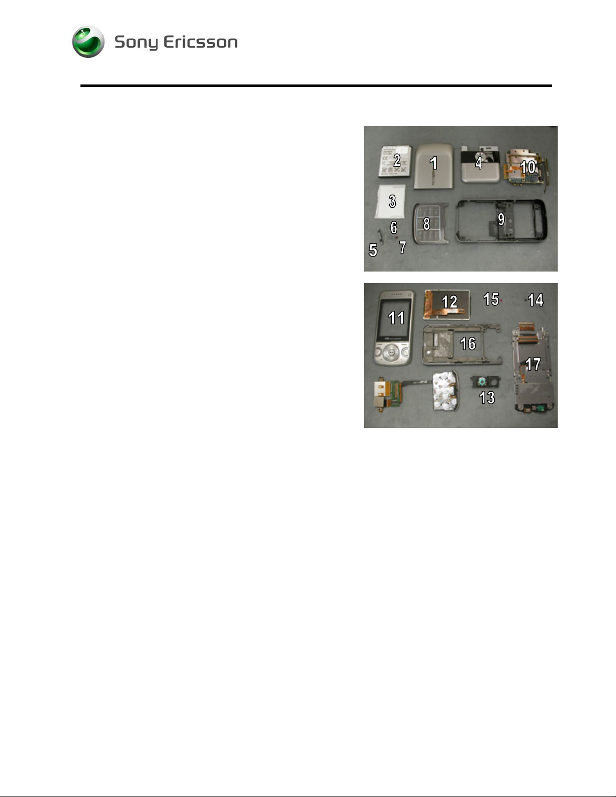
Disassemble in the following order:
Back Half
• Battery Cover (1)
• Battery (2)
• Label (3)
• Upper Back Cover (4)
• Volume Key (5)
• Back Screw (6)
• Middle Screws (7)
• Keyboard (8)
• Back Frame (9) from Hinge
• Circuit Board (10)
Front Half
• Front Cover (11)
• LCD (12)
• Ear Speaker Housing (13)
• Front Screw (14)
• Inner Screw (15)
• Front Frame (16) from Hinge (17)
1211-1553 1
Company Internal
Communications AB
© Sony Ericsson Mobile
Working Instruction, Mechanical
2.1 Standard Disassembly
This section must be completed before disassembling either half of the phone.
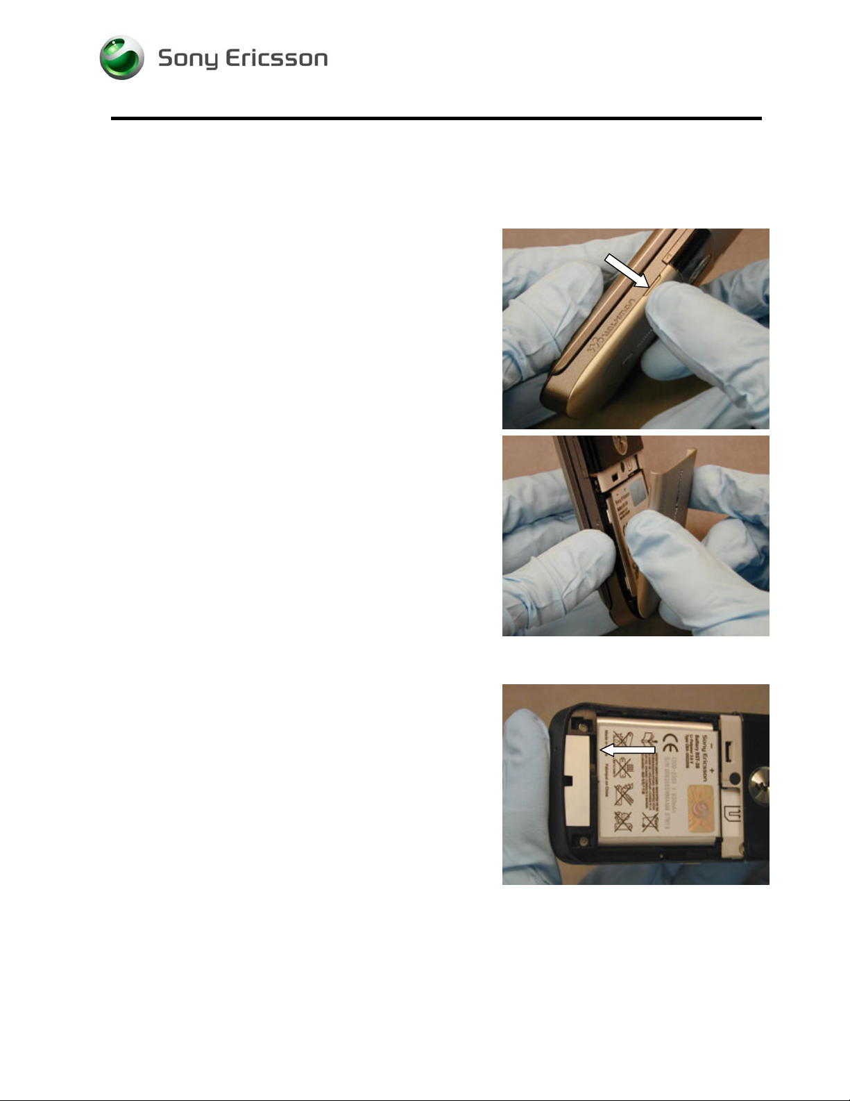
2.1.1 Battery Cover Removal
Lift up on the battery cover at its notch.
Remove battery cover.
2.1.2 Battery Removal
Using the indicated notch, lift the lower portion of the battery
from the battery cavity.
1211-1553 1
Company Internal
Communications AB
© Sony Ericsson Mobile
Working Instruction, Mechanical
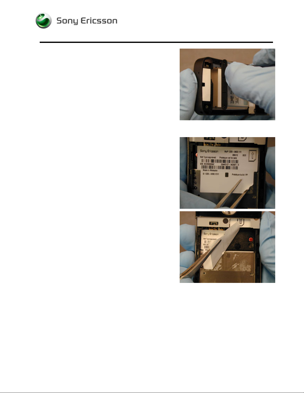
Remove battery.
2.1.3 Label Removal
Peel up the bottom right corner of the label using round
tipped tweezers.
Peel the label off.
OTE: DO NOT LET THE LABEL ADHESIVE TOUCH THE
N
BATTERY CONTACTS
.
Clean off any adhesive residue from the battery cavity using
alcohol and a lint-free wipe.
N
OTE: THE LABEL THAT HAS BEEN REMOVED SHOULD NOT BE
REUSED
!
1211-1553 1
© Sony Ericsson Mobile Communications AB
7(76)
Working Instruction, Mechanical
2.2 Back Half
2.2.1 Upper Back Cover Removal
Insert one end of the round tipped tweezers between the
upper back cover and the frame and push on the lower left
latch as shown.
Repeat for the right side latch.
Insert one tip of the round tipped tweezers between the
upper back cover and the frame on the SIM card holder
side of the middle latch and push to release it.
N
OTE: THE RF PORT COVER MAY FALL OUT.
While holding the bottom edge of the cover up, insert a
plectrum between the cover and the frame and push in at
an angle as shown to release the left side latch.
1211-1553 1
© Sony Ericsson Mobile Communications AB
8(76)
Working Instruction, Mechanical
Lift up on the upper back cover and rotate the free end
towards the side key to release it.
2.2.2 Volume Key Removal
Lift the side key from its opening using round tipped
tweezers.
2.2.3 Back Screw Removal
Remove the four back screws using a JCIS-0 bit.
OTE: DO NOT REUSE SCREWS!
N
1211-1553 1
© Sony Ericsson Mobile Communications AB
9(76)
Working Instruction, Mechanical
Remove the two middle screws using a JCIS-0 bit.
Note: Do not reuse screws!
1211-1553 1
© Sony Ericsson Mobile Communications AB
10(76)
Working Instruction, Mechanical
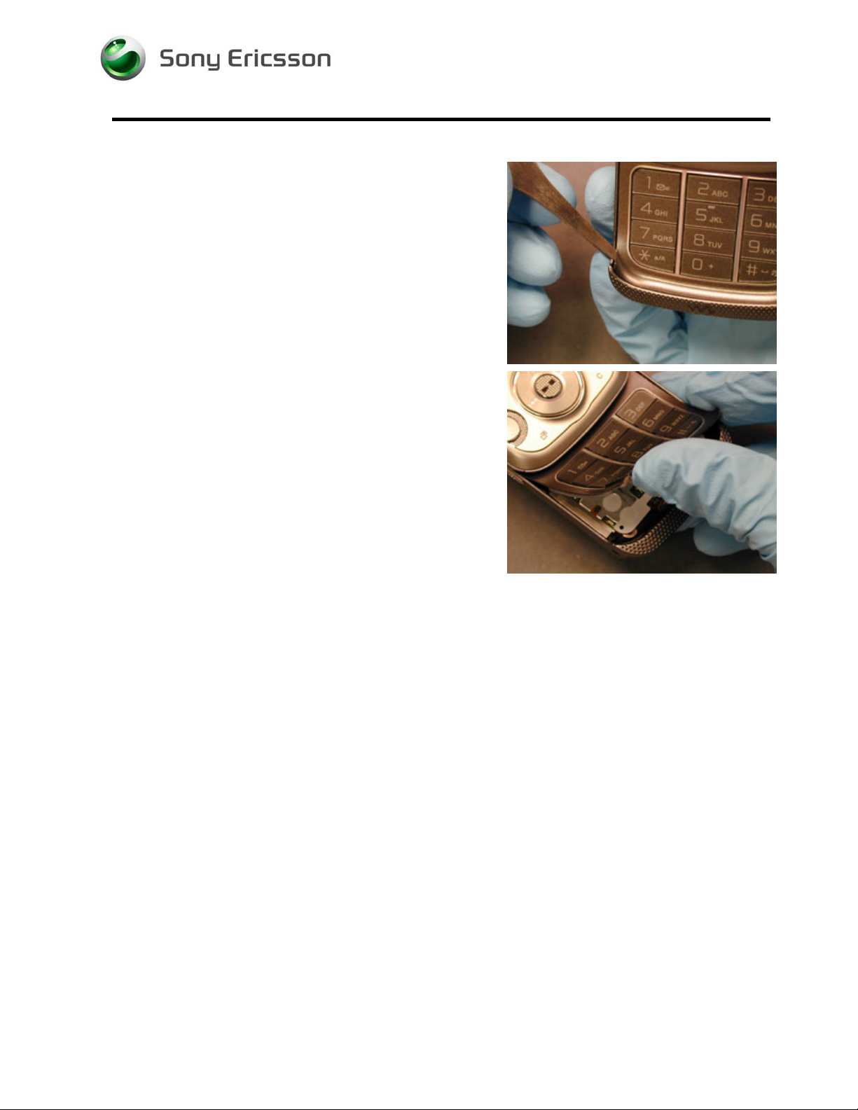
2.2.4 Keyboard Removal
Open the phone.
Insert one tip of the round tipped tweezers between the
keyboard and the hinge.
Lift up on the keyboard and peel it off.
OTE: CLEAN OFF ANY ADHESIVE RESIDUE.
N
OTE: DO NOT REUSE THE KEYBOARD.
N
1211-1553 1
© Sony Ericsson Mobile Communications AB
11(76)

Working Instruction, Mechanical
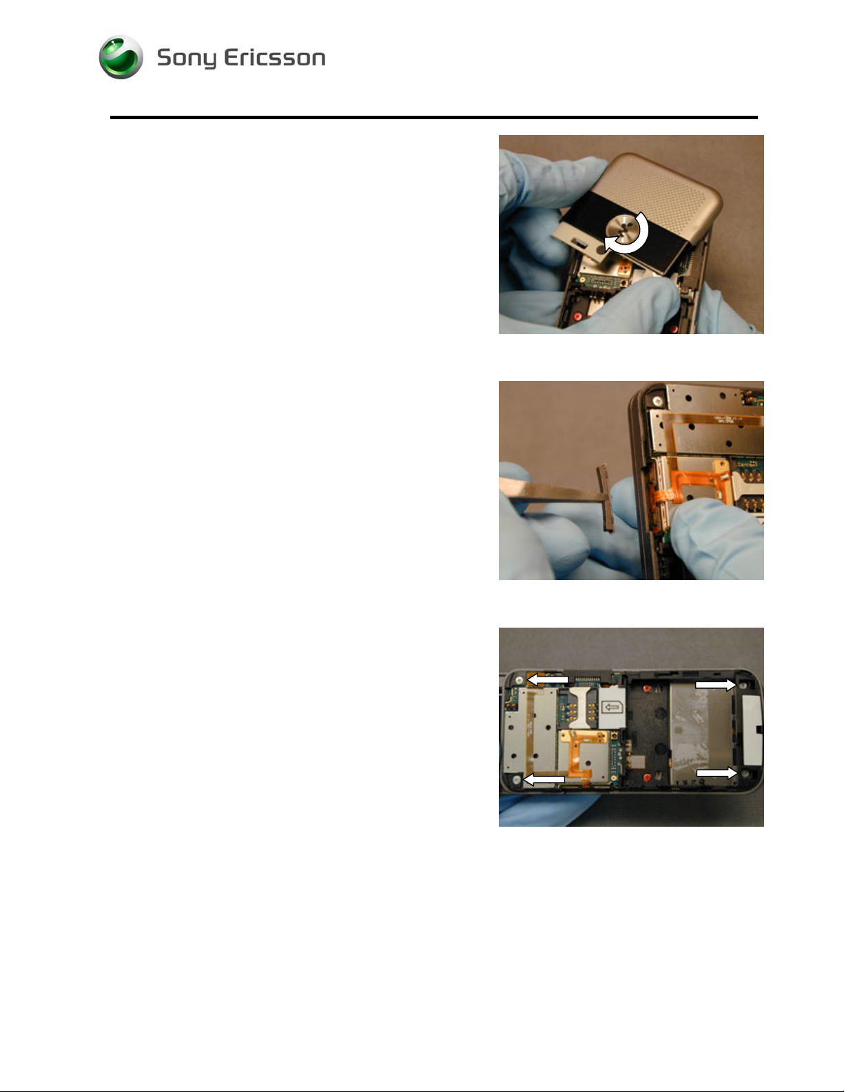
2.2.5 Back Frame Removal
Pry the upper right back frame latch from the hinge while
holding the phone as shown.
Insert the tip of round tipped tweezers between the back
frame and the hinge just below the right latch as shown.
Pry the hinge up to release the latch.
Repeat for the left latch.
1211-1553 1
© Sony Ericsson Mobile Communications AB
12(76)
Working Instruction, Mechanical
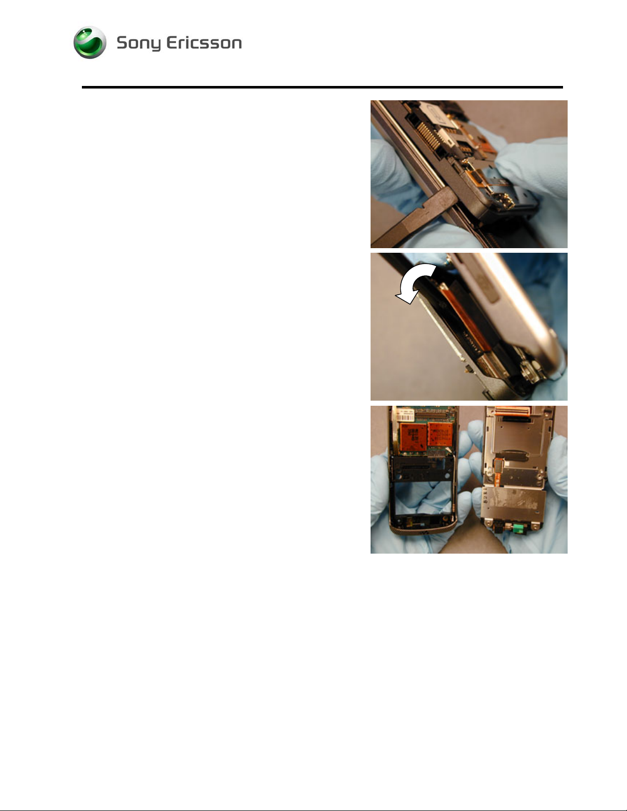
Pry the upper left back frame latch free so that you can see
the upper left portion of the hinge.
Insert the pry tool between the hinge and the back frame so
that the flat end of the tool is under the edge of the hinge
flex near one end of the flex connection.
Rotate the pry tool towards the back frame when prying the
hinge flex loose to avoid prying on components that are
located directly adjacent to the hinge connection.
Once the hinge flex is free, rotate the front half of the phone
from the back frame to separate the back frame from the
hinge.
N
OTE: THE MICROPHONE GASKET MAY NEED TO BE REMOVED
FROM THE BACK FRAME.
1211-1553 1
© Sony Ericsson Mobile Communications AB
13(76)
Working Instruction, Mechanical
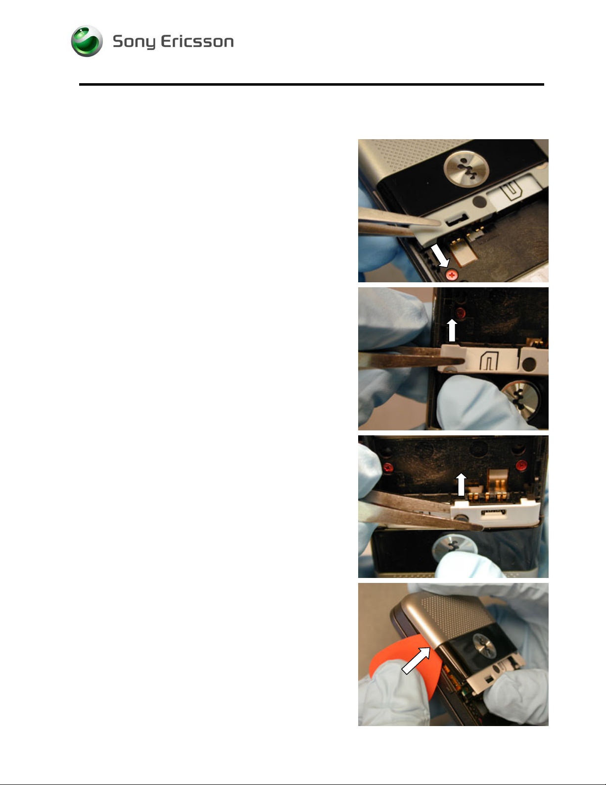
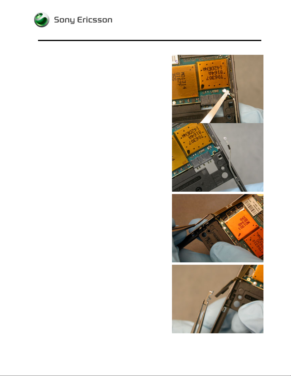
2.2.6 Circuit Board Removal
Disconnect the coax cable using round tipped tweezers and
position it out of the way as shown.
Lift the walkman key flex out of its position using round
tipped tweezers.
Remove the walkman key using round tipped tweezers.
1211-1553 1
© Sony Ericsson Mobile Communications AB
14(76)

Working Instruction, Mechanical
Insert one tip of the round tipped tweezers between the side
key flex and the frame to unadhere the flex.
Lift the side key flex out using round tipped tweezers.
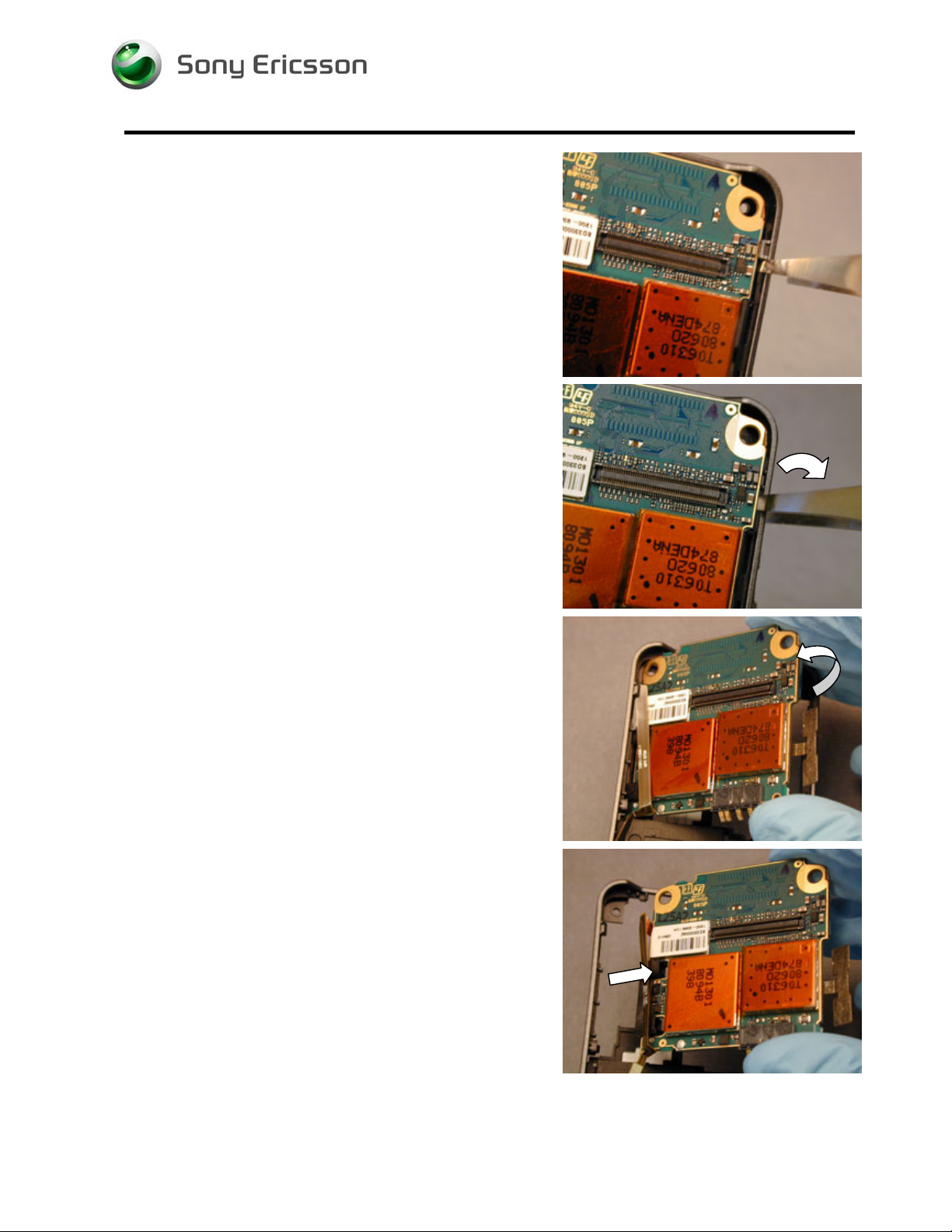
Insert one tip of round tipped tweezers between the back
frame just above the lower right latch and the circuit board
as shown.
Rotate the tweezers away from the board to release the
lower right latch.
1211-1553 1
© Sony Ericsson Mobile Communications AB
15(76)
Working Instruction, Mechanical
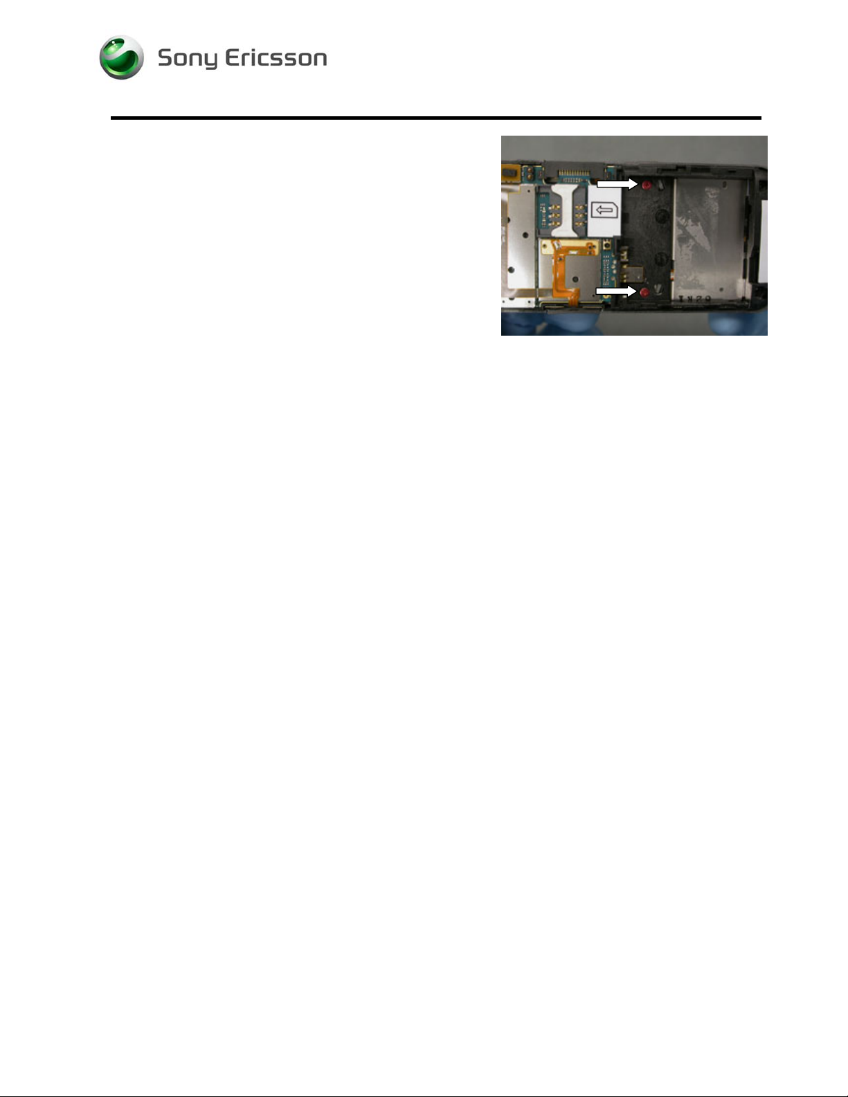
Insert one tip of round tipped tweezers between the frame
and circuit board just below the upper right latch.
Rotate the tweezers away from the board to release the
latch.
Rotate the right side of the board up.
Work the left side of the circuit board free from the rear
frame and remove the circuit board.
1211-1553 1
© Sony Ericsson Mobile Communications AB
16(76)
Working Instruction, Mechanical
2.3 Front Half
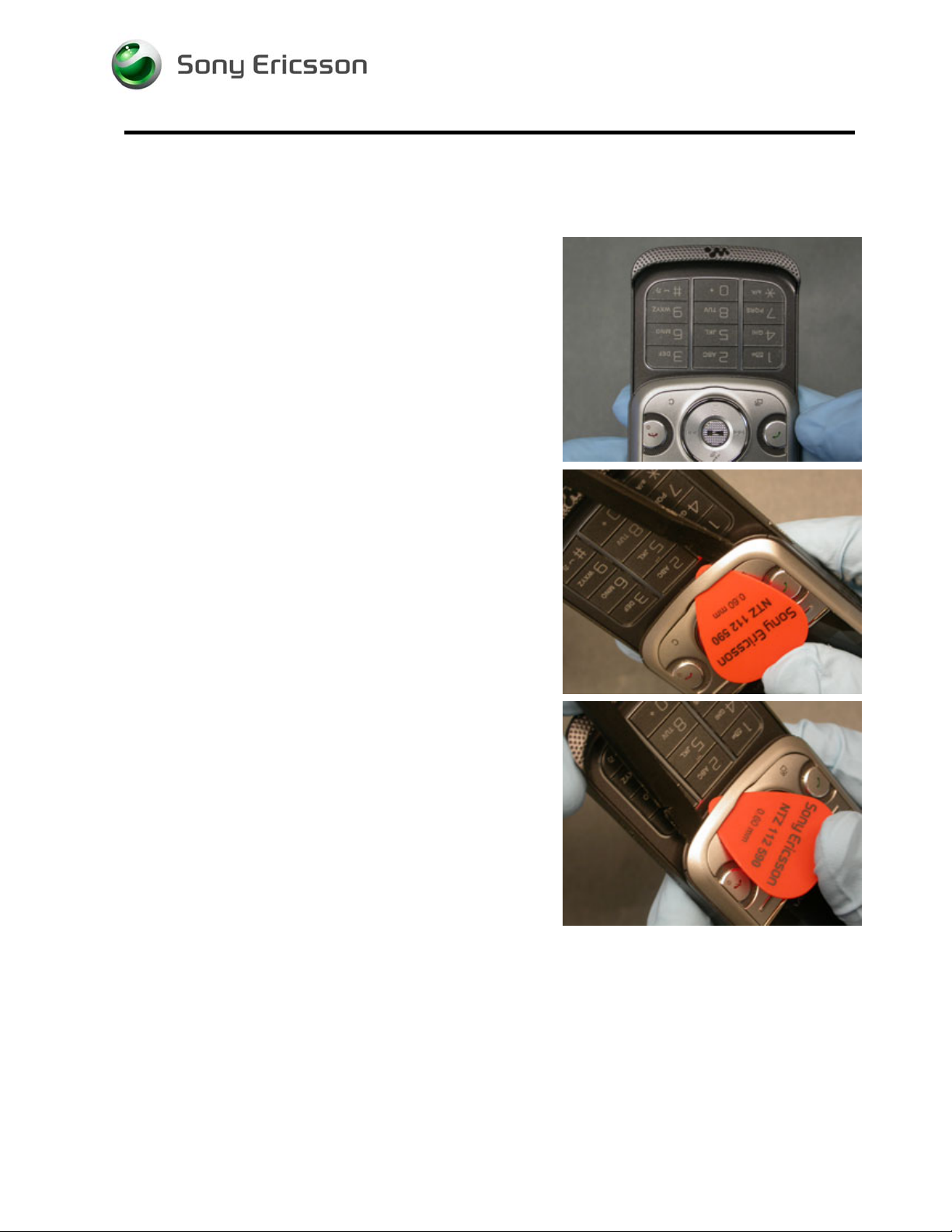
2.3.1 Front Cover Removal
Open the phone.
Slide the plectrum between the navigation keypad and the
front cover frame in the location shown to create a gap.
Use the pry tool to pry the lower left latch.
Repeat for the location shown.
1211-1553 1
© Sony Ericsson Mobile Communications AB
17(76)
Working Instruction, Mechanical
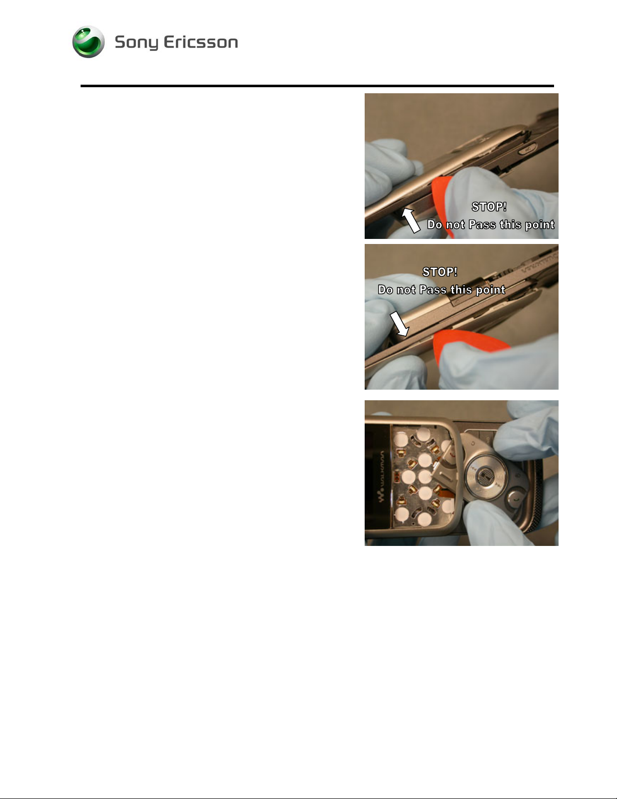
Slide the plectrum along the seam of one edge until you
reach the top of the back half.
N
OTE: IT IS IMPORTANT NOT TO SLIDE THE PLECTRUM ANY
FURTHER THAN INDICATED TO REDUCE RISK OF DAMAGE TO
FRONT COVER LATCHES
.
Repeat for the other side.
OTE: IT IS IMPORTANT NOT TO SLIDE THE PLECTRUM ANY
N
FURTHER THAN INDICATED TO REDUCE RISK OF DAMAGE TO
FRONT COVER LATCHES
.
Lift up on the bottom edge of the cover and remove the
navigation keypad.
1211-1553 1
© Sony Ericsson Mobile Communications AB
18(76)

Working Instruction, Mechanical
NOTE: IT IS IMPORTANT TO FOLLOW THE INSTRUCTIONS
EXACTLY TO REDUCE RISK OF DAMAGE TO THE FRONT COVER
AND FRAME
Lift up on the bottom edge of the cover and rotate it to the
left until the upper left side latch releases.
.
Then rotate the cover to the right to release the upper right
side latch.
Once both of the upper side latches are released, rotate the
front cover from the front frame by lifting front cover from
the bottom.
2.3.2 LCD Removal
Insert the flat end of the nylon pointer into the gap between
the LCD cushion and LCD latch on whichever side has a
larger gap and pry up.
1211-1553 1
© Sony Ericsson Mobile Communications AB
19(76)

Working Instruction, Mechanical
Rotate the top of the LCD away for the upper frame while
moving the bottom of the LCD towards the top of the phone.
Using a pry tool, disconnect the LCD from the NeoBon flex.
Lift the LCD from the phone.
2.3.3 Ear Speaker Housing Removal
Pry the left game button flex up using a pry tool.
1211-1553 1
© Sony Ericsson Mobile Communications AB
20(76)

Working Instruction, Mechanical
Pry the camera flex up using a pry tool and hold it back with
your thumb.
N
OTE: BE CAREFUL NOT TO CONTAMINATE THE ADHESIVE
RING THAT HOLDS THE CAMERA IN PLACE
.
Pry in the location shown with the tip of the nylon pointer to
pop the ear speaker housing out.
N
OTE: MAKE SURE TO ONLY PRY ON THE HOUSING AND NOT
M2 READER.
THE
OTE: AT THIS POINT YOU MAY WISH TO ADD A PROTECTIVE
N
COVER TO THE ADHESIVE RING THAT HOLDS THE CAMERA
.
2.3.4 Front Screw Removal
Slide the hinge closed slightly to reveal two front screws
and remove them using a JCIS-0 bit.
Slide the hinge more closed to reveal the remaining two
screws and remove them using a JCIS-0 bit.
1211-1553 1
© Sony Ericsson Mobile Communications AB
21(76)

Working Instruction, Mechanical
Return the phone to the open position.
2.3.5 Inner Screw Removal
Remove the two inner screws using a JCIS-0 bit.
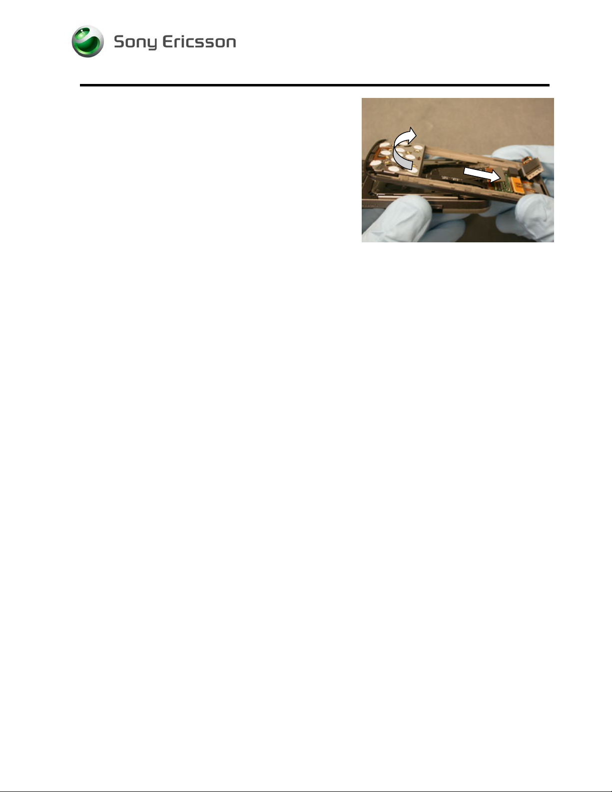
2.3.6 Front Frame Removal
Disconnect the Hinge flex from the NeoBon flex using a pry
tool.
1211-1553 1
© Sony Ericsson Mobile Communications AB
22(76)
Working Instruction, Mechanical
Rotate the bottom of the front frame away from the hinge,
then slide the front frame away from the hinge.
1211-1553 1
© Sony Ericsson Mobile Communications AB
23(76)
 Loading...