

Page 1

CME 20 R6.0/CMS 40 R2, CME 20 R6.1/CMS 40 R3
RBS 2301, RBS 2302
Reference Manual
EN/LZT 123 2697 R5A
Page 2

E
Reference Manual
Reference Manual
© Ericsson Radio Systems AB — All Rights Reserved —
EN/LZT 123 2697 R5A
1998-08-13
1 (306)
© Ericsson Radio Systems AB
— All Rights Reserved —
Page 3

Reference Manual
Due to continued progress in methodology, design and manufacturing
the contents of this document are subject to revision without notice.
2 (306)
EN/LZT 123 2697 R5A
1998-08-13
© Ericsson Radio Systems AB
— All Rights Reserved —
Page 4

Reference Manual
Contents
1 Preface...........................................................................................................11
1.1 Objectives................................................................................................11
1.2 Audience..................................................................................................12
1.3 Customer Documentation Library............................................................12
1.4 Release History.......................................................................................13
2 Site Configurations, RBS 2000 Micro.........................................................15
2.1 Terminology.............................................................................................15
2.2 System Overview.....................................................................................15
2.3 Configuration............................................................................................16
3 Radio Configurations, RBS 2000 Micro......................................................21
3.1 References...............................................................................................21
3.2 Terminology.............................................................................................21
3.3 Frequency Bands.....................................................................................23
3.4 General....................................................................................................24
3.5 Configurations..........................................................................................24
3.6 Basic Configuration GSM 900 MHz, M9d_2.2........................................28
3.7 Basic Configuration GSM 900 MHz, M9d_1.2........................................30
3.8 Basic Configuration GSM 1800 MHz, M18d_2.2....................................31
3.9 Basic Configuration GSM 1800 MHz, M18d_1.2....................................33
3.10 Basic Configuration GSM 1900 MHz, M19d_2.2..................................34
3.11 Basic Configuration GSM 1900 MHz, M19d_1.2..................................36
4 Product Specification for RBS 2301...........................................................37
4.1 General....................................................................................................37
4.2 Product Architecture................................................................................39
4.3 Configuration............................................................................................42
4.4 Combinations...........................................................................................43
4.5 Transmission Modes................................................................................44
4.6 Interface and Connection........................................................................45
4.7 Product Requirements.............................................................................46
4.8 Future Expansion.....................................................................................53
EN/LZT 123 2697 R5A
1998-08-13
3 (306)
© Ericsson Radio Systems AB
— All Rights Reserved —
Page 5

Reference Manual
5 Product Specification for RBS 2302...........................................................55
5.1 Terminology.............................................................................................55
5.2 General....................................................................................................55
5.3 Product Architecture................................................................................57
5.4 Configurations..........................................................................................59
5.5 Combinations...........................................................................................62
5.6 Transmission Modes................................................................................62
5.7 Interface and Connection........................................................................63
5.8 Product Requirements.............................................................................65
5.9 Future Expansion.....................................................................................71
6 Product Specification for Power and Battery Cabinet ............................73
6.1 Terminology.............................................................................................73
6.2 General....................................................................................................73
6.3 Product Architecture................................................................................74
6.4 Configurations..........................................................................................75
6.5 Combinations...........................................................................................76
6.6 Interface and Connection........................................................................76
6.7 Product Requirements.............................................................................79
7 Broadcast.......................................................................................................91
7.1 References...............................................................................................91
7.2 Concepts..................................................................................................91
7.3 Functions.................................................................................................91
8 Physical Channel Handling..........................................................................95
8.1 References...............................................................................................95
8.2 Functions.................................................................................................95
9 Base Station Power Control........................................................................99
9.1 References...............................................................................................99
9.2 Concepts..................................................................................................99
9.3 Functions.................................................................................................99
9.4 Operational Conditions............................................................................100
10 Channel Measurements..............................................................................101
4 (306)
EN/LZT 123 2697 R5A
1998-08-13
© Ericsson Radio Systems AB
— All Rights Reserved —
Page 6

Reference Manual
10.1 References.............................................................................................101
10.2 Concepts................................................................................................101
10.3 Functions...............................................................................................101
10.4 Operational Conditions..........................................................................103
11 Discontinuous Transmission.....................................................................105
11.1 References.............................................................................................105
11.2 Functions...............................................................................................105
12 Encryption....................................................................................................109
12.1 References.............................................................................................109
12.2 Functions...............................................................................................109
13 Frequency Hopping ...................................................................................111
13.1 References.............................................................................................111
13.2 Concepts................................................................................................111
13.3 Function.................................................................................................111
13.4 Operational Conditions..........................................................................112
14 Mode Modify ...............................................................................................113
14.1 References.............................................................................................113
14.2 Function.................................................................................................113
14.3 Operational Conditions..........................................................................114
15 Mobile Station Power Control....................................................................115
15.1 References.............................................................................................115
15.2 Functions...............................................................................................115
16 Short Message Service...............................................................................117
16.1 References.............................................................................................117
16.2 Functions...............................................................................................117
16.3 Operational Conditions..........................................................................119
17 Diversity Supervision.................................................................................121
17.1 References.............................................................................................121
17.2 Concepts................................................................................................121
17.3 Function.................................................................................................122
17.4 Operational Conditions..........................................................................123
EN/LZT 123 2697 R5A
1998-08-13
5 (306)
© Ericsson Radio Systems AB
— All Rights Reserved —
Page 7

Reference Manual
18 Synchronization..........................................................................................125
18.1 References.............................................................................................126
18.2 Concepts................................................................................................126
18.3 Functions...............................................................................................126
18.4 Operational Conditions..........................................................................128
19 Radio Reception..........................................................................................131
19.1 References.............................................................................................131
19.2 Concepts................................................................................................131
19.3 Functions...............................................................................................132
19.4 Operational Conditions..........................................................................132
20 Radio Transmission....................................................................................135
20.1 References.............................................................................................135
20.2 Concepts................................................................................................135
20.3 Functions...............................................................................................136
20.4 Operational Conditions..........................................................................137
21 Restart and Recovery.................................................................................139
21.1 Concepts................................................................................................139
21.2 Functions...............................................................................................140
21.3 Operational Conditions..........................................................................142
22 Function Change.........................................................................................143
22.1 Concepts................................................................................................143
22.2 Functions...............................................................................................144
22.3 Operational Conditions..........................................................................145
23 Functionality Administration.....................................................................147
23.1 Concepts................................................................................................147
23.2 Functions...............................................................................................148
23.3 Operational Conditions..........................................................................151
24 Operation and Maintenance Support........................................................153
24.1 Concepts................................................................................................153
24.2 Functions...............................................................................................154
25 Installation Data Handling..........................................................................159
6 (306)
EN/LZT 123 2697 R5A
1998-08-13
© Ericsson Radio Systems AB
— All Rights Reserved —
Page 8

Reference Manual
25.1 Concepts................................................................................................159
25.2 Functions...............................................................................................160
25.3 Operational Conditions..........................................................................161
26 Self Test and Supervision..........................................................................163
26.1 Concepts................................................................................................163
26.2 Self Test.................................................................................................163
26.3 Supervision............................................................................................163
27 Diagnostics and Fault Handling................................................................165
27.1 Concepts................................................................................................165
27.2 Functions...............................................................................................165
27.3 Operational Conditions..........................................................................167
28 Operation and Maintenance Terminal.......................................................169
28.1 References.............................................................................................169
28.2 Concepts................................................................................................169
28.3 Functions...............................................................................................170
28.4 Operational Conditions..........................................................................176
29 External Alarms...........................................................................................177
29.1 Concepts................................................................................................177
29.2 Function.................................................................................................177
29.3 Operational Conditions..........................................................................178
30 Power Supply..............................................................................................179
30.1 References.............................................................................................179
30.2 Concepts................................................................................................179
30.3 Functions...............................................................................................180
30.4 Operational Conditions..........................................................................180
31 Climate Protection......................................................................................183
31.1 Concepts................................................................................................183
31.2 Functions...............................................................................................184
32 Transmission Interface Handling G.703 2048 kbit/s...............................187
32.1 References.............................................................................................187
32.2 Concepts................................................................................................187
EN/LZT 123 2697 R5A
1998-08-13
7 (306)
© Ericsson Radio Systems AB
— All Rights Reserved —
Page 9

Reference Manual
32.3 Functions...............................................................................................189
32.4 Operational Conditions..........................................................................197
33 Transmission Interface Handling DS1 1544 kbit/s..................................199
33.1 References.............................................................................................199
33.2 Concepts................................................................................................199
33.3 Functions...............................................................................................201
34 Terrestrial Link Handling............................................................................215
34.1 References.............................................................................................215
34.2 Concepts................................................................................................215
34.3 Function.................................................................................................215
34.4 Operational Conditions..........................................................................215
35 Channel Distribution Function..................................................................217
35.1 References.............................................................................................217
35.2 Concepts................................................................................................217
35.3 Functions...............................................................................................218
35.4 Operational conditions...........................................................................227
36 Common Control Channel Handling.........................................................229
36.1 References.............................................................................................229
36.2 Function.................................................................................................229
36.3 Operational Conditions..........................................................................233
37 Speech and Data Services.........................................................................235
37.1 References.............................................................................................235
37.2 Concepts................................................................................................235
37.3 Functions...............................................................................................236
37.4 Operational Conditions..........................................................................240
38 Call Control..................................................................................................243
38.1 References.............................................................................................243
38.2 Concepts................................................................................................243
38.3 Functions...............................................................................................244
38.4 Operational Conditions..........................................................................251
39 EMC Capabilities for RBS 2301.................................................................255
8 (306)
EN/LZT 123 2697 R5A
1998-08-13
© Ericsson Radio Systems AB
— All Rights Reserved —
Page 10

Reference Manual
39.1 References.............................................................................................255
39.2 Concepts................................................................................................256
39.3 Capabilities............................................................................................258
40 EMC Capabilities for RBS 2302.................................................................263
40.1 References.............................................................................................263
40.2 Concepts................................................................................................266
40.3 Emission................................................................................................268
40.4 Immunity................................................................................................270
41 Environmental Capabilities........................................................................277
41.1 Scope.....................................................................................................277
41.2 Terminology...........................................................................................277
41.3 References.............................................................................................278
41.4 Transport -40
C - +70C........................................................................278
41.5 Storage -25
C - +55C...........................................................................279
41.6 Handling -40
C - +70C.........................................................................281
41.7 Operation Mast Mounted Equipment -33
C - +45C.............................281
42 Product Safety Requirements RBS 2000..................................................285
42.1 References.............................................................................................285
42.2 Product Safety.......................................................................................285
43 Building Practice Requirements RBS 2000..............................................287
43.1 Fire Resistance......................................................................................287
43.2 Poisonous Fumes..................................................................................288
43.3 Declaration of Materials.........................................................................288
43.4 Silicone..................................................................................................288
43.5 Environmental Consideration during the Life-Cycle..............................288
44 BTS Parameter Limitations........................................................................289
44.1 Purpose and Readers............................................................................289
44.2 Terminology...........................................................................................289
44.3 References.............................................................................................289
44.4 Parameters............................................................................................289
44.5 Appendix................................................................................................295
EN/LZT 123 2697 R5A
1998-08-13
9 (306)
© Ericsson Radio Systems AB
— All Rights Reserved —
Page 11

Reference Manual
45 Glossary.......................................................................................................297
10 (306)
EN/LZT 123 2697 R5A
1998-08-13
© Ericsson Radio Systems AB
— All Rights Reserved —
Page 12

Preface
1 Preface
This manual is valid for CME 20 R6.0/ CMS 40 R2 and CME 20 R6.1/
CMS 40 R3.
1.1 Objectives
The manual is intended as an overview of the Ericsson micro base
stations for the GSM 900 MHz, GSM 1800 MHz and GSM 1900 MHz.
The manual is divided into:
• General Information:
Preface
• Supported Configurations:
The chapters gives an overview of supported site configurations
including earthing principles, battery backup times etc. and radio
configurations with characteristics and capacity for each
configuration
• Specifications for the basestations and complementary products:
The chapters describes the architecture and specifies the
characteristics and performance of each product.
• Function Specifications:
Provides detailed information about the basestations from a
functional point of view. The Function Specifications are
customer-adapted and give a deeper understanding of the behavior
of the basestations.
• BTS Parameter Limitations:
States configurable BTS parameters for RBS 2000. BTS
parameters with limitations compared with the parameter ranges
in the Abis O&M IWD are stated in this section.
• Glossary:
List of Abbreviations.
EN/LZT 123 2697 R5A
1998-08-13
11 (306)
© Ericsson Radio Systems AB
— All Rights Reserved —
Page 13
Preface
1.2 Audience
Customer and Ericsson personnel involved in radio base station
activities.
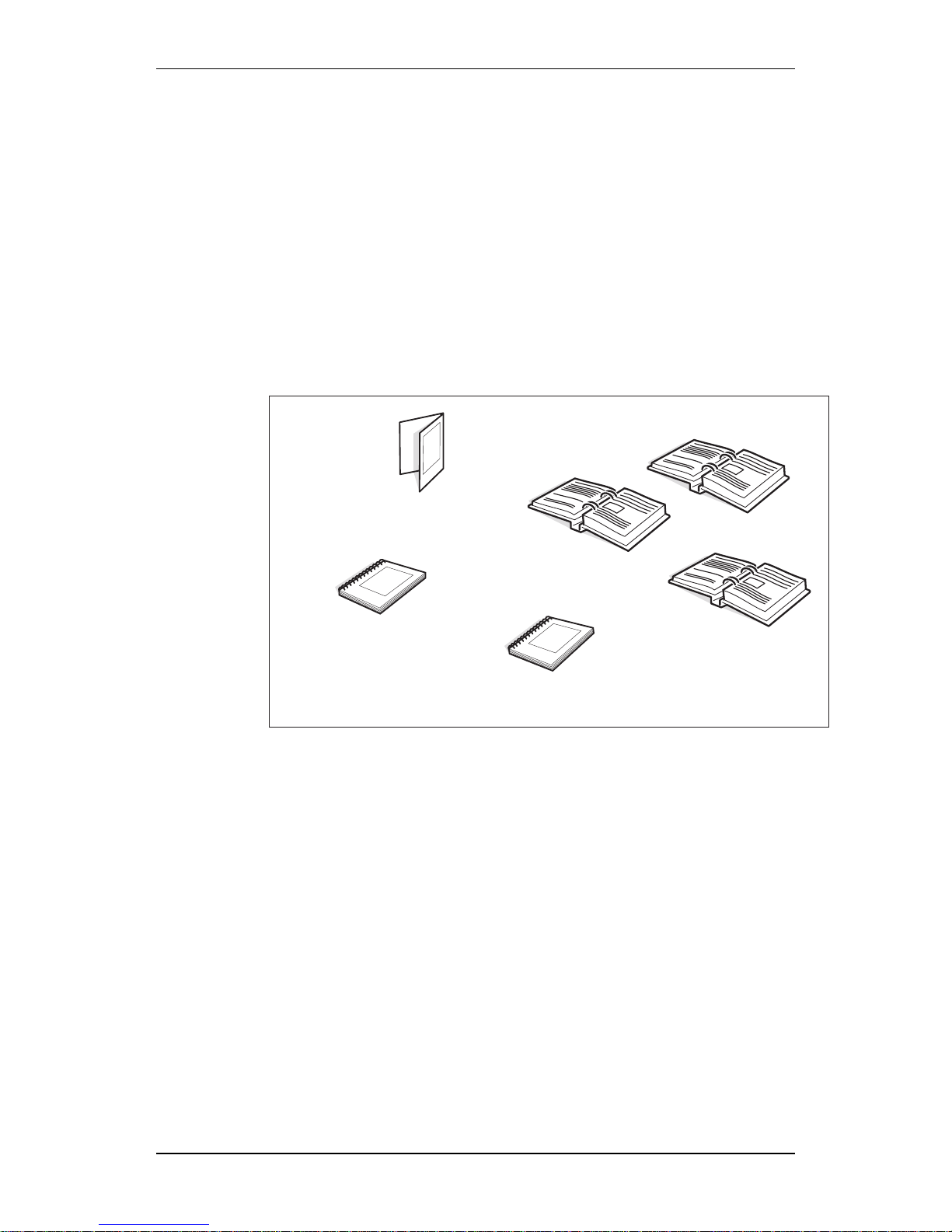
1.3 Customer Documentation Library
The user documentation for RBS 2301, RBS 2302 and MAXITE
TM
consists of customer manuals and procedures divided up to suit different
process events. The Library Overview contains the following
information for each manual:
• Short description
• Recommendation of appropriate target group
• Product number
P003651A
Reference Manual
RBS 2301
User´s Guide
General Installation
Instructions
xx xxx
x x x
xxxx xxx xxxx xxx xxx xxx
xxx xxx xxx xxx xx xxx xxx
xxxx xx
x x x x xxxx xxx xxxx
xxx xxx xxx xxx xxx xxx xxx
xx xxx xxx xxxx xxx x x x
xxxx xxx xxxx xxx xxx xxx
xxx xxx xxx xxx xx xxx xxx
xxxx xxx x x x xxxx xxx
xxxx xxx xxx xxx xxx xxx
xxx xxx xx xxx xxx
xxxx xxx x x x xxxx
xxx xxxx xxx xxx xxx xxx
xxx xxx xxx xx xxx xxx xxxx
xxx x x x xxxx xxx xxxx
xxx xxx xxx xxx xxx xxx xxx
xx xxx xxx xxxx xxx x x x
xxxx xxx xxxx xxx xxx xxx
xxx x xx xxx xxx xx xxx
xxx xxxx xxx x x x xxxx
xxx xxxx xxx xxx xxx xxx
xxx xxx xxx xx xxx xxx xxxx
xxx x x x xxxx xxx xxxx
xxx xxx xxx xxx xxx xxx xxx
Library Overview
RBS 2302
User´s Guide
Maxite
User´s Guide
Figure 1 The Customer documentation library
12 (306)
EN/LZT 123 2697 R5A
1998-08-13
© Ericsson Radio Systems AB
— All Rights Reserved —
Page 14

Preface
1.4 Release History
Except editorial changes such as correction of spelling, grammar and
layout, this manual has been revised as follows:
1.4.1 R4A to R5A
Table 1
Chapter Chapter heading Revised
sections and
sub-sections
Description
1 Preface 1.1 Objectives and figure "The Customer
Documentation Library" updated.
1.4.1 Release History for R3A to R4A deleted
and exchanged for R4A to R5A.
2 Site Configurations, RBS 2000 Micro A new chapter added
3 General Specification for RBS 2000
Micro Configurations
Renamed to Radio Configurations,
RBS 2000 Micro. Technical data
concerning the RBS 2302 added.
5 Product Specification for RBS 2302 A new chapter added
6 Product Specification for Power and
Battery Cabinet
A new chapter added
12 Encryption 12.2.3 Section "Encryption Mode Change at
Mode Modify" added
20 Radio Transmission 20.3.4 TX Diversity: "Transmitter diversity..."
rewritten
29 External Alarms 29.3.2 RBS 2302, External alarms, maximum: 8
added
31 Climate Protection 31.2.1 Natural Convection renamed to Convection
39 EMC Capabilities Chapter renamed from "EMC Capabilities"
to "EMC Capabilities for RBS 2301"
40 EMC Capabilities for RBS 2302 A new chapter added
41 Environmental Capabiblities "RBS 2301" was removed from the title
Note: Chapters not listed in the table are unchanged.
EN/LZT 123 2697 R5A
1998-08-13
13 (306)
© Ericsson Radio Systems AB
— All Rights Reserved —
Page 15

Preface
This page is intentionally left blank
14 (306)
EN/LZT 123 2697 R5A
1998-08-13
© Ericsson Radio Systems AB
— All Rights Reserved —
Page 16

Site Configurations, RBS 2000 Micro
2 Site Configurations, RBS 2000 Micro
2.1 Terminology
AC box The AC box splits the incoming mains to
the site to different AC users in the site.
This is external equipment that is
delivered by the local support organization
in each country or region.
Interfaces There are a number of interfaces in the
system: AC mains, DC 24 V, DC –48 V,
External alarms, Alarms, Data,
Transmission, T,X,L-bus, RF Feeders
N/A Not Applicable
Mini Link E-micro Mini Link E-micro is a transmission unit
that sends transmission via the radio
interface.
MLPU Mini Link Lightning Protection Unit
PBC Power Battery Cabinet
The PBC converts AC mains to 24 V and
–48 V. It includes battery backup for RBS
and AAU.
R1P1A1RL1PL1AL1/M1 Configuration with: 1 RBS, 1 PBC, 1
AAU, 1 RLPU, 1 PLPU, 1 ALPU and
optional 1 Mini Link
RBS 2302 RBS 2302 is a radiobasestation based on
the RBS 2301. It is developed for 6 TRX
functionality and prepared for MAXITE
TM
installations.
t
ext
means External temperature
2.2 System Overview
2.2.1 Site Configurations Overview
The tables below describe the different site configurations for RBS 2302
products.
Fan units and Mini Link configurations are considered to be optional
and therefore marked with a “slash” ( / ), for example “/RF1” or ”/M1”).
Table 2 RBS 2302 Site Configurations
Short no. Slogan RBS 2302 PBC Fan Unit Mini Link
(R) (P) (RF,PF) (M)
R1 2 TRX 1 /RF1
R2 4 TRX 2 /RF2
EN/LZT 123 2697 R5A
1998-08-13
15 (306)
© Ericsson Radio Systems AB
— All Rights Reserved —
Page 17
Site Configurations, RBS 2000 Micro
R3 6 TRX 3 /RF3
R1P1 2 TRX external
backup
1 1 /RF1 /M1
R2P2 4 TRX external
backup
2 2 /RF2 /M1
R3P3 6 TRX external
backup
3 3 /RF3 /M1
Note: Not all configurations are described with a figure.
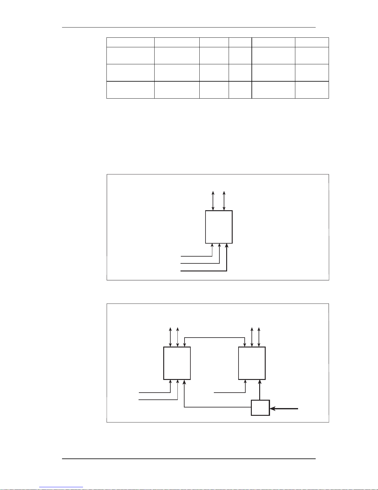
2.3 Configuration
2.3.1 Site Configurations
RBS 2302 Configurations
P0035018
RBS 2302
Feeders to passive antenna
Transmission
Ext. alarms
AC Mains
Figure 2 2 TRX (R1)
P0035019
RBS 2302
Feeders to
passive antenna
Transmission
Ext. alarms
RBS 2302
Feeders to
passive antenna
Ext. alarms
AC Mains
AC
box
T, X, L -bus
Figure 3 4 TRX (R2)
16 (306)
EN/LZT 123 2697 R5A
1998-08-13
© Ericsson Radio Systems AB
— All Rights Reserved —
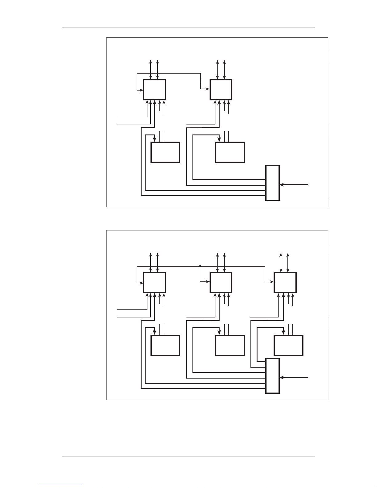
Page 18

Site Configurations, RBS 2000 Micro
P0035021
RBS 2302
Feeders to
passive antenna
Transmission
Ext. alarms
RBS 2302
Feeders to
passive antenna
Ext. alarms
AC Mains
T, X, L -bus
RBS 2302
Feeders to
passive antenna
Ext. alarms
AC
box
Figure 4 6 TRX (R3)
RBS 2302 Configurations with backup
P0035020
RBS 2302
Feeders to
passive antenna
Transmission
Ext. alarms
PBC
Alarms
AC Mains
AC
box
DC 24V
Figure 5 Extended backup, 2 TRX (R1P1)
EN/LZT 123 2697 R5A
1998-08-13
17 (306)
© Ericsson Radio Systems AB
— All Rights Reserved —
Page 19
Site Configurations, RBS 2000 Micro
P003523
PBC1
AC
box
AC Mains
Alarms
Ext. alarms
Transmission
RBS
2302
PBC2
T, X, L - bus
DC 24V
Alarms
DC 24V
RBS
2302
Feeders to
passive antenna
Feeders to
passive antenna
Ext. alarms
Figure 6 Extended backup, 4 TRX (R2P2)
P003522
PBC1
AC
box
AC Mains
Alarms
Ext. alarms
Transmission
RBS
2302
PBC2
T, X, L - bus
DC 24V
PBC3
Alarms
DC 24V
RBS
2302
RBS
2302
Ext. alarms
Alarms
DC 24V
Feeders to
passive antenna
Feeders to
passive antenna
Feeders to
passive antenna
Ext. alarms
Figure 7 Extended backup, 6 TRX (R3P3)
18 (306)
EN/LZT 123 2697 R5A
1998-08-13
© Ericsson Radio Systems AB
— All Rights Reserved —
Page 20

Site Configurations, RBS 2000 Micro
+55C Configurations
P0035014
AC
box
Ext. alarms
Transmission
Alarms
RBS
fan unit
Feeders to
passive antenna
AC Mains
RBS 2302
Figure 8 2 TRX, +55C (R1/RF1)
EN/LZT 123 2697 R5A
1998-08-13
19 (306)
© Ericsson Radio Systems AB
— All Rights Reserved —
Page 21

Site Configurations, RBS 2000 Micro
This page is intentionally left blank
20 (306)
EN/LZT 123 2697 R5A
1998-08-13
© Ericsson Radio Systems AB
— All Rights Reserved —
Page 22

Radio Configurations, RBS 2000 Micro
3 Radio Configurations, RBS 2000 Micro
This chapter describes the RBS 2000 Micro Radio Configurations and
their associated performances.
3.1 References
/GSM:05.05/ GSM 05.05 (phase 2) version 4.13.0
/PCS/ The references /PCS:1-8/ are chapters in
the document:
Volume 1, PCS 1900 Physical Layer 1
Specification marked:
JTC(AIR)94.08.01-231R3
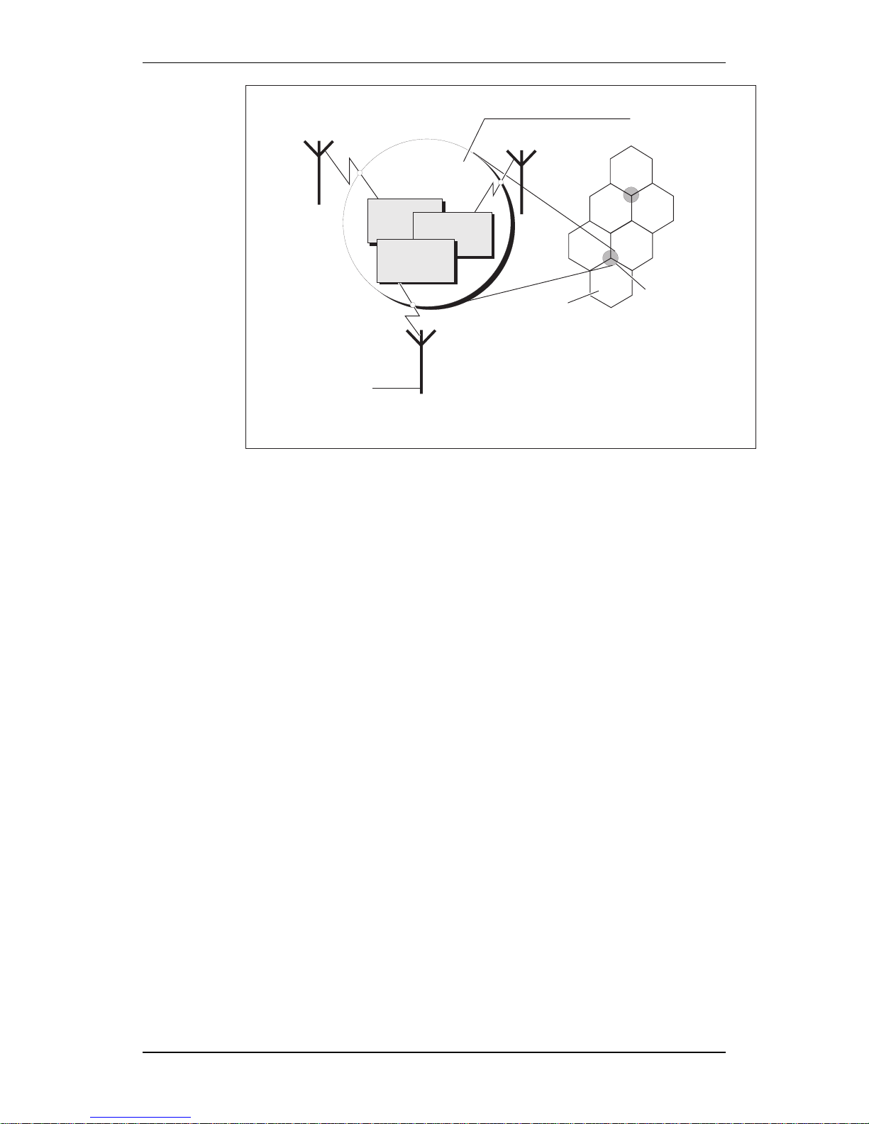
3.2 Terminology
3.2.1 The Mobile Telephone System
Figure 9 RBS 2000 in Ericsson’s GSM System
The BSS (Base Station System) contains two functional entities:
• The BSC (Base Station Controller) handles the radio-related
functions such as hand over, management of the radio network
resources, and cell configuration data. It also controls radio
frequency power levels in base stations and mobile stations.
• The BTS (Base Transceiver Station) is the radio equipment needed
to serve one cell. It consists of the antenna system, the radio
frequency power amplifiers and all the digital signal processing
equipment. RBS 2000 contains equipment for 1 − 3 BTSs.
EN/LZT 123 2697 R5A
1998-08-13
21 (306)
© Ericsson Radio Systems AB
— All Rights Reserved —
Page 23
Radio Configurations, RBS 2000 Micro
Transport network
Antenna
system
BTS Base Transceiver Subsystem
Site
Cell
BTS
BTS
BTS
01_0388A
RBS 2000
Figure 10 An RBS 2000 site with three cells
3.2.2 Antenna System
Is constituted by all RF transmission and reception antennas, directed to
cover the same area or multicasting configuration.
Antenna Reference Point (ARP)
Two ARP are defined in this document; the RBS ARP and
the AAU V
(1)
-ARP.
The RBS ARP is the feeder connector on the RBS.
The AAU V-ARP is the test connector after the network that connects
the outputs from different PAM:s. This network is used for test
purposes only.
(1)
V=Virtual
3.2.3 Basic Configuration
A maximum of two transceivers can be combined and connected to one
antenna system.
The basic configuration may be multiplied or used in combination with
other basic configurations to build the needed site equipment.
3.2.4 Definition
The definition of the basic configuration type thus refers to CDU_type.
<Basic_Config>::=<X><F>d_<A>.<T>\<N>
22 (306)
EN/LZT 123 2697 R5A
1998-08-13
© Ericsson Radio Systems AB
— All Rights Reserved —
Page 24

Radio Configurations, RBS 2000 Micro
P003437A
CDU type (M=micro)
Frequency band (900, 1800, 1900)
Filter (d=duplex)
Number of antenna ports
Number of transcievers
Active Antenna (A) or Highway (H) config.
M 9 d _ 2 . 2 / N
Figure 11 Type definition example
Type definitions:
<N> ::= <Variant> ::= A, H
A = Active Antenna
H = Active Antenna Highway Congifuration
<X> ::= <Basic CDU-type> ::=M
M = Microbase RBS
<F> ::= <Frequency Band> ::=9/18/19
9 = 900 MHz
18 = 1800 MHz
19 = 1900 MHz
<option>::=d
d: = Duplexer included in CDU
<A> ::= <No of Antenna Ports>
<T> ::= <No of Transceivers>
3.3 Frequency Bands
Uplink 890 - 915 MHz
GSM 900
Downlink 935 - 960 MHz
Uplink 1710 - 1785 MHz
GSM 1800
Downlink 1805 - 1880 MHz
Uplink 1850 - 1910 MHz
GSM 1900
Downlink 1930 - 1990 MHz
EN/LZT 123 2697 R5A
1998-08-13
23 (306)
© Ericsson Radio Systems AB
— All Rights Reserved —
Page 25

Radio Configurations, RBS 2000 Micro
3.4 General
RBS Configurations is the designated expression for the RF parts
integrated in the BTS.
The functionality is:
• The output signal from one or more transmitters are combined
into the same antenna system, which can be utilized as a TX/RX
antenna.
• The received signal from the receive antenna system, which can
be utilized as a TX/RX antenna, is distributed to receivers
belonging to one RBS.
3.5 Configurations
3.5.1 TX Output Power
The value given for the RBS output power for the different
configurations below is the minimum RBS output power when the
transmitter is set for maximum nominal power (P0).
The RBS output power is measured at the TX reference point, and it is
dependent on the TX combining and filtering parts.
The tolerance for the RBS output power at the different settings is in
compliance with /GSM:05.05:4.1.2/ for GSM 900 and GSM 1800, and /
PCS:5.3.3/ for GSM 1900.
When two or more transmitters are combined to one antenna, the
transmitters must be operated with a minimum of 400 kHz separation
between the centre frequency of adjacent carriers. This limitation is not
caused by the combiner but the RBS itself.
With TX diversity configured both transmitters use the same ARFCN.
The maximum nominal power, P0, measured on the cabinet output RF
connector (which in this case corresponds to the TX Reference Point) is
minimum +32 dBm. This output power level is valid for all frequency
bands.
With TX diversity configured the output power is minimum +32 dBm at
each ARP.
Nominal A-bis configuration power parameters for the Micro Base
Station RBS 2301:
900 MHz 21 - 33 (dec)
1800 MHz 21 - 33 (dec)
1900 MHz 21 - 33 (dec)
Note: Only steps by 2 is configureable (from the highest value).
TX diversity configuration power parameters for the Micro Base Station
RBS 2301:
24 (306)
EN/LZT 123 2697 R5A
1998-08-13
© Ericsson Radio Systems AB
— All Rights Reserved —
Page 26

Radio Configurations, RBS 2000 Micro
1800 MHz: 36 (dec)
1900 MHz: 36 (dec)
3.5.2 RX Description
The receiver system performance is dependent on the configuration.
Actual sensitivity level
Is defined in and complying with the level where RBS meets the
reference sensitivity performance defined in:
- /GSM:05.05:6.2 / for GSM 900 and GSM 1800
- /PCS:4/ and /PCS:5.1.1/ for GSM 1900.
Radio reception
The receiver sensitivity is reduced when a third order intermodulation
product, generated by the radio transmitters in the RBS, is received at
the same RCFN as the useful signal.
This occurs when the distance in frequency between two simultaneous
transmitters is chosen in a way that a third order intermodulation
product is generated at the same frequency as the operating frequency
of one of the receivers in the RBS.
Note: In RBS 2301 the receiver sensitivity will be decreased by 1
dB when a third order transmitter intermodulation product
coincides in frequency with an active frequency used by the
receiver.
3.5.3 Isolation values
The isolation requirements between two antennas belonging to the same
RBS is reduced and shall at least be:
- for GSM 900: 15 dB
- for DCS 1800 MHz and PCS 1900 MHz: 20 dB
- for Maxite, GSM 1800 and GSM 1900: 30 dB
3.5.4 Omnidirectional Antenna
GSM 900
Beamwidth: For omnidirectional antennas, specification
on beamwidth is replaced by the
specification on gain.
Space Diversity Separation: The two antennas has a horizontal
separation of at least 0.5 wavelength c/c or
a vertical separation of 1.0 wavelength c/c.
Power Handling: The Antenna is able to handle a
continuous output of 10 W.
EN/LZT 123 2697 R5A
1998-08-13
25 (306)
© Ericsson Radio Systems AB
— All Rights Reserved —
Page 27

Radio Configurations, RBS 2000 Micro
GSM 1800/ GSM 1900
Beamwidth: For omnidirectional antennas, specification
on beamwidth is replaced by the
specification on gain.
Space diversity separation: The two antennas has a horizontal
separation of at least 0.5 wavelengths c/c
or a vertical separation of 1.0 wavelengths
c/c.
Power Handling: The antenna is able to handle a continuous
output power of 10 W.
3.5.5 Sector Antenna
GSM 900
For sector antennas, the beamwidth is specified both as the traditional
−3 dB beamwidth and also as a beamwidth at the 0 dBi (isotropic) level:
Horizontal:
Min. 80
at the −3 dB point
Min. 180
at the -10 dB level
Vertical:
Max. 75
at the −3 dB point
The antenna is able to handle a continuous output power of 10 W.
GSM 1800/ GSM 1900
For sector antennas, the beamwidth is specified both as the traditional
−3 dB beamwidth and also as a beamwidth at the 0 dBi (isotropic) level:
Horizontal:
Min. 60
at the -3 dB point
Min. 120
at the -10 dB level
Vertical:
Max. 50
at the -3 dB point
The antenna is able to handle a continuous output power of 10 W.
3.5.6 Supported Basic Configurations
RBS 2301
The following Basic Configurations are supported:
Table 3 RBS 2301 Supported Configurations
No. Cab. Config/band GSM 900 GSM 1800 GSM 1900
1 M9d_2.2
(1)
x
1 M9d_2.2 x
1 M9d_1.2 x
1 M18d_2.2
(1)
x
26 (306)
EN/LZT 123 2697 R5A
1998-08-13
© Ericsson Radio Systems AB
— All Rights Reserved —
Page 28

Radio Configurations, RBS 2000 Micro
1 M18d_2.2 x
1 M18d_1.2 x
1 M19d_2.2
(1)
x
1 M19d_2.2 x
1 M19d_1.2 x
Note:
(1)
1 TRX only
RBS 2302
The following Basic Configurations are supported:
Table 4 RBS 2302 Supported Configurations
No. Cab. Config/band GSM 900 GSM 1800 GSM 1900
1 M9d_2.2 x
2 M9d_4.4 x
3 M9d_6.6 x
1 M9d_1.2 x
1 M18d_2.2 x
2 M18d_4.4 x
3 M18d_6.6 x
1 M18d_1.2 x
1 M19d_2.2 x
2 M19d_4.4 x
3 M19d_6.6 x
1 M19d_1.2 x
EN/LZT 123 2697 R5A
1998-08-13
27 (306)
© Ericsson Radio Systems AB
— All Rights Reserved —
Page 29
Radio Configurations, RBS 2000 Micro
3.6 Basic Configuration GSM 900 MHz, M9d_2.2
Ant.
TX1 / RXA
X
V
X
V
TX2
TX1
RXA
RXB
RXA
RXB
CDU
03_0348a
TX2 / RXB
TRX
TRX
RXDA
<
RXDA
<
FILTER
UNIT
DUPLEX
Figure 12 Basic Configuration M9d_2.2
3.6.1 Characteristics M9d_2.2
Max. no. of TRXs 2
No. of feeders 2
No. of antennas 2
Antenna configuration TX/RX + TX/RX
3.6.2 Capacity M9d_2.2
The capacity is defined at the Tx and Rx reference points marked with
X.
Capacity Radio Transmission: The output power with 1 TX to one TX/
RX output is minimum +32 dBm.
The equivalent output power with TX
diversity configured is minimum +35 dBm.
Capacity Radio Reception: The actual sensitivity level is −104 dBm,
or better.
28 (306)
EN/LZT 123 2697 R5A
1998-08-13
© Ericsson Radio Systems AB
— All Rights Reserved —
Page 30

Radio Configurations, RBS 2000 Micro
3.6.3 Capacity M9d_2.2 with Integrated Omnidirectional Antenna
The typical antenna gain for the omnidirectional antenna is -1 dBi for
the GSM band.
Capacity Radio Transmission: The output power with 1 TX to one TX/
RX output is minimum +32 dBm.
The minimum corresponding Effective
Isotropic Radiated Power is thus +31 dBm
EIRP for the above antenna.
Capacity Radio Reception: The actual sensitivity level is −104 dBm
or better.
The corresponding sensitivity level with
Omnidirectional antenna is −103 dBm, or
better.
3.6.4 Capacity M9d_2.2 with Integrated Sector Antenna
The typical antenna gain for the sector antenna is 6 dBi for the
GSM 900 band.
Capacity Radio Transmission: The output power with 1 TX to one TX/
RX output is minimum +32 dBm.
The maximum corresponding Effective
Isotropic Radiated Power is thus +38 dBm
EIRP for the above antenna.
Capacity Radio Reception: The actual sensitivity level is −104 dBm,
or better.
The corresponding sensitivity level with
Sector antenna is −110 dBm or better.
EN/LZT 123 2697 R5A
1998-08-13
29 (306)
© Ericsson Radio Systems AB
— All Rights Reserved —
Page 31

Radio Configurations, RBS 2000 Micro
3.7 Basic Configuration GSM 900 MHz, M9d_1.2
Ant.
output
TX / RX
X
V
TX2
TX1
RXA
RXB
RXA
RXB
CDU
04_0348a
MultiCasting
Box
50
ohm
X
X
TRX
TRX
RXDA
<
RXDA
<
FILTER
UNIT
DUPLEX
Figure 13 Basic Configuration M9d_1.2
3.7.1 Characteristics M9d_1.2
Max. no. of TRXs 2
No. of feeders 1
No. of antennas 1
Antenna configuration TX/RX
Loss TRX-TX Reference point Max. 4.5 dB in each output/input
Limitations No RX diversity
3.7.2 Capacity M9d_1.2 (with Multicasting Box)
The capacity is defined at the Tx and Rx reference points marked with
X.
Capacity Radio Transmission: The output power from 1 TX to each TX/
RX output/input is minimum +27.5 dBm.
Capacity Radio Reception: The actual sensitivity level is −99.5 dBm,
or better.
30 (306)
EN/LZT 123 2697 R5A
1998-08-13
© Ericsson Radio Systems AB
— All Rights Reserved —
Page 32

Radio Configurations, RBS 2000 Micro
3.8 Basic Configuration GSM 1800 MHz, M18d_2.2
Ant.
TX1 / RXA
X
V
X
V
TX2
TX1
RXA
RXB
RXA
RXB
06_0348a
TX2 / RXB
TRX
TRX
RXDA
<
RXDA
<
FILTER
UNIT
DUPLEX
Figure 14 Basic Configuration M18d_2.2
3.8.1 Characteristics M18d_2.2
Max no. of TRXs 2
No. of feeders 2
No. of antennas 2
Antenna configuration TX/RX + TX/RX
3.8.2 Capacity M18d_2.2
The capacity is defined at the Tx and Rx reference points marked with
X.
Capacity Radio Transmission: The output power with 1 TX to one TX/
RX output is minimum +32 dBm.
The equivalent output power with TX
diversity configured is minimum +35 dBm.
Capacity Radio Reception: The actual sensitivity level is −104 dBm,
or better.
EN/LZT 123 2697 R5A
1998-08-13
31 (306)
© Ericsson Radio Systems AB
— All Rights Reserved —
Page 33

Radio Configurations, RBS 2000 Micro
3.8.3 Capacity M18d_2.2 with Integrated Omnidirectional Antenna
The typical antenna gain for the omnidirectional antenna is +1 dBi for
the GSM 1800 band.
Capacity Radio Transmission: The output power with 1 TX to one TX/
RX output is minimum +32 dBm.
The maximum corresponding Effective
Isotropic Radiated Power is thus minimum
+33 dBm EIRP for the above antenna.
Capacity Radio Reception: The actual sensitivity level is −104 dBm
or better.
The corresponding sensitivity level with
Omnidirectional antenna is −105 dBm, or
better.
3.8.4 Capacity M18d_2.2 with Integrated Sector Antenna
The typical antenna gain for the sector antenna is +8.5 dBi for the
GSM 1800 band.
Capacity Radio Transmission: The output power with 1 TX to one TX/
RX output is minimum +32 dBm.
The maximum corresponding Effective
Isotropic Radiated Power is thus minimum
+40.5. dBm EIRP for the above antenna.
Capacity Radio Reception: The actual sensitivity level is −104 dBm
or better.
The corresponding sensitivity level with
Sector antenna is −112.5. dBm, or better.
32 (306)
EN/LZT 123 2697 R5A
1998-08-13
© Ericsson Radio Systems AB
— All Rights Reserved —
Page 34

Radio Configurations, RBS 2000 Micro
3.9 Basic Configuration GSM 1800 MHz, M18d_1.2
Ant.
output
TX / RX
X
V
TX2
TX1
RXA
RXB
RXA
RXB
CDU
07_0348a
MultiCasting
Box
50
ohm
X
X
TRX
TRX
RXDA
<
RXDA
<
FILTER
UNIT
DUPLEX
Figure 15 Basic Configuration M18d_1.2
3.9.1 Characteristics M18d_1.2
Max. no. of TRXs 2
No. of feeders 1
No. of antennas 1
Antenna configuration TX/RX
Loss TRX-TX Reference point Max. 4.5 dB in each output/input
Limitations No RX diversity
3.9.2 Capacity M18d_1.2 (with Multicasting Box)
The capacity is defined at the Tx and Rx reference points marked with
X.
Capacity Radio Transmission: The output power from 1 TX to each TX/
RX output/input is minimum +27.5 dBm.
Capacity Radio Reception: The actual sensitivity level is −99.5 dBm,
or better.
EN/LZT 123 2697 R5A
1998-08-13
33 (306)
© Ericsson Radio Systems AB
— All Rights Reserved —
Page 35

Radio Configurations, RBS 2000 Micro
3.10 Basic Configuration GSM 1900 MHz, M19d_2.2
Ant.
TX1 / RXA
X
V
X
V
TX2
TX1
RXA
RXB
RXA
RXB
09_0348a
TX2 / RXB
TRX
TRX
RXDA
<
RXDA
<
FILTER
UNIT
DUPLEX
Figure 16 Basic Configuration M19d_2.2
3.10.1 Characteristics M19d_2.2
Max. no. of TRXs 2
No. of feeders 2
No. of antennas 2
Antenna configuration TX/RX + TX/RX
3.10.2 Capacity M19d_2.2
The capacity is defined at the Tx and Rx reference points marked with
X.
Capacity Radio Transmission: The output power with 1 TX to one TX/
RX output is minimum +32 dBm.
The equivalent output power with TX
diversity configured is minimum +35 dBm.
Capacity Radio Reception: The actual sensitivity level is −104 dBm,
or better.
34 (306)
EN/LZT 123 2697 R5A
1998-08-13
© Ericsson Radio Systems AB
— All Rights Reserved —
Page 36

Radio Configurations, RBS 2000 Micro
3.10.3 Capacity M19d_2.2 with integrated Omnidirectional Antenna
The typical antenna gain for the omnidirectional antenna is 1 dBi for
the GSM 1900 band.
Capacity Radio Transmission: The output power with 1 TX to one TX/
RX output is minimum +32 dBm.
The maximum corresponding Effective
Isotropic Radiated Power is thus minimum
+33 dBm EIRP for the above antenna.
Capacity Radio Reception: The actual sensitivity level is −104 dBm
or better.
The corresponding sensitivity level with
Omnidirectional antenna is −105 dBm, or
better.
3.10.4 Capacity M19d_2.2 with integrated Sector Antenna
The typical antenna gain for the sector antenna is 9 dBi for the
GSM 1900 band.
Capacity Radio Transmission: The output power with 1 TX to one TX/
RX output is minimum +32 dBm.
The maximum corresponding Effective
Isotropic Radiated Power is thus minimum
+41 dBm EIRP for the above antenna.
Capacity Radio Reception: The actual sensitivity level is −104 dBm
or better.
The corresponding sensitivity level with
Sector antenna is −113 dBm, or better.
EN/LZT 123 2697 R5A
1998-08-13
35 (306)
© Ericsson Radio Systems AB
— All Rights Reserved —
Page 37

Radio Configurations, RBS 2000 Micro
3.11 Basic Configuration GSM 1900 MHz, M19d_1.2
Ant.
output
TX / RX
X
V
TX2
TX1
RXA
RXB
RXA
RXB
CDU
10_0348a
MultiCasting
Box
50
ohm
X
X
TRX
TRX
RXDA
<
RXDA
<
FILTER
UNIT
DUPLEX
Figure 17 Basic Configuration M19d_1.2
3.11.1 Characteristics M19d_1.2
Max. no. of TRXs 2
No. of feeders 1
No. of antennas 1
Antenna configuration TX/RX
Loss TRX-TX Reference point Max. 4.5 dB in each output/input
Limitations No RX diversity
3.11.2 Capacity M19d_1.2 (with Multicasting Box)
The capacity is defined at the Tx and Rx reference points marked with
X.
Capacity Radio Transmission: The output power from 1 TX to each TX/
RX output/input is minimum +27.5 dBm.
Capacity Radio Reception: The actual sensitivity level is −99.5 dBm
or better.
36 (306)
EN/LZT 123 2697 R5A
1998-08-13
© Ericsson Radio Systems AB
— All Rights Reserved —
Page 38

Product Specification for RBS 2301
4 Product Specification for RBS 2301
This chapter will describes the architecture, and specifies the
characteristics and performance of the RBS 2301.
4.1 General
The RBS 2301 satisfies the need for ’hot spot’ capacity in small areas,
such as part of a city centre or a shopping mall, as well as ’fill in’
coverage.
The main focus with this product is to reduce site cost and make it
easier for operators to find sites, which will ensure operator profitability
of a micro cell network.
To be able to support the idea of a small RBS that can be located
almost anywhere, some functional limitations has been made:
• Low output power.
• No antenna supervision (VSWR).
• No RF cable supervision.
• No expansion possibility.
The RBS is designed to fulfil applicable parts of the GSM and JTC
specifications.
The weather-proof cabinet and design make it ideal for installation
indoor, outdoor, on poles, walls or mast.
Integral antennas can be ordered as omnidirectional or sector antennas,
except from this there is always a possibility to connect external
antennas.
The base colour of the RBS is Grey (NCS S2502-R), but there is a
possibility to order the front sun-shields in different colours, which will
make the RBS more discrete.
The RBS is built up by the following main physical units: Mounting
Base, Cabinet, Antennas and Sun-shield. This will support a routine of
installing the Mounting Base prior to the Cabinet arrival.
EN/LZT 123 2697 R5A
1998-08-13
37 (306)
© Ericsson Radio Systems AB
— All Rights Reserved —
Page 39

Product Specification for RBS 2301
01_0330A
Front
sunshield
Cabinet
Optional
Sectorantenna
Optional
Omnidirectionalantenna
Mounting
base
Optional
Multicasting Box
Figure 18 Main physical units
The prime technical concerns have been to implement a RBS that:
• has a small size (volume and weight), and an appearance suitable
for a discrete installation ("landlord friendly").
• has high channel capacity, two transceivers giving total of 15
traffic channels if configured to one cell, or 7 + 7 traffic channels
if configured to two cells.
• is characterized by low need for preventive maintenance.
• has high MTBF
• has versions for the different system standards GSM 900, GSM
1800 and GSM 1900.
• includes all functions needed for a complete installation of a radio
base station, including standard interface G703 E1 or T1 (DS1) to
transmission network, AC mains power, battery backup and
antennas.
• support Linear Cascade connection on the transmission interface.
• is possible to install by one person.
• can be installed by ordinary skilled installation personnel.
38 (306)
EN/LZT 123 2697 R5A
1998-08-13
© Ericsson Radio Systems AB
— All Rights Reserved —
Page 40

Product Specification for RBS 2301
4.2 Product Architecture
4.2.1 Hardware units
P003725A
PSU
TCB
LVF
DXB
TXU
TXU
FU
RXDA
DP
RXU
RXU
Figure 19 Hardware units in cabinet
DXB Distribution Switching Board
The DXB (1 per RBS) is the central
control unit for the RBS and supports the
transmission interface.
OMT Operation and Maintenance Terminal
The OMT is a PC based terminal used
during installation and maintenance.
TCB Transceiver Control Board
The TCB (2 per RBS) includes equipment
related to signal processing for up to two
radio carriers.
TXU Transmitter Unit
The TXU (2 per RBS) contains equipment
for transmission on one radio carrier.
RXU Receiver Unit
The RXU (2 per RBS) contains equipment
for reception on one radio carrier.
RXDA Receiver Divider Amplifier
The RXDA (1 per RBS) contains
equipment for low noise amplification of
the received radio carrier(s) and dividing
each incoming RX into two output
carriers.
FU Filtering Unit
EN/LZT 123 2697 R5A
1998-08-13
39 (306)
© Ericsson Radio Systems AB
— All Rights Reserved —
Page 41

Product Specification for RBS 2301
The FU (1 per RBS) is the interface
between the transmitters, receivers and the
antenna system.
LVF Low Voltage Filter
The LVF contains components for voltage
filtering
PSU Power Supply Unit
The PSU (1 per RBS), which rectifies the
incoming AC mains to regulated DC
voltages, controls and supervises the
battery and supervises the temperatures
inside the cabinet.
Climate Equipment Heater to heat the RBS at low temperature.
Battery The battery is an internal entity and is
replaceable without disturbing traffic
handling
Connection Unit The connection unit contains components
for lightning and EMC protection. It also
includes fuses, AC mains and battery
switch as well as plinths for the external
interfaces except for antenna feeders.
Distribution Plane The distribution plane interfaces the DXB,
the TCB, the TXUs, the RXUs and the
PSU. It also contains the buttons and
indicators for the RBS.
40 (306)
EN/LZT 123 2697 R5A
1998-08-13
© Ericsson Radio Systems AB
— All Rights Reserved —
Page 42

Product Specification for RBS 2301
DC volt
Local B
Timing B
OMT
alarm
DC volt
Local B
Timing B
CDU B
RX
TX
TX
TX
DC volt
DC volt
RX
RX
DC volt
CDU
Ext. alarm
G 703
G 703
G 703
G 703
Ext. alarm
AC Power
TX
TX
RX
RX
TX/RX A
Duplex
TX/RX B
RX A
RX A
RX B
RX B
LVF
PSU
Connection
unit
Heater
Battery
AC power
AC power
alarm
FU
RXDA
RXU
TXU
Distribution
panel
DXB
TCB
07_0330B
DC volt
MMI
OMT
Antenna signals
Figure 20 Overview
EN/LZT 123 2697 R5A
1998-08-13
41 (306)
© Ericsson Radio Systems AB
— All Rights Reserved —
Page 43

Product Specification for RBS 2301
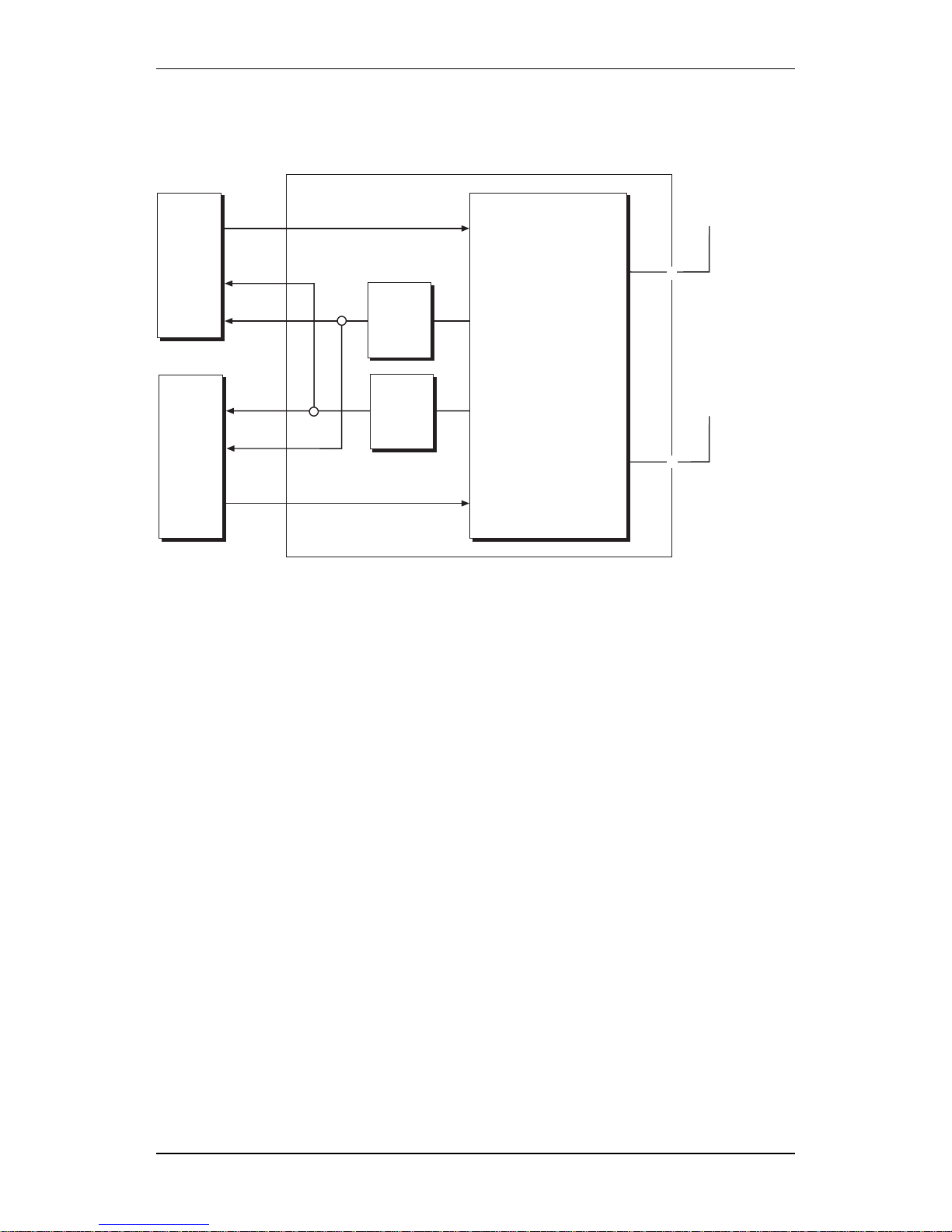
4.3 Configuration
4.3.1 Options
The RBS is a flexible product which can be ordered according to
different customer needs.
The following options are available:
• Mast mounting fixture
• Internal high precision oscillator
• Integral antennas
• Multicasting box
Multicasting functionality: One feeder system which can be used for a
distributed antenna system.
Sun-shield
The following optional colours are available for the front sun-shield.
NCS S3010-G80Y (Olive green)
NCS S2020-R70B (Sky blue)
NCS S2030-Y40R (Brick red)
NCS S2040-Y20R (Ochre)
NCS S1010-Y20R ( Light yellow)
According to NCS standard.
4.3.2 Variants
Configurations
The RBS will support the following basic configuration alternatives:
Table 5
GSM 900 GSM 1800 GSM 1900
M9d_1.2 M18d_1.2 M19d_1.2
M9d_2.2 M18d_2.2 M19d_2.2
The performance for each configuration is described in ref. /GS-Config/.
42 (306)
EN/LZT 123 2697 R5A
1998-08-13
© Ericsson Radio Systems AB
— All Rights Reserved —
Page 44

Product Specification for RBS 2301
02_0345A
CDU type
Frequency band
Duplexer
Number of antenna ports
Number of transcievers
M 9 d _ 2 . 2
Figure 21 How to read the code
Table 6
Object RBS Variants
Traffical capacity 2 TRX
Encryption A5/1, A5/2
Transport Network Interface 1.5 Mbit/s, 100 Ohm
2.0 Mbit/s, 75 Ohm
2.0 Mbit/s, 120 Ohm
Filter Duplex
Integral Antennas
The following selection are available: Omnidirectional or Sector.
4.4 Combinations
Possible combinations are described in Ordering Information.
EN/LZT 123 2697 R5A
1998-08-13
43 (306)
© Ericsson Radio Systems AB
— All Rights Reserved —
Page 45

Product Specification for RBS 2301
4.5 Transmission Modes
The RBS 2301 can be configured for linear cascade mode and stand
alone mode. The configuration is performed by means of the OMT.
When used as stand alone, PCM port A shall be connected towards the
BSC. In this mode, PCM port B cannot be used.
When used in linear cascade mode (multidrop), the RBSs are connected
so that each RBS uses its port A towards the BSC and port B towards
the next RBS. That RBS is connected in the same way with port A
towards the previous RBS (and indirectly the BSC) and port B towards
the next RBS etc.
Only RBSs that support multidrop can be included in the multidrop
chain. Figure 22 on page 44 shows a multidrop chain with three RBSs.
The multidrop function handles 64 kbit/s timeslots only. All RBSs have
dedicated timeslots.
BSC
01_0345A
Figure 22 Multidrop chain
44 (306)
EN/LZT 123 2697 R5A
1998-08-13
© Ericsson Radio Systems AB
— All Rights Reserved —
Page 46

Product Specification for RBS 2301
4.6 Interface and Connection
4.6.1 External Connections
AC Mains
Type of connections: Screw terminal for 4 X max.2.5 mm²
Cable gland capacity:
1 times Ø 14 mm
External Alarms
Type of connections: Screw terminal for 8 X max. 1.5 mm²
Cable gland capacity:
1 times Ø 10 mm
Number of alarms: 4
Antenna Connectors
Type of connectors: TNC (receptacle) female.
Note: When using integral antennas, Cables and connectors are
included, these connection are placed on the cabinet.
Transmission
Type of connections:
alternative
1. Coax Cable 75 Ohm
2. 100/120 Ohm
Earthing
Central earth terminal point M8 thread.
4.6.2 Internal Connections
OMT
Type of connections: 9 pin D-sub (receptacle) female.
4.6.3 Test Interface
The RBS is equipped with test ports for connection of external
instruments. The following signal are available at test ports:
13 MHz Reference
Type of connectors: SMB connector (receptacle) male.
EN/LZT 123 2697 R5A
1998-08-13
45 (306)
© Ericsson Radio Systems AB
— All Rights Reserved —
Page 47

Product Specification for RBS 2301
4.6.4 Operator Interface
When opening the Mounting Base there is an MMI area available
containing the operational interface which includes the LED’s and
buttons listed below.
Indicators (LEDs)
Fault One or more faults, equals BS fault.
Operational At least one TRX operational.
Local mode RBS in local mode.
Reduced capacity One of two TRX’s operational.
Test TRX1 Result from TRX1 test operation.
Test TRX2 Result from TRX2 test operation.
AC Power on AC Power is switched on to RBS.
Battery fault Lowbattery DC voltage, battery absent.
External alarm One or more external alarm active.
Buttons
CPU reset
Local/remote mode
Test Operation initiation
Switches
Battery
AC Mains
Barcodes Signs
The bar code sign for product identification is readable without
disturbing the RBS function.
4.7 Product Requirements
4.7.1 Appearance
Ericsson products are designed to appear as one physical unit,
inconspicuous, pleasant and good-looking. The standard colour of the
RBS is Grey.
The front cover of the RBS which is designed as a sun-shield may be
ordered in different colours to make the RBS even more inconspicuous.
There is an optional integrated antenna system which will support the
idea that the RBS and antenna site are the same.
46 (306)
EN/LZT 123 2697 R5A
1998-08-13
© Ericsson Radio Systems AB
— All Rights Reserved —
Page 48

Product Specification for RBS 2301
4.7.2 Mechanical Structure
Replaceable Units
The RBS consists of the following replaceable units:
• Cabinet
• Mounting base
• Integral antennas
• Sun-shield
• Batteries
• Connection unit
• Wall fixture
• Mast/pole fixture
Labels
All signs are placed to fulfil the requirements behind the purpose and
reason for the signs. And all signs that are needed for identification of
the product and its compliance are readable without disturbing the RBS
function.
4.7.3 Dimension and Weight
Volume
The total volume of a complete RBS site without cabling, 33 l.
Size
(HxWxD): 535x408x160 mm. (without integral antennas).
(HxWxD): 535x408x210 mm. (with Sector Antenna).
(HxWxD): 607x408x160 mm. (with Omnidirectional Antenna).
Weight
The total weight is the sum of the following handling units:
Cabinet 18 kg (incl. internal battery)
Mounting Base 6.5 kg (incl. Sun-shield)
Wall bracket 3 kg
Omni Antenna 0.5 kg
Sector Antenna 2 kg
Total Weight 30 kg
(A temporary lifting device can be attached during installation.)
EN/LZT 123 2697 R5A
1998-08-13
47 (306)
© Ericsson Radio Systems AB
— All Rights Reserved —
Page 49

Product Specification for RBS 2301
4.7.4 Hardware Characteristics
Acoustical Noise
The RBS will not contribute to the acoustical noise in the surroundings.
Vandal Resistance
The RBS will appear as vandal resistant and unauthorized intrusion will
not be possible without damaging the unit.
Package Material
The package material is recyclable.
Handling Robustness
The RBS main cabinet is designed to accept intermediate placing on the
ground during installation and maintenance work.
4.7.5 Environment
Operation
The RBS is designed to endure the requirement for “outdoor mast
mounted equipment”.
Temperature range:
-33
- +45C
For details see: Section "Environmental Capabilities RBS 2301"
Solar Radiation
The RBS is designed to withstand the additional heat from solar
radiation in it’s specified environment.
Transport
The RBS is designed to endure the requirement for transport.
Temperature range:
-40
C - +70C
For details see: Section "Environmental Capabilities RBS 2301"
Storage
The RBS is designed to endure the requirement for storage.
Temperature range:
-25
C - +55C
For details see: Section "Environmental Capabilities RBS 2301"
48 (306)
EN/LZT 123 2697 R5A
1998-08-13
© Ericsson Radio Systems AB
— All Rights Reserved —
Page 50

Product Specification for RBS 2301
Handling
The RBS is designed to endure the requirement for Handling. Handling
of RBS parts during installation and maintenance.
Temperature range:
-40
C - +70C
For details see: Section "Environmental Capabilities RBS 2301"
In addition to this requirement the RBS 2301 will endure topple. Minor
damages of the cabinet i.e. a broken corner of a cooling fin at topple
will not disturb the function of the RBS.
4.7.6 Climate Protection
Climate Protection Principle
The climate protection maintains the internal temperature within
allowed range for the units in the RBS.
The climate protection of the RBS is handled by a combination of:
• Natural convection with the help of cooling fins
• Conductional heating
Heating Capacity
The system have the capacity to heat the RBS from:
• −33
C to starting conditions within 30 minutes
• −15
C to starting conditions within 15 minutes
If the environmental conditions are: no wind or accumulated ice or
snow on the RBS.
Ingression
The RBS fulfil the IP-55 requirements according to the standard IEC
529.
4.7.7 Power Supply
Supply Voltage
The RBS can be connected to mains supply voltage with Nominal:
200 - 250 VAC ±10 % 50 Hz ±10 %
100 - 127 VAC ±10 % 60 Hz ± 8 %
200/100 - 240/120 ±10 % 60 Hz ± 8 %
The RBS will support installation with:
Single-phase (two-wire; earthed end of phase).
Single-phase (three-wire; earthed mid point).
EN/LZT 123 2697 R5A
1998-08-13
49 (306)
© Ericsson Radio Systems AB
— All Rights Reserved —
Page 51

Product Specification for RBS 2301
Single-phase (three-wire; separate PE and N conductor).
According to TN, TT and IT power system.
Power Consumption
Normal operation, both TRX’s
transmitting on full output power.
(at 230 V nominal mains supply)
150 VA
Maximum power consumption: 500 VA (only with activated heater).
Battery Backup
The RBS will survive interruptions on mains supply during at least 3
minutes. The RBS will maintain full performance during the backup
time if the battery is fully charged. The battery will be recharged to at
least 80% of its capacity within 15 hours.
For longer backup time an external UPS may be used.
4.7.8 Type Approval
Type Approval Standard
The product fulfils the required type approvals from: GSM 11.20 or
GSM 11.21 standard JTC standard FCC rules and regulations.
According to requirements in Section Product Safety Requirements RBS
2000.
4.7.9 Dependability
Preventive Maintenance
These preventive maintenance conditions must be fulfilled to guarantee
the availability of the RBS.
Action Interval
Change of battery < 5 years
Change of lightning protection equipment <10 years
Calibration of "optional" synchronisation oscillator < 3 years
50 (306)
EN/LZT 123 2697 R5A
1998-08-13
© Ericsson Radio Systems AB
— All Rights Reserved —
Page 52

Product Specification for RBS 2301
4.7.10 Installation
A quick and easy installation procedure is provided. If the installation
preconditions are met, the RBS can be installed in less than 30 minutes.
A minimum of tools and instruments are required when installing an
RBS.
Preconditions
•
The initiation of the BSC is prepared
• The transport network available
1)
at the site
• Mains power available at site
• Preinstalled antennas and feeders are available
1)
• Wall fixture preinstalled
• Friendly geographic location and environment (means higher than
-10
C, no precipitation and easy access to the site)
1)
"available" means: accessible and with specified function.
Installation Scenario
To support the idea of a quick and smooth installation scenario, the
RBS installation work can be divided in to two steps:
• Preinstallation. Installation of the Mounting Base, antennas and
all necessary cabling ( AC mains, transmission and alarms).
• Installation and Commissioning. Installation of the Cabinet
including all parts according to customer ordering.
However the installation is possible to carry out in one site visit.
The manual operations at installation are few and easy, this is valid also
when connecting external cables.
There is no need for an OMT on site, during installation work.
Site Installation Requirement
When installing more than one RBS at the same site, the RBS’s must
be separated. The separation is necessary because of antenna isolation
requirements and to provide sufficient working space.
EN/LZT 123 2697 R5A
1998-08-13
51 (306)
© Ericsson Radio Systems AB
— All Rights Reserved —
Page 53

Product Specification for RBS 2301
02_0330A
1000 mm
500mm
500 mm
500 mm
250 mm
500 mm
400 mm
Figure 23 Required separation between RBSs
• Min separation 0.5 m side by side
• Min separation 0.5 m above/below
• Min separation 0.4 m back to back
Free space is required around the RBS for installation and maintenance.
For a simple installation, following distances are recommended:
• Front: 1.0 m
• Side: 0.25 m
• Top: 0.5 m
• Bottom: 0.5 m
4.7.11 Production
The concept for the RBS supports production according to customer
choice from the ordering information plan.
52 (306)
EN/LZT 123 2697 R5A
1998-08-13
© Ericsson Radio Systems AB
— All Rights Reserved —
Page 54

Product Specification for RBS 2301
4.8 Future Expansion
4.8.1 Future Expansion Possibilities
• Datacommunication, i.e. 14.4 kbit/s and GPRS CS-2.
EN/LZT 123 2697 R5A
1998-08-13
53 (306)
© Ericsson Radio Systems AB
— All Rights Reserved —
Page 55

Product Specification for RBS 2301
This page is intentionally left blank
54 (306)
EN/LZT 123 2697 R5A
1998-08-13
© Ericsson Radio Systems AB
— All Rights Reserved —
Page 56

Product Specification for RBS 2302
5 Product Specification for RBS 2302
This chapter describes the architecture of the RBS 2302 and specifies its
the characteristics and performance.
5.1 Terminology
TN Power System TN Power System is a power distribution
system having one point directly earthed.
The exposed conductive parts of the
installation are connected to that point by
protective earth connectors.
TT Power System TT Power System is a power distribution
system having one point directly earthed.
The exposed conductive parts of the
installation are connected to earth
electrodes electrically independent of the
earth electrodes of the power system.
IT Power System IT Power System is a power distribution
system having no direct connection to
earth. The exposed conductive parts of the
electrical installation are earthed.
5.2 General
The RBS 2302 satisfies the need for ’hot spot’ capacity in small areas,
such as part of a city centre or a shopping mall, as well as ’fill in’
coverage.
The main focus with this product is to reduce site cost and make it
easier for operators to find sites, which will ensure operator profitability
of a micro cell network.
The RBS 2302 can be expanded with up to six transceivers by adding
extra RBS 2302 cabinet to a site.
To be able to support the idea of a small RBS that can be located
almost anywhere, some functional limitations has been made:
• No antenna supervision.
• No RF cable supervision.
The weather-proof cabinet and design make it ideal for installation
indoor, outdoor, on poles, walls or masts.
Integral antennas can be ordered as omni or sector antennas. Apart
from this there is always a possibility to connect external antennas.
A multicasting box is provided to make it possible to combine the
antenna signals from two TRXs into one antenna feeder.
For sites located in places with extreme heat an active cooling device
may be provided as an option.
An extended OMT port (a permanent cable from the RBS to a more
convenient place) is provided as an option.
EN/LZT 123 2697 R5A
1998-08-13
55 (306)
© Ericsson Radio Systems AB
— All Rights Reserved —
Page 57

Product Specification for RBS 2302
The base colour of the RBS is Grey (NCS S2502-R), but it is possible
to order the front sun-shields in different colours, which can make the
RBS more discrete depending on the environmental surroundings.
The RBS consists of the following main physical units: Mounting Base,
Cabinet, Antennas and Sun-shield. This will support a routine of
installing the Mounting Base prior to the Cabinet arrival.
P003472A
AC
AC
AC
Extended OMT cable
Transmission
Bus extension
Bus extension
Master
Cabinet
Extension
Cabinet
Extension
Cabinet
Figure 24 Six TRX site
The prime technical concerns have been to implement a RBS that:
• has a small size (volume and weight), and an appearance suitable
for a discrete installation ("landlord friendly").
• has high channel capacity, two transceivers giving total of 15
traffic channels if configured to one cell. The RBS 2302 may be
configured with up to six transceivers in one cell by adding extra
RBS 2302 as extension cabinets.
• is characterized by low need for preventive maintenance.
• has high MTBF
• has versions for the different system standards GSM 900, GSM
1800 and GSM 1900.
• includes all functions needed for a complete installation of a radio
base station, including standard interface G703 2048 kbit/s or DS1
1544 kbit/s to transmission network, AC mains power, battery
backup and a choice of internal or external antennas.
• supports Linear Cascade connection on the transmission interface.
• has an extended OMT-port that makes it possible for connection
of the OMT at ground level if the RBS 2302 is mounted high on
a wall or a pole.
• includes an optional fan-unit which extends the upper temperature
limit to +55 C
.
56 (306)
EN/LZT 123 2697 R5A
1998-08-13
© Ericsson Radio Systems AB
— All Rights Reserved —
Page 58

Product Specification for RBS 2302
• has space for a transmission module to support other transmission
protocols than G703 or DS1.
• can be installed by one person.
5.3 Product Architecture
5.3.1 Main Physical Units
Mountingbase
Sector antenna
omni radome/antenna
Interface box:
Interface board
Transmission filter board
Cabinet
Connection board
Installation
box
Sunshield
P003373A
Figure 25 Main Physical Units
EN/LZT 123 2697 R5A
1998-08-13
57 (306)
© Ericsson Radio Systems AB
— All Rights Reserved —
Page 59

Product Specification for RBS 2302
5.3.2 Hardware units
P003725A
PSU
TCB
LVF
DXB
TXU
TXU
FU
RXDA
DP
RXU
RXU
Figure 26 Hardware Units in the Cabinet
DXB Distribution Switching Board
The DXB (1 per RBS) is the central
control unit for the RBS and supports the
transmission interface.
OMT Operation and Maintenance Terminal
The OMT is a PC based terminal used
during installation and maintenance.
TCB Transceiver Control Board
The TCB (2 per RBS) includes equipment
related to signal processing for up to two
radio carriers.
TXU Transmitter Unit
The TXU (2 per RBS) contains equipment
for transmission on one radio carrier.
RXU Receiver Unit
The RXU (2 per RBS) contains equipment
for reception on one radio carrier.
RXDA Receiver Divider Amplifier
The RXDA (1 per RBS) contains
equipment for low noise amplification of
the received radio carrier(s) and dividing
each incoming RX into two output
carriers.
FU Filtering Unit
58 (306)
EN/LZT 123 2697 R5A
1998-08-13
© Ericsson Radio Systems AB
— All Rights Reserved —
Page 60

Product Specification for RBS 2302
The FU (1 per RBS) is the interface
between the transmitters, receivers and the
antenna system.
LVF Low Voltage Filter
The LVF contains components for voltage
filtering.
PSU Power Supply Unit
The PSU (1 per RBS), which rectifies the
incoming AC mains to regulated DC
voltages, controls and supervises the
battery and supervises the temperatures
inside the cabinet.
Climate Equipment Heater to heat the RBS at a low
temperature.
Battery The battery is an internal entity and is
replaceable without disturbing traffic
handling.
Connection Unit The connection unit contains components
for lightning and EMC protection. It also
includes fuses, AC mains and battery
switch as well as plinths for the external
interfaces except for antenna feeders.
Distribution Plane The distribution plane interfaces the DXB,
the TCB, the TXUs, the RXUs and the
PSU. It also contains the buttons and
indicators for the RBS.
5.4 Configurations
5.4.1 Options
Options are configurations that require additional hardware.
Appearance
The following optional colours are available for the front sun-shield
besides the standard colour.
NCS S2010-B70G (Olive green)
NCS S1020-R70B (Sky blue)
NCS S1020-Y90R (Brick red)
NCS S1020-Y50R (Brown)
NCS S1020-Y10R (Yellow)
According to NCS standard.
EN/LZT 123 2697 R5A
1998-08-13
59 (306)
© Ericsson Radio Systems AB
— All Rights Reserved —
Page 61

Product Specification for RBS 2302
5.4.2 Variants
Radio Configurations
The RBS will support the following basic configuration alternatives:
Table 7
GSM 900 GSM 1800 GSM 1900
M9d_2.2 M18d_2.2 M19d_2.2
The performance for each configuration is described in chapter Radio
Configurations, RBS 2000 Micro.
02_0345A
CDU type
Frequency band
Duplexer
Number of antenna ports
Number of transcievers
M 9 d _ 2 . 2
Figure 27 How to read the code
Table 8
Object RBS Variants
Traffic capacity 2 TRX
Encryption A5/1, A5/2
Transport Network Interface 1.5 Mbit/s, 100 Ohm
2.0 Mbit/s, 75 Ohm
2.0 Mbit/s, 120 Ohm
Filter Duplex
It is possible to equip the RBS with either external antennas, integral
antennas or an active antenna system (MAXITE
TM
).
Using the active antenna, the RBS supports a “highway configuration”,
where two TRXs cover two directions as one cell, as specified below.
It is also possible to extend one cabinet with up to two other cabinets to
form a 4 or 6 TRX site.
The RBS supports a multicasting box, as specified below.
The RBS 2302 will support the following basic configuration
alternatives:
60 (306)
EN/LZT 123 2697 R5A
1998-08-13
© Ericsson Radio Systems AB
— All Rights Reserved —
Page 62

Product Specification for RBS 2302
Table 9
GSM 900 GSM 1800 GSM 1900
M9d_1.2 M18d_1.2 M19d_1.2
M18d_2.2\H M19d_2.2\H
M18d_2.2\A M19d_2.2\A
M9d_4.4 M18d_4.4 M19d_4.4
M18d_4.4\A M19d_4.4\A
M9d_6.6 M18d_6.6 M19d_6.6
M18d_6.6\A M19d_6.6\A
Integral Antennas
The following sections are available: Omni Antenna or Sector Antenna.
External Passive Antennas
The RBS supports the use of customer specific external antennas.
Multicasting box
It is possible to connect a multicasting box to the antenna connectors
that combine the antenna signals from each TRX to one antenna feeder.
The multicasting box is only supported for 2 TRX configurations.
Transmission
It is possible to change the door on the installation box to a wider door
with a modem to support HDSL, ISDN or some other protocol.
Extended temperature range
It is possible to extend the temperature range by +10 Cusing a fan
unit, placed on top of the RBS.
Extended OMT interfaces
The RBS supports a permanent extension of the OMT-port. The
extension cable length may be up to 50 m. The PC end of the extension
is designed for outdoor weather protected locations.
External battery backup
The RBS supports an external battery backup (the PBC) source using an
adapter, mounted in the battery compartment of the RBS. The backup
voltage requirements are further specified in chapter Product
Specification for Power and Battery Cabinet.
EN/LZT 123 2697 R5A
1998-08-13
61 (306)
© Ericsson Radio Systems AB
— All Rights Reserved —
Page 63

Product Specification for RBS 2302
5.4.3 Variants
Enhanced Lightning Protection
To protect the RBS 2302 from lightening it is possible to order an
Enhanced Lightning Protection.
5.4.4 On Site Configurable Options and Variants
On site configurable options and variants are configurations that do not
require different or additional hardware, see chapter RBS 2000 Micro,
Site Configurations for more details.
5.5 Combinations
Possible combinations are described in Ordering Information.
5.6 Transmission Modes
Transmission
The RBS 2302 can be configured for linear cascade mode and stand
alone mode. The configuration is performed by means of the OMT.
When used in stand alone mode, PCM port A is connected to the BSC.
In this mode, PCM port B cannot be used.
When used in linear cascade mode (multidrop), the RBSs are connected
so that the first RBS uses its port A towards the BSC and port B
towards the second RBS. The consecutive RBSs are connected in the
same way with port A towards the previous RBS (and indirectly the
BSC) and port B towards the next RBS etc.
The transmission functionality is further specified in relevant function
specifications, see chapter Transmission and Interface Handling G.703
2048 kbit/s and Transmission and Interface Handling DS1 1544 kbit/s.
62 (306)
EN/LZT 123 2697 R5A
1998-08-13
© Ericsson Radio Systems AB
— All Rights Reserved —
Page 64

Product Specification for RBS 2302
BSC
01_0345A
Figure 28 Multidrop chain
5.7 Interface and Connection
5.7.1 External Connections
AC Mains
Type of connections: Screw terminal for 4 X max.2.5 mm²
Cable gland capacity:
1 times Ø8-19mm
External Battery Backup
Type of connections: The adapter must fit the battery
compartment of the RBS.
External Alarms
Type of connections: Screw terminal for 16 x max. 1.5 mm²
Cable gland capacity:
2 x Ø5-9 mm
Number of alarms: 8
Antenna Connectors
Type of connectors: 2 x TNC (receptacle) female.
EN/LZT 123 2697 R5A
1998-08-13
63 (306)
© Ericsson Radio Systems AB
— All Rights Reserved —
Page 65

Product Specification for RBS 2302
Note: When using integral antennas, cables and connectors are
included. These connection are placed on the cabinet.
Transmission
Twisted pair:
Type of connections: Screw terminal for 12 x max. 1.5 mm
2
Cable gland capacity:
2 x Ø7-15 mm
Coaxial:
Type of connection: 4 x TNC (receptacle) female
Grounding: The transmit wire screen is grounded. It is
possible to ground the receive wire screen.
Earthing
Type of connectors: Central earth terminal point M8 thread
5.7.2 Internal Connections
OMT
Type of connections: 9 pin D-sub (receptacle) female.
Extended OMT-port
Type of connections: 9 pin D-sub female.
Maximum cable length: 50 m
Cable gland capacity:
1 x Ø5-9 mm
5.7.3 Test Interface
The RBS is equipped with test ports for connection of external
instruments. The following signals are available at test ports:
13 MHz Reference
Type of connectors: SMB connector (receptacle) male.
RTS-PLS Test Port
Type of connectors: No requirements
5.7.4 Operator Interface
The operator interface is located in the Mounting Base. The interface
includes indicators and buttons, switches and barcode signs. For exact
specification of button and indicator functionality see chapter Operation
& Maintenance Support.
64 (306)
EN/LZT 123 2697 R5A
1998-08-13
© Ericsson Radio Systems AB
— All Rights Reserved —
Page 66

Product Specification for RBS 2302
Indicators (LEDs)
Fault One or more faults, equals BS fault.
Operational At least one TRX operational.
Local mode RBS in local mode.
Reduced capacity One of two TRXs operational.
Test TRX1 Result from TRX1 test operation.
Test TRX2 Result from TRX2 test operation.
AC Power on AC Power is switched on to RBS.
Battery fault Lowbattery DC voltage, battery absent.
External alarm One or more external alarm active.
Buttons
CPU reset
Local/remote mode
Test Operation
initiation
Switches
Battery connected/not connected
AC Mains connected/not connected
Barcode Sign
The barcode sign for product identification is readable without disturbing
the RBS function.
5.8 Product Requirements
5.8.1 Appearance
Ericsson products are designed to appear as one physical unit,
inconspicuous, pleasant and good-looking. The standard colour of the
RBS is Grey.
The front cover of the RBS which is designed as a sun-shield is
available in different colours to make the RBS even more inconspicuous.
There is an optional integrated antenna system which supports the idea
of the RBS and the antenna site as one unit.
5.8.2 Mechanical Structure
Replaceable Units
The RBS consists of the following replaceable units:
• Cabinet
EN/LZT 123 2697 R5A
1998-08-13
65 (306)
© Ericsson Radio Systems AB
— All Rights Reserved —
Page 67

Product Specification for RBS 2302
• Mounting base
• Installation box door
• Integral antennas
• Sun-shield
• Batteries
• AC-filter board (including overvoltage protection)
• Transmission filter board (including overvoltage protection)
• Wall bracket
• Mast/pole fixture
• Connection board
Labels
All signs are placed to fulfil the requirements behind the purpose and
reason for the signs. And all signs that are needed for identification of
the product and its compliance are readable without disturbing the RBS
function.
Locks
The installation box door is equipped with a lock which can be
exchanged if neccesary.
5.8.3 Dimension and Weight
Volume
The total volume of a complete RBS site without cabling, is less than
35 l.
Size
(HxWxD): 535x408x160 mm. (without integral antennas).
(HxWxD): 535x408x210 mm. (with Sector Antenna).
(HxWxD): 607x408x160 mm. (with Omnidirectional Antenna).
Weight
The total weight is the sum of the following units:
Cabinet 18 kg (incl. Internal battery)
Mounting Base 8 kg (incl. Sun-shield)
Wall bracket 5 kg (incl. Pole fixture)
Total weight 31 kg
66 (306)
EN/LZT 123 2697 R5A
1998-08-13
© Ericsson Radio Systems AB
— All Rights Reserved —
Page 68

Product Specification for RBS 2302
5.8.4 Hardware Characteristics
Acoustical Noise
The RBS will not contribute to the acoustic noise in the surroundings.
The optional fan-unit contributes with less than 5.5 Bel at temperatures
below +30 C
and less than 6.5 at all other temperature.
Vandal Resistance
The RBS is designed as vandal resistant and unauthorized intrusion will
not be possible without damaging the unit.
Package Material
The package material is recyclable.
Handling Robustness
The RBS main cabinet is designed to be placed on the ground during
installation and maintenance work.
5.8.5 Environment
Operation
The RBS meets the following requirement for “outdoor mast mounted
equipment”.
Temperature range:
-33
to +45C
-33
to +55C (with fan-unit)
Solar Radiation
The RBS is designed to withstand the additional heat from solar
radiation in its specified environment.
Transport
The RBS meets the following transport requirements.
Temperature range:
-40
C to +70C
Storage
The RBS is designed to endure the requirement for storage.
Temperature range:
-25
C to +55C
Handling
The RBS is designed to endure the requirement for Handling.
EN/LZT 123 2697 R5A
1998-08-13
67 (306)
© Ericsson Radio Systems AB
— All Rights Reserved —
Page 69

Product Specification for RBS 2302
Temperature range:
-40
C to +70C
In addition to this requirement the RBS 2302 can be toppled without
damage. Minor damage to the cabinet that is a broken corner of a
cooling fin after a topple will not disturb the function of the RBS.
5.8.6 Climate Protection
Climate Protection Principle
The climate protection maintains the internal temperature within the
allowed range for the units in the RBS.
The climate protection of the RBS is handled by a combination of:
• Natural convection with the help of cooling fins
• Conductional heating
The fan-unit increases the air flow over the cooling fins.
Heating Capacity
The system has the capacity to heat the RBS from:
• −33
C to starting conditions within 30 minutes
• −15
C to starting conditions within 15 minutes
The above only applies if the environmental conditions are: no wind or
accumulated ice or snow on the RBS.
Ingression
The RBS fulfils the IP-55 requirements according to the standard IEC
529 and type 3R according to UL50.
5.8.7 Power Supply
Supply Voltage
The RBS can be connected to mains supply voltage with Nominal:
200 - 250 VAC ±10 % 50 Hz ±10 %
100 - 127 VAC ±10 % 60 Hz ± 8 %
200/100 - 240/120 ±10 % 60 Hz ± 8 %
The RBS will support installation with:
Single-phase (two-wire; earthed end of phase).
Single-phase (three-wire; earthed mid point).
Single-phase (three-wire; separate PE and N conductor).
According to TN, TT and IT power system.
The AC supply is fused.
68 (306)
EN/LZT 123 2697 R5A
1998-08-13
© Ericsson Radio Systems AB
— All Rights Reserved —
Page 70

Product Specification for RBS 2302
Power Consumption
Normal operation, both TRXs transmitting on full
output power (at 230 V nominal mains supply):
<140 VA
Maximum power consumption: <500 VA (only with
activated heater).
The optional fan-unit (at 230 V nominal mains
supply):
<15 VA
Battery Backup
The RBS will survive interruptions on mains supply for at least 3
minutes. The RBS will maintain full performance during the backup
time if the battery is fully charged. The battery will be recharged to at
least 80% of its capacity within 15 hours.
For longer backup time an external UPS or PBC may be used.
Battery Backup (PBC)
The Battery Backup Time is further specified in chapter Site
Configuration, RBS 2000 Micro.
5.8.8 Type Approval
Type Approval Standard
The RBS 2302 fulfils the required type approvals from: GSM 11.20 or
GSM 11.21 standard JTC standard FCC rules and regulations.
According to requirements in Section Product Safety Requirements RBS
2000.
Product Safety
The RBS 2302, 1900 MHz is listed by the National Recognized Testing
Laboratory (NRTL).
EMC
The RBS complies with the European Community market requirements
regarding EMC for Base station equipment. The product has the CE
sign to show this compliance.
The RBS complies with the US market requirement regarding EMC for
Base station equipment. The product has the FCC sign to show this
compliance.
The RBS fulfils the electromagnetic requirements for Base station Radio
meeting Phase 2 GSM requirements according to ETS 300 342–3.
EN/LZT 123 2697 R5A
1998-08-13
69 (306)
© Ericsson Radio Systems AB
— All Rights Reserved —
Page 71

Product Specification for RBS 2302
5.8.9 Dependability
Technical Lifetime
The RBS is designed for a technical lifetime of 20 years (24 hours
operation).
Preventive Maintenance
The RBS has the following availability performance.
Action Interval
Mean repair time (MRT) < 60 minutes
Mean time between failures (MTBF) <8.5 years
Mean accumulated down time (MADT) <6 minutes/year (time to reach
the site is not included)
These preventive maintenance conditions must be fulfilled to guarantee
the availability figures above.
Action Interval
Change of battery < 5 years
Change of lightning protection equipment <10 years
Calibration of "optional" synchronisation oscillator < 3 years
5.8.10 Installation
A quick and easy installation procedure is provided. If the installation
preconditions are met, the RBS can be installed in less than 30 minutes.
A minimum of tools and instruments are required when installing an
RBS.
Preconditions
•
It is possible to adjust the RBS in vertical direction ± 10.
• Wall mounting with no visible cables is supported.
• The initiation of the BSC is prepared.
• The transport network is available
1)
at the site
• Mains power is available at site
• Preinstalled antennas and feeders are available
1)
• Wall fixture is preinstalled
• Favourable geographic location and environment (means higher
than -10
C, no precipitation and easy access to the site)
1)
"available" means: accessible and with specified function.
70 (306)
EN/LZT 123 2697 R5A
1998-08-13
© Ericsson Radio Systems AB
— All Rights Reserved —
Page 72

Product Specification for RBS 2302
Installation Scenario
To support the concept of a quick and smooth installation scenario, the
RBS installation work can be divided in to two steps:
• Preinstallation. Installation of the Mounting Base, antennas and
all necessary cabling ( AC mains, transmission and alarms).
• Installation and Commissioning. Installation of the Cabinet
including all parts according to customer ordering.
However, the installation can be performed in one site visit.
The manual operations at installation are few and easy, this is valid also
when connecting external cables.
Site Installation Requirement
Free space is required around the RBS for installation and maintenance.
For a simple installation, the following distances are recommended:
• Front: 1.0 m
• Side: 0.25 m
• Top: 0.5 m
• Bottom: 0.5 m
For 4 and 6 TRX, the maximum distance between the cabinets is 5 m,
which is the length of the cable.
If external battery backup is used, the following distances are required:
• Top: 0.7 m
• Bottom: 0.7 m
5.8.11 Production
The concept for the RBS supports production according to customer
choice from the ordering information plan.
5.9 Future Expansion
5.9.1 Future Expansion Possibilities
• The hardware of the RBS is prepared for the expansion of up to 4
and 6 TRX.
EN/LZT 123 2697 R5A
1998-08-13
71 (306)
© Ericsson Radio Systems AB
— All Rights Reserved —
Page 73

Product Specification for RBS 2302
This page is intentionally left blank
72 (306)
EN/LZT 123 2697 R5A
1998-08-13
© Ericsson Radio Systems AB
— All Rights Reserved —
Page 74

Product Specification for Power and Battery Cabinet
6 Product Specification for
Power and Battery Cabinet
This chapter describes the architecture of the Power and Battery Cabinet
(PBC), and specifies its characteristics and performance.
6.1 Terminology
TN Power System TN Power System is a power distribution
system having one point directly earthed .
The exposed conductive parts of the
installation are connected to that point by
protective earth connectors.
TT Power System TT Power System is a power distribution
system having one point directly earthed .
The exposed conductive parts of the
installation are connected to earth
electrodes electrically independent of the
earth electrodes of the power system.
IT Power System IT Power System is a power distribution
system having no direct connection to
earth. The exposed conductive parts of the
electrical installation are earthed.
Link Equipment Link Equipment is used to establish
contact with the BSC if there is no fixed
network between the RBS and the BSC.
Second PBC A second PBC is used in configurations
which require two AAUs connected to one
RBS.
Replaceable Unit In this document Replaceable Unit refers
to units that are replaceable on site.
6.2 General
The PBC serves as a common base for battery back-up and power
supply to the Active Antenna, the micro RBS and optional transmission
equipment (link equipment). The PBC is also an interface for alarms
from the Active Antenna and the RBS.
After a complete discharge of the battery the recharging time is less
than 24 hours.
In order to reuse already developed parts the mechanical outline is
similar to Ericssons micro basestation family. The units are based on
modular, standardized assembly structure.
Easy access of the batteries for maintenance without disturbing the
traffic.
The weather-proof cabinet and design make it ideal for installation
indoor, outdoor, on poles, walls or masts.
EN/LZT 123 2697 R5A
1998-08-13
73 (306)
© Ericsson Radio Systems AB
— All Rights Reserved —
Page 75

Product Specification for Power and Battery Cabinet
The base colour of the PBC is Grey, but it is possible to order the front
sun-shields in different colours, which can make the PBC more discrete
depending on the environmental surroundings.
The PBC is built up by the following main physical units: Battery
Cabinet, Sun-shields, Lid and Mounting Base where Installation Box
and Interface Box are included. This will support a routine of installing
the Mounting Base prior to the Cabinet arrival.
The PBC has the same width and length as the micro RBS but the rear
sun-shield is modified to achieve the additional volume needed to fit the
batteries.
6.3 Product Architecture
6.3.1 Main Physical Units
P003439A
Front sunshield
Upper sunshield
Left sunshield
Lower sunshield
Mounting base
Battery
Cabinet
Interface box
Installation box
Figure 29 Main Physical Units
BC Battery Cabinet
The BC contains a AC/DC converter and
batteries for DC-backup. The batteries are
replaceable without disturbing traffic
handling.
Installation Box The Installation Box contains the
MMI-area.
Interface Box The Interface Box contains all ports to
external equipment as follows:
74 (306)
EN/LZT 123 2697 R5A
1998-08-13
© Ericsson Radio Systems AB
— All Rights Reserved —
Page 76

Product Specification for Power and Battery Cabinet
AC Mains to PBC
–48 V to link equipment
–48 V and Data to AAU in the same port
two ports 24 V to RBS
alarm port from second PBC
binary alarms to the RBS
The Interface Box also contains surge
protection devices on all external
terminals. The internal interface is
designed so that it is possible to remove
the surge protection devices and install an
optional reinforced surge device.
Mounting Base The Mounting Base serves as a base for
the Battery Cabinet.
Sun-shield The Sun-shields protect the PBC from
sun, wind, rain and snow.
6.4 Configurations
6.4.1 Options
Options are configurations that require additional hardware.
Appearance
The following optional colours are available for the sun-shields besides
the standard colour.
NCS S2010-B70G (Olive green)
NCS S1020-R70B (Sky blue)
NCS S1020-Y90R (Brick red)
NCS S1020-Y50R (Brown)
NCS S1020-Y10R (Yellow)
According to NCS standard.
6.4.2 Variants
Enhanced Lightning Protection
To protect the PBC from lightening it is possible to order an Enhanced
Lightning Protection.
EN/LZT 123 2697 R5A
1998-08-13
75 (306)
© Ericsson Radio Systems AB
— All Rights Reserved —
Page 77

Product Specification for Power and Battery Cabinet
6.4.3 On Site Configurable Options and Variants
On site configurable options and variants are configurations that do not
require different or additional hardware, see chapter RBS 2000 Micro,
Site Configurations for more details.
6.5 Combinations
Possible combinations are described in Ordering Information.
6.6 Interface and Connection
6.6.1 External Connections
AC Mains
Type of connections: Screw terminal for 3 x max.2.5 mm²
Cable gland capacity:
1 times Ø 10.5-14 mm
Data/DC port
Type of connections: Data and -48 V
Cable gland capacity:
1 times ∅ 14-16 mm
Data
Type of connections: Screw terminal for 2 x max. 0.6 mm²
Cable gland capacity: See Data/DC port
Earthing
Type of connectors: Central earth terminal point M8 thread
Binary Alarms
The PBC has eight alarm terminals. Four of them are used to connect
the RBS. The remaining four terminals are used to connect the external
alarms from the second PBC.
76 (306)
EN/LZT 123 2697 R5A
1998-08-13
© Ericsson Radio Systems AB
— All Rights Reserved —
Page 78

Product Specification for Power and Battery Cabinet
PBC Alarms to RBS
Type of connections: Screw terminal for 4 x 2x max.1.5 mm²
Cable gland capacity:
1 times Ø 7.5-9.5 mm
Number of alarms: 4
PBC Alarms from
second PBC
Type of connections: Screw terminal for 4 x 2x max.1.5 mm²
Cable gland capacity:
1 times Ø 7.5-9.5 mm
Number of alarms: 4
+24 Volt DC
The PBC supplies two regulated DC voltages with +24 V. The two
voltages are fused separately.
Each voltage supplies the RBS with DC power. The voltages are
galvanically isolated from -48 V and from Cassie/ground.
+24 V, RBS 1
Type of connections: Screw terminal for 2x max.1.5 mm²
Cable gland capacity:
1 times Ø 7.5-9.5 mm
+24 V, RBS 2
Type of connections: Screw terminal for 2x max.1.5 mm²
Cable gland capacity:
1 times Ø 7.5-9.5 mm
–48 Volt DC
The PBC supplies two regulated DC voltages with -48 V. The two
voltages are fused separately. One voltage supplies the AAU and the
other voltage supplies the Link equipment.
The two voltages are positive grounded, that is the terminal with the
highest potential is connected to Cassie/ground. The voltages are not
galvanically isolated from each other.
-48 V, AAU
Type of connections: Screw terminal for 2x max. 6 mm²
Cable gland capacity: See Data/DC port
-48 V, Link Equipment
Type of connections: Screw terminal for 2x max. 2.5 mm²
Cable gland capacity:
1 times ∅ 7.5-9.5 mm
EN/LZT 123 2697 R5A
1998-08-13
77 (306)
© Ericsson Radio Systems AB
— All Rights Reserved —
Page 79

Product Specification for Power and Battery Cabinet
6.6.2 Operator Interface
When opening the Lid to the Installation Box there is an MMI area
available containing the operational interface which includes two LEDs,
three 7–segment indicators and a number of buttons, see fig below.
OPERATIONAL FAULT
P003220A
Up
Down
Menu
Enter
I
O
Batt
Power
D1 D2 D3
Figure 30 MMI Interface
Indicators (LEDs)
Colours
-Green Operational
-Green and red Warning
-Red Fault
Display
Display 1 Unit number
Display 2 Alarm severity
Display 3 Error code
Buttons
Up Step numbers up on the display
Down Step numbers down on the display
Menu Select between display elements
Enter Transfers commands to AAU
Barcode Sign
The barcode sign for product identification is readable without disturbing
the PBC function.
78 (306)
EN/LZT 123 2697 R5A
1998-08-13
© Ericsson Radio Systems AB
— All Rights Reserved —
Page 80

Product Specification for Power and Battery Cabinet
6.7 Product Requirements
6.7.1 Functional Requirements
MMI Handling
The PBC MMI functions provides the following:
• Supervision of the Antenna alarm signals
• Communication link between the AAU and the PBC
• Supervision of the PBC alarm signals
• Alarm signalling to the RBS
• User interface for installation settings and alarm presentation
Codes on display
Display 1 (D1) shows the unit number as follows:
0 = PBC
1 = Antenna part 1
2 = Antenna part 2
3 = Antenna part 3
4=
5 = Feeder A
6 = Feeder B
7 = Installation faults
Antenna part 2 and 3 are used if the antenna consists of more than
one unit.
Display 2 (D2) shows the severity of an alarm as follows:
0 = Not Classified
1 = Severe
2= Warning
The messages for the feeder values also use this element, see below.
Display 3 (D3) shows which type of error has occured or the command that
is transmitted to the AAU as follows:
0 = AC fault
1 = AC/DC fault
2 = DC/DC overload
3 = DC/DC fault
4 = Battery fault
EN/LZT 123 2697 R5A
1998-08-13
79 (306)
© Ericsson Radio Systems AB
— All Rights Reserved —
Page 81

Product Specification for Power and Battery Cabinet
5 = Battery disconnected
6 = Low battery voltage
7 = Overtemp, active
8 = Overtemp, historical
9 = Mode fault in PBC
AAU:
0 = Transmission fail
1 = DC fault
2 = TXA fault
3 = TXB fault
4 = RXA fault
5 = RXB fault
6 = Overtemp, active
7 = Overtemp, historical
P = Output power off
H = FDU attenuators set to max
Feeder:
0-12= Cable attenuation value
The attenuation value is allowed to be between 0 and 12, presented
in one dB-steps (integers only).
Installation:
1 = Feeder A, installation fault
2 = Feeder B, installation fault
Note: The alarms Installation fault, Output power off, and FDU
attenuators set to max are only used during installation.
Operator Control Buttons
The buttons are used together with the display to initiate the feeder
cable attenuation setting and to step through the error codes.
If an alarm error code is received it is immediately shown on the
display. If there are several errors, the operator is able to step through
the error codes with the UP/DOWN buttons.
All errors displayed are current alarms, that is no history is displayed on
the MMI. The temperature alarms are however handled in another way
because they are differentiated as active or historical.
80 (306)
EN/LZT 123 2697 R5A
1998-08-13
© Ericsson Radio Systems AB
— All Rights Reserved —
Page 82

Product Specification for Power and Battery Cabinet
6.7.2 Alarm Description
Internal Alarm in the PBC
AC fault
Raise condition: Activated if AC mains is below 85 V
Cease condition: Activated if AC mains is more than
88 V
Alarm severity: Warning
Action: None
AC/DC fault
Raise condition: Activated if output voltage from
PSU is less than 45 V
Cease condition: The normal voltage has returned
Alarm severity: Warning
Action: None
DC/DC overload
Raise condition: Activated if one of the two 24 V
outputs are overloaded, for example,
the current is outside specified value.
Cease condition: The load must be disconnected and
the current must be within specified
values.
Alarm severity: Warning
Action: None
DC/DC fault
Raise condition: Activated with low output voltage or
high temprature in DC/DC &
Supervisor.
Cease condition: The normal voltage and the
temperature has returned.
Alarm severity: Warning
Action: None
Battery fault
Raise condition: Activated if the battery is faulty or if
charging is not operating normally.
Cease condition: Correct battery or normal charging
has returned.
EN/LZT 123 2697 R5A
1998-08-13
81 (306)
© Ericsson Radio Systems AB
— All Rights Reserved —
Page 83

Product Specification for Power and Battery Cabinet
Alarm severity: Warning
Action: None
Battery disconnected
Raise condition: Activated if the battery is not
connected to the battery switches.
Cease condition: The battery is connected.
Alarm severity: Warning
Action: Connect the battery switches.
Low battery voltage
Raise condition: Activated if the battery voltage is
less than 43.5 V.
Cease condition: When the battery voltage is more
than 43.5 V.
Alarm severity: Warning
Action: None
Overtemperature, active
Raise condition: OvertempErature in the PSU, the
battery unit or the DC/DC
supervisor.
Cease condition: When the internal tempErature has
returned.
Alarm severity: Warning
Action: None
Overtemperature, historical
Raise condition: Overtemperature in the PSU, the
battery unit or the DC/DC
supervisor.
Cease condition: Manual reset
Alarm severity: Warning
Action: None
The PBC internal alarms are mapped to the following binary alarms:
SEVERE_A AAU, carrier A, severe
SEVERE_B AAU, carrier B, severe
WARNING AAU, carrier A or B, warning
POWER PBC, any error, warning
82 (306)
EN/LZT 123 2697 R5A
1998-08-13
© Ericsson Radio Systems AB
— All Rights Reserved —
Page 84

Product Specification for Power and Battery Cabinet
6.7.3 Appearance
Ericsson products are designed to appear as one physical unit,
inconspicuous, pleasant and good-looking. The standard colour of the
RBS is Grey.
The front cover of the PBC which is designed as a sun-shield may be
ordered in different colours to make the PBC even more discrete.
6.7.4 Mechanical Structure
Replaceable Units
The PBC consists of the following replaceable units:
• Battery Cabinet
• Mounting base
• Installation box cover
• Interface box
• Sun-shields
• Batteries
• Mounting plate
• Mast/pole fixture
• Lightning protection unit
• Protection Cover
Labels
All signs are placed to fulfil the requirements behind the purpose and
reason for the signs. All signs that are needed for identification of the
product and its compliance are readable without disturbing the PBC
function.
6.7.5 Dimension and Weight
Volume
The total volume of a complete PBC site without cabling, is less than
56 l.
Size
(HxWxD): 535 x 408 x 330 mm.
EN/LZT 123 2697 R5A
1998-08-13
83 (306)
© Ericsson Radio Systems AB
— All Rights Reserved —
Page 85

Product Specification for Power and Battery Cabinet
Weight
Battery Cabinet 23 kg
Batteries 21 kg
Mounting Base 9.5 kg
Mounting Plate 3.0 kg
Sunshields 1.5 kg
Total weight 58 kg
6.7.6 Hardware Characteristics
Acoustic Noise
The PBC will not contribute to the acoustic noise in the surroundings.
Vandal Resistance
The PBC is designed to be vandal resistant and unauthorized intrusion
will not be possible without damaging the unit.
Package Material
The package material is recyclable.
Handling Robustness
The PBC main cabinet is designed to accept intermediate placing on the
ground during installation and maintenance work.
6.7.7 Environment
Operation
The PBC is designed to endure the requirement for Outdoor Mast
Mounted Equipment.
Temperature range:
-33
- +45C
Operating at battery backup:
-10
- +45C
Solar Radiation
The PBC is designed to withstand the additional heat from solar
radiation in its specified environment.
Transport
The PBC meets the following transport requirement.
84 (306)
EN/LZT 123 2697 R5A
1998-08-13
© Ericsson Radio Systems AB
— All Rights Reserved —
Page 86

Product Specification for Power and Battery Cabinet
Temperature range:
-40
C - +70C
Storage
The PBC meets the following storage requirement.
Temperature range:
-25
C - +55C
Handling
Temperature range:
-40
C - +70C
The PBC is designed to be placed on the ground.
In addition to this requirement the PBC will endure a topple. Minor
damages to the cabinet, for example a broken corner of a cooling fin
after a topple, will not disturb the function of the PBC.
6.7.8 Climate Protection
Climate Protection Principle
The climate protection maintains the internal temperature within
allowed range for the units in the PBC.
The climate protection of the PBC is handled by a combination of:
• Natural convection using cooling fins
• Conductional heating
Battery Heating Capacity
The system delivers DC to the external users independent of
temperature.
The system has the capacity to heat the batteries from −33
C to start
charging within 30 minutes (15 minutes from −15
C) if the
environmental conditions are no wind.
The above applies if the environmental conditions are: no wind or
accumulated ice or snow on the PBC.
During back-up mode the heater is not operational.
Ingression
The PBC fulfils the IP-55 requirements according to the standard IEC
529 and type 3R according to UL50.
6.7.9 Power Supply
Input Supply Voltage
The PBC can be connected to mains supply voltage with Nominal:
EN/LZT 123 2697 R5A
1998-08-13
85 (306)
© Ericsson Radio Systems AB
— All Rights Reserved —
Page 87

Product Specification for Power and Battery Cabinet
200 - 250 VAC ±10 % 50 Hz ±10 %
100 - 127 VAC ±10 % 60 Hz ± 8 %
200/100 - 240/120 ±10 % 60 Hz ± 8 %
The PBC will support installation with:
Single-phase (two-wire; earthed end of phase).
Single-phase (three-wire; earthed mid point).
Single-phase (three-wire; separate PE and N conductor).
according to TN, TT and IT power system
Output Supply Voltage
The PBC delivers the following output voltages:
RBS
Nominal + 24 V range 21.5-28 V
Nominal load current 5.2 A
AAU
Nominal -54.1 V range -42.8- -60V
Nominal load current 4.0 A
Link
Nominal -54.1 V range -42.8- -60V
Nominal load current 0.6 A
Power Consumption
Regarding Power Consumption figures see chapter General
Specification for RBS 2000 Micro Site Configuration.
Battery Backup
The PBC battery backup time is between 1.5–3 hours depending on
which configuration is used. The battery will be recharged within 24
hours.
For longer backup time an external UPS may be used.
6.7.10 Type Approval
Type Approval Standard
The PBC fulfils the required type approvals from: GSM 11.20 or GSM
11.21 standard JTC standard FCC rules and regulations. According to
requirements in Section Product Safety Requirements RBS 2000.
86 (306)
EN/LZT 123 2697 R5A
1998-08-13
© Ericsson Radio Systems AB
— All Rights Reserved —
Page 88

Product Specification for Power and Battery Cabinet
Product Safety
The PBC is listed by the National Recognized Testing Laboratory
(NRTL).
EMC
The PBC complies with the European Community market requirements
regarding EMC for Base station equipment. The product has the CE
sign to show this compliance.
The PBC complies with the US market requirement regarding EMC for
Base station equipment. The product has the FCC sign to show this
compliance.
The PBC fulfils the electromagnetic requirements for Base station Radio
meeting Phase 2 GSM requirements according to ETS 300 342–3.
6.7.11 Dependability
Technical Lifetime
The PBC is designed for a technical lifetime of 20 years (24 hours
operation).
Preventive Maintenance
The PBC has the following availability performance.
Action Interval
Mean repair time (MRT) < 30 minutes
Mean time between failures (MTBF) <28 years
Mean accumulated down time (MADT) <1 minutes/year (time to reach
the site is not included)
These preventive maintenance conditions must be fulfilled to guarantee
the availability figures above.
Action Interval
Change of battery < 10 years (with an
annual temperature
of +20
C)
Surge protection equipment <10 years
EN/LZT 123 2697 R5A
1998-08-13
87 (306)
© Ericsson Radio Systems AB
— All Rights Reserved —
Page 89

Product Specification for Power and Battery Cabinet
Fault Localization
In the PBC all active subunits are identified and the address of faulty
subunit is stored in a flash memory. This makes it possible for the
repair center to perform a fast and accurate repair on the PBC without
any calibration.
6.7.12 Installation
A quick and easy installation procedure is provided. If the installation
preconditions are met, the PBC can be installed in less than 30 minutes.
A minimum of tools and instruments are required when installing a
PBC.
Installation Scenario
To support the concept of a quick and smooth installation scenario, the
PBC installation work can be divided in to two steps:
• Preinstallation. Installation of the Mounting Base, antennas and
all necessary cabling ( AC mains and alarms).
• Installation and Commissioning. Installation of the Cabinet
including all parts according to customer ordering.
However, it is possible to perform the installation in one site visit.
The manual operations at installation are few and easy. This is valid
also when connecting external cables.
Site Installation Requirement
500 mm
P003438A
Figure 31 Wall Mounting side by side
Free space is required around the PBC for installation and maintenance.
For a simple installation, the following distances are recommended:
• Front: 1.0 m
• Side: 0.5 m
• Top: 0.5 m
• Bottom: 0.5 m
88 (306)
EN/LZT 123 2697 R5A
1998-08-13
© Ericsson Radio Systems AB
— All Rights Reserved —
Page 90

Product Specification for Power and Battery Cabinet
6.7.13 Production
The concept for the PBC supports production according to customer
choice from the ordering information plan.
EN/LZT 123 2697 R5A
1998-08-13
89 (306)
© Ericsson Radio Systems AB
— All Rights Reserved —
Page 91

Product Specification for Power and Battery Cabinet
This page is intentionally left blank
90 (306)
EN/LZT 123 2697 R5A
1998-08-13
© Ericsson Radio Systems AB
— All Rights Reserved —
Page 92

Broadcast
7 Broadcast
“Broadcast” denotes the RBS resources used for transmission of
Synchronisation Information and System Information.
The RBS supports:
• Broadcast of Synchronisation Information on SCH and FCCH
• Broadcast of System Information 1, 2, 2bis, 2ter, 3 and 4 on
BCCH
• Broadcast of System Information 5, 5bis, 5ter and 6 on SACCH
• Broadcast of System Information 7 and 8 on BCCH Extended
Short message service cell broadcast is covered within the context of
Short Message Service.
7.1 References
/GSM:04.06/ GSM 04.06 (phase2) version 4.4.0
/GSM:04.08/ GSM 04.08 (phase2) version 4.10.1 and
Amendment Request A015r5
/GSM:05.02/ GSM 05.02 (phase2) version 4.4.2
/GSM:05.03/ GSM 05.03 (phase2) version 4.2.0
/GSM:05.10/ GSM 05.10 (phase2) version 4.5.0
/GSM:08.58/ GSM 08.58 (phase2) version 4.7.0 and
Amendment Request A006r1
Whenever a reference is made to a function described in another chapter,
please refer to the table of contents to find the appropriate chapter.
7.2 Concepts
BCCH Extended Paging, Immediate Assign and System
Information 7 and 8 may share the same
TDMA frame mapping, see /
GSM:05.02:6.5.1/ and /GSM:05.02:7:
table 3 of 5/
7.3 Functions
7.3.1 Broadcast of Synchronisation Information
Synchronisation bursts are transmitted on SCH and Frequency
Correction bursts are transmitted on FCCH.
The bursts are transmitted regularly, allowing attaching mobiles to
synchronise on the TDMA structure and on the timing of the cell.
Supported logical channels /GSM:05.02:3.3.2/:
FCCH Frequency Correction Channel
SCH Synchronisation Channel
EN/LZT 123 2697 R5A
1998-08-13
91 (306)
© Ericsson Radio Systems AB
— All Rights Reserved —
Page 93

Broadcast
Supported channel combinations /GSM:05.02:6.4/:
• (iv) FCCH+SCH+BCCH+CCCH
• (v) FCCH+SCH+BCCH+CCCH+SDCCH/4(0..3)+SACCH/
C4(0..3)
Transmission on FCCH is in accordance with /GSM:05.02:5.2.4./.
Transmission on SCH means transmission of BSIC (Base Station
Identity Code) and RFN (Reduced Frame Number) in accordance with /
GSM:05.02:5.2.5./, /GSM:05.03:4.7./ and /GSM:04.08:9.1.30./.
The BSIC value is received from the BSC, as a configuration parameter.
7.3.2 Reception of BCCH_INFORMATION from BSC
By means of the BROADCAST INFORMATION MODIFY procedure /
GSM:08.58:5.5./, the BSC defines new System Information messages 1,
2, 2bis, 2ter, 3, 4, 7 and 8 to be stored and regularly broadcast by the
RBS on the BCCH and BCCH Extended channel.
The RBS supports:
• Interpretation and check of the BCCH_INFORMATION message
from BSC
• Storage and update of System Information 1-4 and 7-8
System Information is included in the BCCH_INFORMATION
message received from the BSC. New System Information received is
used in BCCH transmissions when scheduled.
Transmission of a specific System Information message can be stopped
by a BCCH_INFORMATION message /GSM:08.58:8.5.1/ on order
from the BSC.
7.3.3 Broadcast of System Information on BCCH
The RBS supports scheduled transmission of System Information on the
BCCH channel /GSM:04.08:3.2.2.1/. Reception of System Information
from the BSC is described in the section above.
Supported logical channels /GSM:05.02:3.3.2/:
BCCH Broadcast Control Channel
Supported channel combinations /GSM:05.02:6.4/:
• (iv) FCCH+SCH+BCCH+CCCH
• (v) FCCH+SCH+BCCH+CCCH+SDCCH/4(0..3)+SACCH/
C4(0..3)
The following table defines the System Information type used depending
on TC (Transaction Capabilities) /GSM:05.02:6.3.4/. If a type is not
loaded from the BSC, the type within parenthesis is used (if it is loaded).
Table 10 Mapping of BCCH data
TC No 2bis, no 2ter 2bis, no 2ter No 2bis, 2ter 2bis, 2ter
0 1 (3) 1 (3) 1 (3) 1 (3)
1 2 2 2 2
92 (306)
EN/LZT 123 2697 R5A
1998-08-13
© Ericsson Radio Systems AB
— All Rights Reserved —
Page 94

Broadcast
2 3 3 3 3
3 4 and 8 4 and 8 4 and 8 4 and 8
4 3 3 3 2ter
5 2 2bis 2ter 2bis
6 3 3 3 3
7 4 and 7 4 and 7 4 and 7 4 and 7
Types 7 and 8 are sent on the BCCH Extended channel when they are
loaded.
For BCCH blocks, where no System Information (1-4) is defined, "fill
frames" /GSM:04.06:5.4.2.3/ are transmitted.
7.3.4 Reception of SACCH_FILLING from BSC
By means of the SACCH FILLING INFORMATION MODIFY
procedure /GSM:08.58:6.2/, the BSC sends System Information 5, 5bis
and 6 to be used on all SACCHs handled by a TRX (tranceiver).
The RBS supports:
• Interpretation and check of the SACCH_FILLING message from
BSC
• Storage and update of System Information 5, 5bis and 6
System Information is included in the SACCH_FILLING used for all
SACCHs in one TRX. New System Information received is used in
SACCH transmissions when scheduled.
Transmission of a specific System Information message can be stopped
by a SACCH_FILLING message /GSM:08.58:8.5.1/ on order from the
BSC.
7.3.5 Broadcast of System Information on SACCH
The RBS supports scheduled transmission of System Information on the
SACCH channel /GSM:04.08:3.2.2.1/.
Reception of System Information from the BSC for all channel groups
within a TRX is described in the section above. Reception of System
Information for one particular channel group is described in chapter
“Call Control”, see table of contents.
Supported logical channels /GSM:05.02:3.3.4/:
SACCH Slow Associated Control Channel
Supported channel combinations /GSM:05.02:6.4/:
• (i) TCH/F + FACCH/F + SACCH/TF
• (ii) TCH/H(0,1) + FACCH/H(0,1) + SACCH/TH(0,1)
• (v) FCCH+SCH+BCCH+CCCH+SDCCH/4(0..3)+SACCH/
C4(0..3)
• (vii) SDCCH/8(0..7) + SACCH/C8(0..7)
LAPDm frames /GSM:04.06:2.1 (format type B)/ are used for
transmission of System Information on SACCH.
EN/LZT 123 2697 R5A
1998-08-13
93 (306)
© Ericsson Radio Systems AB
— All Rights Reserved —
Page 95

Broadcast
For SACCH blocks, where no System Information is defined, "fill
frames" /GSM:04.06:5.4.2.3/ are transmitted.
TRS will change System Information message type for every
transmission occasion according to Table 11 on page 94.
Even though the System Information types 5 and 6 are not optional, no
checks are performed if they are stored (or deleted). If one of the
System Information types 5 or 6 (or both) are missing the TRS shall
change System Information message type for every transmission
occasion according to Table 12 on page 94.
Table 11 SACCH System Information schedule
Stored System Information Transmission order
5 5bis 5ter 6
* * * * 5, 5bis, 5ter, 6...
* * * 5, 5bis, 6...
* * * 5, 5ter, 6...
* * 5, 5, 6...
Table 12 SACCH System Information schedule
Stored System Information Transmission order
5 5bis 5ter 6
* * * 5, 5bis, 5ter...
* * * 5bis, 5ter, 6...
* * 5, 5bis...
* * 5, 5ter...
* * 5bis, 5ter...
* * 6, 5bis...
* * 6, 5ter...
* 5,5...
* 5bis, 5bis...
* 5ter, 5ter...
* 6, 6...
For SACCH blocks, where no System Information is defined, "fill
frames" /GSM:04.06:5.4.2.3/ are transmitted.
94 (306)
EN/LZT 123 2697 R5A
1998-08-13
© Ericsson Radio Systems AB
— All Rights Reserved —
Page 96

Physical Channel Handling
8 Physical Channel Handling
This chapter covers the traffic services provided by the physical layer in
the RBS for the air interface.
8.1 References
/GSM:05.02/ GSM 05.02 (phase 2) version 4.3.0
/GSM:05.03/ GSM 05.03 (phase 2) version 4.1.0
Whenever a reference is made to a function described in another chapter,
please refer to the table of contents to find the appropriate chapter.
8.2 Functions
8.2.1 Supported Burst Types
The following burst types are supported /GSM:05.02:5.2/:
• Normal burst
• Frequency correction burst
• Synchronisation burst
• Dummy burst
• Access burst
8.2.2 Supported Logical Channels
The following logical channels are supported /GSM:05.02:3/:
BCCH Broadcast Control Channel
CBCH Cell Broadcast Channel
CCCH Common Control Channel, comprising:
– AGCH Access Grant Channel
– PCH Paging Channel
– RACH Random Access Channel
FACCH/F Fast Associated Control Channel, full rate
FACCH/H Fast Associated Control Channel, half rate
FCCH Frequency Correction Channel
SACCH/C4 Slow Associated Control Channel,
dedicated control/4
SACCH/C8 Slow Associated Control Channel,
dedicated control/8
SACCH/TF Slow Associated Control Channel, full rate
traffic
EN/LZT 123 2697 R5A
1998-08-13
95 (306)
© Ericsson Radio Systems AB
— All Rights Reserved —
Page 97

Physical Channel Handling
SACCH/TH Slow Associated Control Channel, half
rate traffic
SCH Synchronisation Channel
SDCCH/4 Stand-Alone Dedicated Control Channel/4
SDCCH/8 Stand-Alone Dedicated Control Channel/8
TCH/F Traffic Channel, full rate
TCH/H Traffic Channel, half rate
8.2.3 Supported Channel Combinations
The following channel combinations are supported /GSM:05.02:3/:
• (i) TCH/F + FACCH/F + SACCH/TF
• (ii) TCH/H(0,1) + FACCH/H(0,1) + SACCH/TH(0,1)
• (iv) FCCH + SCH + BCCH + CCCH
• (v)
− a) FCCH + SCH + BCCH + CCCH + SDCCH/4[0..3] +
SACCH/C4[0..3]
− b) FCCH + SCH + BCCH + CCCH + SDCCH/4[0,1,3] +
SACCH/C4[0,1,3] + CBCH
• (vii)
− a) SDCCH/8[0..7] + SACCH/C8[0..7]
− b) SDCCH/8[0,1,3..7] + SACCH/C8[0,1,3..7] + CBCH
Note: CCCH = PCH + RACH + AGCH.
Note: Channel combinations (v) and (vii) type b, are valid only
when SMS Cell Broadcast is configured. In case of Channel
combination (vii), CBCH is only allowed for TN (Timeslot
Number)=0..3.
Note: Channel combinations (iv) and (v) must be configured for
TN=0.
8.2.4 Channel Coding
Channel Coding (downlink) is performed according to:
/GSM:05.03:3/ Traffic Channels
/GSM:05.03:4/ Control Channels
8.2.5 Channel Decoding
Channel Decoding (uplink) is performed according to:
/GSM:05.03:3/ Traffic Channels
96 (306)
EN/LZT 123 2697 R5A
1998-08-13
© Ericsson Radio Systems AB
— All Rights Reserved —
Page 98

Physical Channel Handling
/GSM:05.03:4/ Control Channels
8.2.6 Interleaving
Interleaving (downlink) is performed according to:
/GSM:05.03:3/ Traffic Channels
/GSM:05.03:4/ Control Channels
8.2.7 De-interleaving
De-interleaving (uplink) is performed according to:
/GSM:05.03:3/ Traffic Channels
/GSM:05.03:4/ Control Channels
8.2.8 Burst Assembly
Burst Assembly is performed according to:
/GSM:05.02:5.2.3/ Normal bursts
/GSM:05.02:5.2.4/ Frequency correction bursts
/GSM:05.02:5.2.5/ Synchronisation bursts
/GSM:05.02:5.2.6/ Dummy bursts
/GSM:05.02:5.2.7/ Access bursts
8.2.9 Multiplexing
Multiplexing of bursts into TDMA frames is performed according to:
/GSM:05.02:7 Table 1/
/GSM:05.02:7 Table 2/
/GSM:05.02:7 Table 3/
/GSM:05.02:7 Table 4/
/GSM:05.02:7 Table 5/
EN/LZT 123 2697 R5A
1998-08-13
97 (306)
© Ericsson Radio Systems AB
— All Rights Reserved —
Page 99

Physical Channel Handling
This page is intentionally left blank
98 (306)
EN/LZT 123 2697 R5A
1998-08-13
© Ericsson Radio Systems AB
— All Rights Reserved —
Page 100

Base Station Power Control
9 Base Station Power Control
This document covers power regulation by means of the
CHANNEL_ACTIVATION and BS_POWER_CONTROL messages
from the BSC.
The "Base Station Power Control" function is implemented to minimise
the transmit power required by the RBS TRXs (transceivers), while
maintaining the quality of the radio link.
9.1 References
/GSM:05.02/ GSM 05.02 (phase 2) version 4.3.0
/GSM:05.05/ GSM 05.05 (phase 2) version 4.6.0
/GSM:05.08/ GSM 05.08 (phase 2) version 4.6.0
/GSM:08.58/ GSM 08.58 (phase 2) version 4.2.0
Whenever a reference is made to a function described in another chapter,
please refer to the table of contents to find the appropriate chapter.
9.2 Concepts
Nominal Power The power level defined during
configuration of the RBS TRXs.
9.3 Functions
9.3.1 Base Station Power Control at Channel Activation
By means of the TRANSMISSION POWER CONTROL procedure /
GSM:08.58:4.9/, the BSC defines the TRX (transceiver) transmission
power level.
The RBS supports:
• Interpretation of the BS Power information element in the
CHANNEL ACTIVATION message from BSC
• Storage of BS Power
• Adjustment of BS Power level
Supported Channel Numbers /GSM:08.58:9.3.1/:
• Bm + ACCHs
• Lm + ACCHs
• SDCCH/8 + ACCH
• SDCCH/4 + ACCH
Supported Channel combinations /GSM:05.02:6.4/:
• (i) TCH/F + FACCH/F + SACCH/TF
• (ii) TCH/H(0,1) + FACCH/H(0,1) + SACCH/TH(0,1)
EN/LZT 123 2697 R5A
1998-08-13
99 (306)
© Ericsson Radio Systems AB
— All Rights Reserved —
 Loading...