

Page 1

LZB 115 2508 R1A Service of the Telephone
Chapter 5 - Service of the Telephone
Introduction
This chapter contains Level 3 repair procedures for the CA638 and CF688 Cellular Phones, as well as final
checkout procedures before returning the unit to service.
NOTE
If it is necessary to send the phone to a higher level of service, the data from the
arrival test must be sent with the phone.
NOTE
The telephone must be reflashed whenever it is serviced. Refer to Chapter 4 for the
reflashing procedure.
5-1
Page 2

Service of the Telephone LZB 119 2508 R1A
Required Tools and Test Equipment
Required Tools
The following are the tools needed to perform Level 3 service on the CA638 and CF688 Cellular Phones:
• Small spanner socket
• Soldering Iron and flux
• T6 Torx screwdriver (preset to 20 Ncm)
• Torx bits no. 6
• Latex gloves
• Torque driver (20n-Cm)
• Small flat-blade screwdriver
• Small Phillips-head screwdriver
• Tweezers
NOTE
For more information regarding Process Tools, refer to the Level 2 Certification
Requirements GSM/DCS, publication number EN/LZB 126 1309.
NOTES
Screwdriver NTZ 112 287 should be calibrated according to section Calibration of
Level 2 Certification Requirements, publication number EN/LZB 126 1309.
Torque for the screwdrivers should be 20, - 1 Ncm.
Screw tools for the torque-screw should be type NTZ 112 288 (torx size no. 6).
The Spanner socket should be type NTZ 112 292.
Required Test Equipment
The following test equipment is needed to perform Level 3 service on the CA638 and CF688 Mobile
Phones:
• Programming interface (NTZ 112 293 or NTZ 112 311)
• System cable (KRY 101 1135/10)
• Antenna cable (NTZ 112 291)
5-2
Page 3

LZB 115 2508 R1A Service of the Telephone
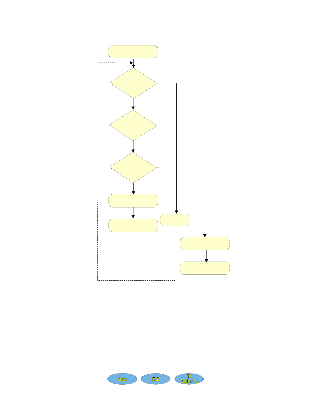
Repair Flow
The following is the repair flow for Level 3 service. See Figure 5-1.
• Inspection is performed to identify mechanical faults on the phone. Check for mechanical dam-
ages and dust in the display.
• Go/No Go Test is used to measure radio parameters according to GSM specifications.
• On-the-Air Call is made to a stationary telephone to check acoustic functionality.
• On-the-Air Call/HF is made to a stationary telephone using a handsfree kit to check system con-
nector functionality if there is suspicion that HF doesn’t work.
• Warranty Seal is to be placed over the left torx screw at the bottom.
• Repair is carried out of components stated in the Repair Actions. After repair the phone is tested
from inspection again.
5-3
Page 4
Service of the Telephone LZB 119 2508 R1A
Repair
To higher level
From Customer
Inspection
OK
Go/No Go
Test
OK
On-The-Air Call
OK
Warranty Seal
To Customer
Fail
Fail
Fail
Fail
OK
5-4
Warranty Seal
of service
Figure 5-1. Repair Flow
Page 5
LZB 115 2508 R1A Service of the Telephone
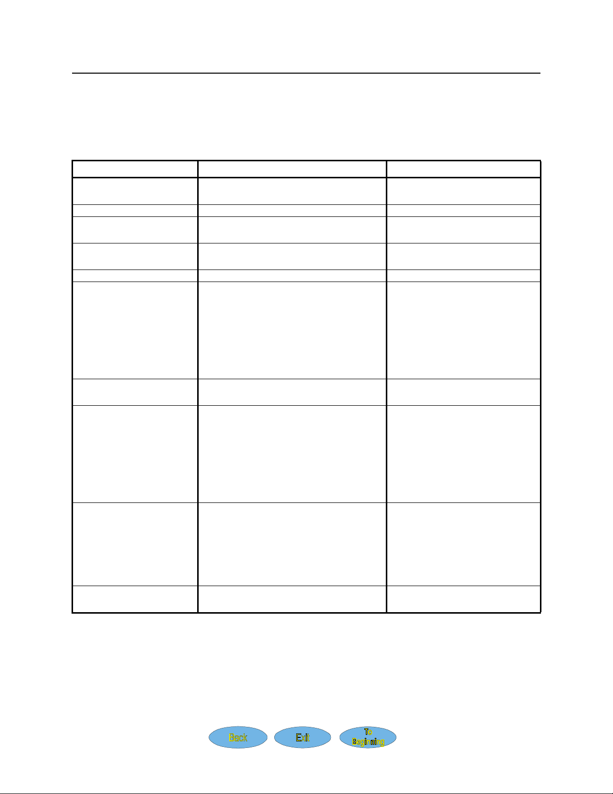
Common Telephone Failures
Refer to Table 5-1 for a list of common failures of the CA638 and CF688 Mobile Phones, the probable
cause of the failure, and the component to be changed.
Table 5-1. Common Failures
Failure Probable Cause
Phone not getting signal Damaged antenna
Damaged antenna connector
Top Indicator not lit LEDs
Volume keys Bad/Broken or badly positioned dome
foil
Keypad keys not func-
tioning
Display segments missing Display is broken Exchange the display assembly
Phone won’t turn on Bad system connector contacts
Bad keypad Exchange the keypad
Broken system connector
Keypad key “ON” may be damaged
Change antenna
Change antenna connector
Change LEDs
Exchange the dome foil
Exchange the volume keys
Check and clean all contacts at
system connector and contact
pads on the PCB
Exchange connector
Check and, if necessary,
exchange the keypad
Action
Phone doesn’t power up
when flip opened
No audio Sound channel at flip may be clogged*
Battery not charging Battery or system connector may be
Peripherals not
functioning
* For CF688 only.
All other measurements are not possible to repair at Level 3. Send the phone to a higher level of service.
Active flip* may be broken Exchange the flip *
Clean or exchange flip *
Contacts at system connector may be
broken
Microphone broken
Earphone broken
damaged
System connector may be damaged
Check and exchange system
connector
Exchange microphone
Exchange earphone
Check and Exchange battery
Check and clean all contacts at
system connector and contact
pads on PCB
Check and exchange system
connector
Check and exchange system
connector
5-5
Page 6

Service of the Telephone LZB 119 2508 R1A
Exchangeable Parts
The following are the exchangeable parts for the CA638 and CF688 Mobile Phones. See Figure 5-2 and
Figure 5-3.
NOTE
Use both figures as references when reading the following list.
1. Frame
2. Antenna
3. Antenna Connector
4. Buzzer
5. Front cover
6. Display assembly(includes LCD, light guide, and LCD connector)
7. Keypad
8. System connector
9. Warranty seal
10. SIM cover
11. SIM reader
12. Microphone
13. Microphone gasket
14. Flip Door *
15. Hinge *
16. Side Volume keys *
See Figure 5-9, Figure 5-17 and Figure 5-18 for the following replaceable components:
• Dome foil (For side keys)
• Light emitting diodes (LCD)
• Light emitting diodes (Keypad)
• Capacitor (Clock backup)
• Loudspeaker connector
* Note: Only on CF688.
Please contact your Regional Service Manager for the latest spare parts list with part numbers and pricing.
NOTE
The spare parts lists distributed by the Regional Service Managers are more detailed
than the information in this manual. Please reference the item name and the phone
model when requesting spare parts information.
5-6
Page 7

LZB 115 2508 R1A Service of the Telephone
Figure 5-2. CA638 Exchangeable Parts
5-7
Page 8

Service of the Telephone LZB 119 2508 R1A
5-8
Figure 5-3. CF688 Exchangeable Parts
Page 9

LZB 115 2508 R1A Service of the Telephone
Disassembly
CAUTION
The telephone should only be opened in a dust-free area where ESD protection is
available and used (anti-static mats, wrist straps, etc.). Refer to Chapter 1.
CAUTION
Touching the internal components of the phone with bare hands will deposit skin
oils on the components and disrupt functionality. Always wear latex gloves when
repairing the phone.
NOTE
Only specific levels of Service Centers are authorized to disassemble the telephone
(please contact your Regional Service Manager). Failure to comply with this will
void the warranty of the telephone.
See Figure 5-2 and Figure 5-3 as needed throughout this section. Perform the following procedure to disassemble the phone:
1. Remove the battery. See Figure 5-4.
Figure 5-4. Battery Removal
2. Remove the antenna by pulling it away from the phone and place the phone with the frame turned
upwards.
3. Remove the four screws from the frame.
4. Separate the front cover from the frame and PCB.
5. Unscrew the two PCB screws along with the top screw and remove them.
6. Separate the PCB from the frame by lifting it upwards.
5-9
Page 10

Service of the Telephone LZB 119 2508 R1A
7. Place the PCB on an ESD-protected surface.
8. Use a tweezer to remove the plastic display assembly cover from the front cover. See Figure 5-14.
9. Place the display assembly with the display turned upwards on the ESD-protected surface.
10. Place a protection tape over the display.
NOTE
Do not touch the display with your hands.
11. Remove the keypad from the front cover by lifting it upwards. See Figure 5-12.
5-10
Page 11

LZB 115 2508 R1A Service of the Telephone
Reassembly
See Figure 5-2 and Figure 5-3 as needed throughout this section. Perform the following procedure to reassemble the phone:
1. Place the keypad in the front cover.
2. Place the display on the display gasket with the gray side up, the black pad toward the top of the
phone. See Figure 5-5.
NOTE
The display should be aligned with the bottom edge against the keypad to allow
room to align the plastic keypad cover.
Figure 5-5. Display Alignment
3. Align the plastic keypad cover to the mounting pin in the front cover assembly. See Figure 5-5.
4. Gently press down on the plastic keypad assembly until it clicks onto the mounting pin.
5. Use the small flat-head screwdriver to align the display against the plastic elbow on the keypad
cover. See Figure 5-5.
6. Clean the back cover and the PCB with compressed air.
7. Replace the microphone elastomer with a new one.
8. Remove the protection tape from the display.
NOTE
Do not touch the display with your hands. Wear latex gloves.
9. Clean the front cover and the display assembly with compressed air.
10. Clean the frame and the PCB with compressed air.
11. Place the PCB in the frame.
12. Place the two PCB screws along with the top screw in the holes and use the screwdriver to tighten
the screws.
13. Place the frame on the front cover.
5-11
Page 12

Service of the Telephone LZB 119 2508 R1A
14. Replace the four screws in the frame.
15. Hold the telephone in your hand with the antenna connector upwards.
16. Push the antenna into the hole until a click is heard. If the antenna is not correctly fitted into the
back cover, press the antenna downwards and twist until it is properly pushed down into the connector.
17. Insert the battery pack into the telephone and push until a click is heard. See Figure 5-6.
Figure 5-6. Battery Connection
5-12
Page 13

LZB 115 2508 R1A Service of the Telephone
Replacement of Mechanical Parts
CAUTION
The telephone should only be opened in a dust-free area where ESD protection is
available and used (anti-static mats, wrist straps, etc.). Refer to Chapter 1.
CAUTION
Touching the internal components of the phone with bare hands will deposit skin
oils on the components and disrupt functionality. Always wear latex gloves when
repairing the phone.
NOTE
Only specific levels of Service Centers are authorized to disassemble the telephone
(please contact your Regional Service Manager). Failure to comply with this will
void the warranty of the telephone.
See Figure 5-2 and Figure 5-3 as needed throughout this section.
Antenna
Perform the following procedure to replace the antenna:
1. Hold the telephone in your hand with the antenna pointing upwards.
2. Remove the antenna by pulling it out from the telephone.
3. Take a new antenna.
4. Hold the telephone in your hand with the antenna connector upwards.
5. Press the antenna into the antenna connector until a click is heard.
6. In case the antenna is not correctly fitted into the back cover; press the antenna downwards and
twist until it is properly pushed down into the connector.
Front Cover
See Figure 5-7. Perform the following procedure to replace the front cover:
1. Disassemble the telephone as described in Disassembly, steps 1 to 7.
2. Remove the LCD assembly using tweezers.
3. Remove the keypad from the front cover by lifting it upwards.
4. Take a new front cover.
5. Remove the dome foil from the old front cover and place it in the new one. See Figure 5-9.
CAUTION
Do not touch the dome foil with your hands. Use a tweezer.
5-13
Page 14

Service of the Telephone LZB 119 2508 R1A
6. Remove the protection tape from the display.
7. Reassemble the telephone as described in Reassembly, steps 1 to 17.
Figure 5-7. Front Covers
Frame
See Figure 5-8. Perform the following procedure to replace the frame:
1. Disassemble the telephone as described in Disassembly, steps 1 to 3.
2. Remove the frame.
3. Take a new frame.
4. Reassemble the telephone as described in Reassembly, steps 13 to 17.
5-14
Figure 5-8. Frame
Page 15

LZB 115 2508 R1A Service of the Telephone
Dome Foil for Side Volume Keys
See Figure 5-9. Perform the following procedure to replace the dome foil for the side volume keys:
1. Disassemble the telephone as described in Disassembly, steps 2 to 10.
2. Place a protection tape over the display.
3. Use a tweezer to remove the dome foil from the front cover.
4. Use the tweezer to place a new dome foil in the front cover.
NOTE
Do not touch the done foil with your hands. Use the tweezer.
5. Reassemble the telephone as described in Reassembly, steps 1 to 17.
Figure 5-9. Removing the Dome Foil
Side Volume Keys
See Figure 5-10. Perform the following procedure to replace the side volume keys:
1. Disassemble the telephone as described in Disassembly, steps 1 to 10.
2. Remove the dome foil. Refer to Dome Foil for Side Volume Keys.
3. Hold the telephone in your hand with the side volume keys towards you.
4. Use a tweezer to remove the side volume keys. See Figure 5-10.
CAUTION
Use care to avoid damages to the front cover.
5. Take a new package of side volume keys.
5-15
Page 16

Service of the Telephone LZB 119 2508 R1A
6. Place the new side volume keys in the front cover.
NOTE
The side volume keys can be mounted in one way only as guided by the key con-
tour. If they don´t fit, turn them 180º.
7. Push the two side buttons separately until you hear a click.
8. Replace the dome foil. Refer to Dome Foil for Side Volume Keys.
9. Reassemble the telephone as described in Reassembly, steps 2 to 17.
Figure 5-10. Side Volume Keys
SIM Cover/Card Holder
See Figure 5-11. Perform the following procedure to replace the SIM cover:
1. Remove the battery. See Figure 5-4.
2. Remove the SIM cover by pulling it upwards from the phone.
3. Take a new SIM cover and replace it.
4. Replace the battery. See Figure 5-6.
5-16
Figure 5-11. Removing the SIM Cover
Page 17

LZB 115 2508 R1A Service of the Telephone
Keypad
See Figure 5-12. Perform the following procedure to replace the keypad:
1. Disassemble the telephone as described in Disassembly, steps 1 to 11.
2. Remove the old keypad.
3. Take a new keypad and place it in the front cover.
4. Reassemble the telephone as described in Reassembly, steps 1 to 17.
Figure 5-12. Removing the Keypad
Loudspeaker
See Figure 5-13. Perform the following procedure to replace the loudspeaker and holder:
1. Disassemble the telephone as described in Disassembly, steps 1 to 10.
2. Place the display assembly with the display turned upwards on the ESD-protected surface.
3. Remove the loudspeaker with a screwdriver.
4. Remove the old loudspeaker tape.
5. Place new loudspeaker tape in the front cover.
6. Fit the speaker onto the tape.
NOTE
Take note of the position of the gold contacts. Reference the outline on the inside of
the front panel.
7. Press on the loudspeaker for a few seconds until it sticks on the front.
CAUTION
Do not touch the gold-plated connector with your hands. Wear latex gloves.
8. Reassemble the telephone as described in Reassembly, steps 2 to 17.
5-17
Page 18

Service of the Telephone LZB 119 2508 R1A
Figure 5-13. Removing the Loudspeaker
Display Assembly
See Figure 5-14. Perform the following procedure to replace the display assembly:
1. Disassemble the telephone as described in Disassembly, steps 1 to 8.
2. Place the PCB on an ESD-protected surface.
3. Take a new display assembly and remove the protection film from the display.
4. Place the display assembly in the front with the LCD towards the window.
5. Use the two plastic spines to align the display assembly. See Figure 5-5 and Figure 5-14.
NOTE
Do not touch the display with your hands. Wear latex gloves.
6. Reassemble the telephone as described in Reassembly, steps 9 to 17.
Figure 5-14. Display Assembly
5-18
Page 19

LZB 115 2508 R1A Service of the Telephone
Plastic Connector (LCD)
Perform the following procedure to replace the plastic connector:
1. Disassemble the telephone as described in Disassembly, steps 1 to 10.
2. Grasp the old plastic connector with a tweezer and remove it.
NOTE
Take note of the position of the connector before removing it.
3. Take a new plastic connector with the tweezer and place it in the display assembly.
CAUTION
Do not touch the connector or the display with your hands. Wear latex gloves.
4. Reassemble the telephone as described in Reassembly, steps 9 to 17.
Microphone with Holder
See Figure 5-15. Perform the following procedure to replace the microphone and holder:
1. Disassemble the telephone as described in Disassembly, steps 1 to 10.
2. Use a tweezer to remove the elastomer from the microphone.
3. Use a tweezer to remove the old microphone and gasket from the front cover.
NOTE
Take note of the alignment of the old elastomer and microphone in the gasket, and
align the new components the same way.
4. Take a new microphone and place it into the bottom of a new microphone holder.
CAUTION
Do not touch the contact surface of the microphone or elastomer contacts. Wear
latex gloves.
5. Place the microphone and holder in the front cover.
6. Place a new elastomer on the microphone.
7. Reassemble the telephone as described in Reassembly, steps 2 to 17.
Figure 5-15. Removing the Microphone
5-19
Page 20

Service of the Telephone LZB 119 2508 R1A
Replacement of PCB Components
CAUTION
The telephone should only be opened in a dust-free area where ESD protection is
available and used (anti-static mats, wrist straps, etc.). Refer to Chapter 1.
CAUTION
Touching the internal components of the phone with bare hands will deposit skin
oils on the components and disrupt functionality. Always wear latex gloves when
repairing the phone.
NOTE
Only specific levels of Service Centers are authorized to disassemble the telephone
(please contact your Regional Service Manager). Failure to comply with this will
void the warranty of the telephone.
System Connector
See Figure 5-16. Perform the following procedure to replace the system connector:
1. Disassemble the telephone as described in Disassembly, steps 1 to 7.
2. Place the PCB on an ESD-protected surface.
3. Remove the system connector from the PCB by pulling it away from the gold-plated PCB contact
pad.
4. Take a new system connector.
5. Push the system connector onto the PCB´s gold-plated contact pad.
CAUTION
Use care not to damage the components or the gaskets on the phone.
NOTE
The system connector can only be mounted in one way.
6. Clean the frame and the PCB with compressed air.
7. Reassemble the telephone as described in Reassembly, steps 10 to 17.
5-20
Page 21

LZB 115 2508 R1A Service of the Telephone
Figure 5-16. Mounting the System Connector
Speaker Connector Replacement
See Figure 5-17. Perform the following procedure to replace the speaker connector:
1. Disassemble the telephone as described in Disassembly, steps 1 to 7.
2. Place the PCB on an ESD-protected surface with the speaker connector facing upwards.
3. Take note of how the speaker connector is positioned.
CAUTION
Solder carefully. Solder pads can easily come loose from the PCB.
4. Desolder the speaker connector from the PCB.
5. Clean the solder areas with air suction or a solder braid.
6. Place the new speaker connector on the PCB in the same position as the old speaker connector.
7. Solder the speaker connector.
8. Clean all contacts with an approved PCB cleaning solution.
9. Clean the PCB with compressed air.
10. Reassemble the telephone as described in Reassembly, steps 10 to 17.
Figure 5-17. Buzzer, Speaker Connector, and Backup Capacitor
5-21
Page 22

Service of the Telephone LZB 119 2508 R1A
Buzzer Replacement
See Figure 5-2. Perform the following procedure to replace the buzzer:
1. Disassemble the telephone as described in Disassembly, steps 1 to 7.
2. Place the PCB on an ESD-protected surface with the buzzer facing upwards.
CAUTION
Solder carefully. Solder pads can easily come loose from the PCB.
3. Remove the speaker connector. Refer to Speaker Connector Replacement.
4. Desolder the buzzer from the PCB.
5. Clean the solder areas with air suction or a solder braid.
6. Place the new buzzer on the PCB with the hole in the plastic cover facing the short end of the PCB.
7. Solder the buzzer.
8. Replace speaker connector. Refer to Speaker Connector Replacement.
9. Clean all contacts with an approved PCB cleaning solution.
10. Clean the PCB with compressed air.
11. Reassemble the telephone as described in Reassembly, steps 10 to 17.
NOTE
The backup capacitor is not attached to the buzzer. See Figure 5-17.
5-22
Page 23

LZB 115 2508 R1A Service of the Telephone
LED Replacement
See Figure 5-18. Perform the following procedure to replace the LEDs:
1. Disassemble the telephone as described in Disassembly, steps 1 to 7.
2. Place the PCB on an ESD-protected surface with the LEDs facing upwards.
CAUTION
Solder carefully. Solder pads can easily come loose from the PCB.
3. Take note of how the LEDs are positioned on the PCB.
4. Desolder the LEDs from the PCB.
5. Clean the solder areas with air suction or a solder braid.
6. Place the new LEDs on the PCB in the same positions as the old ones.
7. Solder the LEDs.
8. Clean all contacts with an approved PCB cleaning solution.
9. Clean the PCB with compressed air.
10. Reassemble the telephone as described in Reassembly, steps 10 to 17.
Figure 5-18. LED Placement
Return to Service Checkout
Perform an Inspection and an On-the-Air Call before returning the phone to service.
5-23
 Loading...