

Page 1

OM Instructions
Contents
1 Design, Function and Operation..................................................................3
1.1 General.............................................................................................3
1.2 Mechanical Parts..............................................................................4
1.3 Start-Up and Shutdown Procedures.................................................8
1.3.1 Start-Up Procedure ...............................................................8
1.3.2 Shutdown Procedure......................................... ...... ..... .........8
1.3.3 Restarting the BRU3 (Warm Start).......................................9
1.3.4 Manual Restart of the BRU3 ................................................9
1.3.5 Manual Restart of a BRU3 in Stand Alone Mode ..............10
1.4 Network Connections.....................................................................12
1.4.1 General................................................................................12
1.4.2 Telephone Modem Boards..................................................13
1.5 Logic Units.....................................................................................17
1.5.1 General................................................................................17
1.5.2 Connections ........................................................................ 17
1.5.3 LEDs...................................................................................18
1.5.4 Reset Button........................................................................18
1.6 Radio Units.....................................................................................19
1.6.1 General................................................................................19
1.6.2 Radio Operation..................................................................21
1.6.3 Reset.................................................................................... 21
1.6.4 Connectors..........................................................................21
1.7 Power Supply................................................................................. 22
1.7.1 General................................................................................22
1.7.2 FE Power Supply Unit (FPU).............................................23
1.7.3 FE Battery Unit (FBU) .......................................................26
1.7.4 FE Heating Unit (FHU) ......................................................27
1.8 Alarms............................................................................................28
2 Maintenance ..............................................................................................29
2.1 General...........................................................................................29
2.2 Equipment Required....................................................................... 30
BRU3 MANUAL, Doc.no: 1543-ANNA 805 08 Uen Rev H, 2003-06-10
Page 2

BRU3 MANUAL
2.3 Documentation Required................................................................30
2.4 Maintenance to be Performed.........................................................31
2.4.1 Visual and Preventive Maintenance....................................31
2.4.2 Battery Test ............................ ..... ...... ..................................33
2.5 Function Check...............................................................................34
2.5.1 General ................................................................................34
2.5.2 Equipment Required............................................................34
2.5.3 Check of Internal Power Supply (Mains and Battery) ........35
2.5.4 FBTEST Board Test............................................................37
2.5.5 Channel Unit Output Power ................................................38
2.5.6 Transmitter Deviation..........................................................41
2.5.7 Bit Errors at high Signal Levels ..........................................42
2.5.8 Receiver Sensitivity.............................................................44
2.5.9 Receiver Sensitivity at Frequency Deviation ......................46
2.5.10 Antenna input Signal................... ...... ...... ............................48
2.5.11 Transmitter Antenna VSWR ...............................................49
2.5.12 Hardware Alarm Status .......................................................52
3 Troubleshooting .........................................................................................54
3.1 General............................................................................................54
3.2 Power Supply Units........................................................................55
3.2.1 FE Power Supply Unit (FPU)..............................................55
3.2.2 FE Battery Unit (FBU)............................ ..... ...... .................56
3.3 Logic and modem units...................................................................57
3.3.1 FE Computer Board (FCB) ..................... ............................57
3.3.2 FE Modem Board (FMB) & FE Adaptation Board (FAB) .58
3.3.3 FE Connection Board (FNB)...............................................58
3.4 Radio units......................................................................................59
3.4.1 FE Radio Board (FRB) ........................................................59
3.5 FE Heating Unit (FHU) ..................................................................59
3.5.1 FE Heating Board (FHB).....................................................59
The contents of this document are subject to revision without notice due to continued progress in methodology,
design and manufacturing.
Ericsson shall have no liability for any errors or damages of any kind resulting from the use of this document.
BRU3 MANUAL, Doc.no: 1543-ANNA 805 08 Uen Rev H, 2003-06-10
Page 3
OPERATION AND MAINTENANCE, MODULE B1 3 (60)
1 Design, Function and Operation
1.1 General
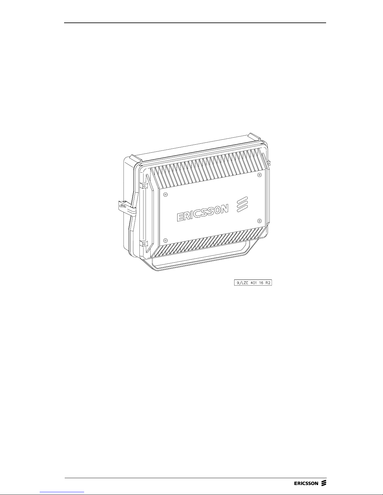
Figure 1 BRU3 (exterior).
This section describes the design, function and operation of the Mobitex Base
Radio Unit 3 (BRU3).
During normal operation, all actions neces s ary for the operation and check of
the BRU3 are carried out at the Network Control Centre (NCC). When
operating the BRU3 on site, the following equipment is required:
• Portable PC including VT-100 emulation software.
• FE Console Cable TSRA 902 0190 for connection of the terminal to the
BRU3 connector "P1-CONSOLE".
•FBTEST
BRU3 MANUAL, Doc.no: 1543-ANNA 805 08 Uen Rev H, 2003-06-10
Page 4

4 (60) BRU3 MANUAL
For a description on how to connect the por tabl e PC to the BRU3, please refe r
to Shutdown Procedure in the Start-Up and Shutdown Procedures section
below.
BRU3 is a complete one-chann el compact radio base station which uses 8 kb ps
data signalling and is designed for the 400, 800 or 900 MHz band. The BRU3,
which may be installed both outdoors and indoors, is a link between the mobile
terminals (MOB) and the area exchanges (MOX) in the MOBITEX Network.
1.2 Mec hanical Parts
The BRU3 consists of two main mechanical parts, the FE Case Bottom Frame
(FBF) and FE Case Top Frame (FTF).
The FBF is fixed on site. This part has weather-protected throughputs for the
cabling, the FE Connection Board (FNB), the FE Power Supply Unit (FPU) and
the FE Battery Unit (FBU) for power supply backup.
The other part, the FTF, is hinged to the bottom part and works as a cover and
cooling flange, offering good thermal management for the BRU3. The FTF
includes the FE Computer Board (FCB), the FE Modem Board (FMB), the FE
Radio Board (FRB), the FE Filter Module (FFM) and the FE Heating Unit
(FHU).
The BRU3 is lockable to prevent unauthorized access to the unit. To avoid
corrosion, the painted white mechanical parts are made of corrosion-resistant
material.
BRU3 MANUAL, Doc.no: 1543-ANNA 805 08 Uen Rev H, 2003-06-10
Page 5
OPERATION AND MAINTENANCE, MODULE B1 5 (60)
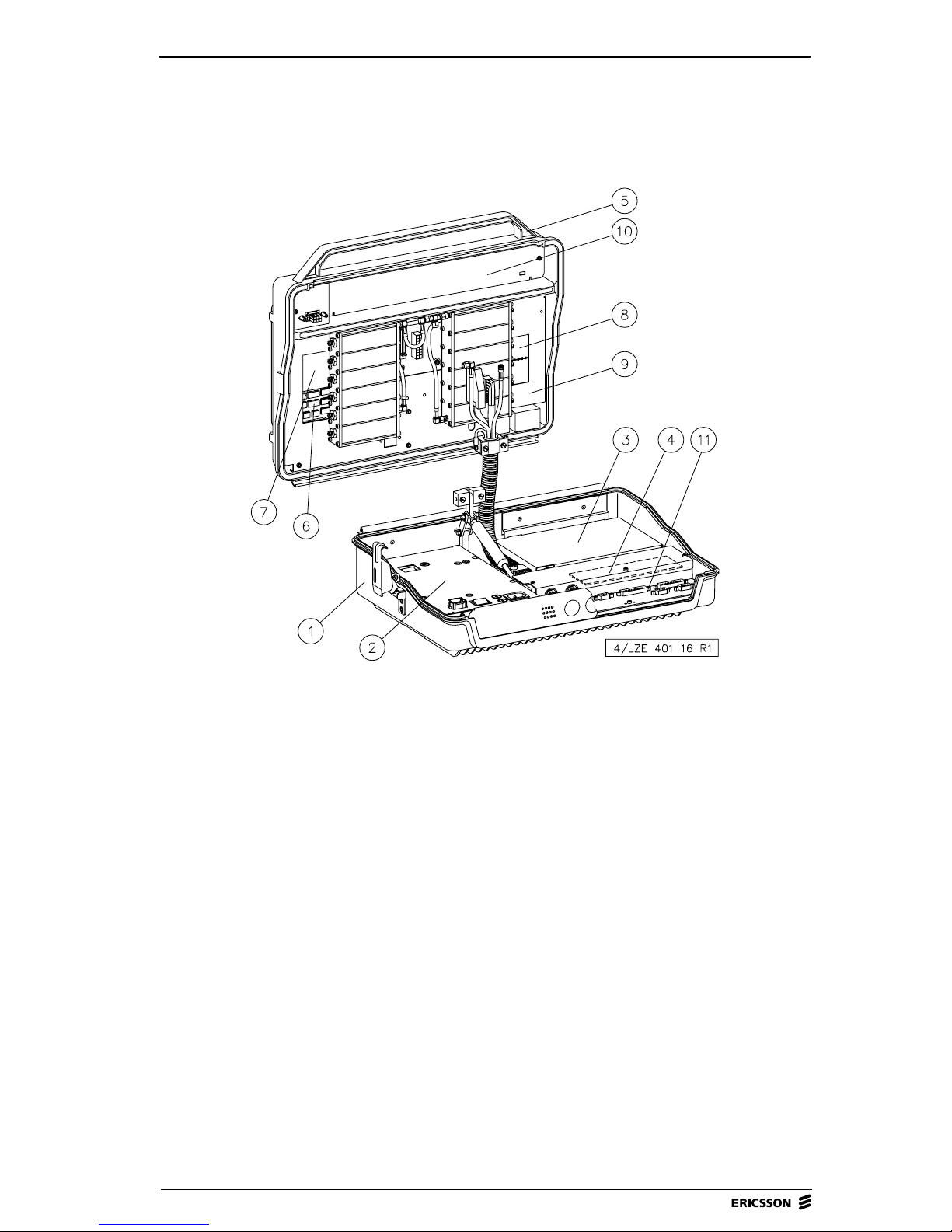
Figure 2 BRU3 (interior).
1 FE Case Bottom Frame (FBF)
2. FE Power Supply Unit (FPU)
3. FE Battery Unit (FBU)
4. FE Adaptation Board (FAB)
5. FE Case Top Frame (FTF)
6. FE Computer Board (FCB)
7. FE Modem Board (FMB)
8. FE Radio Board (FRB)
9. FE Filter Module (FFM)
10. FE Heating Unit (FHU)
11. FE Connection Board (FNB)
BRU3 MANUAL, Doc.no: 1543-ANNA 805 08 Uen Rev H, 2003-06-10
Page 6
6 (60) BRU3 MANUAL
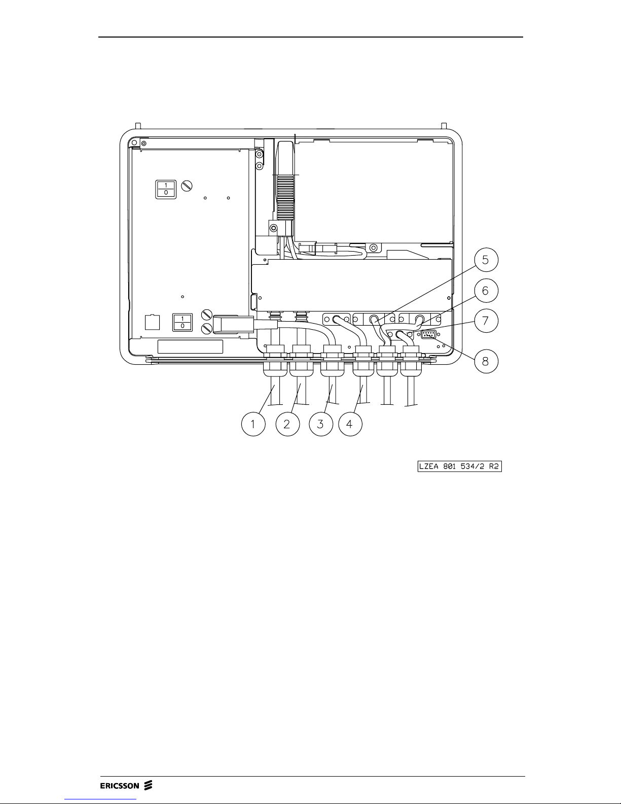
Figure 3 BRU3 ext ernal co nnections.
1. RX Antenna
2. TX Antenna
3. Power Connection
4. Telephone Line Connection
5. Modem Connection RS422C
6. Modem Connection RS232C
7. Alarm Connection
8. Console Connection
BRU3 MANUAL, Doc.no: 1543-ANNA 805 08 Uen Rev H, 2003-06-10
Page 7

OPERATION AND MAINTENANCE, MODULE B1 7 (60)
Pos 2 is used as the antenna connection when a combined RX/TX antenna is
used.
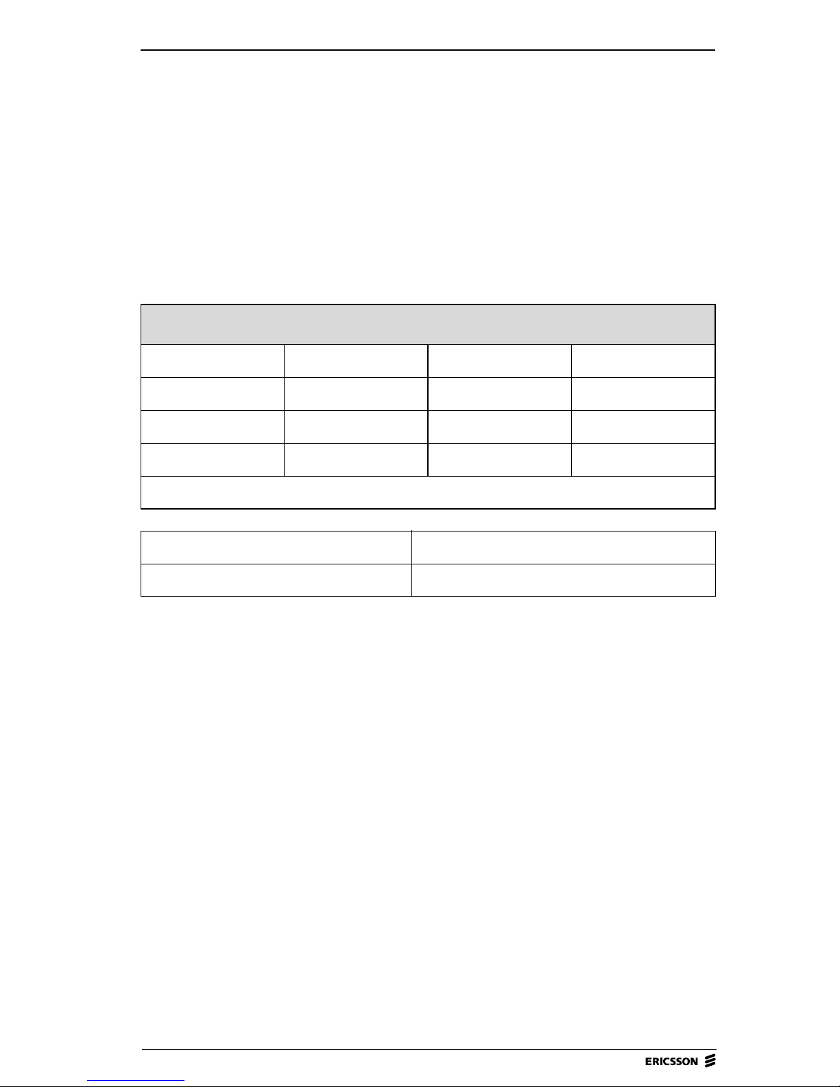
The table below gives a brief description of the BRU3 connections used. The
position numbers found in the “Position” column refer to the corresponding
position numbers in Figure 3.
Pos. Connector
3 MAINS INLET IEC 120/230V AC inpu t fro m t he BRU 3 site
1 RX ANT. TNC Signals f r om the rece iving ante n na (RX).
2 TX ANT.
ALT.
RX/TX ANT.
4 P3-TELEPHONE 9p d-sub Telephone line connection.
5 P5-RS422B 25p d-sub Connection to MOX via balanced serial
Type of
Connector
power supply.
TNC Signals to the tr ansmitti ng antenna T X.
Signals to/from th e co mb in ed RX/TX
antenna.
interface RS422B.
Connection To/From
6 P4-RS232C 25p d-sub Connection to MOX via un-balanced
7 P2-ALARM 9p d-sub Connection used for external alarm.
8 P1-CONSOLE 9p d-sub Connection used for Console/ NODOP
BRU3 MANUAL, Doc.no: 1543-ANNA 805 08 Uen Rev H, 2003-06-10
serial interface RS23 2 C
Defined by the operat or.
terminal.
Page 8

8 (60) BRU3 MANUAL
1.3 Start-Up and Shutdown Procedures
Note! When startin g u p the BRU3 after installation, follow the
instructions under Hardware Commissioning Procedure and
Software Commissioning Procedure in the Commissioning
Procedure section of the BRU3 - General module.
1.3.1 Start-Up Procedur e
When starting up the BRU3, do as follows:
1. Set the "MAINS SWITCH" located on the FE Po wer Supply Unit (FPU)
to positi on "1".
2. Set the "BATTERY SWITCH" located on the FPU to position "1".
3. Check that the yellow status LEDs are lit on the FE Co mputer Board
(FCB) and the FPU.
4. Check, after a few seconds, that no red alarm LEDs are lit on the FCB or
FPU.
Note! The warm-up time for the BRU3 is required to be at least 30
minutes, before the transmitter is activated. Specifications for the
BRU3 are valid after this period.
1.3.2 Shutdown Procedure
To ensure minimal traffic and data loss when the power to the node has to be
shut down, always perform the following shutdown procedure:
1. Connect the portable PC via the FE Console Cable TSRA 902 0190 to the
port "P1-CONSOLE" on the FE Connection Board (FNB).
2. Press return to get the NODOP prompt NODOP>
Note! If the node has just s tar ted, it will take a little while before
NODOP is functioning.
3. Give the command HALT 120 on the NODOP terminal.
BRU3 MANUAL, Doc.no: 1543-ANNA 805 08 Uen Rev H, 2003-06-10
Page 9

OPERATION AND MAINTENANCE, MODULE B1 9 (60)
4. When you are asked to verify the command, enter Y.
5. The shutdown procedure will stop all incoming traffic and close all open
files. A message will be displayed on the console terminal when the node
may be switched off.
1.3.3 Res tarting the BRU3 (Warm Start)
Restart (RESET) can be performed either of the entire node or of certain units.
• By command from an NCC operator.
• By the NODOP command BOOT using a terminal.
• Manually for different units.
• Automatically, by the software for the different units.
1.3.4 Manual Restart of the BRU3
The manual restart procedure below should be used only if NODOP does not
respond to any command. Otherwise, use the NODOP BOOT command.
Pressing the reset button will cause an immediate restart of the BRU3, without
ensuring a proper node shutdown. The restart may result in loss of user traffic
and data.
The reset button (SW1) is located on the FE Computer Board (FCB).
After the restart, the BRU3 will be reinitiated, implying logical connection of
all serial communication.
BRU3 MANUAL, Doc.no: 1543-ANNA 805 08 Uen Rev H, 2003-06-10
Page 10

10 (60) BRU3 MANUAL
1.3.5 Manual Restart of a BRU3 in Stand Alone Mode
This is short description on how to boot the BRU3 using a PC and a terminal
program. When the connection is up and running (use 19200 bps 8N1), cold
start the BRU3 by switch ing the power on and off. Afte r a short while, some text
will be displayed on the terminal.
Steps 1-7 below d escrib e ho w to do wnload so ftw are from t he PC to th e BRU3.
These steps are required only if no main software is present on the BRU3 disks.
To check if the main software is present on the disks, use the command “DI”.
Check if there is a “.mfe” (like the one stated in step 6) file on either of the disks
wp1:, wp2:, wp3:, etc. The name for the di sks (wp1, etc.) that are present can be
seen at the start-up.
Note! Do not forget the colon “:” after the disk name.
File names stated in the instruction are only examples of file na mes and sho uld
be replaced by correct names.
1. On request, enter !!! and set the thumb wheel in position 7 for the
command prompt (CMD>).
2. Type ASY at the CMD> prompt.
3. Send the config (config.bin) with the terminal program using zmodem.
4. When the download is finished, the BRU3 will reboot.
5. Get the BRU3 into software transfer mode again by following steps 1 and
2 (if you do not already have a CMD> prompt).
6. Send the main software (main_sw.mfe) with the terminal program using
zmodem.
7. When the download is finished, the BRU3 will reboot.
8. Get the BRU3 into software transfer mode again by following steps 1 and
2 (if you do not already have a CMD> prompt).
9. Type “B WP2: MAIN_SW.MFE” at the prompt.
BRU3 MANUAL, Doc.no: 1543-ANNA 805 08 Uen Rev H, 2003-06-10
Page 11

OPERATION AND MAINTENANCE, MODULE B1 11 (60)
10. The BRU3 should reboot and you will receive the CMD> prompt.
Type “B WP2: MAIN_SW.MFE” again and the BRU3 will reboot once
more.
11. When the second reboot is finished, the BRU3 will display
“USERNAME:”.
(It may take a while for the BRU3 to warm up)
12. Pr ess ente r twice t o get pas t the USE RNAM E and PASSWORD prompts .
13. Issue the command “SET BOOT MASTER WP2: MAIN_SW.MFE Y” at
the NODOP prompt.
14. Check that the software is installed permanently by issuing the NODOP
command “SHOW BOOT”.
The following step can now be performed, but in your case it should not be
necessary:
Enter !!! and set the thumb wheel in position 0 for normal mode.
Note! If the main software is still p r esent on the WP2: disk, steps 3-8
may be omitted. You can check if the software is present by
issuing the command DI at the command prompt (that is, right
before step 2).
BRU3 MANUAL, Doc.no: 1543-ANNA 805 08 Uen Rev H, 2003-06-10
Page 12

12 (60) BRU3 MANUAL
1.4 Network Connections
Figure 4 Line interface block diagram.
1.4.1 General
There are three alternative line interfaces for connection to MOX:
• telephone modem V.32
• balanced serial interface V.11 (RS422B)
• unbalanced serial interface V.28 (RS232C).
BRU3 MANUAL, Doc.no: 1543-ANNA 805 08 Uen Rev H, 2003-06-10
Page 13
OPERATION AND MAINTENANCE, MODULE B1 13 (60)
The choice between telephone modem, balanced serial interface and
unbalanced serial interface, is made via hardware strapping, i.e., only one line
interface alternative is available at a time. In some BRU3 variants the telephone
modem is not applicable which means th at only a balanced serial interface and
an unbalanced serial interface are available.
The hardware strapping is made by setting switch 2 (SW2) on the FE Computer
Board as follows:
Switch 2
SW2:1 SW2:2 SW2:3 Comments
Open or Closed Open Open V.32bis
Open Open Closed V.28 (RS232)
Closed Open Closed V.11 (RS422)
Other altern atives not allowed.
SW2:4 Comments
Open OEM-Strap
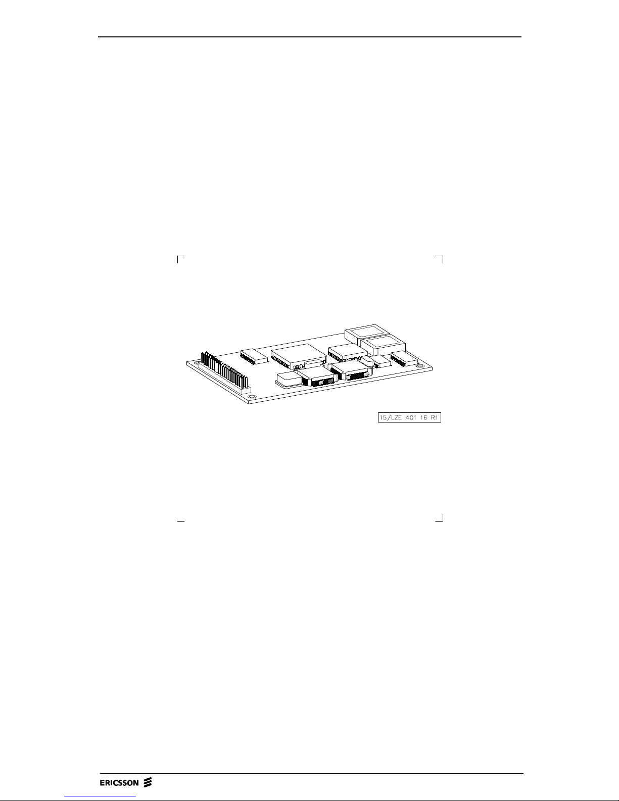
1.4.2 Telephone Modem Boards
The telephone modem, whi ch supp orts th e CCITT V. 32 and V.3 2bis standa rds,
consists of two separate boar ds , the FE Modem Board V.32 (FMB) and the FE
Adaptation Board (FAB). Depending on national requirements issued by the
telecommunications administration in each country, different versions of the
FAB may be used. Also, the information regarding telephone modem in this
manual may not be applicable to all BRU3 variants.
Two-wire leased, four-wire leased or switched lines are used for data
transmission. The maximum transmission rate is 14 400 bits/sec. The modem is
connected to the computer part via a synchronous serial circuit.
Asynchronously transferred AT/Hayes commands are used for modem
configuration and check.
BRU3 MANUAL, Doc.no: 1543-ANNA 805 08 Uen Rev H, 2003-06-10
Page 14
14 (60) BRU3 MANUAL
The software used by the mode m is installed from the main processor and sto red
in a memory.
The FMB does not include a reset button. The FMB and F AB are reset when the
main processor is reset.
Connectors
FE Modem Board (FMB)
Figure 5 FE Modem Board (FMB).
P1 2x20 pin header with 0.1" module: For connecting the V.24 interface
and power from the main board of the BRU3, and also, conn ection of
the analog/digital signals between the FMB and FAB.
BRU3 MANUAL, Doc.no: 1543-ANNA 805 08 Uen Rev H, 2003-06-10
Page 15
OPERATION AND MAINTENANCE, MODULE B1 15 (60)
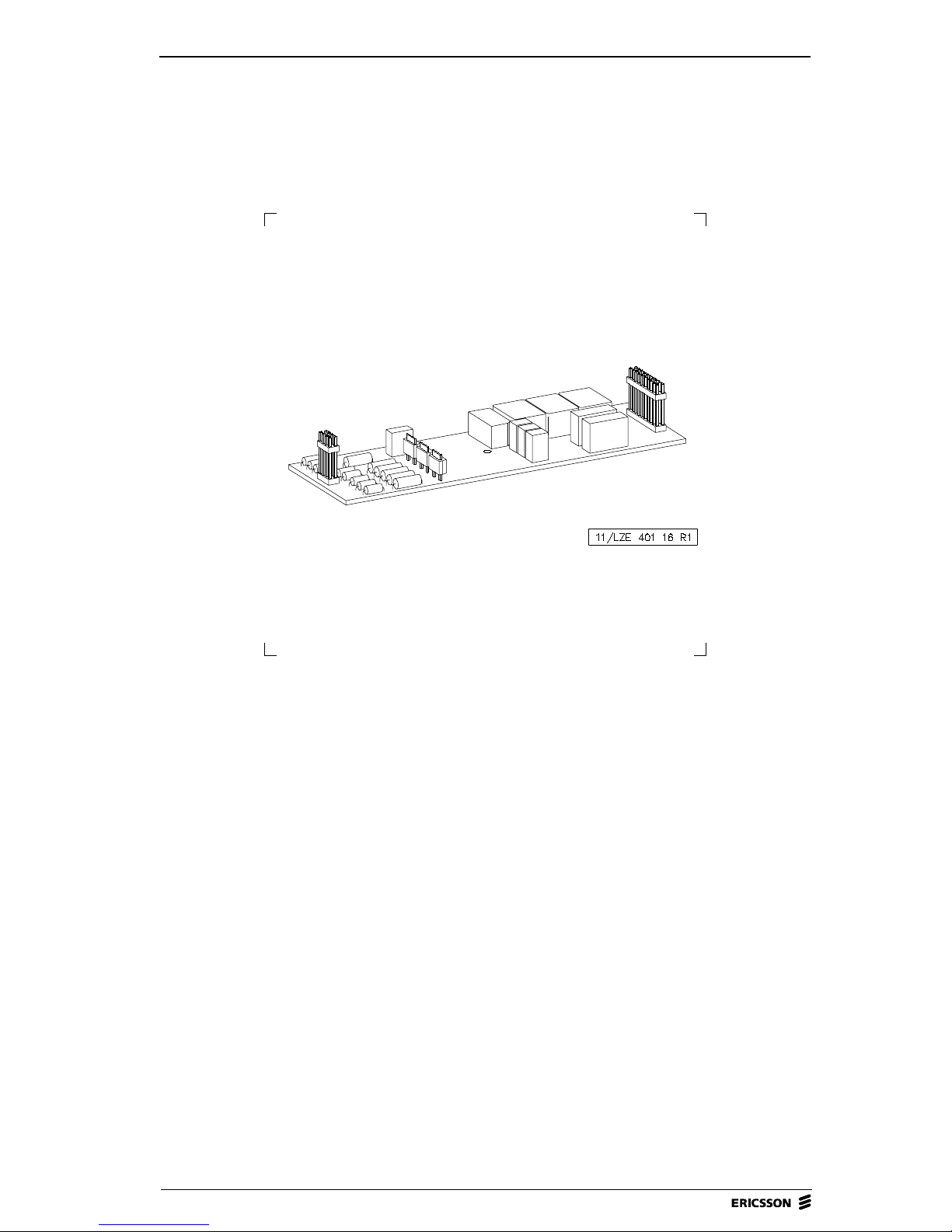
FE Adaptation Board (FAB)
Figure 6 FE Adaptation Board (FAB).
The FE Adaptation Board (FAB) includes two connectors, P1 and P2.
P1 2x10 pin header male connector with 0.1" module used for inter
connection to the FMB.
P2 2x4 pin header male con nector with 0.1" mod ule used for connecti on of
the various telephone lines.
BRU3 MANUAL, Doc.no: 1543-ANNA 805 08 Uen Rev H, 2003-06-10
Page 16
16 (60) BRU3 MANUAL
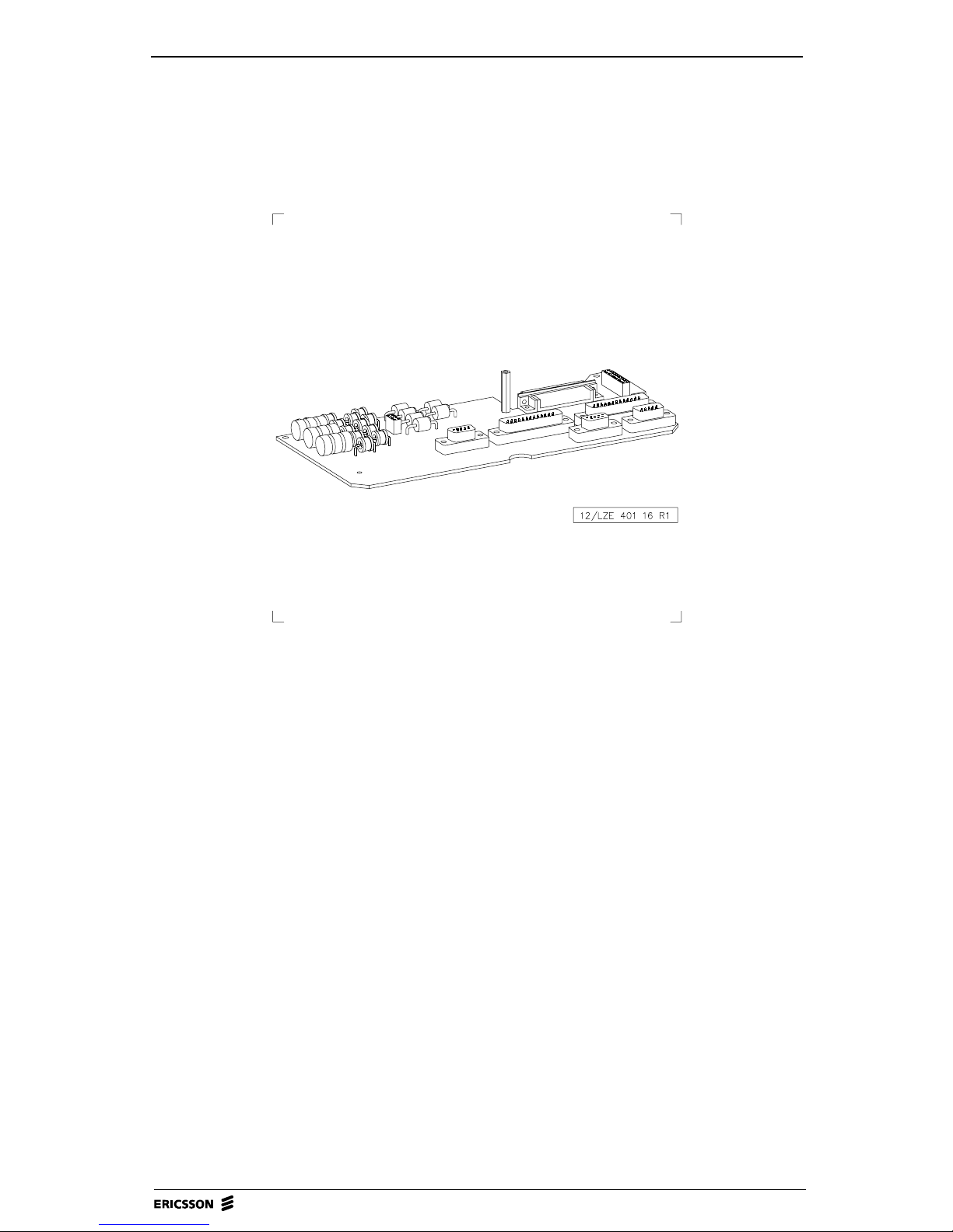
FE Connection Board (FNB)
Figure 7 FE Connection Board (FNB).
The FE Connection board ( FNB) includes conversio n circuits for V.1 1 and V.28
standards for the serial interfaces. It als o includes vo ltage pr otection and filters
for the modem, the V.11, the V.28 and the console ports.
The FNB contains the following connectors:
P1 9-pole D-SUB male, used for CONSOLE connection
P2 9-pole D-SUB female, used for alarm connections
P3 9-pole D-SUB female, used for connection of telephone lines
P4 (RS232-MOX) 25-pole D-SU B male , used for modem connect ion.
P5 (RS422-MOX) 25-pole D-SUB male used for modem connection.
BRU3 MANUAL, Doc.no: 1543-ANNA 805 08 Uen Rev H, 2003-06-10
Page 17
OPERATION AND MAINTENANCE, MODULE B1 17 (60)
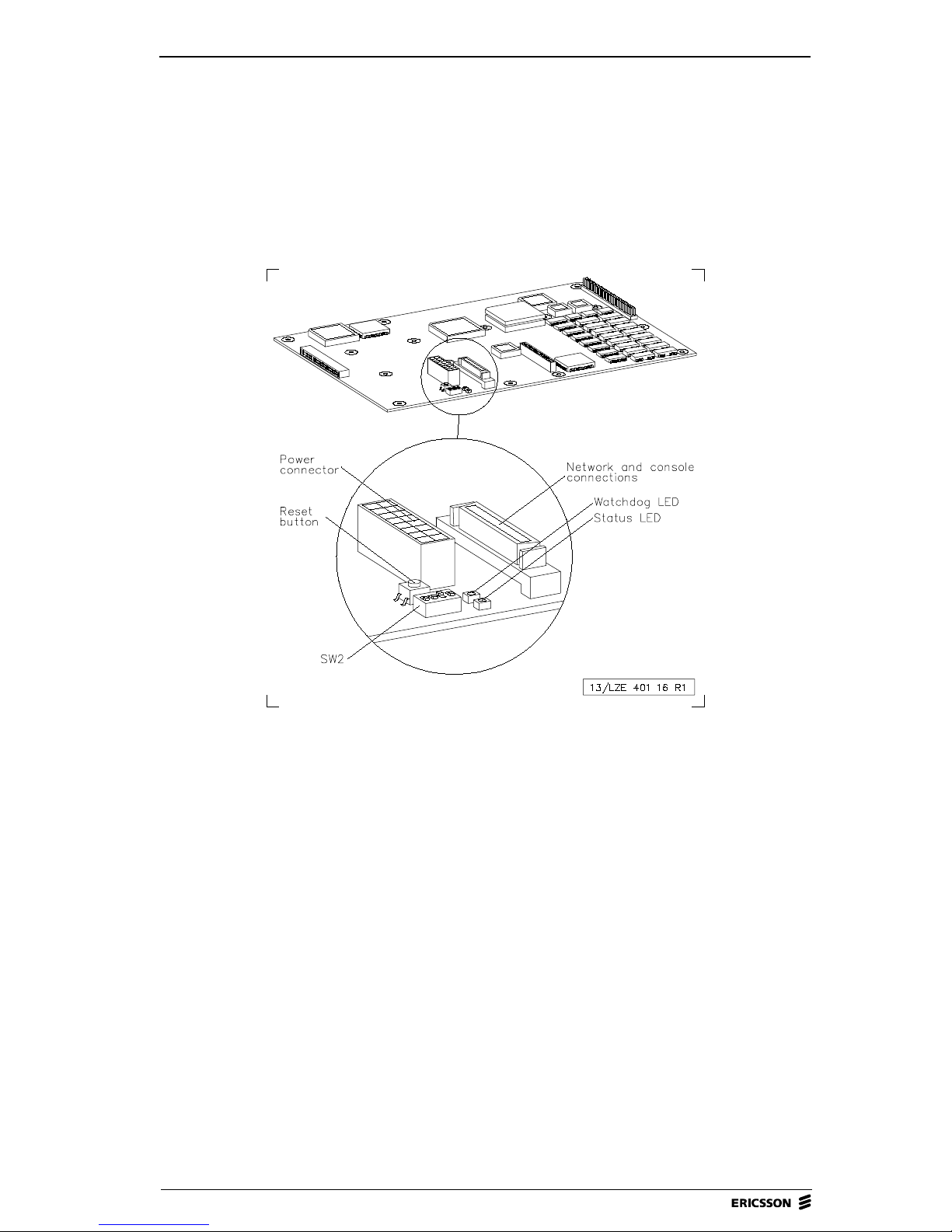
1.5 Logic Units
1.5.1 General
Figure 8 FE Computer Board (FCB).
1.5.2 Connections
The FE Computer Board incl udes two ports, A and B, for serial communication,
both handled by the integrated circuit Z16C35.
Network Connection (Port A)
Port A implies complete synchronous functionality, and also, limited modem
support. By the FNB and FMB, this port can be used for V.24/V.28, V.24/V.11
or V.24/V.32.
CONSOLE and NODOP Connection (Port B)
Port B is intended for using a CONSOLE and NODOP via the FNB with the
V.24 signals RX and TX.
BRU3 MANUAL, Doc.no: 1543-ANNA 805 08 Uen Rev H, 2003-06-10
Page 18

18 (60) BRU3 MANUAL
1.5.3 LEDs
LED Colour Function
Status indicator Yellow Lit when the processor is operating OK.
Watchdog alarm Red Lit when the Watchdog is released. If so, a
reset pulse is generated. The Watchdog LED is
lit and the signal WDSTATUS, read b y the
CPU, peaks.
1.5.4 Reset Button
To enable hardware reset of the FCB and the FMB (Modem Board), and also,
the FRB (FE Radio Board), the FCB is equipped with a reset button located next
to the LED Status indicator. To reach the b utton for a reset op eration, us e a pen
or a similar object.
A reset of the FCB may be generated for the following reasons:
1. Power-on reset: The reset is generated at power-on, and also, when a
power drop occurs.
2. Switch reset: The reset is activated when the reset button is pressed.
3. Watchdog reset. The reset is activated by th e watchdo g function if not
maintained.
4. CPU reset: The reset is performed by the CPU when a reset instruction is
executed. In this specific case no reset of the CPU itself is carried out.
BRU3 MANUAL, Doc.no: 1543-ANNA 805 08 Uen Rev H, 2003-06-10
Page 19

OPERATION AND MAINTENANCE, MODULE B1 19 (60)
1.6 Radio Units
1.6.1 General
The BRU3 is designed for du pl ex t raffic 8 kbit GMSK modul at ion on th e 400 ,
800 or 900 MHz band.
Figure 9 FE Radio Board (FRB) - 900 MHz.
Figure 10 FE Radio Board (FRB) - 800 MHz and 900 MHz.
21/2882-LZE 401 197 Rev A
BRU3 MANUAL, Doc.no: 1543-ANNA 805 08 Uen Rev H, 2003-06-10
Page 20

20 (60) BRU3 MANUAL
Figure 11 FE Radio Board (FRB) - 400 MHz.
TX
RX
Figure 12 FE Radio Board (FRB) - 400 MHz, ROA 117 8897
18/1424-LZE 401 204 A
BRU3 MANUAL, Doc.no: 1543-ANNA 805 08 Uen Rev H, 2003-06-10
Page 21

OPERATION AND MAINTENANCE, MODULE B1 21 (60)
1.6.2 Radio Operation
The BRU3 radio units are operated locally on site by using a portable PC and
FBTEST. By using FBTEST, it is possible to set TX and RX frequencies,
transmitter power, alarm levels, parameters, etc.
Selecting "Radio Operations" on the FBTEST Main menu makes it possible to
select between the following submenu alternatives:
1. TRANSCEIVER SETUP MENU
2. MEASUREMENT SETUP MENU
3. TRANSCEIVER CONTROL AND PRESENTATION MENU
4. CALIBRATION
5. RADIO REGISTER EDITOR
6. ADJUSTMENT
7. SETUP
For detailed information on radio operations, please refer to the FBTEST
Reference Manual.
1.6.3 Reset
To reset the FE Radio board, press the reset button on the FE Computer board
resetting both the computer board and radio board.
1.6.4 Connectors
1 connector: For antenna input cable (coaxial)
1 connector: For antenna output cable (coaxial)
For location, see Figure 9 through Figure 12.
BRU3 MANUAL, Doc.no: 1543-ANNA 805 08 Uen Rev H, 2003-06-10
Page 22

22 (60) BRU3 MANUAL
1.7 Power Supply
1.7.1 General
Figure 13 Power supply block diagram.
The BRU3 power supply parts are located in the FE Case bottom frame (FBF).
The power supply parts include the FE Power Supply Unit (FPU) and the FE
Battery Unit (FBU). The FE Heating Unit (FHU) located in the FE Case Top
Frame (FTF), is also regarded as a part of the power supply.
The power supply parts are to be used for:
• Uninterruptible power supply wi th distribution of 14V and 5V D C t o the
FCB and FRB
• Lightning protection
• Fused mains feed-through to the FHU.
BRU3 MANUAL, Doc.no: 1543-ANNA 805 08 Uen Rev H, 2003-06-10
Page 23

OPERATION AND MAINTENANCE, MODULE B1 23 (60)
1.7.2 FE Power Supply Unit (FPU)
Figure 14 FE Power Supply Unit (FPU).
1. 120 or 230V AC input
2. Power outlet to heater
3. Mains switch
4. Battery switch
5. Fuse 1, 6.3AT 250V
6. Fuse 2, 6.3AT 250V
7. Fuse 3, 6.3AF 250V
8. Mains, status indicator LED
9. 14V, status indicator LED
10. Error, alarm LED
The FE Power Supply Unit (FP U) di str ibutes powe r to t he mod em, lo gic, radio
and heating units.
To secure uninterrupted powe r functi on, a battery char ge check checks that the
batteries maintain the highest capacity possible. Failure due to low charging is
also reported to the FCB.
BRU3 MANUAL, Doc.no: 1543-ANNA 805 08 Uen Rev H, 2003-06-10
Page 24

24 (60) BRU3 MANUAL
Connectors
Connector Type To/From
MAINS INLET J1 120 or 230V AC pow er i nput to the FPU
POWER OUTLET
J2 120 or 230V AC pow er output to the FHU
TO HEATER
POWER OUTLET
INT . SUPPLY
J3 Power output to the FCB (5V and 14.7V) and pow er
input from the FBU (14. 7V )
Switches
Switch Function
MAINS SWITCH AC power supply on/off switch
BATTERY
SWITCH
Battery power supply on /o ff switch
BRU3 MANUAL, Doc.no: 1543-ANNA 805 08 Uen Rev H, 2003-06-10
Page 25

OPERATION AND MAINTENANCE, MODULE B1 25 (60)
LEDs
LED Colour Function
MAINS Ye llow Lit when incoming 120 or 230V AC power is OK.
+14V Yellow L it when +14V DC and +5V DC power distributio n to the radi o
unit and the DC/DC module is OK.
ERROR Red Sum alarm indicates a power failure in the FPU if one or more of
the following cau s es oc cur:
1. +14V and/ or +5V DC failure.
2. Charging cu rrent too low.
3. Fuse F3 is broken.
4. S1 - "ON", S2 - "OFF" and the battery is connected. NOTE!
This cause is not applicable for R3 or later FPU versions.
Note! The red "ERROR" LED will also be lit if the mains voltage is too
low and the battery is discharged.
Note! The red "ERROR" LED and the yellow "+14" LED will flicker if
the FPU is not correctly connected.
Fuses
Fuse Type Safety device for
F1 6.3AT 250V 6.3 AT 5x20 mm Mains input
F2 6.3AT 250V 6.3AT 5x20 mm
F3 6.3AF 250V 6.3AF 5x20 mm Power to/from the FBU
BRU3 MANUAL, Doc.no: 1543-ANNA 805 08 Uen Rev H, 2003-06-10
Page 26

26 (60) BRU3 MANUAL
1.7.3 FE Battery Unit (FBU)
Figure 15 FE Battery Unit (FBU).
The FE Battery Unit (FBU) is located in the case bottom frame. The FBU
includes a battery pack of 12 NiCd cells 1.2V 4Ah , wi th ext end ed t emperature
range. The battery pack is designed to withstand continuous charge.
The battery unit will start supp lying the BRU3 with power when the main po wer
supply goes below 90/198V. The unit is able to supply the BRU3 with power
for 30 minutes (39xx) and 15 minutes (34xx and 38xx) respectively.
A temperature sensor is included in the battery pack to ensure that the charging
current is not too strong when the temperature is high or low. The sensor is
connected to the charger in the FPU.
For information on how to perform a battery test, please refer to 2.4
Maintenance to be Performed in this section.
Connector
The FBU includes a 3-pin snap-in connector for connection to the FPU.
BRU3 MANUAL, Doc.no: 1543-ANNA 805 08 Uen Rev H, 2003-06-10
Page 27

OPERATION AND MAINTENANCE, MODULE B1 27 (60)
1.7.4 FE Heating Unit (FHU)
Figure 16 FE Heating Unit (FHU).
The FE Heating unit (FHU) is located in the FE Case Top Frame (FTF). The
FHU ensures that the temperature inside the BRU3 is within the requested
limits.
The unit consists of the FE Heating Board (FHB) including a heating regulator
and a overheating protection device.
When the temperature on the surface of the FTF is about 25 °C or lower, the
FHU starts heating the BRU3.
If the temperature should rise to about 55 °C, due to temperature regulating
failure, the overheating protection will cut of the power supply to the FHU.
Connectors
The FHU includes a 6-pin connector for incoming AC from the Power supply
unit.
BRU3 MANUAL, Doc.no: 1543-ANNA 805 08 Uen Rev H, 2003-06-10
Page 28

28 (60) BRU3 MANUAL
1.8 Alarms
The BRU3 includes the following hardware alarms:
Alarm Description
Temperature alarm HIGH Inside temp. exceeds +70 °C.
Temperature alarm LOW Inside temp. is below -20 °C.
Shut off Alarm signal indicates immediate BRU3 shut-off due to Temp.
alarm.
AC alarm Unspecified AC failure.
DC alarm Unspecified DC failure . Low or hi gh +14V or/and +5V.
Battery charge alarm Charge failure, low charging current.
Usual causes:
1. Battery switch off.
2. Battery fuse (No .3 ) broken.
3. Battery charger out of order.
4. Battery pack out of order.
Reflection alarm Output RF power/Voltage Standing Wave Ratio exceeding
alarm limit set.
Transmitter/Receiver alarm Unspecified Transmitter or Receiver failure.
Low output power alarm Output power below alarm limit set.
External alarm 1 For customer use.
Case alarm The alarm is used for checking that the BRU3 is closed, i.e. a
physical ac cess check.
For information regarding the setting of alarm limits, please refer to 1.7 Power
Supply in this section.
BRU3 MANUAL, Doc.no: 1543-ANNA 805 08 Uen Rev H, 2003-06-10
Page 29

OPERATION AND MAINTENANCE, MODULE B1 29 (60)
2 Maintenance
2.1 General
This section describes how to carry out scheduled, visual and preventive
maintenance on the BRU3 on site.
The scheduled, visual and preventive maintenance is carried out to increase the
operational reliability of the electrical and mechanical parts of the BRU3.
If running a Function Check on a BRU3 moun ted out door s, it is recommen ded
that the check be carried out under weather -protected conditions for the service
personnel and test equipment used.
If any problems occur while following the procedures in this section, please
refer to 3 Troubleshooting.
For 38xx and 39xx maintenance is carried out every:
• 6 Months (Radio Unit Reference Oscillator and Battery Test)
For 34xx maintenance is carried out every:
• 12 Months (Radio Unit Reference Oscillator)
• 6 Months (Battery Test)
Note! If the BRU3 has to be switched off, the shutdown procedure
described in 1.3 Start-Up and Shutdown Procedures, must be
followed before power-off is performed. If not, important data
may be lost and the subsequent start-up time may be significantly
increased.
BRU3 MANUAL, Doc.no: 1543-ANNA 805 08 Uen Rev H, 2003-06-10
Page 30

30 (60) BRU3 MANUAL
2.2 Equipment Required
To carry out maintenance on the BRU3 on site, the following equipment is
required:
• Portable PC including VT-100 emulation software
• FE Console Cable TSRA 902 0190 for connection of the PC to the BRU3
"P1-CONSOLE" port
• Frequency counter 1 GHz
Degree of accuracy: 0.01 ppm
• Set of screw drivers
• FBTEST software (normally installed in the BRU3)
2.3 Documentation Required
T o carry out maintenance on the BRU3 on site, the following documentation is
required:
• BRU3 Manual (the BRU3 modules in the
• Node SW - Operation and Maintenance module
• Node SW - Installation and Commissioning module
• BRU3 - Site documentation module
Note: The Site Documentation module is not included in the
electronically published version of the Mobitex NTE Client
Library but is delivered on paper together with the hardware.
Mobitex NTE Client Library)
BRU3 MANUAL, Doc.no: 1543-ANNA 805 08 Uen Rev H, 2003-06-10
Page 31

OPERATION AND MAINTENANCE, MODULE B1 31 (60)
2.4 Maintenance to be Performed
2.4.1 Visual and Preventive Maintenance
Radio Unit Reference Oscillator
In the BRU3, the reference oscillator checks the channel unit frequency. Thus,
adjustment check of the reference oscillator, in accordance with the following
procedure, implies check of the channel unit frequency accuracy.
Note! Only authorized personnel are allowed to adjust the frequency of
the reference oscillator.
Requirements
The measurement must be carried out on the correct carrier frequency for the
site.
The carrier wave must not have a freq uency error exceeding 0. 1 ppm (38xx and
39xx) or 0.2 ppm (34xx).
The reference oscillator must have been powered up at least 30 minutes before
the test is started.
Test equipment
• Portable PC including VT-100 emulation software
• FE Console Cable TSRA 902 0190
• FBTEST software
• Frequency counter 1 GHz (degree of accuracy: 0.01 ppm)
• RF attenuator 1 GHz, 30-50 dB.
BRU3 MANUAL, Doc.no: 1543-ANNA 805 08 Uen Rev H, 2003-06-10
Page 32

32 (60) BRU3 MANUAL
Test procedure
Note! To ca rry o ut the tes t and adjustment procedure, the BRU3 has to
be switched of f. Please refer to the shut down procedure described
in this section.
1. Connect the frequency counter via the RF attenuator to the BRU3 TX
ANT. connection.
2. Use FBTEST to set the correct transmitter carrier frequency for the site.
3. Select the power, which corresponds to -6 dB attenuation of the
transmitter.
4. Start the transmitter.
5. Read the frequency measured on the frequency co unter display. Check the
result against the requirements specified.
Adjustment
Use FBTEST for transmitter adjustment.
FE Computer Board (FCB)
• Check that the Watchdog alarm LED is not lit.
• Check that the CPU status indicator is lit (yellow light).
FE Power Supply Unit (FPU)
• Check that the sum alarm LED is not lit.
• Check that the AC and DC status indicator LEDs are lit (yellow light).
• Check the power cable and connector for damage. Replace if necessary.
BRU3 MANUAL, Doc.no: 1543-ANNA 805 08 Uen Rev H, 2003-06-10
Page 33

OPERATION AND MAINTENANCE, MODULE B1 33 (60)
2.4.2 Battery Test
Every 6 months, an d always be fore visiting a BRU3 site for regular
maintenance work, it is recommended to perform a battery test. The battery test,
which is described below, is executed from NODOP or from OM at the NCC.
Description
The Battery Test is performed by switching the node power supply to battery
power supply and measuring the time for the bat t ery t o g et di sch a rged below a
certain limit. When the limit is reached, the node power is switched back to
normal power supply and an alarm is sent to the NCC.
Requirements
The time for the battery test is defined by the operator.
Test procedure
1. Start the test by the OM/NODOP command ACTIVATE
BATTERY_TEST. The node power supply is switched to battery power
and the time for the batteries to get discharged is measured.
When the batteries are discharged, the node power is switched back to
normal power supply and an alarm is sent to the NCC.
2. Read the measured value on the display. The OM/NODOP command
SHOW BATTERY_ TES T presents the res ult of bo th the cu rren t, and last
completed, battery test.
Recommended:
39xx: 30 min. (15 min. for the 6W version)
34xx and 38xx: 15 min.
3. Check the result against the requirements specified.
4. Replace the battery unit, if necessary.
Note! The battery should be in operati on for at least 6 0 hou rs befo re an
initial battery test may be performed for the first time after powerup.
BRU3 MANUAL, Doc.no: 1543-ANNA 805 08 Uen Rev H, 2003-06-10
Page 34

34 (60) BRU3 MANUAL
A battery test cannot be started under the following conditions:
• A battery test is already running
• The temperature inside the BRU3 is not within the range 20-40 °C
• The batteries are already discharged
• The Node bac k-up time i s out of range.
2.5 Function Check
2.5.1 General
In addition to the regular Check and Visual and Preventive Maintenance
program previously described, a Function Check, whi ch is descri bed below,
may be performed if so requested by the operator.
The Function Check includes checking BRU3 boards, transmitter, receiver,
antennas and hardware alarms.
Furthermore, the Function Check may be used as an extended hardware
commissioning test as a complement to the hardware comm issioning procedur e
previously described in this manual.
2.5.2 Equipment Required
To carry out the Function Check, the following equipment is required:
•Power meter
• Multimeter
• Ericsson test modem LPBA 109 08 or RF signal generator 1 GHz with a
built-in GMSK-modulator
• 1 pc of Radio Communication test set, including
- RF signal generator 1GHz, with external FM DC input
- Modulation Meter.
BRU3 MANUAL, Doc.no: 1543-ANNA 805 08 Uen Rev H, 2003-06-10
Page 35

OPERATION AND MAINTENANCE, MODULE B1 35 (60)
2.5.3 Check of Internal Power Supply (Mains and Battery)
Check of internal power supply
Requirements
The required value of the internal power supply should be:
with mains supply:
5V ±0.2V, 8V ±0.5V and 14.7V ±0.3V.
with Battery supply:
5V ±0.2V, 8V ±0.5V and 14.1V ±0.3V, using fully ch arged batteries.
Test equipment
• Voltmeter
Test procedure (Mains supply)
1. Set the Main switch to position "1". Make sure that the yellow LEDs,
MAINS and +14V, are lit.
2. Measure the voltage in the FCB measure points marked "+14V", "+5V"
and "+8V".
3. Read the value measured on the vo ltmeter display . Check the result against
the requirements specified.
Test procedure (Battery supply)
1. Make sure that the "BATTERY SWITCH" on the FPU is in position "1".
The yellow LED indicating "14V" on the FPU should be lit.
2. Set the "MAINS SWITCH" on the Power supply unit to position "0".
Make sure the yellow LED "MAINS" is not lit.
3. Measure the voltage in the FCB measure points marked "+14V", "+5V"
and "+8V".
4. Read the value measured on the vo ltmeter display . Check the result against
the requirements specified.
BRU3 MANUAL, Doc.no: 1543-ANNA 805 08 Uen Rev H, 2003-06-10
Page 36

36 (60) BRU3 MANUAL
Figure 17 Measurement points on FCB.
BRU3 MANUAL, Doc.no: 1543-ANNA 805 08 Uen Rev H, 2003-06-10
Page 37

OPERATION AND MAINTENANCE, MODULE B1 37 (60)
2.5.4 FBTEST Board Test
Check of BRU3 boards
Requirements
It is required that a Medium b oard test of all BRU3 bo ards should be carried out
before taking the BRU3 into operation. No errors are accepted.
Test equipment
• Portable PC including VT-100 emulation software
• FE Console Cable TSRA 902 0190
• FBTEST software.
Test procedure
1. Use FBTEST to set up two test cycles.
2. Run the test cycles.
3. Read the result on the terminal display. Check the result against the
requirements specified.
BRU3 MANUAL, Doc.no: 1543-ANNA 805 08 Uen Rev H, 2003-06-10
Page 38

38 (60) BRU3 MANUAL
2.5.5 Channel Unit Output Power
Check of the transmitter channel unit output power
Requirements
The nominal output power differs depending on the BRU3 version purchased.
For tolerances, please refer to the tables below:
900 MHz, 3W version:
Power
900 MHz
3.0W 0 1.5 1.5
1.5W -3 1.5 1.5
800mW -6 1.5 1.5
400mW -9 1.5 1.5
200mW -12 1.5 1.5
100mW -15 2.0 3.0
50mW -18 2.0 3.0
25mW -21 2.0 3.0
Attenuation (dB) Tolerance (+dB) Tolerance (-dB)
Measurements must carried out on the correct carrier frequency for the 39xx.
BRU3 MANUAL, Doc.no: 1543-ANNA 805 08 Uen Rev H, 2003-06-10
Page 39

OPERATION AND MAINTENANCE, MODULE B1 39 (60)
800 MHz, and 900 MHz, 6W version:
Power
800 MHz
6.0W 0 1.5 1.5
3.0W -3 1.5 1.5
1.5W -6 1.5 1.5
800mW -9 1.5 1.5
400mW -12 1.5 1.5
200mW -15 2.0 3.0
100mW -18 2.0 3.0
50mW -21 3.0 3.0
Attenuation (dB) Tolerance (+dB) Tolerance (-dB)
Measurements must carried out on the correct carrier frequency for the 38xx.
400 MHz:
Power
400 MHz
6.0W 0 1.5 1.5
3.0W -3 1.5 1.5
1.5W -6 1.5 1.5
800mW -9 1.5 1.5
400mW -12 1.5 1.5
200mW -15 2.0 3.0
100mW -18 2.0 3.0
50mW -21 2.0 3.0
Attenuation (dB) Tolerance (+dB) Tolerance (-dB)
Measurements must be carried out on the correct carrier frequency for the 34xx.
BRU3 MANUAL, Doc.no: 1543-ANNA 805 08 Uen Rev H, 2003-06-10
Page 40

40 (60) BRU3 MANUAL
Test equipment
• Portable PC including VT-100 emulation software
• FE Console Cable TSRA 902 0190
• FBTEST software
• Output powe r meter
39xx, 3W version: 20 mW - 5W
38xx, and 39xx, 6W version: 50 mW - 10W
34xx: 50 mW - 10W
Degree of accuracy: better than ±0.5 dB
• Coaxial cable.
Test procedure
1. Connect the output power meter to the BRU3 antenna connection.
2. Use FBTEST to set the correct transmitter carrier frequency for the site.
3. Use FBTEST to select the desired power level.
4. Start the transmitter.
5. Read the power measured on the output power meter display. Check the
result against the requirements specified.
6. Select a new power level and repeat the measurement procedure.
Note! The adjustment of output power is no rmally carried out via NCC.
BRU3 MANUAL, Doc.no: 1543-ANNA 805 08 Uen Rev H, 2003-06-10
Page 41

OPERATION AND MAINTENANCE, MODULE B1 41 (60)
2.5.6 Transmitter Deviation
Check of transmitter frequency deviation
Requirements
The sine wave 1 kHz shall give the frequency deviation of ±2.0 kHz + 5.0%.
The measurements must be carried out on the correct carrier frequency for the
site.
Test equipment
• Portable PC including VT-100 emulation software
• FE Console Cable TSRA 902 0190
• FBTEST software
• Deviation meter 900 MHz, 800 MHz or 400 MHz
Degree of accuracy: better than ±3.0%.
Test procedure
1. Connect the deviation meter to the BRU3 TX ANT. connection.
2. Use FBTEST to set the correct transmitter carrier frequency for the site.
3. Select the power level which corresponds to -6 dB attenuation of the
transmitter.
4. Select modulation test sequence.
5. Start the transmitter.
6. Read the deviation frequency measured on the deviation meter display.
Check the result against the requirements specified.
BRU3 MANUAL, Doc.no: 1543-ANNA 805 08 Uen Rev H, 2003-06-10
Page 42

42 (60) BRU3 MANUAL
2.5.7 Bit Errors at high Signal Levels
Check of the bit error rate at high signal levels
Requirements
The measurement should be carried out within a time period of 60 seconds. The
RF signal level to the receiver should be -81 dBm. The tolerated failure rate
during the test period is set to 0 or 1 error . The mea surement should be repeated
with a RF signal of -11 dBm. The above measurements must be carried out on
the correct carrier frequency for the site.
Test equipment
• Portable PC including VT-100 emulation software
• FE Console Cable TSRA 902 0190
• FBTEST software
• Alternative 1 or 2 described below.
Alternative 1
• Ericsson test modem LPBA 109 08
• R F signal generator 1 GHz. The RF signal generator must include an input
for external modulation with a lower limiting frequency of 0 Hz. The
frequency must be able to modulate with DC voltage. Degree of frequency
accuracy: 0.01 ppm. The RF output signal level must be adjust able between
-123 dBm and -3 dBm.
Accuracy: Better than 1 dB.
Alternative 2
• RF signal generat or 1 GHz with a bu ilt-in GMS K-modulator. The generator
must be able to generate the 511 bit PRBS signal used when measuring the
bit error rate. (Using this alternative excludes the Ericsson test modem
specified above.)
Accuracy: Better than 1 dB.
BRU3 MANUAL, Doc.no: 1543-ANNA 805 08 Uen Rev H, 2003-06-10
Page 43

OPERATION AND MAINTENANCE, MODULE B1 43 (60)
Test procedure
1. Connect the signal generator to the BRU3 antenna connection.
2. Use FBTEST to set the receiver channel number corresponding to the
correct carrier frequency.
3. Set the signal generator’s carrier frequency to the receiver’s nominal
carrier frequency.
The GMSK modem supplies the RF signal generator with an analog
pseudo-random signal which matches the test signal M2. This signal
modulates the RF signal generator. (In case the RF signal generator is
equipped with a built-in GMSK modem the external GMSK modem is
excluded.) The receiver demodulated signal BER, is calculated by the
BRU3 logic.
4. Start the bit error measurement using FBTEST.
5. Adjust the RF signal level sent to the receiver to -81 dBm. Check the bit
error rate during a period of three minutes.
6. Check the result against the requirements specified.
7. Set a new (- 1 1 dB) R F signal leve l on the sig nal generator and t he BRU3,
and repeat the measurement procedure.
BRU3 MANUAL, Doc.no: 1543-ANNA 805 08 Uen Rev H, 2003-06-10
Page 44

44 (60) BRU3 MANUAL
2.5.8 Receiver Sensitivity
Check of the receiver sensitivity
Requirements
The receiver sensitivity is defined as the RF level on the receiver antenna
connection which generates a BER value of 1%. The RF signal sent to the
receiver should be mo dulated with the M2 test s ignal with a frequency devi ation
of ±2.00 kHz. At 1% BER, the sign al level to the receiver s hould be -1 1 7 dBm,
or better. At a signal level of -107 dBm to the receiver antenna conn ection, the
BER value should be better than 0.01%.
The above measurements must be carried out on the correct carrier frequency
for the site.
Test equipment
• Portable PC including VT-100 emulation software
• FE Console Cable TSRA 902 0190
• FBTEST software
• Alternative 1 or 2 described below.
Alternative 1:
• Ericsson test modem LPBA 109 08
• R F signal generator 1 GHz. The RF signal generator must include an input
for external modulation with a lower limiting frequency of 0 Hz. The
frequency must be able to modulate with DC voltage. Degree of frequency
accuracy: 0.01 ppm. The RF output signal level must be adjust able between
-123 dBm and -3 dBm.
Accuracy: Better than 1 dB.
Alternative 2:
• RF signal generator 1 GHz with a built-in GMSK modulator . The generator
must be able to generate the 511 bit PRBS signal used when measuring bit
errors. (Using this alternative excludes the Ericsson test modem specified
above.
Accuracy: Better than 1 dB.)
BRU3 MANUAL, Doc.no: 1543-ANNA 805 08 Uen Rev H, 2003-06-10
Page 45

OPERATION AND MAINTENANCE, MODULE B1 45 (60)
Test procedure
1. Connect the signal generator to the BRU3 TX ANT. connection.
2. Use FBTEST to set the receiver channel number corresponding to the
correct carrier frequency.
3. Set the signal generator’s carrier frequency to the receiver’s nominal
carrier frequency.
The GMSK modem supplies the RF signal generator with an analog
pseudo random sig nal match ing t he test signal M2 . This s ignal modulat es
the RF signal generator . ( In case the RF signal g enerator is equipp ed with
a built-in GMSK modem the external GMSK modem is excluded.) The
receiver-demodulated signal BER, is calculated by the BRU3 logic.
4. Start the bit error measurement using FBTEST.
5. Adjust the RF signal level sent to the receiver until the BER value is
stabilized to 1.0%
6. Check the result against the requirements specified.
7. Repeat the measurement procedure and adjust the RF signal level sent to
the receiver until the BER value is stabilized to 0.01%.
BRU3 MANUAL, Doc.no: 1543-ANNA 805 08 Uen Rev H, 2003-06-10
Page 46

46 (60) BRU3 MANUAL
2.5.9 Receiver Sensitivity at Frequency Deviation
Check of the receiver sensitivity when the incoming RF signal deviates
from the requirements specified
Requirements
The RF signal sent to the receiver must be modulated with the M2 test signal.
The frequency deviation should rate 95% of the normal deviation, ±1. 90 kHz.
The RF signal frequency offset should be 1.45 kHz. The measurement should
be performed w ith both pos itive and n egative of fset on the centre frequency. At
1% BER, the RF signal level sent to the receiver should be -114 dBm, or better .
The above measurements must be carried out on the frequencies listed under
Measurement Frequencies in the Introduction and Product Specification
section of the BRU3 - General module.
Test equipment
• Portable PC including VT-100 emulation software
• FE Console Cable TSRA 902 0190
• FBTEST software
• Alternative 1 or 2 described below.
Alternative 1:
• Ericsson test modem LPBA 109 08
• R F signal generator 1 GHz. The RF signal generator must include an input
for external modulation with a lower limiting frequency of 0 Hz. The
frequency must be able t o mo dulat e wi th DC- vol ta ge. De gree o f fr equen cy
accuracy: 0.01 ppm. The RF output signal level must be adjust able between
- 10 dBµV emf and + 110 dBµV emf.
Accuracy: Better than 1 dB.
Alternative 2:
• RF signal generator 1G Hz wit h a built-in GMSK-modul ator. The generator
must be able to generate the 511 bit PRBS signal used when measuring bit
errors. (Using this alternative exclu des the n eed of the Ericsson test m odem
specified above.)
Accuracy: Better than 1 dB.
BRU3 MANUAL, Doc.no: 1543-ANNA 805 08 Uen Rev H, 2003-06-10
Page 47

OPERATION AND MAINTENANCE, MODULE B1 47 (60)
Test procedure
1. Connect the signal generator to the BRU3 TX ANT. connection.
2. Use FBTEST to set the receiver channel number corresponding to the
correct carrier frequency.
3. Set the signal generator’s carrier frequency to the receiver’s nominal
carrier frequency, including offset.
The GMSK modem supplies the RF signal generator with an analog
pseudo-random signal that matches the test signal M2. This signal
modulates the RF signal generator. (In case the RF signal generator is
equipped with a built-in GMSK modem, the external GMSK modem is
excluded.) The receiver demodulated signal BER, is calculated by the
BRU3 logic.
4. Start the bit error measurement using FBTEST.
5. Adjust the RF signal level sent to the receiver until the BER value is
stabilized to 1.0%
6. Check the result against the requirements specified.
7. Set a new receiver frequency on the signal generator and the BRU3, and
repeat the measurement procedure.
BRU3 MANUAL, Doc.no: 1543-ANNA 805 08 Uen Rev H, 2003-06-10
Page 48

48 (60) BRU3 MANUAL
2.5.10 Antenna input Signal
Check of the receiver signal strength level
Requirements
The RF signal gener ator must be unmo dulated. Measurement ran ge: -113 dBm
to -53 dBm, in steps of 10dB. The measured accuracy on the RSSI-signal may
deviate by up to ±5dB. The above measurement must be carried out on the
correct carrier frequency for the site.
Test equipment
• Portable PC including VT-100 emulation software
• FE Console Cable TSRA 902 0190
• FBTEST software
• RF signal generator 1 GHz. Degree of frequency accuracy: 0.01 ppm. The
RF output signal level must be adjustable between -123 dBm and -3 dBm,
with an accuracy of ±1dB.
Test procedure
Note! The transmitter has to be switched off before starting the test
procedure is started.
1. Connect the signal generator to the BRU3 RX ANT. connection.
2. Use FBTEST to set the receiver channel number corresponding to the
correct carrier wave frequency.
3. Set the signal generator’ s carrier wave frequency to the receiver’ s nominal
carrier wave frequency. The signal generator carrier wave must be
modulated.
4. Change the RF signal g enerato r out put level throu ghout the mea surement
range in steps of 10 dB.
5. Check the result against the requirements specified.
BRU3 MANUAL, Doc.no: 1543-ANNA 805 08 Uen Rev H, 2003-06-10
Page 49

OPERATION AND MAINTENANCE, MODULE B1 49 (60)
2.5.11 Transmitter Antenna VSWR
Check of the Voltage Standing Wave Ratio (VSWR).
Requirements
The power level must be set to a level corresponding to a feeder loss (Lf) of 0
dB, i.e., maximum output power. At maximum output power the required
VSWR value should be < 2.0.
The measurement of the VSWR value should be carried out on the frequency
for the site. It is important to use an external power meter. The internal power
meter is only intended t o give an indication of the VSW R valu e and to make it
possible to generate an alarm when a conf igurable level has been exceeded. The
absolute accuracy of the internal power meter depends on the an tenna and cable
configuration.
The VSWR values measured at the antenna connector must be adjusted to the
feeder loss of the installation according to the table below.
Feeder Loss,
Lf [dB]
0 < 2.0 > 10 3.5 5
1 < 1.7 > 12 2.6 7
2 < 1.5 > 14 2.1 9
Required
VSWR
Required
Return Loss,
PF-PR [dB]
VSWR
Alarm
Level
Return Loss
Alarm Level
[dB]
Note! The VSWR alarm levels are the recommended values. The
individual settings for each BRU3 is decided by the operator.
BRU3 MANUAL, Doc.no: 1543-ANNA 805 08 Uen Rev H, 2003-06-10
Page 50

50 (60) BRU3 MANUAL
Test equipment
• Portable PC including VT-100 emulation software
• FE Console Cable TSRA 902 0190
• FBTEST software
•External Power Meter
Test procedure
1. Connect the transmitter antenna feeder to the external power meter and
then the power meter via cable (RG 214 ) to th e Tx Antenna conn ector o n
the FNB.
2. On request, enter !!! and set the virtual thumb wheel to position 7.
3. Use FBTEST to set the transmitter channel number corresponding to the
correct carrier frequency.
4. Turn on the transmitter output power by means of FBTEST.
5. Measure the PF and PR value using the external power meter.
6. Calculate the VSWR value by using the following formula, or the
nomogram in Figure 18.
VSWR = (x + 1)/(x - 1), x = 10E((PF - PR)/20)
For example if VSWR = 1.5, then PF - PR = 14 dB.
7. Estimate the total feeder loss of the installation and use the corresponding
row in the table above to check tha t the measured VSWR value (received
from the nomogram in Figur e 18 or the formula above) complies with the
required VSWR val ue.
8. Note the feeder loss, the measured VSWR value and the corresponding
VSWR alarm level in the Commissioning T est Record. The VSWR alarm
level shall be set using NETREG in NCC.
9. Turn off the transmitter output power by means of FBTEST.
BRU3 MANUAL, Doc.no: 1543-ANNA 805 08 Uen Rev H, 2003-06-10
Page 51

35
30
25
20
15
10
Return Loss [dB], (PF - PR)
5
OPERATION AND MAINTENANCE, MODULE B1 51 (60)
0
1 1,1 1,2 1,3 1,4 1,5 1,6 1,7 1,8 1,9 2
VSWR
Figure 18 VSWR nomogram.
BRU3 MANUAL, Doc.no: 1543-ANNA 805 08 Uen Rev H, 2003-06-10
Page 52

52 (60) BRU3 MANUAL
2.5.12 Hardware Alarm Status
Check of alarm status in BRU3
Requirements
All alarms shall be in NORMAL mode, defined as follows:
Alarm Status
EXT_ALM1 (External Alarm 1)
INACTIVE (ON) CASE_ALM
(Open Case Alarm) INACTIVE (OFF)
LOWTMP (Temperature Alarm LOW)
INACTIVE (OFF) HIGHTMP
(T em peratu re Alarm HIGH) INACTIVE (OFF)
CHERR (Battery Charge Ala rm)
INACTIVE (OFF) DCERR
(DC Alarm) INACTIVE (OFF)
ACERR (AC Alarm)
INACTIVE (OFF) TxRxError
(Transmitter/Receiver Fault Alarm) INACTIVE (N)
VSWR (Reflection Alarm)
INACTIVE (N) Low Tx power
(Low Output Power Alarm) INACTIVE (N)
Test equipment
• Portable PC including VT-100 emulation software
• FE Console Cable TSRA 902 0190
• FBTEST software.
BRU3 MANUAL, Doc.no: 1543-ANNA 805 08 Uen Rev H, 2003-06-10
Page 53

OPERATION AND MAINTENANCE, MODULE B1 53 (60)
Test procedure
1. Select "STATUS OVERVIEW" on the Main Menu.
2. Read the alarm status obtained on the terminal screen. Check the result
against the requirements specified.
BRU3 MANUAL, Doc.no: 1543-ANNA 805 08 Uen Rev H, 2003-06-10
Page 54

54 (60) BRU3 MANUAL
3 Troubleshooting
3.1 General
This section provides information on the measures to be taken if errors should
be found in the BRU3. The section describes the measures to be taken on site.
Most of the measures carried out durin g troubleshoo ting generate alarms at the
NCC, and also, will effect the node’s function. Therefore, the NCC operator
shall always be consulted before any measure is carried out on site.
The service personnel must be familiar with the BRU3 units before using this
section. For information about each unit, please refer to 1 Design, Function
and Operation in this section.
In most cases, faults are caused by units not working properly, or switches set
to invalid positions.
Should the instructions herein not sufficiently provi de the req uested help in
order to locate and/or r emedy the error, please contact your local Field Support
Centre (FSC).
For information regarding how to trouble-shoot software errors, please refer to
the Node Software User's Guide in the Node SW - Operati on and Maintenan ce
module.
Note! If the BRU3 has to be switched off, the shutdown procedure
described in 1.3 Start-Up and Shutdown Procedures, must be
followed before power off is performed. If not, important data
may be lost and the subs equent start-up time may be sig nificantly
increased.
BRU3 MANUAL, Doc.no: 1543-ANNA 805 08 Uen Rev H, 2003-06-10
Page 55

OPERATION AND MAINTENANCE, MODULE B1 55 (60)
3.2 Power Supply Units
3.2.1 FE Power Supply Unit (FPU)
Indication: "MAINS" LED* is not lit.
Possible cause Action
MAINS SWITCH set to "0". Set MAINS SW IT CH to "1".
Fuse(s) F1-F2 defective. Replace fuse(s).
Incoming power cable/ connector
defective.
Incoming AC powe r fai lure. Check site AC power distribution.
FPB defective. Replace FPU if necessary.
Replace incoming power cable/connector.
* Is lit when incoming 120/230V AC power is OK.
Indication: "14V" LED** is not lit.
Possible cause Action
Fuse(s) F1-F3 defective. Replace fuse(s).
Cable/connecto rs bet w e en FPU
and FBU defect ive or not
connected to the FCB.
Low power in Ba tt ery pack. Check Battery pack pow er level. Recharg e th e Ba ttery.
Replace cable/c onne ctors.
** Is lit when the 14V DC power distribution to th e radio un it and th e D C/DC
module is OK.
BRU3 MANUAL, Doc.no: 1543-ANNA 805 08 Uen Rev H, 2003-06-10
Page 56

56 (60) BRU3 MANUAL
Indication: "ERROR" LED* is lit.
Possible cause Action
Fuse(s) F1-F3 defective. Replace fuse(s).
Cable/connect ors between FPU
and FBU defectiv e or not
connected to the FCB.
FPB defective. Replace the BRU3 if necessary.
Check cable/c onnectors. Replace if ne cessary.
* Indicates an unspecified power or charger failure in the FE Power Supply Unit
(FPU).
3.2.2 FE Battery Unit (FBU)
The FE Battery Unit (FBU) does not include LEDs for alarm or status
indication. For troubleshooting the FBU, please refer to 3.2.1 FE Power Supply
Unit (FPU) in this section.
BRU3 MANUAL, Doc.no: 1543-ANNA 805 08 Uen Rev H, 2003-06-10
Page 57

OPERATION AND MAINTENANCE, MODULE B1 57 (60)
3.3 Logic and modem units
3.3.1 FE Computer Board (FCB)
Indication: STATUS indicator LED* is not lit.
Possible cause Action
Power failure. Check power distribution on FCB , m e asure point "5V".
Reset BRU3 via FCB reset butto n:
1) If BRU3 starts, run FBTEST Board Test for further
check.
2) If BRU3 does not start, repla ce the BRU3.
FCB defective. Run FBTEST Board Test, (please refer to the FBTEST
Reference Manual).
Replace the BRU3 if FCB is found to be defect iv e.
* Is lit when the processor is operating normally.
Indicati on: WATCHDOG ala r m LED** is lit.
Possible cause Action
Hardware fault on FCB . Run FBTEST Board Test, (please refer to the FBTEST
Reference Manual).
If FCB is found to be defective, replace the BRU3.
Software error. Con tact your local Field Support Centre (FSC ) for
further assistance.
** The Watchdog is released.
BRU3 MANUAL, Doc.no: 1543-ANNA 805 08 Uen Rev H, 2003-06-10
Page 58

58 (60) BRU3 MANUAL
3.3.2 FE Modem Board (FMB) & FE Adaptation Board (FAB)
Note! The FE Modem Board and the FE Adaptation Board do not
include LEDs for alarm or status indication.
Indication: Modem out of order or working improperly.
Possible cause Action
Incorrect modem se tup in
FBTEST.
Incorrect dip switch settin g on
FCB.
Cables/Connect ors not properly
connected.
FMB or FAB defective. Run FBTEST Board Test. Replace FE Case Top Frame
Check modem setup in FBT EST Modem menu.
Check dip switch (SW 2) set ti ng on FCB.
Check cables /c onnectors. Replace if ne cessary.
if FMB is found to be de fective.
Replace BRU3 comp lete if FAB is found to be
defective.
3.3.3 FE Connection Board (FNB)
Note! The FNB does not include LEDs for alarm or status indication.
Indication: Connections/connectors defective.
Possible cause Action
FNB defective. Run FBTEST Board Test. To run extended FNB test,
plugs must be adapted to the RS422 and RS232
connections on FN B.
Replace BRU3 comple te if FNB is fo und to be
defective.
BRU3 MANUAL, Doc.no: 1543-ANNA 805 08 Uen Rev H, 2003-06-10
Page 59

OPERATION AND MAINTENANCE, MODULE B1 59 (60)
3.4 Radio units
3.4.1 FE Radio Board (FRB)
Note! The FRB does not include LEDs for alarm or status indication.
Indication: Radio units out of order or wor k ing improperly.
Possible cause Action
FRB defective. Run FBTEST Board Test including FCB. Replace FE
Case Top Frame if FRB or FCB is found to be
defective.
If no fault is found, please refer to 2.5 Function Check
in this section, describing a number of radio tests
possible to perform by using FBTEST.
Replace the BRU3 if necessary.
Antenna cables or c onnections
defective.
Check ante nna cables and conn ections. Repl ace if
necessary.
3.5 FE Heating Unit (FHU)
3.5.1 FE Heating Board (FHB)
Note! The FHB does not include LEDs for alarm or status indication.
Indication: Heat ing unit out of order or working improperly.
Possible cause Action
Low temperature inside the
BRU3.
No power distributi on to FHU. Chec k FH U connectio n to FPU. Replac e c on nector if
Check the heating unit (probably out of order). Repla ce
the BRU3.
necessary.
BRU3 MANUAL, Doc.no: 1543-ANNA 805 08 Uen Rev H, 2003-06-10
Page 60

60 (60) BRU3 MANUAL
BRU3 MANUAL, Doc.no: 1543-ANNA 805 08 Uen Rev H, 2003-06-10
 Loading...