

Page 1
INSTALLATION INSTRUCTION
Prepared
SEA/EBMP Stangelberger
Doc respons/Approved Checked
Subject responsible
SEA/EBAX/F
SEA/EBMP ASB 150 02
Documentnumber
1531-BDV BS 101 01 Uen
Date
Rev
1998-05-29 L
Database reference
Reference
1531-BDVBS10101Uen-1-L.emf
INSTALLATION INSTRUCTION
EXCHANGE CABINET
BDV BS 101 01
1(46)
businessphone
Page 2

INSTALLATION INSTRUCTION
Subject responsible
DocumentnumberPrepared
1531-BDV BS 101 01 Uen
Doc respons/Approved Checked Reference
Date Rev
1998-05-29
L
3(46)
Contents Page
1 GENERAL . . . . . . . . . . . . . . . . . . . . 4
1.1 Supplementary documents. . . . . . . . 4
1.2 Tools . . . . . . . . . . . . . . . . . . . . . . . . . 4
2 DECLARATION OF
CONFORMITY . . . . . . . . . . . . . . . . . 5
3 HOW TO OPEN THE CABINET. . . . 7
4 INSTALLATION . . . . . . . . . . . . . . . . 7
4.1 Mounting of the cabinet . . . . . . . . . . 7
4.2 Safety and EMC . . . . . . . . . . . . . . . . 8
4.3 Access to the boards . . . . . . . . . . . . 8
5 POWER SUPPLY UNIT . . . . . . . . . . 9
5.1 Replacement of the power
supply unit . . . . . . . . . . . . . . . . . . . . 9
5.2 Power feeding with an external
DC supply. . . . . . . . . . . . . . . . . . . . 10
6 ALLOCATION . . . . . . . . . . . . . . . . 10
Contents Page
7 INTEGRATED CORDLESS. . . . . . 28
7.1 Board Descriptions . . . . . . . . . . . . 28
7.2 Traffic capacity. . . . . . . . . . . . . . . . 28
7.3 IC-CU2 (GAP-Protocol) . . . . . . . . . 30
7.4 Base Station (KRCNB 201 03/_
and KRCNB 301 01/_). . . . . . . . . . 31
8 LINE NETWORK. . . . . . . . . . . . . . 39
8.1 Cables for BDV 113 08 . . . . . . . . . 40
9 MARKING OF CABLES . . . . . . . . 44
10 INTERNAL MDF
(Main Distribution Frame) . . . . . . 44
11 Door Interface Unit
(BFY BS 10101/1) . . . . . . . . . . . . . 45
12 INSTALLATION OF ALARM
INTERFACE UNIT . . . . . . . . . . . . . 46
6.1 Power supervision of ELU-A. . . . . . 10
6.2 Connection of CM-Boards . . . . . . . 11
6.3 System Power Consumption. . . . . . 11
6.4 BTU-A and BTU-A2 13
6.5 Power failure circuit (PFC) . . . . . . . 13
6.6 BTU-C. . . . . . . . . . . . . . . . . . . . . . . 14
6.7 BTU-B. . . . . . . . . . . . . . . . . . . . . . . 15
6.8 BTU-B2. . . . . . . . . . . . . . . . . . . . . . 15
6.9 BTU-D and REG). . . . . . . . . . . . . . 17
6.10 BTU-E. . . . . . . . . . . . . . . . . . . . . . . 19
6.11 CPU-D_ and AUX_ . . . . . . . . . . . . 23
6.12 CPU-D4 . . . . . . . . . . . . . . . . . . . . . 24
6.13 ELU-A and ELU-D . . . . . . . . . . . . . 26
6.14 VMU-HD . . . . . . . . . . . . . . . . . . . . . 27
6.15 VMU-D . . . . . . . . . . . . . . . . . . . . . . 27
Page 3
INSTALLATION INSTRUCTION
Subject responsible
DocumentnumberPrepared
1531-BDV BS 101 01 Uen
Doc respons/Approved Checked Reference
Date Rev
1998-05-29
L
4(46)
1 GENERAL
Exchange cabinet BDV BS 101 01 is designed to be
furnished with Printed Board Assemblies (hereafter =
boards or PBAs) belonging to ERICSSON’s PBXsystem ASB 150 02. System functions, desired by the
customer, are realised with appropriate boards and
system programming.
The PBX is powered by an internally mounted power
supply that is available in two versions. The standard
version is an AC/DC converter and the version with
battery charger offers the same facility but additionally
provides battery back-up or can be supplied from an
external DC-source.
The installed PBX shall be made operational in
accordance with the stipulations that apply for system
ASB 150 02. See document START OF OPERATION
(1537-ASB 150 02).
NOTE: Boards may only be inserted or re-
moved from the cabinet when the power
supply in the cabinet is switched off.
The new cabinet is adapted for boards with brackets
containing screws to provide a ground connection and
should only be equipped with these boards.These
screws must always be fastened to ensure proper operation.
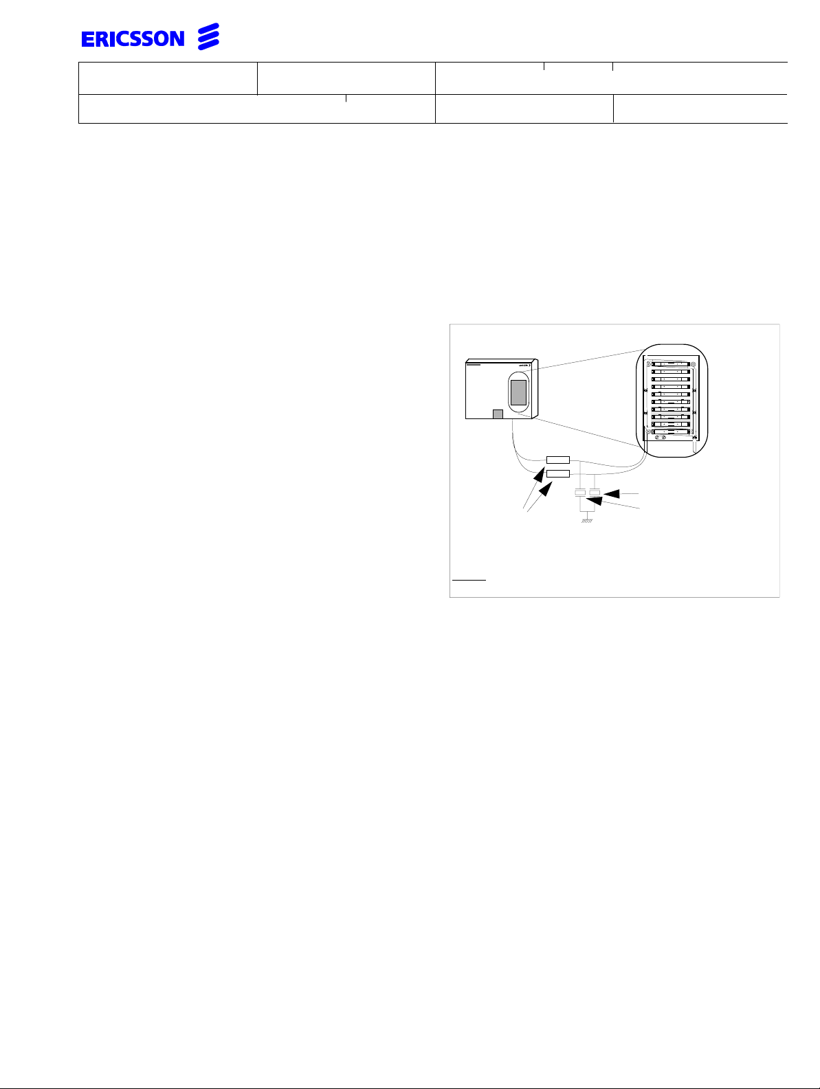
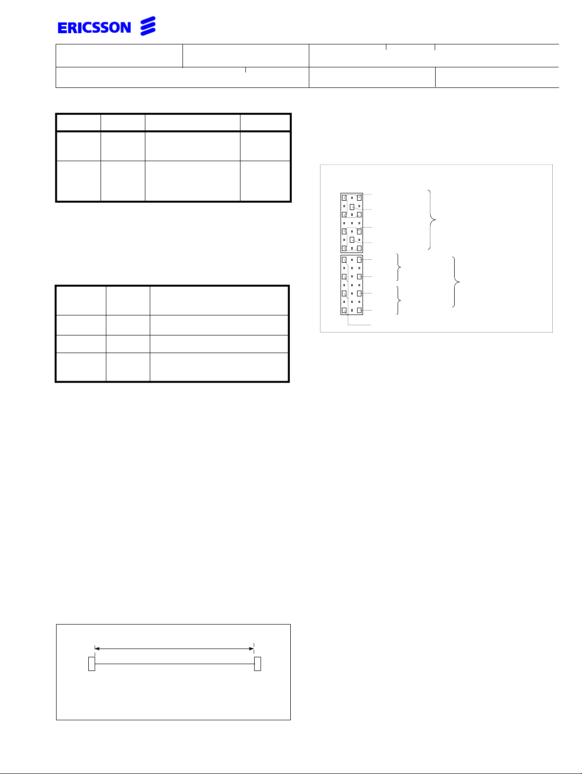
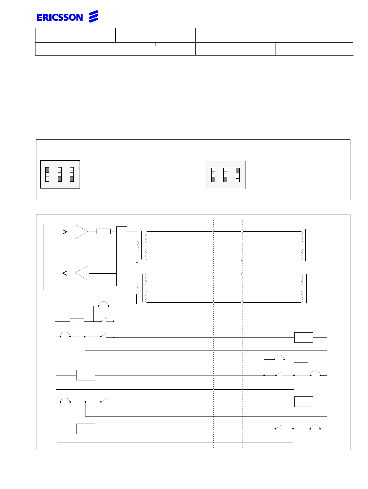
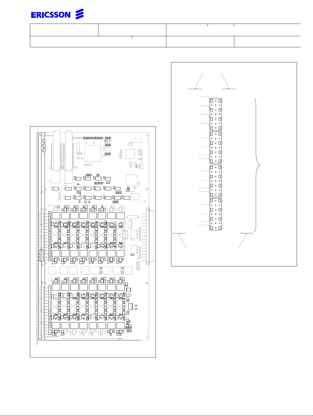
Each branch on the extension line must have:
1 A protective resistor of 10 Ω/1W
(REN 195 42/1) connected in series
between cabinet and MDF
2 An overvoltage arrester (gas discharge
tube) for quenching surges to protective
ground shouldbe installed onthe network
side of the protective resistor.
MDF
Overvoltage arresters
Protective
resistors 10 Ω/1W
(REN 195 42/1)
Protective
ground
(NGC 402 01)
Housed in:
overvoltage protection
cassette (769 027/3)
Note: Make sure the MDF is really connected
to protective ground.
Principal circuit drawing.
Don’t use older board revision states in the new
cabinet.
In principle, a cabinet’s board position can be used for
arbitrary furnishing with boards belonging to PBX
system ASB150 02 butthefirst position isreserved for
the CPU-D_.
Due to the limited load of the cabinet’s power supply
units, the definitive board configuration in a cabinet
must follow the prerequisites in section 6.3.
However, it isadvisable to protect trunk lines withextra
overvoltage protectors especially in geographical
areas highly exposed to lightning.
Any lines connected to the PBX that are subjected to
excess voltage (transients) in conjunction with e.g.
lightning discharges must be equipped with excess
voltage protection.
Special considerations must be taken to analogue
extension lines that are placed outdoors. In order to
prevent the analogue extension boards secondary
protection device from blowing in case of lightning.
1.1 Supplementary documents
• Document collection EN/LZB 103 1233
• INSTALLATION INSTRUCTION
(1531-BML BS 101 01) for the power supply,
equipped with battery charger
1.2 Tools
In addition tocustomaryinstallation tools, the following
are recommended:
• Use theappropriate connectiontool 769027/2 to
connect the cables in the internal MDF.
• Use the appropriate slotting tool LSY138 252 to
connect the cables to the external
MDF SXK 106 4139/1.
• Board extractor for PBAs (handle LTD 117 02
and bottom LTD 117 12)
Page 4

INSTALLATION INSTRUCTION
Subject responsible
DocumentnumberPrepared
1531-BDV BS 101 01 Uen
Doc respons/Approved Checked Reference
Date Rev
1998-05-29
L
2 DECLARATION OF CONFORMITY
5(46)
This page is left blank for the CE-document. Use the link to read the document.
Page 5

Prepared
Doc respons/Approved Checked
Subject responsible
INSTALLATION INSTRUCTION
Documentnumber
1531-BDV BS 101 01 Uen
Date
Rev
Reference
1998-05-29 L
6(46)
This page is left blank for the CE-document. Use the link to read the document.
Page 6
INSTALLATION INSTRUCTION
Subject responsible
DocumentnumberPrepared
1531-BDV BS 101 01 Uen
Doc respons/Approved Checked Reference
Date Rev
1998-05-29
L
7(46)
3 HOW TO OPEN THE
CABINET
Unpack the exchange cabinet.
Using ascrew driverliftthe bluelid. Unscrew thescrew
below and remove the cabinets front cover. Check that
everything hasbeen received accordingto the delivery
note and that nothing has been damaged during the
transport.
businessphone
4 INSTALLATION
The PBX can be delivered as a customer configured
unit or the add-in boards are delivered separately. The
cabinet is always equipped with a power supply,
suitable for the local mains. Please check the label
stating the permitted mains voltage. The cabinet is to
be mounted on an indoor wall. A mains outlet must be
provided near the equipment and shall be easily
accessible. The premises shall comply with the
following prerequisites:
• The air shall be free from dust and smoke
• Environmental conditions according to
ETS 300 019 (1-4) (Temperature shall be
between + 5°C and +40°C and relative humidity
may vary between 15% and 80%)
• The PBX shall not be exposed to direct sunlight
• The cable shall preferablyrun into the PBX from
below the cabinet to ensure sufficient air flow.
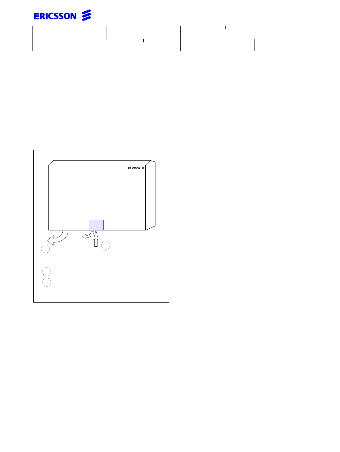
4.1 Mounting of the cabinet
2
1
Lift blue lid to access the screw below.
2
Then turn the screw to loosen the cabinet
1
cover and take off the cabinet cover.
Use the enclosed drilling plan and drill four 8 mm
holes. Mountthe cabinet byusingthe enclosed screws
and plugs. Take into consideration the normal working
height above the floor (about 1.30 m to thelower edge
of the cabinet) and leave enough room for access on
both sides of the cabinet.
Overall dimensions of the cabinet:
• 485 x 600 x 134 (H x W x D in mm).
Page 7
INSTALLATION INSTRUCTION
Subject responsible
DocumentnumberPrepared
1531-BDV BS 101 01 Uen
Doc respons/Approved Checked Reference
Date Rev
1998-05-29
L
4.2 Safety and EMC
8(46)
To fulfil electrical safety requirements IEC 950 and
EN 60950 respectively EN 41003, the exchange must
be connected toprotective earth via a flexible wire with
a cross sectional area of at least 6 mm2.
Local requirements shall be adhered to.
The connection must be carried out by authorised
personnel.
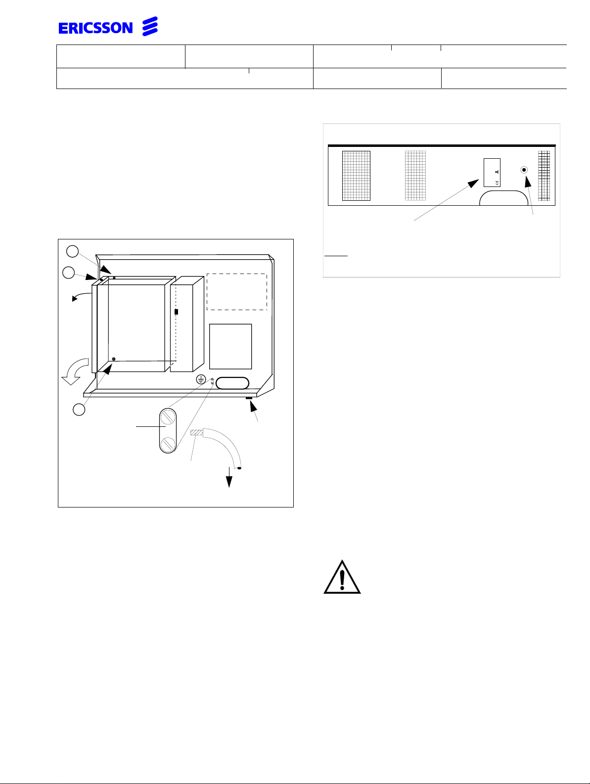
A
B
BATT.
Shelf
cover
SWIVELSHELF
Turn
out
PSU
MDF
A
Connection
for protective
earth
cross sectional area >6 mm
2
Wrist strap
connector
(only for
AUSTRIA)
Front edge
168
Label
SVB BS 101 02/_
Note: The mains current rating stated on the label
is the maximum current of the charger version.
Bottom view of cabinet BDV BS 101 01
All line interfaces in the PBX are protected in
accordance with K.21 (voltage transients up to 1.5kV).
BTU-A, BTU-A2, BTU-B, BTU-C, BTU-D and BTU-E
are working with interface TNV.
All other boards and the V.24 port work with interface
SELV.
4.2.1 EMC
The ferrites, with the ERICSSON ordering number
STF 82 601, should be situatedclose to the slot where
the cablesare led outof the cabinet.Twoturnsthrough
the ferrite core are sufficient to comply with EN 55022
Class B and to avoid disturbances in non-industrial,
residential (home) usage.
snap-on
wrist strap
connector
Protective earth
Before operating,ensure that the chassis isconnected
to a hard wired protective earth.
4.3 Access to the boards
NOTE:
Turn out the transport screws (A)about 1 cm at thetop
and bottom of the swivel shelf. See figure in section
4.2. Hold the bottom of the shelf, lift the shelf slightly
and turn the swivel shelf counter clockwise(ccw). Turn
the screw (B) two turns at the top of the shelf cover
and remove the cover.
Makesure thatasound groundconnection to
the exchange has been established. Otherwise this can be hazardous in case of lightning. Use a grounding wrist strap when
handling PBAs sensitive to electrostatic discharges.
Page 8
INSTALLATION INSTRUCTION
Subject responsible
DocumentnumberPrepared
1531-BDV BS 101 01 Uen
Doc respons/Approved Checked Reference
Date Rev
1998-05-29
L
9(46)
5 POWER SUPPLY UNIT
The power supply units (PSU) for the cabinet are
AC/DCswitching powersupplieswith two inputvoltage
ranges. Please check if the label states the proper
mains voltage as required. For mains supplies with
230V to 250V AC, two versions are available:
• BML BS 101 02/1 (PSU 230V standard)
• BML BS 101 01/1 (PSU 230V equipped with
battery charger).
Formainssupplies with 115V to127V AC twoversions
are available:
• BML BS 101 02/2 (PSU 115V standard)
• BML BS 101 01/2 (PSU 115V equipped with
battery charger).
The PSUs deliver 25 W on the PBA supply voltages
and 80 W on the 48 V supply voltage. After switching
on, the power supply has a start-up delay of 8
seconds.
Warning: The power switch does not disconnect
from mains. The mains cord must be unplugged to
disconnect the mains.
The PSU is equipped with a mains fuse rated
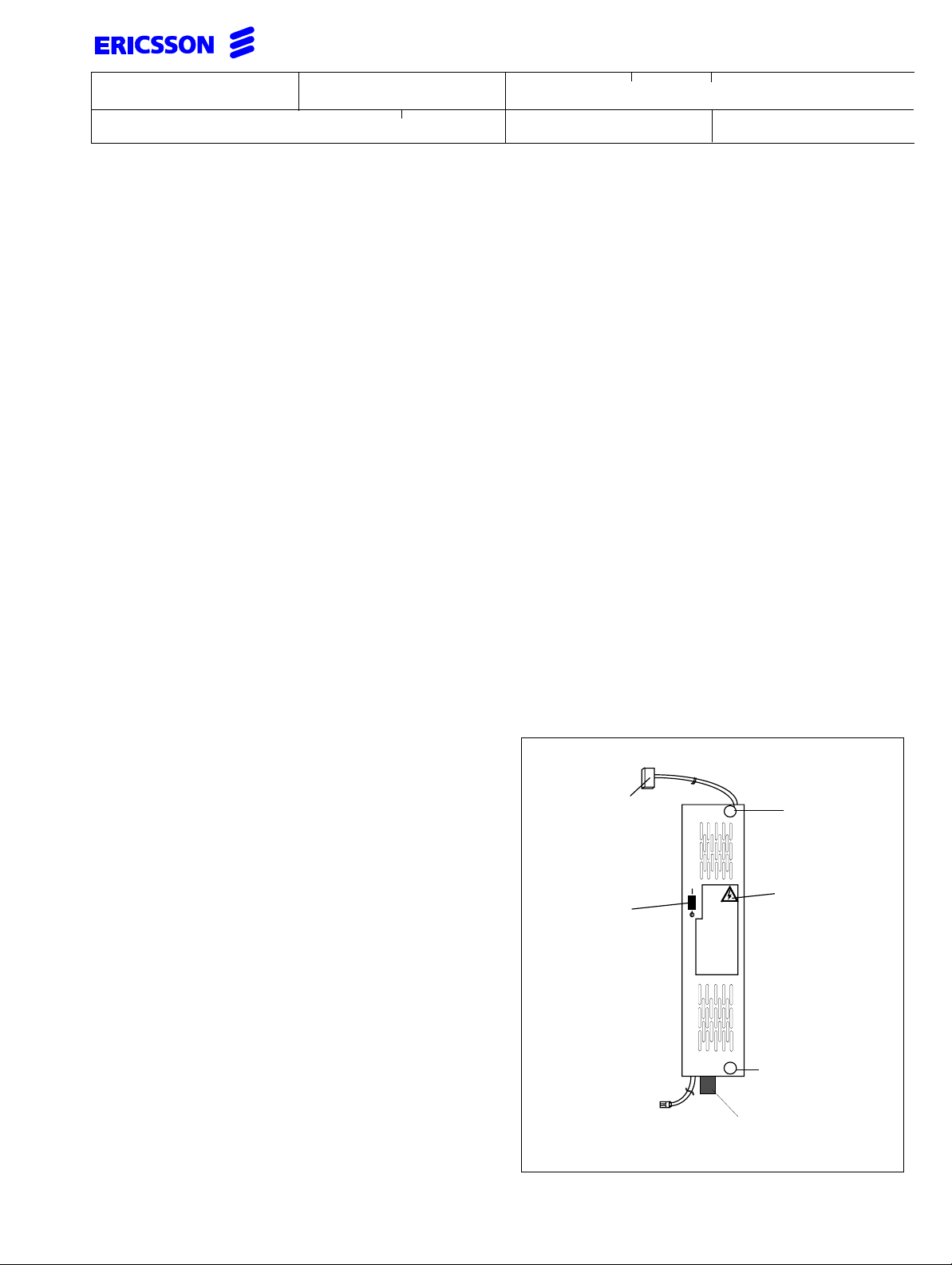
5.1 Replacement of the power supply unit
The cabinet is delivered with a PSU already installed.
The procedure how to dismount the unit is described
below.
a Switch off the PSU (A) and unplug the mains
from the wall outlet. If the unit is a PSU with
battery charger, disconnecttheDC supplyline to
the batteriesand plugoff the alarmconnector on
the unit.
b Disconnect the DC supply cord (D) to the swivel
shelf.
c Unscrew the transport screw(B) completely and
make 3 turns on screw (C) counter clock wise.
d Push the PSU from the bottom and turn out the
PSU clock wise, unhinge and take it out. Then
pull off the mains plug at the bottom of the PSU
and disconnect the ground wire.
e Install the PSU in the reverse manner.
When installing a power supply unit with battery
charger and battery backup please refer to the
INSTALLATION INSTRUCTION
(1531-BML BS 101 01).
250VAC 6,3 A T.
NOTE: This fuse NGH 243 01/6300 can be ordered
from Ericsson but is a non-accessible and non-user
serviceable part. Only authorised personnel is
allowed to change the fuse. Contact the local
supplier in this matter.
Battery backup time
The batteries in the integrated battery pack have a
capacity of 2Ah. The power consumption on the 48 V
should be less than 1.7A. Using fresh batteries a
backup time of 20 minutes is guaranteed and
depending on the system configuration longer backup
times could be achieved.
(D)
Power switch
does not
disconnect
unit from
mains.
Standby only
Ground
(A)
(B)
Label
(C)
Mains power cord plug
IEC 320 C17
Page 9

Prepared
Subject responsible
INSTALLATION INSTRUCTION
Documentnumber
10(46)
1531-BDV BS 101 01 Uen
Doc respons/Approved Checked
Date
Rev
Reference
1998-05-29 L
5.2 Power feeding with an external DC supply
When the PBX is supplied with power by an external battery with 48V nom. (44 - 56V), the installation of a power
supply equipped with a battery charger (BML BS 101 01/_) is required. The DC supply is connected directly to the
PSU.
An externally accessible fuse 250VAC 6,3 A T isprovided on the PSU,but additionally a fuse must be installed in the
supply line with DC current switching capability greater than 160 A.
Note: To prevent arcing never connect the DC source when the PSU has not started-up.
Use the mains to power up or use an external switch to connect the DC source. This is a precaution to minimise the
contact loads on the plug.
For further details see INSTALLATION INSTRUCTION (1531-BML BS 101 01).
Battery operation often requires different preconditions consequently, only an overview can be provided with regard
to battery capacity/charging capacity. The batteries should be supplied locally. The type is described in detail in
INSTALLATION INSTRUCTION (1531-BML BS 101 01).
6 ALLOCATION
In principle, all board positions in cabinet BDV BS 101 01 can be used for arbitrary configurations with PBAs
belonging to PBX-system ASB 150 02.
The boards are equipped with ground brackets on the top and bottom. When installing make sure to fasten the
boards with the supplied screws.
There arerecommendations for configurationsin order to simplifyoperation and maintenance.For further information
see document collection EN/LZB 103 1233.
Sub-equipped boards:
Install sub-equipped boards in the last position after the standard boards to enable easy upgrading without having to
re-number trunks and extensions.
6.1 Power supervision of ELU-A
The board is equipped with an automatic traffic limiter restricting the internal power dissipation on the board to a
maximum of 12W. This depends on both the line length and the number of lines busy.
When the power consumption exceeds the limit, no more lines have access for use and at least two lines have to go
on hook for all lines to work normally again.
When connecting external voice systems a maximum of 8 lines are recommended on each board. The remaining
lines on the board are to be connected to low-traffic extensions.
Page 10
Prepared
Subject responsible
INSTALLATION INSTRUCTION
Documentnumber
11(46)
1531-BDV BS 101 01 Uen
Doc respons/Approved Checked
Date
Rev
Reference
1998-05-29 L
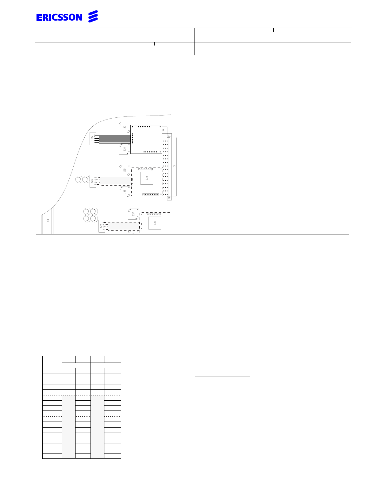
6.2 Connection of CM-Boards
Connect the correct type of call metering board, according to the figure below, on BTU-A board ROF 157 5110/_ or
ROF 157 5127/_ and in the same fashion on the BTU-C board ROF 157 5111/_. The BTU-C cannot be equipped
with a CM50 board as the flat ribbon cable cannot be connected and CM12/16 (ROA 219 5135/1).
Line 0 - 1
CMboard
Line 2 - 3
Note: When installing a CM50-board connect the
cable before mounting the CM50-board. The
BTU-A board must also be connected to
Line 4 - 5
earth.
The following boards are available CM50 ROA 219 5064/1, with flat ribbon cable and CM12/16 ROA 219 5135/1 or
ROA 219 5062/1 without cable.
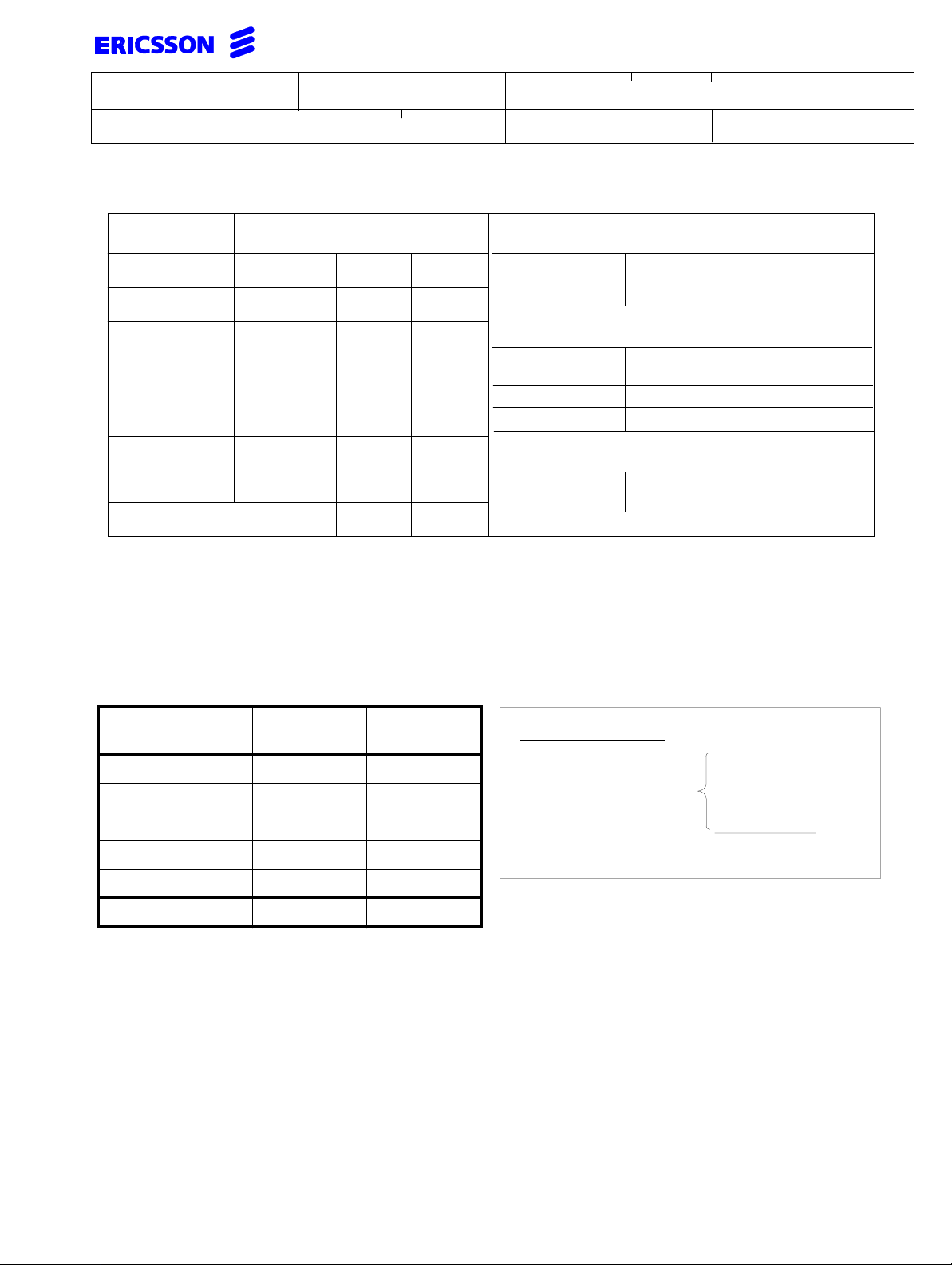
6.3 System Power Consumption
The power demand of the system comprises the sum of the current demands of all extensions, base stations etc.
This total current hastobe delivered by the power supply. Choose the one delivering therated current with a suitable
margin for add on equipment depending on the installation site.
Base Station Power Demand
To minimise the power dissipation on the serial communication wires EPP should be used extensively. Up to 60 BS
can be installed in a cabinet. Short power peaks can be covered by installing a battery cabinet.
The total current for all BS must be less than the power supply(s) capacity. The total 48 VDC load on the power supply has to be calculated as follows:
Cable
length
0m
100m
200m
300m
400m
500m
600m
700m
800m
900m
1,0km
1,1km
1,2km
1,3km
1,4km
1,5km
1,6km
STD EPP
0,5 mm
104
104
110
106
114
110
112
121
115
129
119
121
125
129
133
139
146
152
160
171
183
204
∅
STD EPP
0,6 mm ∅
104
104
108
106
110
108
114
109
118
110
112
114
117
118
121
123
125
127
129
131
135
137
STD EPP
0,5 mm
77
104
83
106
87
110
112
94
115
103
119
121
125
129
133
139
146
152
160
171
183
204
∅
STD EPP
0,6 mm ∅
104
104
108
106
110
108
114
109
118
110
112
114
117
118
121
123
125
127
129
131
135
137
This table states the current demand in mA for a Base Station depending on the cable length and cable diameter.
Calculation example:
Line length to Base Station:
Resistance of loop:
Cable diameter (
φ):
200m
0.18 Ω/m
0,6 mm
Assuming 4 Base Stations are already
connected they consume a current of:
440 mA
Power demand taken from Power Calculations below, for telephones:
984 mA
Total load on power supply: 1424 mA
This total load for the exchange can be
suppliedby thepowersupply asitis less
than 1.7A.
Page 11
Prepared
Doc respons/Approved Checked
Subject responsible
Extension Power Demand
INSTALLATION INSTRUCTION
Documentnumber
1531-BDV BS 101 01 Uen
Date
Rev
Reference
1998-05-29 L
12(46)
TELEPHONES
BASIC
ECONOMY
ECONOMY
plus
STANDARD
EXECUTIVE
DBC 213 with 2 DBY 409 01
DBC 213 with 4 DBY 409 02*)
1
) provides current on trunk lines in active state to public exchange.
CURRENT CONSUMPTION
Typ (mA)Max (mA)
DBC 210
DBC 199
DBC 601
DBC 751
DBC 211
DBC 201
DBC 212
DBC 202
DBC 631
DBC 755
DBC 752
DBC 213
DBC 203
DBC 662
DBC 753
14
25
27
38
14
30
14
30
65
50
50
35
35
70
75
42
35 70
35
35
32
35
50
35
50
70
73
73
70
70
73
70
TELEPHONES
OPERATOR
CONSOLE
DBC 214 with 2 DBY 409 01
DBC 214 with 4 DBY 409 02*)
ANALOGUE
(in active state)
TAU 2610
Desktop Adapter
BTU-B (S-interface
per physical link)
BTU-C
index (/1,/2)1)
Radio base station:
CURRENT CONSUMPTION
Typ (mA)Max (mA)
DBC 214
DBC 663
DBC 754
40
67
75
35
35
40
4
(per trunk)
refer to table above
14
50
120
110
70
70
4
23
50
35
The maximum values for telephones result when all LEDs are lit and if available, loudspeaking is on at max. volume.
*) with connected external power supply.
Power calculation example
LINE
EQUIPMENT
QUANTITY
DBC 210 3 54
DBC 201 5 150
DBC 202 13 390
DBC 203 10 350
CURRENT
(mA)
Calculation example:
selected
line equipment
3 x DBC 210
5 x DBC 201
13 x DBC 202
10 x DBC 203
1 x DBC 663
Total: 32 system telephones
DBC 214 1 40
TOTAL 32 984
The calculation above shows howto calculate the current demand fora given installation. This amount of currenthas
to be supplied by the installed power supply.
Page 12
INSTALLATION INSTRUCTION
Subject responsible
DocumentnumberPrepared
1531-BDV BS 101 01 Uen
Doc respons/Approved Checked Reference
Date Rev
1998-05-29
L
13(46)
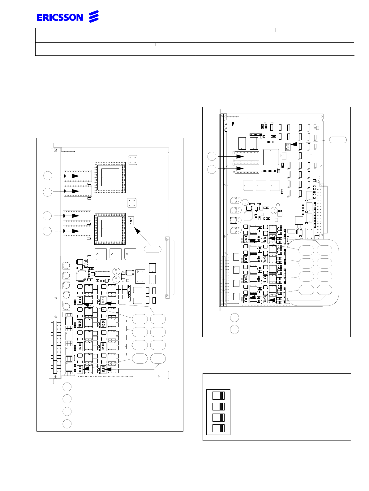
6.4 BTU-A (ROF 157 5110/-) and BTU-A2 (ROF 157 5120/_)
On delivery from the factory both contacts are in the OFF
position, and the line is a normal trunk.
When both contacts on a DIP-switch are set to position
ON, the line is to be regarded as a music source input.
Different contact positions are not allowed.
Note: Only lines4-7canbeused as a music source
input. Not available on BTU-A subequipped ROF
157 5127/_.
.
The DIP-switch is shown
with both contacts in
OFF position
ON
1 2
86
85
Line 4
Line 5
Line 6
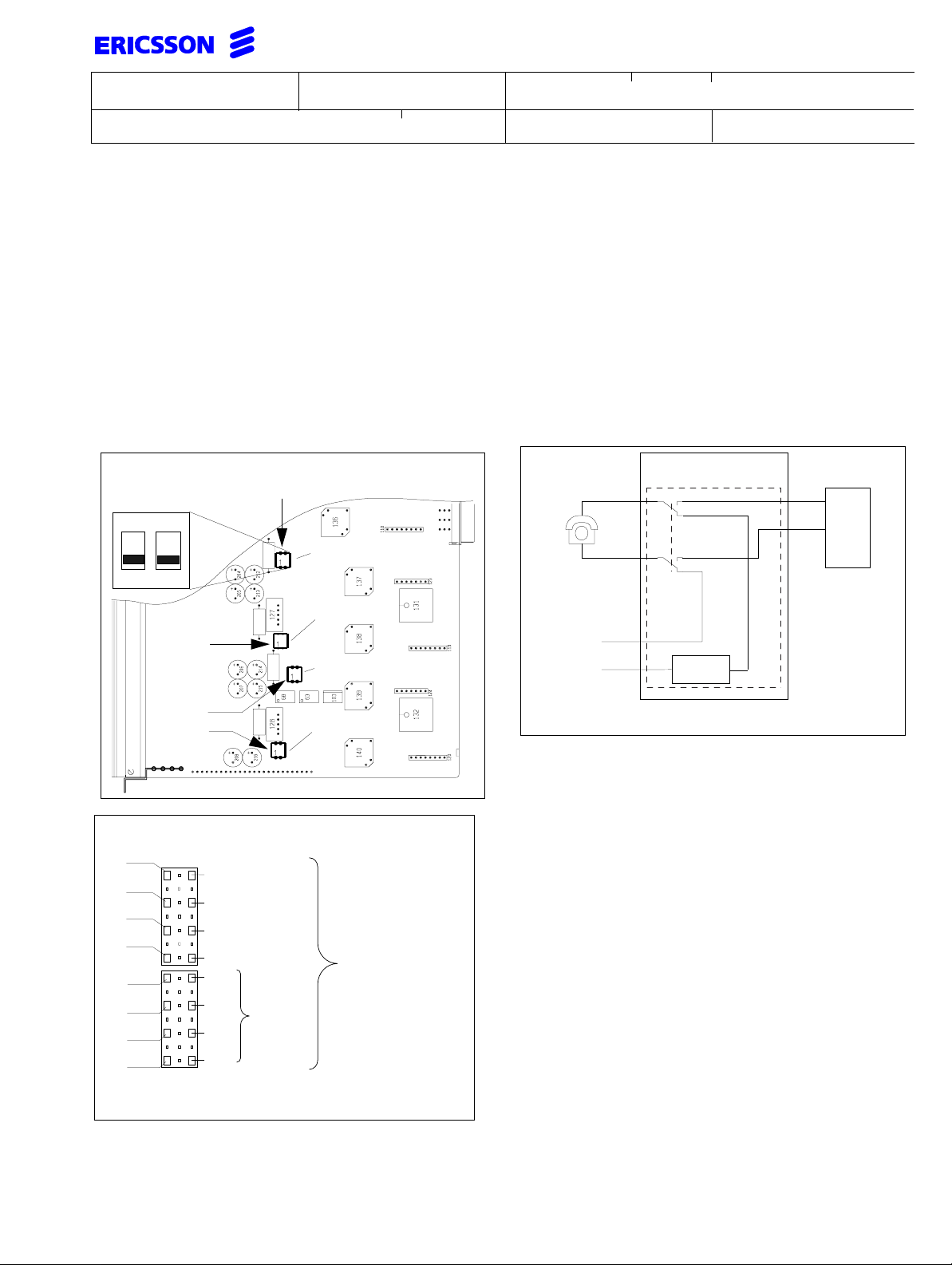
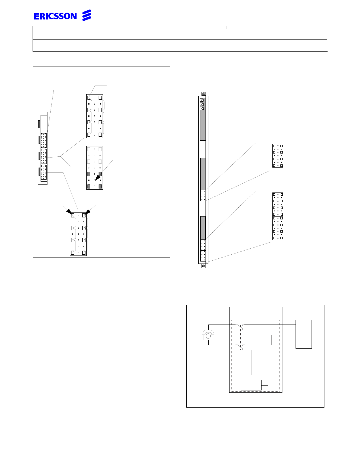
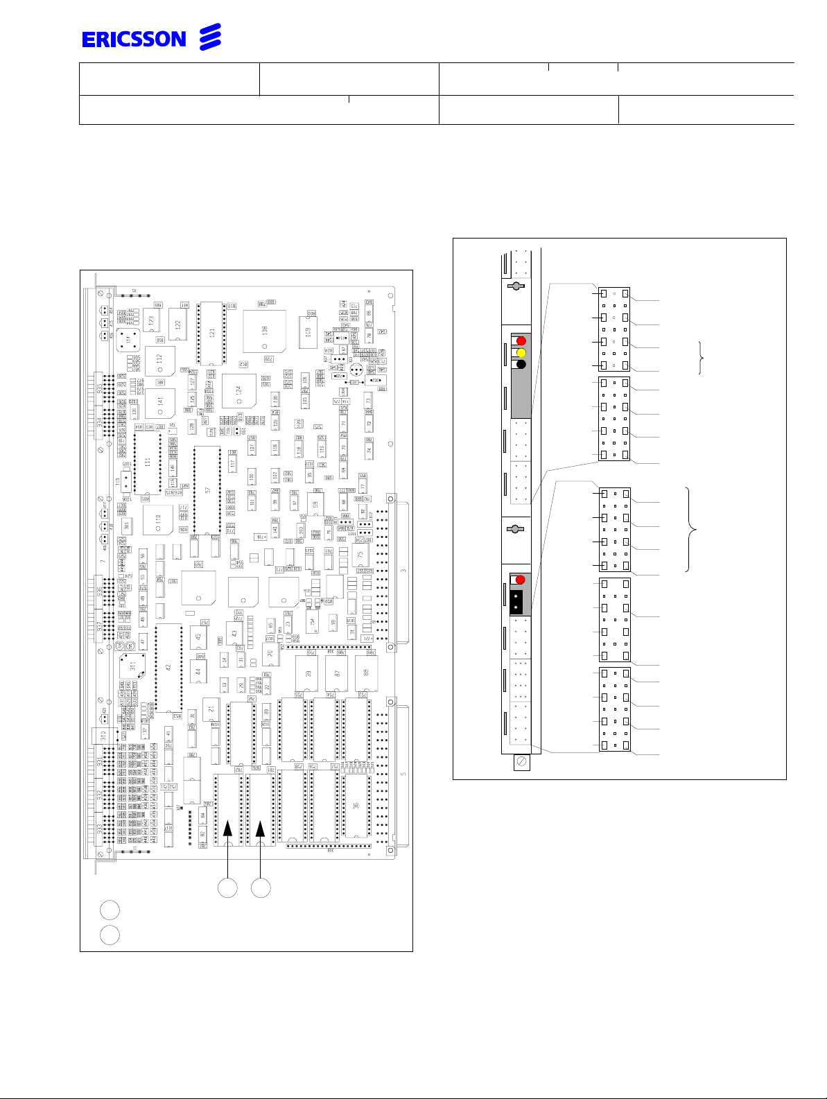
6.5 Power failure circuit (PFC)
In the event of mains failure and if no battery back up
is available for the PBX, there are normally 2 lines on
the BTU-A and BTU-C (see under BTU-C on next
page) board which automatically switch the trunk lines
to analogue telephones connected to this board.
On power failure, these telephones will automatically
be connected to the public exchange.
It is also possible to use the power failure telephones
during normal operation, if an ELU-A board is installed.
BTU-A & BTU-C1
bPFb
ELUA
a
PFa
Power failure set
La
Trunk
Lb
BTC
Indicator
87
88
Line 7
Connection field 6
C
LA0
LB0
LA2
LB2
LA4
LB4
LA6
LB6
*)
A
18
20
22
24
26
28
30
32
LA1
LB1
LA3
LB3
LA5
LB5
LA7
LB7
Line wires for
connection to
Public Exchange
*)
Not available on sub-equipped board see below
Relay shown in power fail position
Page 13
INSTALLATION INSTRUCTION
Subject responsible
DocumentnumberPrepared
1531-BDV BS 101 01 Uen
Doc respons/Approved Checked Reference
Date Rev
1998-05-29
L
14(46)
Connection field 4
Not always mounted
(market-dependent)
18
PFa0
4
PFb0
PFa1
PFb1
20
22
24
18
20
22
24
Connection
to analogue
telephone(s)
PFa2
PFb2
PFa3
PFb3
A
26
28
30
32
A
C
analogue telephone
a0
Connection to
ELU-A board
b0
a1
b1
On the BTU-A2 the
bottom half of this
connector is used
to connect to PTT
signalling ground
Connection to
ELU-A board
C
Connection of
a0
Only mounted if the BTU-A
has 4 PFC circuits (market
b0
dependent).
This connector is used
a1
for PFC circuits on the
BTU-A2
b1
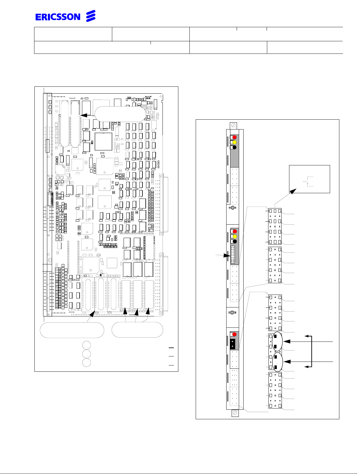
6.6 BTU-C (ROF 157 5111/-)
Connection field 4 and 6
RED
YELLOW
GREEN
The index number
refers to the individual
on the board
power failure (field 4)
PFa0
PFb0
A C
a0
b0
trunk lines (field 6)
La_0
Lb_0
La_2
Lb_2
La_4
Lb_4
La_6
Lb_6
A C
La_1
Lb_1
La_3
Lb_3
La_5
Lb_5
La_7
Lb_7
Earth connection on BTU-A2 (Austria only)
Some markets require an earth connection of the incoming PTT earth (functional earth) to the exchange.
This is provided on the connector installed above the
PFC circuit connectoron pins A22, A24, C22and C24.
Use an extra Krone bar toconnect the PTT earth wires
to the wires going to the board connector.
The BTU-C (ROF 1575 111/1)features eight incoming
trunk lines with DID. The first four individuals can also
be used for outgoing traffic.
BTU-A & BTU-C1
BTC
PFa
Power failure set
bPFb
ELUA
a
La
Trunk
Lb
Indicator
Relay shown in power fail position
Page 14
INSTALLATION INSTRUCTION
Subject responsible
DocumentnumberPrepared
1531-BDV BS 101 01 Uen
Doc respons/Approved Checked Reference
Date Rev
1998-05-29
L
15(46)
6.7 BTU-B (ROF 157 5121/_)
Applies for indices 1 and 3
The BTU-B provides connection for up to 8 physical
links and every physicallink can be configured as a Sor T-interface. On the S-interface every link provides
remote power feeding with 40V/50 mA = 2W and connection for up to 8 terminals.
A
B
C
ON
D
418
6.8 BTU-B2 (ROF 157 5121/_)
Applies for indices 4 and 5
418
A
B
410 411
ON
ON
ON
ON
Insert PROM "RYS 102 521/ 1
A
Insert PROM "RYS 102 521/ 2
B
Insert PROM "RYS 102 521/ 3
C
Insert PROM "RYS 102 521/4
D
ON
ON
ON
ON
410 411
412 413
414 415
416 417
412 413
414 415
416 417
Insert PROM "RYS 102 521/ 3
A
Insert PROM "RYS 102 521/ 4
B
DIP-switches position 410-417
These switches control S- and T-interface termination
and S-interface power feeding on the link 0...7.
On factory delivery all
switches are set to OFF
4
Connects power feeding ground
3
Connects -40V for power feeding
21
Connects 100 Ω receive side termination
ON
Connects 100 Ω send side termination
Page 15
INSTALLATION INSTRUCTION
Subject responsible
DocumentnumberPrepared
1531-BDV BS 101 01 Uen
Doc respons/Approved Checked Reference
Date Rev
1998-05-29
L
16(46)
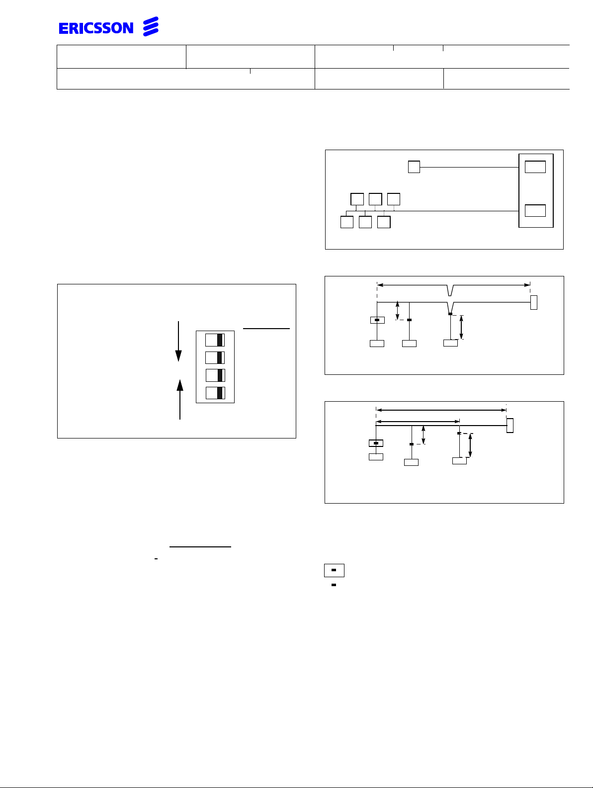
Note: at the end of each line a termination resistor
must be installed (e.g. in the last wall outlet).
The switch 1 selects the termination on the transmitter
interface and switch 2 selects the termination on the
receiver interface. Switches 3 and 4 enable remote
power feeding to ISDN terminals connected to a link.
When connected as S-interface switches 1...4 should
be set to ON.
Settings of the S-interface relevant on
board indices -3,-4,-5
DIP-switch position 418
When selecting which link is to be configured
as a S-/Q-/T-interfaces start with switch:
Line pairs:
Q/T-interface
OFF... Q/T-Interface
ON ...S-Interface
ON
4
3
21
0 + 1
2 + 3
4 + 5
6 + 7
S-interface
On factory delivery all switches are set to OFF
Note: When selecting S- or T-interfaces start by
setting the T-interfaces using switches 4, 3, 2
and 1 in consecutive order then set the Sinterfaces starting with switches 1, 2, 3 and 4.
Settings of the S-interface
Choose with RASC the configuration of the interface:
Extended passive bus default setting
and Short passive bus.
Ranges on the interface
The BTU-B is equipped with the S/T Bus Interface Circuit eXtended (SBCX). This circuit offers the advantage of covering a higher attenuation on cables.
(refer to documentation of the TE) is also equipped
with a SBCX or equivalent.
1 km (standard range)
TE TE
TE TE TE
Ranges on the extended passive bus
TE
and up to 2 km with
TEs equipped with SBCX
TE
up to 500 m (standard range)
and up to 1.5 km with
TEs equipped with SBCX
SBCX
SBCX
BTU-B
Short passive bus
d1
TE
d4
TE TE
d3
BTU-B
d4 - up to 1m
with TR
in outlet
d1 - 150m to 250m (standard range)
d3 - line to terminal up to 10m
Extended passive bus
d1
d2
TE
d4
TE
BTU-B
d3
25 to 50 meters
d4 - up to 1m
with TR
in outlet
TE
d1 - up to 500m (standard range), d2 - between terminals
1,5 km on 30 nF cables with
TEs equipped with SBCX
d3 - line to terminal up to 10m
Abbreviations:
TE Terminal Equipment
TR Termination Resistor (
installed at the end of the
interface line. Use outlets with resistor mounted
Outlet according to IEC 603-7 with termination
Outlet according to IEC 603-7 without termina-
tion
)
The standard S/T-interface specification considers cableswith 6,5 dBattenuation equivalent toabout 1000m
cable length in single terminal configuration.
Using the S/T Bus Interface Circuit eXtended (SBCX)
up to13 dB line attenuationcanbe covered. The figure
below shows the ranges using standard 0.6 mm diameter twisted pair unshielded cables with a capacitive
load of max. 30nF per km and the terminal equipment
Page 16
INSTALLATION INSTRUCTION
Subject responsible
DocumentnumberPrepared
1531-BDV BS 101 01 Uen
Doc respons/Approved Checked Reference
Date Rev
1998-05-29
L
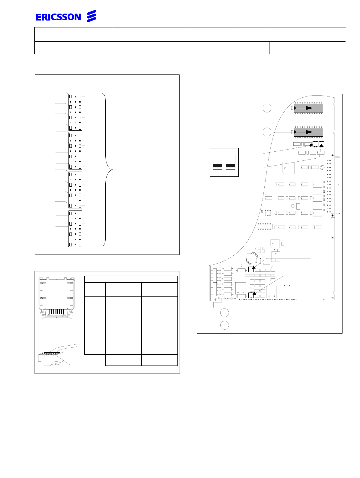
6.9 BTU-D (ROF 157 5112/1) and
Connection field 6
A
T0A
T0B
T1A
T1B
T2A
T2B
T3A
T3B
T4A
T4B
T5A
T5B
T6A
T6B
T7A
T7B
C
02
04
06
08
10
12
14
16
18
20
22
24
26
28
30
32
R0A
R0B
R1A
R1B
R2A
R2B
R3A
R3B
R4A
R4B
R5A
R5B
R6A
R6B
R7A
R7B
The DIP-switch is
shown with
both contacts in
OFF position
S/T-Interface for
connecting trunks
and S-terminals
REG (ROF 157 5112/2)
A
B
ON
1 2
197
200
17(46)
Wall outlet connection
4
5
6
3
8
1
7
2
Wiring side of 8-pole
wall outlet e.g.
KRONE RJ-K LN
Pin desig-
nation
optional
1
EIA/TIA 568 Wiring Schemes
NT function: TE function:
(polarity of remote
Transmit (-)
5
4
Transmit (-)
Receive (+)
3
6
Receive (+)
1
Power sink 3 (+)
2
Power sink 3 (-)
7
Power source 2(-)
8
Power source 2(+)
S-interface in
socket
(polarity of remote
power feeding)power feeding)
Receive (-)
Receive (-)
Transmit (+)
Transmit (+)
Power source 3(+)
Power source 3(-)
Power sink 2(-)
Power sink 2(+)
T-interface on
plug
199
198
Insert PROM "RYS 102 5xx/1
A
Insert PROM "RYS 102 5xx/2
B
6.9.1 DIP-switches in position 197 and 200
Depending on the firmware used, this board enables
either ISDN or CAS function. The PROM set is available for CAS (LZY203 2212/1) or ISDN PRA
(LZY203 2213/1). DIP-switch pos. 197 on BTU-D selects the register function of the board. The switch 200
is reserved for future use.
Page 17
INSTALLATION INSTRUCTION
Subject responsible
DocumentnumberPrepared
1531-BDV BS 101 01 Uen
Doc respons/Approved Checked Reference
Date Rev
1998-05-29
L
18(46)
197/1 197/2 FUNCTION
OFF OFF
ON
ON OFF
ON
digital trunk MFC
digital trunk MFE
Register MFC
Register MFE
only
BTU-D
BTU-D
or
REG.
6.9.2 DIP-switches in positions 198 and 199
Selection of ground strapping for the coax 75 Ω or selection of the 120 Ω twisted pair interface.
198/1
199/1
OFF OFF
198/2
199/2
FUNCTION
120 Ω connection
1)
OFF ON screen connected toground
ON OFF screenconnected toground
via 1nF capacitor
1) Factory setting
On factory delivery the switches are set to OFF-position = no ground thus enabling 120 Ω interface with a
twisted pair cable. These DIP-switches connect the
75 Ω interface coaxscreento ground, either directly to
0Vorviaa1nFcapacitor.DIP-switch 198 switches the
receiver and199the transmitter side. The screenshall
normally be grounded on the transmitter side. Normally, the screen on the reception side isnot connected to
ground. Refer to local market requirements
Ranges on the interface of the BTU-D
This interface coversthe short distance to the next NT
or Line Terminating Unit as the end point of a public or
private network. The range is only defined in terms of
the covered attenuation by the interface that is 6 dB. If
required choosecables with low attenuationto achieve
a maximum distance.
For ranges exceeding 6 dB attenuation additional digital data transmission equipment is required. Line Terminating Unit (LTU) ASB 501 04 is available for such
purposes.
Connection field 6
A
C
18
19
20
22
23
24
26
28
30
32
RING_OUT
TIP_OUT
RING_IN
TIP_IN
LA1
Outgoing
wires
LB1
LA2
Incoming
wires
LB2
Connection for 75 Ω
coaxial cable
Connection for
120 Ω twisted pairs
0 V
There are specificrequirements for thedigital interface
wiring to meet the demands of EMC.
If a twisted pair connection shouldbeinstalled and the
requirements of EN 55022, class Bhave to be fulfilled,
a ferrite is available with the ERICSSON ordering
number STF 82 601. Taking the cable and making
three turns around the ferrite core meets the demand
of sufficient noise reduction. The ferrite should be
situated close to the slot where the cables are led out
of the cabinet. In most cases this cable is supplied by
the PTT and should not be fed via the MDF.
Some markets (e.g. Austrian PTT) require the use ofa
double-shielded interface cable. The outer shield
should be connected to frame earth and the inner
shield shouldbe connected to0V on the board.A 20 m
long standard cable is available with the ERICSSON
ordering number TSR 901 0481/20000.
Coax 75 Ω and twisted pair 120 Ω interface
d1
Line terminating unit BTU-D
d1 - The line length depends on cable type used. The board
allows 6 dB cable attenuation at 1.024 MHz. Check cable
attenuation at 1,024 MHz per 100m.
Page 18
Prepared
Doc respons/Approved Checked
Subject responsible
6.10 BTU-E (ROF 157 5113/_)
INSTALLATION INSTRUCTION
Documentnumber
1531-BDV BS 101 01 Uen
Date
Rev
Reference
1998-05-29 L
19(46)
SPEECH CONNECTION SETTINGS
2-wire connection
106...406
on
1 2 3 4
S1 S2
S3 S4
108/308
on
1 2
S5
INDIVIDUAL 0
uses switches 106 and 108/1
INDIVIDUAL 2
uses switches 306 and 308/1
SPEECH CONNECTION SETTINGS
4-wire connection
106...406
on
1 2 3 4
S1 S2
S3 S4
INDIVIDUAL 1
uses switches 206 and 108/2
INDIVIDUAL 3
uses switches 406 and 308/2
Switches select between 2- or 4-wire speech
connection. Two individualsshare switches 108
and 308
On boardswith Rev. R2Athese switchesare replaced byrelays. These relays are setautomatically by programming the filter coefficients.
Connection field 4 and 6 at front of BTU-E_
Speech (field 4)
AC
18
LA_0
LB_0
LA_1
LB_1
LA_2
LB_2
LA_3
LB_3
M2_0
M20_0
M2_1
M20_1
M2_2
1
M20_2
M2_3
M20_3
M1_0
M0_0
M1_1
M0_1
M1_2
1
M0_2
M1_3
M0_3
20
22
24
26
28
30
32
Signalling (field 6)
AC
LC_0
LD_0
LC_1
LD_1
LC_2
LD_2
LC_3
LD_3
E2_0
E20_0
E2_1
E20_1
E2_2
E20_2
E2_3
E20_3
E1_0
E0_0
E1_1
E0_1
E1_2
E0_2
E1_3
E0_3
LA & LB - 2-wire send/receive or 4-wire send.
LC & LD - 4-wire receive.
108/308
on
1 2
RED
YELLOW
GREEN
YELLOW
GREEN
S5
M-WIRE CONNECTION SETTINGS
APPLICATION
PAGING
SPEECH M-WIRES
2-wire
S6..off
S7..off
S8..off
AMERICAN
E&M
SIGNALLING
DOUBLE
M-WIRE
SIGNALLING
CAILHO E&M
SIGNALLING
4-wire
4-wire
4-wire
S6, S7 and S8
see local
requirements
S6..on
S7..on
S8..off
S6..off
S7..off
S8..off
CEPT L1/SSAC 15
Only on /2 boards
4-wire
S6..off
S7..off
S8..off
S6 connects -48V to M1 terminal via 6.2 Kohm
S7 connects 0V to M0 wire locally.
S8 connects 0V to M20-wire.
108
106
206
306
406
308
0
1
2
INDIVIDUALS
3
109
209
10
2
on
1 2 3
S6 S7 S8
309
INDIVIDUALS
3
409
1
M20_ and M0_ can be switched by S7 and S8 to 0V on
the BTU-E_ locally.
M-WIRE SETTINGS
Page 19
Prepared
Subject responsible
INSTALLATION INSTRUCTION
Documentnumber
20(46)
1531-BDV BS 101 01 Uen
Doc respons/Approved Checked
Date
Rev
Reference
1998-05-29 L
6.10.1 Paging connection
The figure shows howto connect the paging equipment Ericall Contactor with 2 wire speech. The PBX sends paging
information to paging system (pin 6A18) using M1 contact, and information about ’paging in progress’ or ’paging
equipment not present’ is received on the E1-wire (pin 6C18) from the paging equipment.
Switch settings
on
This switch setting is used for
signalling on E1 and M1.
1 2 3
S6 S7 S8
Applies for switches 109, 209, 309 and 409.
Z
DSLAC
0V
-48V
0V
S7
S5
M1
Detector
autom. 2/4wire
0V
PBX
4A18
4A20
6A18
6A20
6C18
6C20
LA
LB
M1 E1
M0 E0
E1 M1
E0 M0
Paging equipment
Detector
-48V
0V
0V
Figure showing Paging equipment and 2-wire speech with ’loop connection’ of the E&M-wires.
Page 20
Prepared
Subject responsible
INSTALLATION INSTRUCTION
Documentnumber
21(46)
1531-BDV BS 101 01 Uen
Doc respons/Approved Checked
Date
Rev
Reference
1998-05-29 L
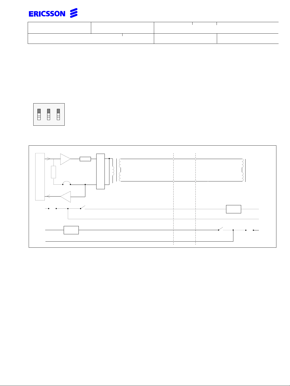
6.10.2 Four wire speech connection
The four wire speech and signalling connection has the benefit of not needing additional signalling wires. There are
two different types of signalling supported:
Cailho E&M-signalling (balanced battery). The two way signalling utilises common mode DC pulses via the centre
tap of the transformer. On one side a detector is connected between the -48 VDC and the centre tap of the
transformer.The other end uses opto relay M4 to switch the line to 0V (Ground). The detector reads the current flow
to ground every time M4 closes.
CEPT L1/SSAC 15 with 2280 Hz tones. In this case no DC signalling is used but instead signalling is performed by
switching on and off a 2280 Hz tone, which is detected by a tone receiver on the other side. This is only available on
index 2 boards.
Switch settings
on
This switch setting inhibits signalling on E1 and M1. Only AC or DC
signalling on the four wire speech connection is used.
1 2 3
S6 S7 S8
Applies for switches 109, 209, 309 and 409.
2280 Hz
DSLAC
2280 Hz
detector
R
0V
autom. 2/4wire
0V
M4
1uF
Detector
560
PBX
LA
4A18
0V
Ω
-48V
4A20
4C18
4C20
LB
LC
LD
PBX or channel equipment
Detector
-48V
0V
Figure showing Cailho E&M signalling and CEPT L1 or SSAC 15 with tone signalling
Page 21
Prepared
Subject responsible
INSTALLATION INSTRUCTION
Documentnumber
22(46)
1531-BDV BS 101 01 Uen
Doc respons/Approved Checked
Date
Rev
Reference
1998-05-29 L
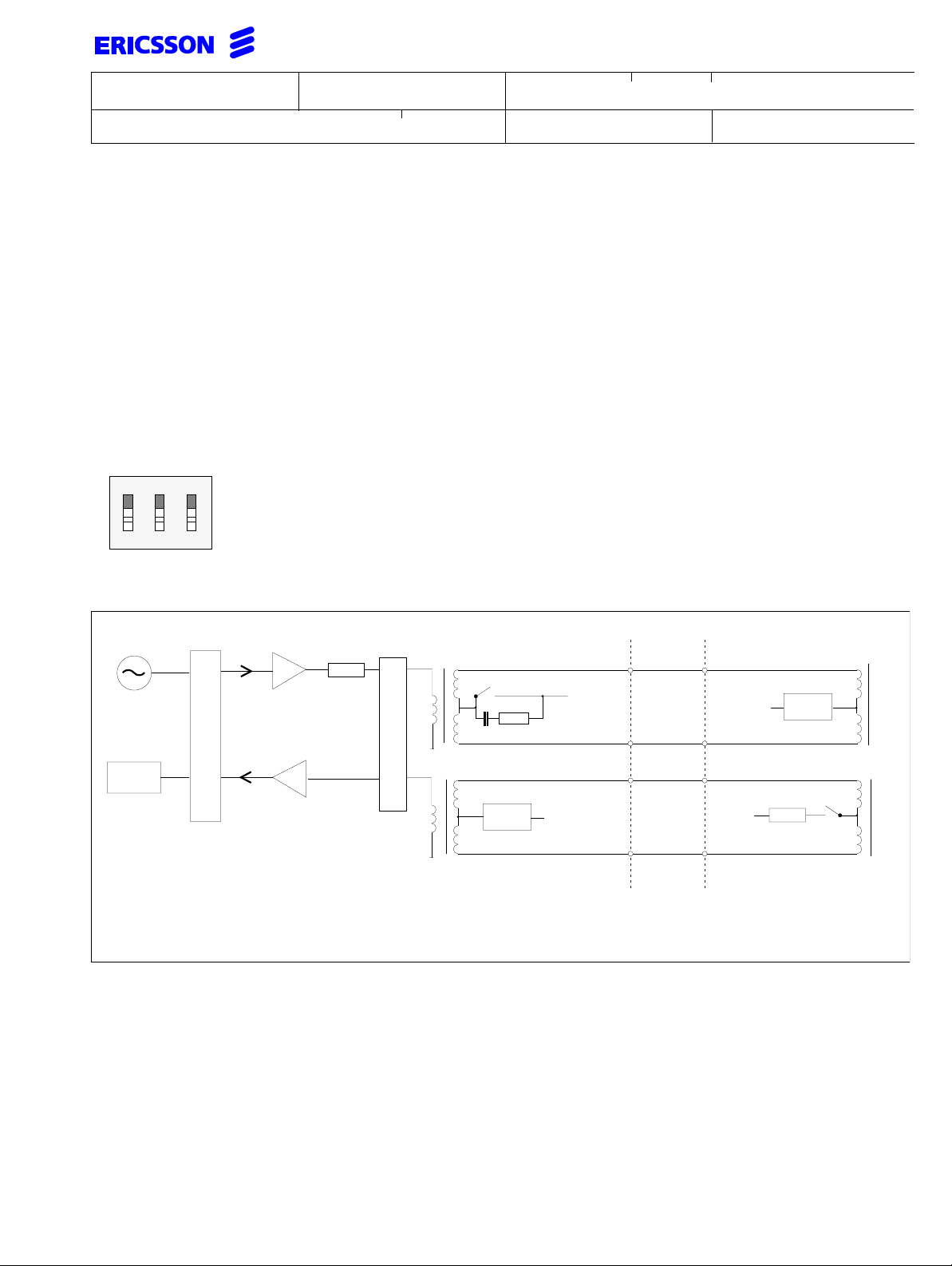
6.10.3 E&M-signalling
Signalling on E & M wires is done either using one or two E&M pairs depending on what is required. Using just E1
and M1 is a very common practice. One case to mention is the American E&M signalling where the M1 wire toggles
between -48VDC and 0V.
Double E&M signalling requires the E1/M1 wires for the signalling of information and the E2/M2 wires indicate
blocking of the connection. The E1/M1-wires are used for signalling and E2/M2-wires are used for blocking. The
figure shows 0V connection to the M-wires in both ends.
Switch settings
Standard E & M signalling
on
This switch setting is used
forsignallingon E1and M1.
1 2 3
S6 S7 S8
Double E & M signalling
on
This is the switch setting when
E1, E2, M1 andM2are used for
signalling.
1 2 3
S6 S7 S8
Applies for switches 109, 209, 309 and 409.
R
DSLAC
0V
autom. 2/4wire
S8**
0V
-48V
0V
-48V
S7
M3**
M1
Detector
**application specific
toggles between 0 and -48VDC
(e.g. American signalling)
PBX
4A18
4A20
4C18
4C20
6A18
6A20
6C18
LA
LB
LC
LD
M1 E1
M0
E1 M1
E0
PBX or channel equipment
Detector
-48V
0V
-48V
0V
E0 M0
0V
0V
-48V
0V
S6
M2
Detector
6C20
6A02
6A04
6C02
6C04
M2 E2
M20
E2 M2
E20
Figure showing four wire speech and standard (double) E&M signalling.
E20
M20
Detector
-48V
0V
0V
Page 22
INSTALLATION INSTRUCTION
Subject responsible
DocumentnumberPrepared
1531-BDV BS 101 01 Uen
Doc respons/Approved Checked Reference
Date Rev
1998-05-29
L
23(46)
6.11 CPU-D_ (ROF 157 5118/_) and
AUX_(ROF1575 119/_)
Before installing the board mount the system software
PROMs in the appropriate positions.
Connections on the CPU-D_
For connection of TEMPERATURE SENSOR KIT, see
INSTALLATION INSTRUCTION (1531-RPM 603 339).
CA
18
Factory test
20
-48 VDC
22
24
26
28
30
32
10
12
14
16
18
20
22
24
26
28
30
32
ALARM
ALARM
External
sensor 3
0 V
Not used
Not used
RTS
DTR
DCD
CTS
RTS
DTR
DCD
CTS
RTS
DTR
DCD
CTS
Polarity
independent
input
only this V.24
port is active
on the AUX3
board
red
yellow
green
red
Cold
start
strap
BS2 9727
CPU-D
R1A
ROF1575118
Audio
Audio
ALARM
(out)
0 V
External
sensor 1
0 V
External
sensor 2
0 V
TXD
0 V
RXD
DSR
TXD
0 V
RXD
DSR
TXD
0 V
RXD
DSR
A B
A
Insert PROM "RYS 102 1x9/ xx
Insert PROM "RYS 102 1x8/ xx
B
r additional CIL storage capacity up to two additional
battery backup RAMs can be added.
The ALARM input is optically isolated and the voltage
has to be between 20 - 60 VDC.
The ALARM output is equipped with an open collector
transistor with a capacity of 20 mA at 12 VDC
(Maximum 14 VDC).
Use the following prefabricated cables to connect the
peripheral data equipment to CPU-D_ and AUX_:
• PC is TSR 902 0448/1
• printer is TSR 902 0476/1
• modem is TSR 902 0466/1
Page 23
INSTALLATION INSTRUCTION
Subject responsible
DocumentnumberPrepared
1531-BDV BS 101 01 Uen
Doc respons/Approved Checked Reference
Date Rev
1998-05-29
L
24(46)
6.12 CPU-D4 (ROF 157 5124/_)
FW PROMS
RYS 102 533/1
RYS 102 533/2
Connections on the CPU-D4
Similar tothe previous versionsthis board providesthe
V.24 interfacesbut additionallythe RS-485interface for
longer ranges. With the software key (FECU)
KDU BS 130 06/_ new functionalities can be accessed.
red
yellow
green
alarm relay
B18
B22
B20
CA
B
ROF1575130
BS2 9727
CPU
R1A
Audio
Audio
red
yellow
green
RTC
FECU
connector
ALARM
(out)
0 V
External
Temp1
0 V
External
Temp2
0 V
18
Factory test
20
-48 VDC
22
ALARM (in)
24
0 V
26
External
Temp3
28
0 V
30
Not used
32
Not used
Battery RAM
Battery RAM
st
1
Battery RAM
KDY BS 101 02/1
Insert PROM "RYS 102 xx1/ x"
A
Insert PROM "RYS 102 xx2/ x"
B
Insert PROM "RYS 102 xx3/ x"
C
Battery RAM
rd
nd
3
2
SW PROMS
C B A
To put the board in operation mount the system software PROMsin the appropriate positions.The number
of battery RAMs mounted on the CPU-D4 board is
functionality dependent.
red
Coldstart
strap
TXD
0 V
RXD
DSR
TXD
0 V
RXD
DSR
TXD
0 V
RXD
DSR
RTS
10
DTR
12
DCD
14
CTS
16
+
RTS
18
-
DTR
20
+
DCD
22
-
CTS
24
RTS
26
DTR
28
DCD
30
CTS
32
Transmit
RS 485
loop
Receive
RS 485
To connect the RS-485 data interface use plug
RNV 321 01 02 be sure to loop RTS with CTS other-
Page 24
INSTALLATION INSTRUCTION
Subject responsible
DocumentnumberPrepared
1531-BDV BS 101 01 Uen
Doc respons/Approved Checked Reference
Date Rev
1998-05-29
L
wise data is lost if printer is OFF. The range of the interface is up to 1200m.
Several converters may be used but with the following
successful tests were accomplished:
IC-485SI from ARP DATACON and
232<->485/422 Converter Plus IC-109AE from Black
Box Corp.
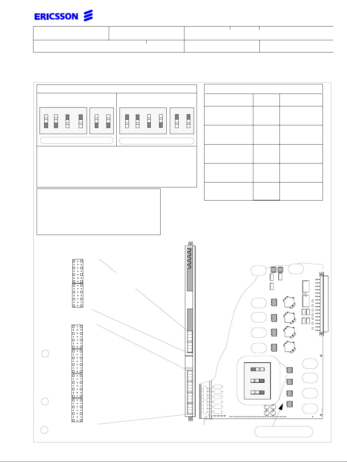
6.12.1 Feature Enabling Control Unit (FECU)
Connecting this plug activates the appropriate applications and features asordered depending on the FECU
index number. If no plug is connected only a limited
Version 3.0 system functionality is available. The indices 2 to 10 always include the Basic Version 3 functionality (index 1).
25(46)
For detailed information of the featuresenabled by the
different FECUs refer to 15534-ASB 150 02 Uen
FACILITY DESCRIPTION GENERAL.
FECU number Functionality Version 3.1
KDU BS 130 06/1 Basic Version 3.0 functionality
KDU BS 130 06/2 + std. digital networking for max.
32 interfaces
KDU BS 130 06/3 + std. digital networking
KDU BS 130 06/4 + full. digital networking for max.
32 interfaces
KDU BS 130 06/5 + full. digital networking
KDU BS 130 06/6 + CTI
KDU BS 130 06/7 + CTI and std. digital networking
for max. 32 interfaces
KDU BS 130 06/8 + CTI and std. digital networking
KDU BS 130 06/9 + CTI + full. digital networking for
max. 32 interfaces
KDU BS 130 06/10 + CTI + full. digital networking for
unlimited number of interfaces
Page 25
INSTALLATION INSTRUCTION
Subject responsible
DocumentnumberPrepared
1531-BDV BS 101 01 Uen
Doc respons/Approved Checked Reference
Date Rev
1998-05-29
L
6.13 ELU-A and ELU-D
Connection field6 at frontof ELU-D(3)and ELU-A
The relevant boards are:
• ELU-D (ROF 1575 116/_)
26(46)
• ELU-A (ROF 1575 114/1)
• ELU-A2 (ROF 1575 114/2)
• ELU-D3 (ROF 157 5130/_)
This switch is mount-
RYS 102 532/2
RYS 102 532/1
ON
3 4
ed for future use
1 2
(LA16)
(LB16)
(LA18)
(LB18)
(LA20)
(LB20)
(LA22)
(LB22)
(LA24)
(LB24)
(LA26)
(LB26)
(LA28)
(LB28)
(LA30)
(LB30)
LA0
LB0
LA2
LB2
LA4
LB4
LA6
LB6
LA8
LB8
LA10
LB10
LA12
LB12
LA14
LB14
02
04
06
08
10
12
14
16
18
20
22
24
26
28
30
32
C
A
LA1
LB1
LA3
LB3
LA3
LB5
LA7
LB7
LA9
LB9
LA11
LB11
LA13
LB13
LA15
LB15
(LA17)
(LB17)
(LA19)
(LB19)
(LA21)
(LB21)
(LA23)
(LB23)
(LA25)
(LB25)
(LA27)
(LB27)
(LA29)
(LB29)
(LA31)
(LB31)
Extension Line
connector to
terminal
equipment
View of the ELU-D3 board
The connections in field 4 are in brackets (only on
ELU-D3 for individuals 16 to 31)
On the first ELU-D_ board in the system the first three
extension positions should be used to connect the
OPERATOR telephones.
On sub-equipped ELU-A and ELU-D_ boards the connection for extensions 8...15 (32) are not mounted.
Page 26
INSTALLATION INSTRUCTION
Subject responsible
Doc respons/Approved Checked Reference
DocumentnumberPrepared
1531-BDV BS 101 01 Uen
Date Rev
1998-05-29
L
27(46)
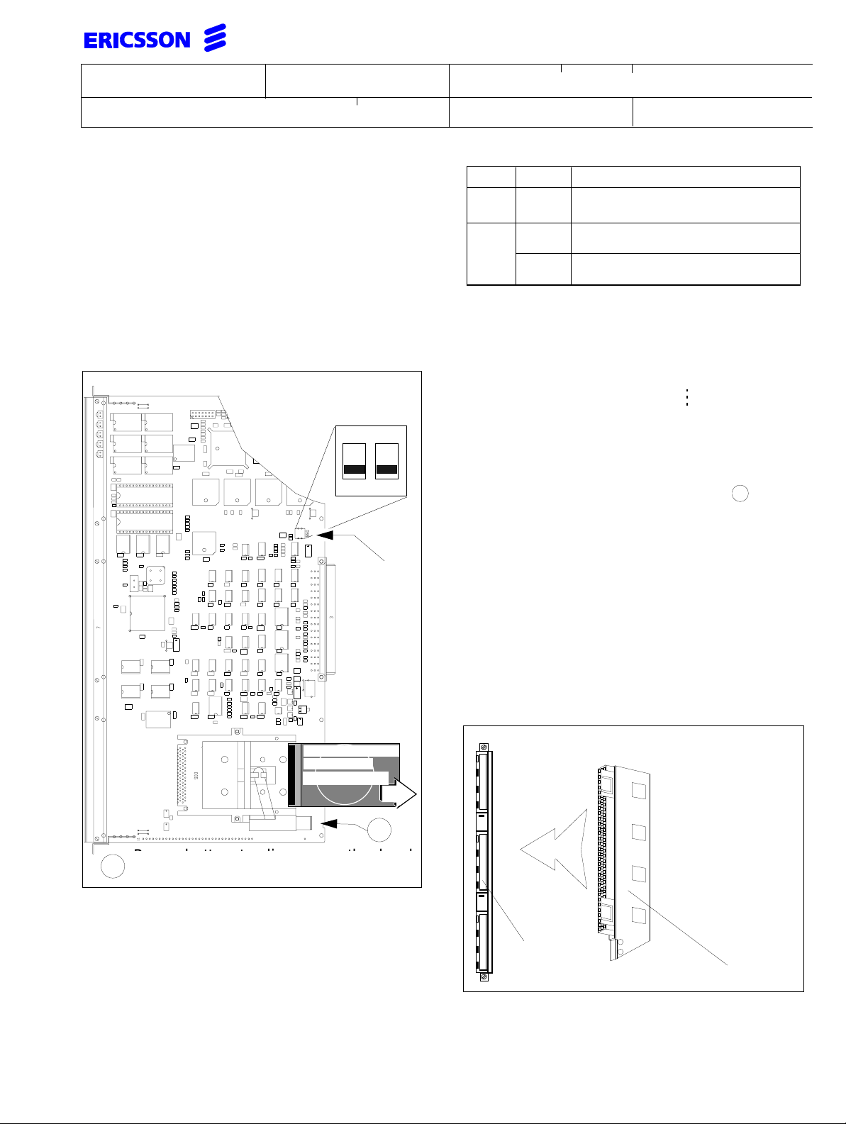
6.14 VMU-HD (ROF 157 5126/1)
To install unpack the VMU-HDboard with the mounted
hard disk.The Flash disksare availablewith a capacity
of 60 MB. Removethe transport protection forthehard
disk and keep it in case of re-shipment e.g. factory repair. Install and configure the VMU-HD in the cabinet
according to the stipulations in 1537-ASB15002Uen
START OF OPERATION.
Note: The VMU-HD will not start up without internal
directories created on the hard disk.
The DIP-switch is shown with
both contacts in OFF position
(factory setting)
ON
1 2
990
990/2990/1 FUNCTION
OFF
ON
Structure of directories on hard disk or Flash card
\Info0 \message2 \anno0
\Info1 \message3 \anno1
Removal of hard disk or Flash card
To remove the hard disk take out the board from the
system. Disengagethehard disk with lever and pull
out the hard disk.
ON or
OFF
OFF
ON
\message4 \anno2
\message5 \anno3
16 channels, no register function
8 channels with MFC detection
and DTMF / Tone receiver
8 channels with MFE detection
and DTMF / Tone receiver
\annoF
A
6.15 VMU-D (ROF 157 5117/1)
PCMCIA Hard/
Flash disk
type III and II
A
Press button to disengage the hard disk and
Press button to disengage the hard
A
take it out.
disk and take it out.
DIP switch on VMU-HD
DIP switch 990 selects whether register function is enabled or not.
Limitations:
Only one VMU-HD can be mounted per cabinet and
just one type either VMU-HD or VMU-D can be installed in a system.
The VMU-D has no switches, but is equipped with a
back up battery, RNV 991 942/001 to prevent loss of
data in case of power failure. Install the battery to connection field4. beforethe exchange isstarted. Forsafe
operation, replace this battery periodically every five
years in accordance with document MAINTENANCE
INSTRUCTION (1541-ASB 150 02 Uen).
Installation of battery back-up on VMU-D
Connection
field 4
Battery RNV 991 942/001
Page 27
INSTALLATION INSTRUCTION
Subject responsible
DocumentnumberPrepared
1531-BDV BS 101 01 Uen
Doc respons/Approved Checked Reference
Date Rev
1998-05-29
L
28(46)
7 INTEGRATED CORDLESS
The Integrated Cordless (IC) is a digital cordless telephone solution complying to the DECT standard providing wireless connection for up to 108portables with
the A-protocol and 210 portables in GAP-protocol applications. Several components comprise a complete
system.
After the system has been physically installed use
RASC and the Cordless System Manager (CSM) for
initialization, maintenance, updating, fault finding and
when possible to recover the PBX from errors. The
CSM is orderable under LZYNB 201 01 R6A or higher
forthe A-protocol and LZYNB201 05 R1B orhigher for
GAP applications.
7.1 Board Descriptions
7.1.1 IC-Control Unit2 (IC-CU2)
The IC-CU2 is the control board supporting the DECT
GAP-protocol. The IC-CU2 includes 8 voice channel
units and is equipped with 4 BSs interfaces.
The wiring distance with remote power feeding to the
BSs using only the serial communication wires SC0
and SC1 is limited to 400m. For line lengths up to
900m additional Express Power feeding Pairs (EPP)
need to be wired. The maximum wire length between
BS (fed locally) and IC-CU2 is only data limited and
may reach up to 900 meters.
The board offers the following connections:
• the Cordless System Manager (on a PC)
• a printer to log errors
• 4 Base Stations
• the Feature Enabling Control Unit (FECU).
7.1.2 Feature Enabling Control Unit (FECU)
plug is available for various numbers of cordless telephones. For up to 8 portables no plug is required.
FECU number Number of Portables
KDU 130 05/1 16
KDU 130 05/2 24
KDU 130 05/3 32
KDU 130 05/4 48
KDU 130 05/5 64
KDU 130 05/6 108
KDU 130 05/7 210 (only with IC-CU2)
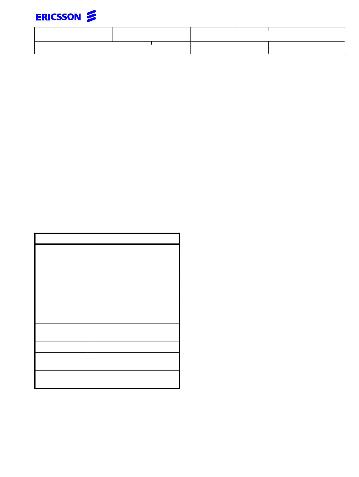
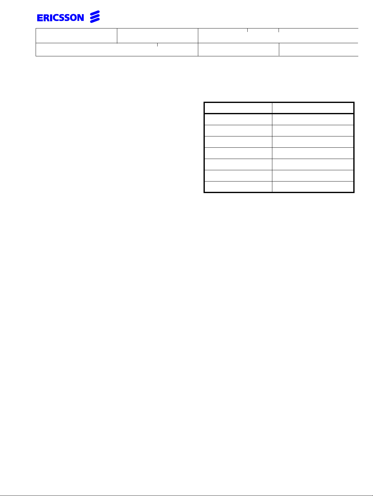
7.2 Traffic capacity
The traffic capacity of the Cordless part of the PBX is
mainly determined by the IC-CU_ and in exceptional
cases also by the Base Stations. The IC-CU can handle a maximum of 56 simultaneous calls and the ICCU2 can handle up to 60 simultaneous calls. Each
Base Station has a capacity of 8 simultaneous calls.
The traffic capacity of the IC-CU_ is determined by:
• the Grade Of Service (GOS) required by the
customer
• the number of speech circuits available, with a
limit of 64.
The Grade Of Service is the probability that acall is rejected because of system congestion. The customer
has to indicate which Grade Of Service is acceptable.
A Grade Of Service of 1%, or 0.01, means an average
of 1 lost call in every 100 calls. The IC-CU2 is
equipped with a SPU providing 8 speech circuits.
The two parametersmentioned above (GOS and the8
speech circuits) and the totalamountof traffic (Erlang)
that is required, are related to each other. The table
below shows the capacity at a required GOS.
This plug determines which maximum number of portables are allowed to be connected to the system. This
Page 28
Prepared
Subject responsible
INSTALLATION INSTRUCTION
Documentnumber
29(46)
1531-BDV BS 101 01 Uen
Doc respons/Approved Checked
Date
Rev
Reference
1998-05-29 L
Practically, this table is used to calculate from a given GOS and Erlang value the number of portable users.
IC-CU2
1
Speech Grade of service (GOS)
circuits
2% 1% 0.5% 0.1%
8 3.6 3.2 2.7 2.1
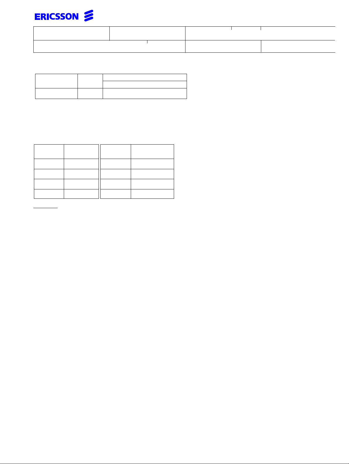
For the calculation it is necessary to estimate the time the portables actually make calls. The table below shows the
Erlang value depending on the estimated mean call-minutes fora portable telephone. These values may be different
between departments depending on their activities. These values multiplied by the number of portables result in a
traffic capacity that has to be provided.
mErlangMinutes
25015
30018
50030
75045
per hour
mErlangMinutes
per hour
503
1006
1509
20012
Example:
A customer ordering a system with 24 portable telephones. He estimates that each portable generates 200 mE
each in average. These values requirea system with a traffic capacityof3,6 E (0,15x24). With an acceptedGOS of
2.0% the traffic capacity can be met.
7.2.1 Traffic Capacity of Base Stations
A Base Station, having 8 channels available, has an Erlang value of 2.7 with a GOS of 0.5%. This means that each
Base Station can serve 18 portables, assuming each portable generates 150 mE during busy hour or 13.5 portables
generating 200 mE each.
Example:
Assuming a full coverage in a building canbeachieved with 2 Base Stations means that 20portables generate
together 20 x 0.150 = 3 E. Every Base Station has a traffic capacity of 2.7 Erlang. To have a sufficient
coverage two Base Stations covering the area of the busiest part of the company are needed.
Practically, the total capacity offered by the cordless network is generally more than sufficient, but this is from an average point of view. In certain places, traffic demands may vary such that locally the network is often blocked, or has
a lower GOS than required. For instance a purchase department may easily generate 300 mE per Portable during
busy hour, thus, when e.g. with 6 persons giving a very high load on the Base Station close by. It may be necessary
to add aBase Station in this areatohave enough capacityfor others to callas well. Also think ofe.g. canteens during
lunch time etc.
Page 29
INSTALLATION INSTRUCTION
Prepared
Subject responsible
Documentnumber
1531-BDV BS 101 01 Uen
Doc respons/Approved Checked
Date
1998-05-29 L
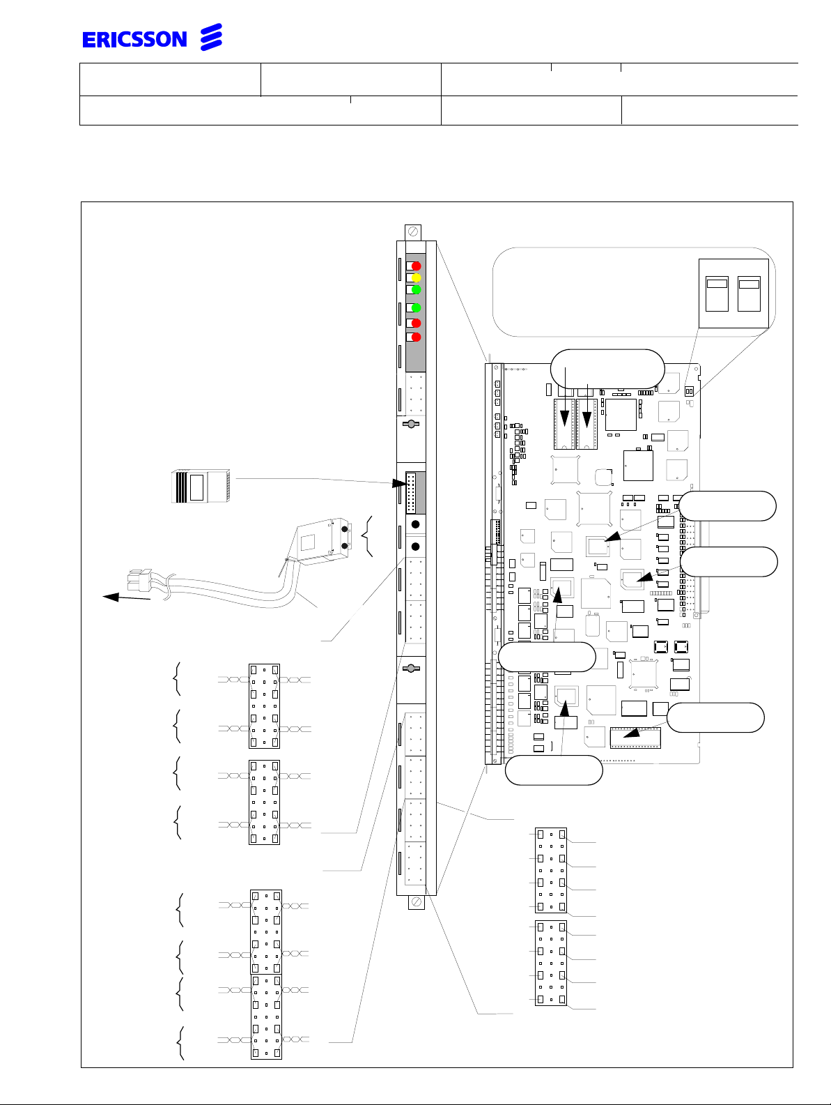
7.3 IC-CU2 (ROF 157 5131/_) (GAP-Protocol)
LEDs
Rev
30(46)
Reference
RP error
Individual blocked
Individual busy
CPU error/DCT error log
SPU error
DECT Sync port
SYNCH A IN
SYNCH B IN
SYNCH A OUT
SYNCH B OUT
CLU error
0 V
0 V
(KDU 130 05/__)
External power input
via front connector (to enable
set switch 1and 2 to OFF)
to power supply BML 351 048
Express Power feeding to base stations
(-)
To BS 4
EPP
TSR BS 101 12/1500
AC
18
20
22
(-)
To BS 3
EPP
EPP
EPP
(+)
(+)
red
yellow
green
green
red
red
V0
V1
(-)
(+)
BS2 9727
IC-CU2
R1A
ROF1575131/1
Switch 1 and 2 must have the
same position. ON (default)
48V from the backplane. OFF
activatesexternal DC inputand
disconnects the backplane.
RYS 102 531/1
DECT
synchronization
RYSNB 101 19
RYS 102 531/2
+
RYS 102 553/1
ON
1 2
ON
RYS 102 554/1
RYSNB 101 20
24
To BS 2
EPP
26
(-)
28
To BS 1
EPP
30
(-)
32
Serial communication to base stations
AC
To BS 4
SC0
02
04
06
To BS 3
SC0
08
To BS 2
SC0
10
12
14
To BS 1
SC0
16
EPP
EPP
(+)
(+)
SC1
SC1
SC1
SC1
RYSNB 101 23/2
Maintenance port
TXM
0 V
RCV
n.c.
TXM
0 V
RCV
DSR
18
20
22
24
26
28
30
32
RTS
DTR
PRINTER
DCD
PORT
CTS
RTS
DTR
MAINTENANCE
DCD
PORT
CTS
remove paper
insulation
Page 30

Prepared
Subject responsible
INSTALLATION INSTRUCTION
Documentnumber
31(46)
1531-BDV BS 101 01 Uen
Doc respons/Approved Checked
Date
Rev
Reference
1998-05-29 L
7.4 Base Station (KRCNB 201 03/_ and KRCNB 301 01/_)
The Base Station (BS) enables radio communication between the Integrated Cordless system and the portable
telephones. The communication via two2B+D interfaces, requires two twisted pair cables. Both interfaces provide in
total eight 32 kbit/s speech paths between a BS and IC-CU2, enabling a BS to handle eight simultaneous calls. The
BS is connected to the IC-CU2 via two wire pairs called serial communication wires (SC0 & SC1) carrying up to 8
simultaneousdigitalvoiceconnectionsandthecentralpowerfeeding.Apart fromdatacommunicationthesetwotwisted
pairs are alsobe used to distribute power to theBSs. Two additional pairs canbe wired to provide agreater powering
range. There are three methods to power BSs:
1. centrally via backplane (with or without EPP)
2. centrally via external input (with / w.o EPP)
3. via local power supply (optional).
With the first and second methods power is distributed via the IC-CU2 to the BS. The cable length between BS and
IC-CU2 depends on thenumber wires used for power feeding,the type of cable and environmentalnoise. In the third
case (local feeding),BSs are powered by anAC-adapter or another power source which isnot routed via the cabinet.
The number of BSs used in a system depends on the area to be covered and the traffic density. Typical in-house
coverageis upto 30meter radius.In practicethecell sizemayvary between10 metersindoorsin worstcasesituations,
up to 300 meters outdoor in free space.
The BS has two main functions:
• to modulate a carrier with the digital encoded information (TDMA frame directed to portable)
• to demodulate a modulated carrier (TDMA frame received from portable).
A special cover (KRY NB 101 01) is available to mount the BS (KRCNB 201 03) outdoors providing splash proof
housing and water tight sealings for the wiring.
7.4.1 Base Station Planning
The major task when providing a wireless service is to estimate the number of BSs and to find their most suitable
location. A number of factors tend to limit the range of a BS like the materials the wall is composed of or the location
and size of machines, furniture, air-conditioning systems, elevators etc. This results in unexpected reflections or
absorption of radio waves. Generally BSs should not be located on outer walls, except if the outdoor area has to be
covered as well, as this reduces the area actually covered. All of these unpredictable influencing factors makes it
extremely difficulttodefine rules for how to cover an areawith a suitable number of BSs.In difficult environments the
use of a site survey tool (LTT NB 101 01/_) is recommended.
Establish a Base Station plan for the installation site to determine the best location for the BSs.
Base Station aerial range
• Inan officeenvironment in asteel concretebuilding up to30 mindiameter canbe coveredand including,
under normal conditions, the neighbouring floors.
• Production halls up to 200 m in diameter are covered but ranges can be less if bulky machines, cranes
etc. are part of the interior.
• Outdoor ranges can be up to 300m.
When installing a BS, position it, then walk around to determine cell coverage area either by listening to the speech
quality- whethermutesor cracklingsounds areheardin theportable -or measuretheRQIindicator usingtheportables
Service Display facility (see FAULT TRACING 1545-ASB15002Uen).
Page 31

Prepared
Doc respons/Approved Checked
Subject responsible
INSTALLATION INSTRUCTION
Documentnumber
1531-BDV BS 101 01 Uen
Date
Rev
Reference
1998-05-29 L
32(46)
16m
intermediate
floor
Ground floor
3,5m
e.g. 40m
corridor
Base
Station 1
7.4.2 Base Stations Cabling
Usinga four-paircable ormore-pair cable,the freecablepairs canbeused asadditionalpower wires(EPP)to increase
the feeding distance andreduce overallpower consumption(by reducingthe ohmic resistance)to theBS. The BScan
also be powered by an on-site adapter (refer to section 7.4.7).
Connection of serial communication wires and EPP lines is polarity-independent. SC0-0 and SC0-1 may be
interchanged but SC0-xandSC1-x may not be interchanged. The diagrambelow shows the wiring principle to each
base station connected to the IC-CU2.
Power feeding of the Base Station
There are three alternatives to power feed (-48V) the Base Station:
• Thepower feeding canbe takenvia the IC-CU2from the backplane in thecabinet. TheDIP-switch on the
IC-CU2 is set to OFF.
• From an external power source via the front connector on the IC-CU2 (≤56V). Note the polarity on the
input (see drawing of IC-CU2 board). The switch on the IC-CU2 is set to ON.
• By an AC-adapter (see page 38). The switch on the IC-CU2 should be set to ON but
no power feeding from an external power source via the front connector on the IC-CU2.
Page 32

Prepared
Doc respons/Approved Checked
Subject responsible
INSTALLATION INSTRUCTION
Documentnumber
1531-BDV BS 101 01 Uen
Date
Rev
Reference
1998-05-29 L
33(46)
+
SC0-a
SC0-b
SC1-a
SC1-b
EPPa
EPPb
+
DC
DC
-
-48V from
backplane
CLC x
(one of 4
S1 & 2
+
T
-
48Vexternal
V0
source
+
V1
(optional)
SC0-a
SC0-b
SC1-a
Data/power
connector 1
up to 2 power pairs "EPP
carrying V0- and V1
or 8)
+
IC-CU2
T
SC1-b
EPPa
EPPb
Data/power
connector 2
available only on
Base Station
KRC NB 30101/_
SC0-a
SC0-b
SC1-a
SC1-b
EPPa
EPPb
Base Station KRC NB 201 03/_
and KRC NB 301 01/_
7.4.3 Base station cable delay measurement
After all base stations have been installed, the cable delays must be measured in order to program the base station
delaysinto thesystem atinitializationtime.OnIC-CU2s withtherevision R1Candhigherautomaticdelaymeasurement
is performed. In this caseno measurement is needed but using the cordless systemmanager (CSM) go to the menu
"add Base Station" and enter a "1" in the field "delay".
7.4.4 Ranges on cables
Thefollowingrangesare givenforbase stationsconnected toan IC-CU2.Dependingon thecable typerangesdepend
on noise levels imposed on the cables. The values stated are maximum achievable ranges:
Type Cable
Wire diameter (∅)
Twisted pair 0.4 mm 45 nF/km 1.2 km 1.0 km
Twisted pair 0.5 mm 45 nF/km 1.6 km 1.4 km
Twisted pair 0.5 mm 120 nF/km 0.9 km 0.8 km
Twisted pair 0.6 mm 45 nF/km 1.9 km 1.7 km
Twisted pair 0.6 mm 120 nF/km 1.1 km 1.0 km
Double twisted pair
(J-Y (St)Y 2×2×0.6)
0.6 mm 120 nF/km 1.0 km 0.9 km
Capacitance
Maximum cable length
Superimposed noise
8 mV/pHz 10 mV/pHz
Page 33

Prepared
Subject responsible
INSTALLATION INSTRUCTION
Documentnumber
34(46)
1531-BDV BS 101 01 Uen
Doc respons/Approved Checked
Date
Rev
Reference
1998-05-29 L
7.4.5 Base Station (KRC NB 203 01/_)
The Base Station (BS) is supplied with a drilling template to mount the unit and 2 antennas with TNC connectors.
Mount the unit in a suitable location to provide the best communication coverage.
Use the supplied drilling template and mount the BS with four screws (6 mm Φ). Complete the electrical connection
according to the above drawing. Do not connect to the Base station yet.
IF power is supplied by the adapter (BMLNB 101 04), the screw/slide connector must be used. The serial
communication wires can be connected via the modular jack or the screw/slide connector. A screw with a bundling
cord holder is provided for traction relief to the left of the connection field.The BS starts up if the supply lines deliver
more than 12 VDC.
LEDs
X52
RJ 45
modular jack
TNC connector
Power
Reset
(v0)
(v1)
EPP
EPP
SC1-a
1
SC0-a
SC0-b
X51
SC1-bncnc
Status of LEDs
Power LED on (green)
Reset LED on (red)
LED1 and LED2 on or
Mounting
holes (4x)
LED1 and LED2 flashing
LED1 and LED2 off
LED1 off and LED2 on
LED1 on and LED2 off
LED 2
LED 1
1
2345
or
SC1-a
SC0-a
SC0-b
67
8
(v0)
(v1)
EPP
EPP
SC1-bncnc
screw/slide
connector
Use connectors 5 & 6 for AC adapter
connection. This input is insensitive to
polarity reversal
Meaning
BS power on
Power Fail/Reset
BS in non
operational mode
BS operational (no traffic)
BS operational (traffic)
Fatal software error
Note: ) If theBase Station (KRCNB 201 03/_)is accessibleby persons otherthan trainedpersonnelmount thecover
(SDFNB 101101/_ or similar.
Page 34

Prepared
Doc respons/Approved Checked
Subject responsible
7.4.6 Base Station (KRCNB 301 01/_)
LED2
INSTALLATION INSTRUCTION
Documentnumber
1531-BDV BS 101 01 Uen
Date
Rev
Reference
1998-05-29 L
35(46)
Front view
SC = Serial Channel
EPP = Express Power Pair
NC = Not connected
LED1
RJ 45
modular jack
(v0)
EPP
(v1)
EPP
SC1-a
SC0-a
SC0-b
SC1-bncnc
Rear view
Factory testing
(RJ45)
Data/power
(RJ45)
Data/power
(RJ45)
The BS is connected to the radio exchange by means of a standard twisted pair cable. The BS is can be fixed to a
wall, a ceiling, a pole or a beam, by means of the mounting bracket included. When fixing the BS to a wall or ceiling
the included plugs and screws must be used. When fixing it to a pole or beam a (not included) strap a flexible metal
band must be used.
Connectors
• Two 8-pin RJ45 modular jacks for data and powering
• A 6-pin RJ45 modular jack for factory testing
The two data/powering connectors are interconnected on the board.
LEDs
LED 1: Green power LED
LED 2: Three colour LED, see table below
Status of LED2 Meaning
Off Base station operational and no traffic on the base station
Green Base station operational and traffic on the base station
Red Base station is malfunctioning
Amber Basestation is OK, but not available (self-test, notinitialized,
Flashing green All 8 channels are in use
Flashing amber Software is being downloaded to the base station
no communication with radio exchange)
Page 35

Prepared
Subject responsible
INSTALLATION INSTRUCTION
Documentnumber
36(46)
1531-BDV BS 101 01 Uen
Doc respons/Approved Checked
Date
Rev
Reference
1998-05-29 L
TheBSs canbemountedvertically orhorizontally. Mountthe BSsat placesand positionsas determinedin thesystem
configuration plan. The BS must be placed such that it is not facing large metal objects such as large heating pipes,
machines.
Fixing the mounting bracket to a wall
Fix the mounting bracket (see figure below) to the wall as follows:
1. Hold the mounting bracket with its flat side against the wallsuch that the text ‘TOP’ is the right way up,
and mark the two holes. The minimum distance between the upper hole and the ceiling or any object
above the BS must be as least 65 mm. If the distance is less than 65 mm, the BS cannot be slid onto
the bracket.
2. When using wall plugs, take a ∅ 6 mm drill and drill the two holes and insert the included wall plugs.
3. Position the mounting bracket with its flat side to the wall and fasten it with the two included ∅ 3.5 mm
screws.
Ceiling
≥ 65 mm
TOP
Fixing the mounting bracket to a pole or beam
The mounting bracket can befixed to a pole (diameter ≥ 45 mm) or a beam (wider than 50 mm) by means of a strap
or flexible metal band less than 30 mm wide. Fix the mounting bracket to a pole or beam such that the text ‘TOP’ is
right way up. The strap or flexible metal band must be purchased locally.
Tied wrongly
Page 36

Prepared
Doc respons/Approved Checked
Subject responsible
Cable ducts
65 mm
57 mm
TOP
125 mm
INSTALLATION INSTRUCTION
Documentnumber
1531-BDV BS 101 01 Uen
Date
Rev
Reference
1998-05-29 L
Whenthe BSis mountedto thewall, cableductscan
be used to route the wiring through.
• Fix the cable duct to the wall in one of the
positions shown in left figure.
• For safety reasons secure the BS cable to a
convenient point at about 30 cm from the base
station.
If for somereasonthe BS drops, the cable is pulled
out of the base station.
37(46)
75 mm 70 mm
Mounting the Base Station
1. Hold the BS flat against the mounting bracket and move it downwards until it clicks.
Note:Aftercompletion ofthe installation,base stationsmust beinitializedusingthecordlesssystemmanager.
15 mm thick cable ducts
Page 37

Prepared
Subject responsible
INSTALLATION INSTRUCTION
Documentnumber
38(46)
1531-BDV BS 101 01 Uen
Doc respons/Approved Checked
Date
Rev
Reference
1998-05-29 L
7.4.7 Power Feeding of Base Stations
When using any of the adapters mentioned below care must be taken to configure the IC-CU2 boards for local BS
feeding. If the BSs are to be fed locally the remote power feeding switch on the boards should be set to the position
disconnecting the feeding from the back plane and no external feeding to the board should be connected.
Adapter for Base Station (KRCNB 201 03/_)
An AC-adapter to feed the BS locally is available for 230VAC/24VDC (BMLNB 101 04) for all European countries except UK and Cyprus. In other countries this has to be purchased locally and must meet the specifications given below:
Output voltage: between 12 V and 56VDC
Output power 7,5W minimum
Adapter for Base Station (KRCNB 301 01/_)
The 24 VDC adapter (BMLNB 101 09/n) is fittedwitha 8-pin RJ45 plug that can be plugged into one of the data/power connectors of the base station.
7.4.8 Software upgrade
If necessary, the software in the BS can be updated by downloading new software to the BS. Downloading can be
performed without disconnecting the BS. The new software is stored in flash memory.
Page 38

Prepared
Subject responsible
INSTALLATION INSTRUCTION
Documentnumber
39(46)
1531-BDV BS 101 01 Uen
Doc respons/Approved Checked
Date
Rev
Reference
1998-05-29 L
8 LINE NETWORK
The line network for PBX-extensions is to be installed in accordance with the stipulations for standard telephone
networks. Twisted pair cables must be used for the lines and a wire diameter 0.5 mm is recommended in order to
reach full line length,
i.e. 800 m.
No stubs and/or branchesmay exist on a digitalextension lines, as they could causetransmission problems.
• The network lines are to be connected directly to the internal Krone MDF with prefabricated cables (TSR BS
902 0001/800) leading to the boards.
• In case a separate Ericsson MDF has to be installed, prefabricated cables are used between the MDF and
board connectors in the exchange cabinet.
These cables have EURO-connectors mounted at one end for connection to the board.
For connection of ELU-A, ELU-D, BTU-A, BTU-C or BTU-E to the internal MDF use the following cable:
• TSR BS 902 0001/800 is terminated on the board side with standard Ericsson connectors and Krone
connectors on the other side.
For connection of ELU-A, ELU-D, BTU-A, BTU-C or BTU-E to a external MDF use following cables:
• TSR 902 0472/3 (length = 6 m) is equipped with connector only at the exchange side
• TSR 901 0472/2 (length = 15 m) is equipped with connector only at the exchange side
For connection of BTU-D, use the following cable:
• TSR 225 1304/20000, 75 Ω coaxial cable
• or use the same cable as for BTU-A for 120 Ω connection or a double shielded cable TSR 901 0481/20000
(adhere to local requirements).
The cables run into the exchange from below the cabinet.
The cables from the line network are led directly to the MDF in the exchange cabinet.
Secure the cables to the exchange cabinet with the adhesive anchors and bundling cord.
Page 39

Prepared
Doc respons/Approved Checked
Subject responsible
8.1 Cables for BDV 113 08
8.1.1 MDF cables Krone
INSTALLATION INSTRUCTION
Documentnumber
1531-BDV BS 101 01 Uen
Date
Rev
Reference
1998-05-29 L
40(46)
AB
a02
ind. 1
(wt) a
(bl) b
(wt) a
(or) b
A
(wt) a
ind. 3
(gn) b
ERICSSON MDF bar
connections see above
Open ends
(wt) a
(br) b
wire wrap side
AB
ind. 2
ind. 4
B
ind. 5
ind. 7
Factory Year-W-D R-state
Factory Year-W-D R-state
(rd) a
(bl) b
(rd) a
(gn) b
a10
(rd) a
(or) b
(rd) a
(br) b
ind. 6
ind. 8
C
colour: wt bl wt or wt gn wt br rd bl rd or rd gn rd br
ab
1 2
ind.1 ind.2 etc.
1234567890
ab ababababababababab
ababab
3
4 65
C
ab
ab
a
slotting side
ind. 1 ind. 2 ind. 8
C
AB
connections see above
part number
TSR BS 902 0001
/800
/1500
/3000
TSR 902 0444/1
TSR 902 0444/2
TSR 901 0472/3
Factory Year-W-D R-state
length a
a
usege
800 mm standard cable for integrated MDF
1500 mm standard cable for external MDF
3000 mm
MDF cable for existing MDF
1500 mm standard cable for external MDF
3000 mm standard cable for external MDF
6000 mm
15000 mm
for external MDF, 120Ω for BTU-D
standard cable for external MDFTSR 901 0472/2
Cable with 8 pairs, mounted with:
ERICSSON plug and
Krone bar.
ERICSSON plug
and ERICSSON MDF distribution bar
ERICSSON plug
and open ends
Page 40

Prepared
Subject responsible
Doc respons/Approved Checked
8.1.2 Coax cable for BTU-D
INSTALLATION INSTRUCTION
Documentnumber
1531-BDV BS 101 01 Uen
Date
Rev
Reference
1998-05-29 L
41(46)
B
part number
TSR 225 1304/20000
8.1.3 V.24 cables
A
B
A02
A04
A
A06
A08
C02
C04
C06
C08
length a
length a
a
usege
20000mm coax cable 75 Ω for BTU-D
25 14
C
TXD
A02
0V
A04
RTS
C02
DTR
C04
A06
C08
A08
RXD
CTS
DSR
C
c06
only on TSR 902 0466
113
TXD
3
7
5
6
2
4
20
A02
0V
A04
RTS
C02
DTR
C04
A06
C08
C06
A08
RXD
CTS
DCD
DSR
C
2
7
4
20
3
5
8
6
part number
TSR 902 0476/1
Wiring of cables: Wiring of cable:
a
usege
TSR 902 0448
5000mm cable connecting a PC to CPU-D_/AUXTSR 902 0448/1
5000mm cable connecting a modem to CPU-D_/AUXTSR 902 0466/1
5000mm cable connecting a printer to CPU-D_/AUX
TSR 902 0466TSR 902 0476
Page 41

Prepared
Doc respons/Approved Checked
Subject responsible
8.1.4 Battery connection cable
length a
INSTALLATION INSTRUCTION
Documentnumber
1531-BDV BS 101 01 Uen
Date
Rev
Reference
1998-05-29 L
Factory Year-W-D R-state
42(46)
part number
part of NTM BS 101 02
8.1.5 Mains power cables
Cable for EUROPE
part number
RPM 945 323
Cable for U.K.
a
usege
230mm Battery connection cable
length a
a
usege
2500mm mains power cable 230V 10A
part number
RPM 945 326
length a
a
usege
2500mm mains power cable 250V 10A
Page 42

Prepared
Doc respons/Approved Checked
Subject responsible
Cable for Brazil, Mexico, Venezuela etc.
length a
INSTALLATION INSTRUCTION
Documentnumber
1531-BDV BS 101 01 Uen
Date
Rev
Reference
1998-05-29 L
43(46)
part number
RPM 945 324
a
2500mm mains power cable 125V 10A
Cable for Australia, New Zealand, China etc.
part number
RPM 945 311
a
2500mm mains power cable 250VAC 10A
Cable for Denmark
usege
length a
usege
length a
part number
RPM 945 327
Cable for Italy
part number
RPM 945 313
a
usege
2500mm mains power cable 250VAC 10A
length a
a
usege
2500mm mains power cable 250VAC 10A
Page 43

INSTALLATION INSTRUCTION
Subject responsible
DocumentnumberPrepared
1531-BDV BS 101 01 Uen
Doc respons/Approved Checked Reference
Date Rev
1998-05-29
L
44(46)
9 MARKING OF CABLES
Each cable that is connected to a PBX type ASB 150
should be marked on the cable’s designation holder
with the label set SVH 277 003/4, supplied for this
purpose. The cable TSR 902 0444/1issupplied with a
designation holder, 860 1839, at the EURO-connector.
BTU_
03
6
*
2
Front side of
designation
holderon cable
to PBA
This label set contains three label types:
Label 1: This label indicates the abbreviated name
Label 2:
Placing of PBA
in PBX
Label 1:
Type of PBA
Label 3:
Positionof pin
contact unit
on PBA
2
0 1 2 3 4
4
1st
1/4
2nd
1/4
3rd
1/4
4th
1/4
for the PBA to which the cable is to be
connected.
Example of parameter:
6
BTU_
10 INTERNAL MDF
(Main Distribution Frame)
The BDV BS 101 01 is factory equipped with a Krone
snap-in holder accommodating a maximumof 8 Krone
connectors, which can be snapped-in if desired. Use
pre-fabricated MDF cables (TSR BS 902 0001/800) to
connect the boards in the swivel shelf with the MDF.
The bottom row is intended for interconnections, e.g.
earth connection of the BTU-A_ to the incoming PTT
earth wires orconnections to the CPU I/Os.The Krone
connector above is reserved for the trunk lines that
can be equipped with surge protection.
Be sure to fasten the cable clip at the bottom of the
swivelshelf after installationbefore mounting the cover
of the swivel shelf.
An additional MDF holder is available and orderable
that can be mounted within the exchange in the space
provided for the battery case.
Place the cablesaccordingto the figure below.Secure
the cables to the MDF cabinet with adhesive anchors
and bounding cord.
NOTE: There must be a ground connection for
the MDF cabinet when surge protectors
are used.
Label 2: There is one 2-digit parameter.
This parameter indicates the position of
the PBA-slot in the PBA where the cable
is to be connected.
Example of parameter:
03
Label 3 There are two 1-digit parameters.
The first parameter indicates the position
of the pin-contact unit on the PBA.
The second parameter indicates the 1/4
of the pin contact.
Example of parameters:
6*2
These threelabels indicate where theupper part of the
cable is to be connected and are placed on the front
side of the designation holder.
When the label 1 for PBA has a "_" included in the
name, please enter the correct letter with a marker
pen.
Primarily intended
for trunk line use
(with surge protectors)
Cables for board
connections:
TSR BS 902 0001/800
Krone
connection
bar
Connections
of cables from
line network
Page 44

INSTALLATION INSTRUCTION
Subject responsible
DocumentnumberPrepared
1531-BDV BS 101 01 Uen
Doc respons/Approved Checked Reference
Date Rev
1998-05-29
L
45(46)
11 Door Interface Unit (DIU)
(BFY BS 10101/1)
Installation:
The DIU is an interface connected via one or two extension lines to the ELU-A of the exchange and via a
set of wires to the door phone. The DIU should be
mounted indoorsona dry wall. Thedoorphone can be
of any commercially available type as long as it meets
the requirements listed in the 1555-ASB15002Uen
SYSTEM OVERVIEW under section 7 Technical Data
for DIU.
Connection:
The wires to the speaker and microphone should be
via two twisted pairs in a separate cable. Caution
when connecting a polarity dependant microphone
check polarity on connector x1. In another cable make
the connections to the door bell button, door opener
and key lights etc. This is to minimise disturbances on
the microphone line. The wires to the door opener
carry more currentand should havea diameter greater
than 0,6 mm. Thelength between door phoneand DIU
should be less than 50 m. The length between door
phone and exchange should be less than 500m.
The connector X18 is used for speech connection between DIU and exchange. The connector X17 is used
to activate the door opener. If the door opener wiring
already exists the X17 connection can be omitted and
the connection X12 leads to a existing button.
Pressing the door phone button (connection X5) activates the DIU and the programmed extension rings
(see Facility Description 15534-ASB15002Uen). The
interface stays active for the preset time selected under "C" and shuts off after this time has elapsed.
sounds loudenough andclear otherwise repeat the
procedure.
• No voice connection to the speaker of the
telephone.Turn the mic potentiometer screw two
turns clock wise. Speak into the door phone
microphoneandverifythat itisheardinthe handset
of the telephone otherwise repeat again.
Settings on the board
OPENER
8 sec
6 sec
Ext. B
Ext. A
x17
x18
BELL
x5
K1
use cable diameter≥0.6mm
(lead directly to door opener
button if already wired)
DO
x12
Microphone sensitivity
level setting
A
MICLS
+
-
x2 x1
4 sec
TIMEOUT
1 sec
3 min
2 min
1 min
D
C
DIU (BFY BS 101 01)
Mic
-
B
Loudspeaker
Volume
+
mains
spkr mic
door phone
8...48VAC
Transformer
door
bell button
door
opener
TO
Extension
B (door
opener)
TO
Extension
A (voice)
11.0.1 Adjustments of DIU
The microphone level is factory set but under certain
conditions theline attenuationcan exceedexpectations
resulting only inone way speech connectionor clipping
of the voice between extension and door phone. In this
case cautious change of microphone level setting has
to be performed. The potentiometers range is
• If the voice inthe speakerof the doorphone sounds
too dim or is clipped turn the mic potentiometer
screw two turns counter clock wise. Speak into the
telephone microphone and verify that the speaker
Microphone connection with polarity dependent
A
6 VDC supply for microphones with amplifiers.
The loudspeaker volume level is factory set. To
B
adjust turn the Loudspeaker potentiometer.
Timeoutfortheinterfacetoshutoff.Thejumperse-
C
lects intervals between 1...2...3 minutes.
Set door opener activation time 1...4...6...8 sec.
D
Page 45

INSTALLATION INSTRUCTION
Prepared
Doc respons/Approved Checked
Subject responsible
Documentnumber
1531-BDV BS 101 01 Uen
Date
1998-05-29 L
Rev
12 INSTALLATION OF ALARM INTERFACE UNIT
Line to exchange
a
DBY BS 410 01/1
46(46)
Reference
a bnc ba bb nc
line to exchange
ba and bb are the
connectors to the
alarm button
nc are not used wires
wall outlet
RPM BS 130 002/01
a
connect to the line input on the telephone
Line/Alarm
1
Pin Description
not used
1
button a
2
a
3
b
4
button b
5
not used
6
The ALARM INTERFACE UNIT is an optional equipment mounted in the case bottom of the DBC 21x telephones.
This equipment is used in the hospitality area to enable distress notification from e.g. a bathroom. A normally closed
switch is installedand the two terminals are connected to the pins (buttona and button b) on the option unit.The connection can be made in the walloutlet then the wiring shown above applies. In caseof another type of wiring the connector Optional alarm can be used.
(to wall outlet)
RJ12
Line out
1
Pin Description
1
2
3
4
not used
a
b
not used
(to telephone)
RJ14
Optional Alarm
1
Pin Description
button a
1
not used
2
not used
3
button b
4
RJ14
Page 46

INSTALLATION INSTRUCTION
Prepared
SEA/EBBMP Stangelberger
Doc respons/Approved Checked
Subject responsible
SEA/EBBX/F
SEA/EBBMP ASB 150 02
Documentnumber
1531-BDV BS 101 05 Uen
Date
Rev
1999-07-15 A
Database reference
Reference
1531-BDVBS10105Uen-1-A.emf
INSTALLATION INSTRUCTION
EXCHANGE CABINET
BDV BS 101 05
1(48)
Page 47

INSTALLATION INSTRUCTION
Subject responsible
DocumentnumberPrepared
1531-BDV BS 101 05 Uen
Doc respons/Approved Checked Reference
Date Rev
1999-07-15
A
2(48)
Contents Page
1 GENERAL . . . . . . . . . . . . . . . . . . . . 3
1.1 Supplementary documents. . . . . . . . 3
1.2 Tools . . . . . . . . . . . . . . . . . . . . . . . . . 3
2 DECLARATION OF CONFORMITY4
3 HOW TO OPEN THE CABINET. . . . 6
4 INSTALLATION . . . . . . . . . . . . . . . . 6
4.1 Mounting of the cabinet . . . . . . . . . . 6
4.2 Safety and EMC . . . . . . . . . . . . . . . . 7
4.3 Access to the boards . . . . . . . . . . . . 7
5 POWER SUPPLY UNIT . . . . . . . . . . 8
5.1 Replacement of the power
supply unit . . . . . . . . . . . . . . . . . . . . 8
5.2 Power feeding with an external DC
supply . . . . . . . . . . . . . . . . . . . . . . . . 9
6 ALLOCATION . . . . . . . . . . . . . . . . . 9
6.1 Power supervision of ELU-A (ROF 157
5114/_) . . . . . . . . . . . . . . . . . . . . . . . 9
6.16 VMU-D (ROF 157 5117/1). . . . . . . 28
7 INTEGRATED CORDLESS. . . . . . 29
7.1 Board Descriptions . . . . . . . . . . . . 29
7.2 Traffic capacity. . . . . . . . . . . . . . . . 29
7.3 IC-CU2(ROF 1575131/_)(GAP-Protocol)
31
7.4 Base Station (KRCNB 201 03/_ and
KRCNB 301 03/_) . . . . . . . . . . . . . 32
8 LINE NETWORK. . . . . . . . . . . . . . 40
8.1 Cables for BDV 101 05 . . . . . . . . . 41
9 MARKING OF CABLES . . . . . . . . 46
9.1 External MDF SXK 106 4139/1 . . . 46
10 Door Interface Unit (DIU)
(BFY BS 10101/1) . . . . . . . . . . . . . 47
11 INSTALLATION OF ALARM
INTERFACE UNIT . . . . . . . . . . . . 48
6.2 Connection of CM-Boards . . . . . . . 10
6.3 System Power Consumption. . . . . . 10
6.4 BTU-A (ROF 157 5110/_) and
BTU-A2 (ROF 157 5120/_). . . . . . . 12
6.5 Power failure circuit (PFC) . . . . . . . 12
6.6 BTU-C (ROF 157 5111/_). . . . . . . . 13
6.7 BTU-B (ROF 157 5121/_). . . . . . . . 14
6.8 BTU-B2 (ROF 157 5121/_). . . . . . . 14
6.9 BTU-D (ROF 157 5112/1) and
REG (ROF 157 5112/2) . . . . . . . . . 16
6.10 BTU-E (ROF 157 5113/_). . . . . . . . 18
6.11 CPU-D_ (ROF 157 5118/_) and
AUX_(ROF157 5119/_). . . . . . . . . . 22
6.12 CPU-D4 (ROF 157 5124/_) . . . . . . 23
6.13 ELU-A and ELU-D . . . . . . . . . . . . . 24
6.14 MFU (ROF 157 5132/_) . . . . . . . . . 26
6.15 VMU-HD (ROF 157 5126/1)
(ROF 157 5126/3) w. Flash Card . . 28
Page 48

INSTALLATION INSTRUCTION
Subject responsible
DocumentnumberPrepared
1531-BDV BS 101 05 Uen
Doc respons/Approved Checked Reference
Date Rev
1999-07-15
A
3(48)
1 GENERAL
Exchange cabinet BDV BS 101 05 is designed to be
furnished with Printed Board Assemblies (hereafter =
boards or PBAs) belonging to ERICSSON’s PBXsystem ASB 150 02. System functions, desired by the
customer, are realised with appropriate boards and
system programming.
The PBXis powered by aswitched mode power supply
(SMPS) that is available for two voltage versions. The
standard version is an AC/DC converter. The version
with battery charger offers the same facility but additionally providesbattery back-upor can be poweredby
an external DC-source. The SMPS for 230V is addi-
tionally available with power factor correction (PFC).
Due to the limited load of the cabinet’s power supply
units, the definitive board configuration in a cabinet
must follow the prerequisites in section 6.3.
After installation the PBX shall be made operational in
accordance with the stipulations that apply for system
ASB 150 02. See document START OF OPERATION
(1537-ASB 150 02). The cabinet is adaptedfor boards
fitted with brackets containing screws. Only boards
equipped with these brackets must beinstalled. These
screws must always be fastened to ensure a proper
ground connection.
Every cabinet’s board position could be used for arbitrary furnishing with boards belonging to PBX system
ASB 150 02 but the first position in the first cabinet
must be reserved for the CPU-D_.
It is advisable to protect trunk lines with extra
overvoltage protectors, especially in geographical
areas that are highly exposed to lightning.
1 A protective resistor of 10 Ω/1W
(REN 195 42/1) connected in series
between cabinet and MDF
2 An overvoltage arrester (gas discharge
tube) for quenching surges to protective
ground shouldbe installed onthe network
side of the protective resistor.
businessphone
MDF
Overvoltage arresters
Protective
resistors 10 Ω/1W
(REN 195 42/1)
Protective
ground
(NGC 402 01)
Housed in:
overvoltage protection
cassette (769 027/3)
Note: Make sure the MDF is really connected
to protective ground.
Figure: Line protection
1.1 Supplementary documents
• Document collection EN/LZB 103 1233
• INSTALLATION INSTRUCTION
(1531-BML BS 101 01) for the power supply,
equipped with battery charger
Any lines connected to the PBX that are subjected to
excess voltage (transients) in conjunction with e.g.
lightning discharges must be equipped with excess
voltage protection, refer to figure: Line protection. The
excess voltage protection can not be installed inside a
BDV BS 101 05 cabinet but should be mounted in an
integrated or external MDF.
Special precautions must be taken to analogue
extension lines that are led outdoors, in order to
prevent the analogue extension boards secondary
protection device from blowing in case of lightning.
Each branch on the extension line must have:
1.2 Tools
In addition tocustomary installation tools,the following
is recommended:
• Use theappropriate connectiontool 769027/2 to
connect the cables in the internal MDF.
• Use the appropriate slotting tool LSY138 252 to
connect the cables to the external
MDF SXK 106 4139/1.
• Board extractor for PBAs (handle LTD 117 02
and bottom LTD 117 12)
Page 49

INSTALLATION INSTRUCTION
Subject responsible
DocumentnumberPrepared
1531-BDV BS 101 05 Uen
Doc respons/Approved Checked Reference
Date Rev
1999-07-15
A
2 DECLARATION OF CONFORMITY
4(48)
This page is left blank for the CE-document. Use the link to read the document.
Page 50

Prepared
Doc respons/Approved Checked
Subject responsible
INSTALLATION INSTRUCTION
Documentnumber
1531-BDV BS 101 05 Uen
Date
Rev
Reference
1999-07-15 A
5(48)
This page is left blank for the CE-document. Use the link to read the document.
Page 51

INSTALLATION INSTRUCTION
Subject responsible
DocumentnumberPrepared
1531-BDV BS 101 05 Uen
Doc respons/Approved Checked Reference
Date Rev
1999-07-15
A
6(48)
3 HOW TO OPEN THE
CABINET
Unpack the exchange cabinet.
Check that everything has been received according to
the delivery note and that nothing has been damaged
during the transport.
The cabinet cover is latched. To open reach inside the
center cable duct from below and push lever up gently
to unlock then remove the cabinet’s front cover. For
details of the bottom view of cabinet see page 8.
businessphone
4 INSTALLATION
The PBX can be delivered as a customer configured
unit or the add-in boards can be delivered separately.
The cabinet is always equipped with a power supply,
suitable for the local mains. Please check the label
stating the permitted mains voltage. The cabinet is to
be mounted on an indoor wall. A mains outlet must be
provided near the equipment and shall be easily
accessible. Connection to earth (refer to 4.2) is
necessary for safe operation to discharge lightning
strikes. The premises shall comply with the following
prerequisites:
• The air shall be free from dust and smoke
• Environmental conditions according to
ETS 300 019 (1-4) (Temperature shall be
between + 5°C and +40°C and relative humidity
may vary between 15% and 80%)
• The PBX shall not be exposed to direct sunlight
4.1 Mounting of the cabinet
2
1
1
Lift latch to release the cabinet cover
2
Then remove the cabinet cover.
Overall dimensions of the cabinet:
• 400 x 500 x 155 (H x W x D in mm).
Attach the proper label at the bottom of the cabinet
before hanging up the cabinet (refer to section 4.2 on
page 7 for the position). The label must comply to the
SMPS installed and the local mains voltage level.
The cabinet’s wall mountingplate is locatedon the rear
of the cabinetduring transport. Take into consideration
the normal working height above the floor (about 1.30
m to the lower edge of the cabinet) and leave enough
room for access on both sides of the cabinet. To pull
out thecabinet’s wall mountingplate remove thescrew
C below the swivel shelf (refer to next page). Then
position the mounting plate where you want to mount
the cabinet, markand drill three 8 mmholes. Insert the
enclosed wall plugs and screw tight the cabinet’s wall
mounting plate.
TOP
Screw hole for screw (C)
to hold
wall mounting plate
during transport
figure: wall mounting plate
Page 52

INSTALLATION INSTRUCTION
Subject responsible
DocumentnumberPrepared
1531-BDV BS 101 05 Uen
Doc respons/Approved Checked Reference
Date Rev
1999-07-15
A
4.2 Safety and EMC
7(48)
To fulfil electrical safety requirements IEC 950 and
EN 60950, the exchange must be connected to
protective earth via a flexible wire with a cross
sectional area of at least 6 mm2.
Local requirements shall be adhered to.
The electrical connection must be carried out by
authorised personnel.
A
B
Shelf
cover
Turn
out
SWIVELSHELF
C
PSU
A
snap-on
wrist strap
Connection
for protective
earth
cross sectional area greater than 6 mm
2
connector
Attach label delivered with the PSU!
168
Label: LZFBS 083 013/3L03
Note: The mains current rating stated on the label is the
maximum current of the charger version.
Latch to release cover
Bottom view of cabinet BDV BS 101 05
All line interfaces in the PBX are protected in
accordance with K.21 (voltage transients up to 1.5kV).
BTU-A, BTU-A2, BTU-B, BTU-C, BTU-D, BTU-E and
MFU are working with interface TNV.
All other boards and the V.24 port work with interface
SELV.
4.2.1 EMC
The ferrites, with the ERICSSON ordering number
STF 82 601, should be situatedclose to the slot where
the cablesare led outof the cabinet.Two turns through
the ferrite core are sufficient to comply with EN 55022
Class B and to avoid disturbances in non-industrial,
residential (home) usage.
to protective earth
NOTE:If the earth is not connected,
a possible strike of lightning
might cause a fire!
Remove this screw located behind the swivel shelf
C
to access the wall mounting plate
Before operating, make sure that the chassis is
connected to a hard-wired protective earth.
Note: The wrist strap must have a 1MOhm series
protection resistor to comply to the safety
standards. If this resistor is missing, then
accidentally touching live wires can be leathal.
4.3 Access to the boards
NOTE:
Turn out the transport screws (A)about 1 cm at thetop
and bottom of the swivel shelf. See figure in section
4.2. Hold the bottom of the shelf, lift the shelf slightly
and turn the swivel shelf counter clockwise(ccw). Turn
the screw (B) two turns at the top of the shelf cover
and remove the cover.
Makesure thatasound groundconnection to
the exchange has been established. Otherwise this can be hazardous in case of lightning. Use a grounding wrist strap when
handling PBAs sensitive to electrostatic discharges.
Page 53

INSTALLATION INSTRUCTION
Subject responsible
DocumentnumberPrepared
1531-BDV BS 101 05 Uen
Doc respons/Approved Checked Reference
Date Rev
1999-07-15
A
8(48)
5 POWER SUPPLY UNIT
The SMPS for the cabinet are AC/DC switch mode
power supplies complying to ETS 61 000-3-2 (power
factor correction but only for the 230V version) for two
mains voltages. Pleasecheck whether the label states
the proper mains voltage as required. For mains with
230V to 250V AC, two versions are available:
• BML BS 101 02/1 (PSU 230V standard)
• BML BS 101 02/3 (PSU 230V std. w. PFC)
• BML BS 101 01/1 (PSU 230V equipped with
battery charger).
• BML BS 101 01/3 (PSU 230V equipped with
battery charger and PFC).
For mains with 115V to 127V AC two versions are
available:
• BML BS 101 02/2 (PSU 115V standard)
• BML BS 101 01/2 (PSU 115V equipped with
battery charger).
The PSUs deliver 30 W on the PBA supply voltages
and 101 W on the 48 V supply voltage.
Warning: The power switch does not disconnect
from mains. The mains cord must be unplugged to
disconnect the mains.
5.1 Replacement of the power supply unit
On delivery the PSU isalready installed in the cabinet.
The procedure of how to dismount the unit is
described below.
a Switch off the PSU (A) and unplug the mains
from the wall outlet. If the unit is a PSU with
battery charger, disconnecttheDC supplyline to
the batteries andunplug the alarm connector on
the unit.
b Disconnect the DC supply cord (D) from the
swivel shelf.
c Unscrew the transport screw (B).
d Push the PSU from the bottom and turn out the
PSU clockwise, unhinge and take it out. Then
pull off the mains plug at the bottom of the PSU
and disconnect the ground wire.
e Install the PSU in the reverse manner.
When installing a power supply unit with battery charg-
er and the backup battery, please refer to the INSTAL-
LATION INSTRUCTION (1531-BML BS 101 01).
The PSU is equipped with a mains fuse rated
250VAC 6,3 A T.
NOTE: This fuse NGH 258 03/630 can be ordered
from Ericsson but is a non-accessible and non-user
serviceable part. Only authorised personnel is
allowed to change the fuse. Contact the local
supplier in this matter.
Battery backup time
The power consumption of the telephones and base
stations on the 48 V should be less than 2.1 A for all
PSU types.The batteries inthe integratedbattery case
have a capacity of 2Ah. Using fresh batteries, a
backup time of 20 minutes is guaranteed and
depending on the system configuration even longer
backup times might be achieved.
(D)
Power switch
does not
disconnect
unit from
mains.
Standby only
Ground
(A)
(B)
Label
Mains power cord plug
IEC 320 C17
Page 54

Prepared
Subject responsible
INSTALLATION INSTRUCTION
Documentnumber
9(48)
1531-BDV BS 101 05 Uen
Doc respons/Approved Checked
Date
Rev
Reference
1999-07-15 A
5.2 Power feeding with an external DC supply
When the PBX is supplied with power by an external battery with 48V nom. (44 - 56V), the installation of a power
supply equipped with a battery charger (BML BS 101 01/_) is required. The DC supply is connected directly to the
PSU.
An externally accessible fuse 250VAC 6,3 A T isprovided on the PSU,but additionally a fuse must be installed in the
supply line with DC current switching capability greater than 160 A.
Note: To prevent arcing never connect the DC source when the PSU has not started-up.
Use the mains to power up or use an external switch to connect the DC source. This is a precaution to minimise the
contact loads on the plug. For further details see INSTALLATION INSTRUCTION (1531-BML BS 101 01).
As battery operation often requires different preconditions, only an overview can be provided with regard to battery
capacity/charging capacity. The batteries shouldbe supplied locally. The type isdescribedin detail in INSTALLATION
INSTRUCTION (1531-BML BS 101 01).
6 ALLOCATION
In principle, all board positions in cabinet BDV BS 101 05 can be used for arbitrary configurations with PBAs
belonging to PBX-system ASB 150 02.
The boards are equipped with ground brackets on the top and bottom. Make sure to fasten the boards with the
supplied screws during installation.
There arerecommendations for configurationsin order to simplifyoperation and maintenance.For further information
see document collection EN/LZB 103 1233.
Sub-equipped boards:
Install sub-equipped boards in the last position after the standard boards to enable easy upgrading without having to
re-number trunks and extensions.
6.1 Power supervision of ELU-A (ROF 157 5114/_)
The board is equipped with an automatic traffic limiter restricting the internal power dissipation on the board to a
maximum of 12W. This depends on both the line length and the number of lines busy.
If the power consumption exceeds the limit, no further lines can access service, and at least two lines have to go on
hook, for all lines to work normally again.
When connecting external voice systems a maximum of 8 lines are recommended on each board. The remaining
lines on the board are to be connected to low-traffic extensions.
Page 55

Prepared
Subject responsible
INSTALLATION INSTRUCTION
Documentnumber
10(48)
1531-BDV BS 101 05 Uen
Doc respons/Approved Checked
Date
Rev
Reference
1999-07-15 A
6.2 Connection of CM-Boards
Connect the correct type of call metering board, according to the figure below, on BTU-A board ROF 157 5110/_ or
ROF 157 5127/_ and in the same fashion on the BTU-C board ROF 157 5111/_. The BTU-C cannot be equipped
with a CM50 board as the flat ribbon cable cannot be connected and CM12/16 (ROA 219 5135/1).
Line 0 - 1
CMboard
Line 2 - 3
Note: When installing a CM50-board connect the
cable before mounting the CM50-board. The
BTU-A board must also be connected to
Line 4 - 5
earth.
The following boards are available CM50 ROA 219 5064/1, with flat ribbon cable and CM12/16 ROA 219 5135/1 or
ROA 219 5062/1 without cable.
6.3 System Power Consumption
The power demand of the system comprises the sum of the current demands of all extensions, base stations etc.
This total current has tobe delivered by the power supply. Choose the one delivering therated current with a suitable
margin for add-on equipment depending on the installation site.
6.3.1 Base Station Power Demand
To minimise the power dissipation on the serial communication wires, EPP should be used extensively. Up to 4 BS
can be connected to the IC-CU2.
The total 48 VDC current load of the BS on the power supply has to be calculated as follows:
Cable
length
0m
100m
200m
300m
400m
500m
600m
700m
800m
900m
1,0km
1,1km
1,2km
1,3km
1,4km
1,5km
1,6km
STD EPP
0,5 mm
104
104
110
106
114
110
112
121
115
129
119
121
125
129
133
139
146
152
160
171
183
204
∅
STD EPP
0,6 mm ∅
104
104
108
106
110
108
114
109
118
110
112
114
117
118
121
123
125
127
129
131
135
137
STD EPP
∅
0,5 mm
77
104
83
106
87
110
112
94
115
103
119
121
125
129
133
139
146
152
160
171
183
204
STD EPP
0,6 mm ∅
104
104
108
106
110
108
114
109
118
110
112
114
117
118
121
123
125
127
129
131
135
137
This table states the current demand in mA for a Base Station depending on the cable length and cable diameter.
Calculation example:
Line length to Base Station:
Resistance of loop:
Cable diameter (
φ):
200m
0.18 Ω/m
0,6 mm
Assuming 4 Base Stations are already
connected they consume a current of:
440 mA
Power demand taken from Power Calculations below, for telephones:
984 mA
Total load on power supply: 1424 mA
This total load for the exchange can be
suppliedby thepowersupply asit isless
than 2.1A.
Page 56

Prepared
Doc respons/Approved Checked
Subject responsible
6.3.2 Extension Power Demand
INSTALLATION INSTRUCTION
Documentnumber
1531-BDV BS 101 05 Uen
Date
Rev
Reference
1999-07-15 A
11(48)
TELEPHONES
BASIC
ECONOMY
ECONOMY
plus
CURRENT CONSUMPTION
Typ (mA)Max (mA)
DBC 210
DBC 199
DBC 601
DBC 751
DBC 211
DBC 201
14
25
27
38
14
30
35
35
32
35
50
TELEPHONES
OPERATOR
CONSOLE
DBC 214 with 2 DBY 409 01
DBC 214 with 4 DBY 409 02*)
ANALOGUE
(in active state)
STANDARD
EXECUTIVE
DBC 212
DBC 202
DBC 631
DBC 752
DBC 213
DBC 203
DBC 662
DBC 753
DBC 213 with 2 DBY 409 01
DBC 213 with 4 DBY 409 02*)
1
) provides current on trunk lines in active state to public exchange.
14
30
65
50
35
35
70
75
42
35 70
35
50
70
73
70
70
73
70
TAU 2610
Desktop Adapter
BTU-B (S-interface
per physical link)
BTU-C
index (/1,/2)1)
Radio base station:
CURRENT CONSUMPTION
Typ (mA)Max (mA)
DBC 214
DBC 663
40
67
35
35
40
4
(per trunk)
refer to table above
14
50
120
110
70
70
4
23
50
35
The maximum values for telephones are reached when all LEDs are lit and if available, loudspeaking is on at max.
volume.
*) with connected external power supply.
Power calculation example
LINE
EQUIPMENT
QUANTITY
DBC 210 3 42
DBC 201 5 150
DBC 202 13 390
DBC 203 10 350
CURRENT
(mA)
Calculation example:
selected
line equipment
3 x DBC 210
5 x DBC 201
13 x DBC 202
10 x DBC 203
1 x DBC 663
Total: 32 system telephones
DBC 214 1 40
TOTAL 32 984
The calculation above shows howto calculate the current demand fora given installation. This amount of currenthas
to be supplied by the installed power supply.
Page 57

INSTALLATION INSTRUCTION
Subject responsible
DocumentnumberPrepared
1531-BDV BS 101 05 Uen
Doc respons/Approved Checked Reference
Date Rev
1999-07-15
A
12(48)
6.4 BTU-A (ROF 157 5110/_) and BTU-A2 (ROF 157 5120/_)
On delivery from the factory both contacts are in the OFF
position, and the line is a normal trunk.
When both contacts on a DIP-switch are set to position
ON, the line is to be regarded as a music source input.
Different contact positions are not allowed.
Note: Only lines4-7canbeused as a music source
input. Not available on BTU-A subequipped ROF
157 5127/_.
.
The DIP-switch is shown
with both contacts in
OFF position
ON
1 2
86
85
Line 4
Line 5
Line 6
6.5 Power failure circuit (PFC)
In the event of mains failure and if no battery back-up
is available for the PBX, there are normally 2 lines on
the BTU-A and BTU-C (see under BTU-C on next
page) board which automatically switch the trunk lines
to analogue telephones connected to this board.
On power failure, these telephones will automatically
be connected to the public exchange.
It is also possible to use the power failure telephones
during normal operation, if an ELU-A board is installed.
BTU-A & BTU-C1
bPFb
ELUA
a
PFa
Power failure set
La
Trunk
Lb
BTC
Indicator
87
88
Line 7
Connection field 6
C
LA0
LB0
LA2
LB2
LA4
LB4
LA6
LB6
*)
A
18
20
22
24
26
28
30
32
LA1
LB1
LA3
LB3
LA5
LB5
LA7
LB7
Line wires for
connection to
Public Exchange
*)
Not available on sub-equipped board see below
Relay shown in power fail position
Page 58

INSTALLATION INSTRUCTION
Subject responsible
DocumentnumberPrepared
1531-BDV BS 101 05 Uen
Doc respons/Approved Checked Reference
Date Rev
1999-07-15
A
13(48)
Connection field 4
Not always mounted
(market-dependent)
18
PFa0
4
PFb0
PFa1
PFb1
20
22
24
18
20
22
24
Connection
to analogue
telephone(s)
PFa2
PFb2
PFa3
PFb3
A
26
28
30
32
A
C
analogue telephone
a0
Connection to
ELU-A board
b0
a1
b1
On the BTU-A2 the
bottom half of this
connector is used
to connect to PTT
signalling ground
Connection to
ELU-A board
C
Connection of
a0
Only mounted if the BTU-A
has 4 PFC circuits (market
b0
dependent).
This connector is used
a1
for PFC circuits on the
BTU-A2
b1
6.6 BTU-C (ROF 157 5111/_)
Connection field 4 and 6
RED
YELLOW
GREEN
The index number
refers to the individual
on the board
power failure (field 4)
PFa0
PFb0
A C
a0
b0
trunk lines (field 6)
A C
La_0
Lb_0
La_2
Lb_2
La_4
Lb_4
La_6
Lb_6
La_1
Lb_1
La_3
Lb_3
La_5
Lb_5
La_7
Lb_7
Earth connection on BTU-A2 (Austria only)
Some markets require an earth connection of the incoming PTT earth (functional earth) to the exchange.
This is provided on the connector installed above the
PFC circuit connectoron pins A22, A24, C22and C24.
Use an extra Krone bar toconnect the PTT earth wires
to the wires going to the board connector.
The BTU-C (ROF 157 5111/1)features eight incoming
trunk lines with DID. The first four individuals can also
be used for outgoing traffic.
BTU-A & BTU-C1
BTC
PFa
Power failure set
bPFb
ELUA
a
La
Trunk
Lb
Indicator
Relay shown in power fail position
Page 59

INSTALLATION INSTRUCTION
Subject responsible
DocumentnumberPrepared
1531-BDV BS 101 05 Uen
Doc respons/Approved Checked Reference
Date Rev
1999-07-15
A
14(48)
6.7 BTU-B (ROF 157 5121/_)
Applies for indices 1 and 3
The BTU-B provides connection for up to 8 physical
links and every physicallink can be configured as a Sor T-interface in point-to-point or multi-point mode. On
the S-interface every link provides remote power feeding with 40V/50 mA = 2W and connection for up to 8
terminals.
A
B
C
ON
D
418
6.8 BTU-B2 (ROF 157 5121/_)
Applies for indices 4 and 5
418
A
B
410 411
412 413
ON
ON
ON
ON
Insert PROM "RYS 102 521/ 1
A
Insert PROM "RYS 102 521/ 2
B
Insert PROM "RYS 102 521/ 3
C
Insert PROM "RYS 102 521/4
D
ON
ON
ON
ON
410 411
412 413
414 415
416 417
414 415
416 417
Insert PROM "RYS 102 521/ 3
A
Insert PROM "RYS 102 521/ 4
B
DIP-switches position 410-417
These switches control S- and T-interface termination
and S-interface power feeding on the link 0...7.
On factory delivery all
switches are set to OFF
4
Connects power feeding ground
3
Connects -40V for power feeding
21
Connects 100 Ω receive side termination
ON
Connects 100 Ω send side termination
Page 60

INSTALLATION INSTRUCTION
Subject responsible
DocumentnumberPrepared
1531-BDV BS 101 05 Uen
Doc respons/Approved Checked Reference
Date Rev
1999-07-15
A
15(48)
Note: at the end of each line a termination resistor
must be installed (e.g. in the last wall outlet).
Switch 1 selects the termination on the transmitter interface and switch 2 selects the termination on the receiver interface. Switches 3 and 4 enable remote power feeding toISDN terminals connected toa link. When
connected as S-interface switches 1...4 should be set
to ON.
Settings of the S-interface relevant for
board indices -3,-4,-5
DIP-switch position 418
When selecting which link is to be configured
as a S-/Q-/T-interfaces, start with switch:
Line pairs:
Q/T-interface
OFF... Q/T-Interface
ON ...S-Interface
ON
4
3
21
0 + 1
2 + 3
4 + 5
6 + 7
S-interface
On factory delivery all switches are set to OFF
Note: When selecting S- or T-interfaces start by
setting the T-interfaces using switches 4, 3, 2
and 1 in consecutive order then set the Sinterfaces starting with switches 1, 2, 3 and 4.
Settings of the S-interface
Select the configuration of the interface in RASC :
Extended passive bus default setting
and Short passive bus.
Ranges on the interface
The BTU-B is equipped with the S/T Bus Interface Circuit eXtended (SBCX). This circuit offers the advantage of covering a higher attenuation on cables.
(refer to documentation of the TE) is also equipped
with a SBCX or equivalent.
1 km (standard range)
TE TE
TE TE TE
Ranges on the extended passive bus
TE
and up to 2 km with
TEs equipped with SBCX
TE
up to 500 m (standard range)
and up to 1.5 km with
TEs equipped with SBCX
SBCX
SBCX
BTU-B
Short passive bus
d1
TE
d4
TE TE
d3
BTU-B
d4 - up to 1m
with TR
in outlet
d1 - 150m to 250m (standard range)
d3 - line to terminal up to 10m
Extended passive bus
d1
d2
TE
d4
TE
BTU-B
d3
25 to 50 meters
d4 - up to 1m
with TR
in outlet
TE
d1 - up to 500m (standard range), d2 - between terminals
1,5 km on 30 nF cables with
TEs equipped with SBCX
d3 - line to terminal up to 10m
Abbreviations:
TE Terminal Equipment
TR Termination Resistor (
installed at the end of the
interface line. Use outlets with resistor mounted
Outlet according to IEC 603-7 with termination
Outlet according to IEC 603-7 without termina-
tion
)
The standard S/T-interface specification considers cableswith 6.5 dBattenuation equivalentto about1000m
cable length in a single terminal configuration.
Using the S/T Bus Interface Circuit eXtended (SBCX)
up to13 dB line attenuationcanbe covered. The figure
below shows the ranges using standard 0.6 mm diameter twisted pair unshielded cables with a capacitive
load of max. 30nF per km and the terminal equipment
Page 61

INSTALLATION INSTRUCTION
Subject responsible
DocumentnumberPrepared
1531-BDV BS 101 05 Uen
Doc respons/Approved Checked Reference
Date Rev
1999-07-15
A
6.9 BTU-D (ROF 157 5112/1) and
Connection field 6
A
T0A
T0B
T1A
T1B
T2A
T2B
T3A
T3B
T4A
T4B
T5A
T5B
T6A
T6B
T7A
T7B
02
04
06
08
10
12
14
16
18
20
22
24
26
28
30
32
C
R0A
R0B
R1A
R1B
R2A
R2B
R3A
R3B
R4A
R4B
R5A
R5B
R6A
R6B
R7A
R7B
The DIP-switch is
shown with
both contacts in
OFF position
S/T-Interface for
connecting trunks
and S-terminals
REG (ROF 157 5112/2)
A
B
ON
1 2
197
200
16(48)
Wall outlet connection
4
5
6
3
8
1
7
2
Wiring side of 8-pole
wall outlet e.g.
KRONE RJ-K LN
Pin desig-
nation
optional
1
EIA/TIA 568 Wiring Schemes
NT function: TE function:
(polarity of remote
Transmit (-)
5
4
Transmit (-)
Receive (+)
3
6
Receive (+)
1
Power sink 3 (+)
2
Power sink 3 (-)
7
Power source 2(-)
8
Power source 2(+)
S-interface in
socket
(polarity of remote
power feeding)power feeding)
Receive (-)
Receive (-)
Transmit (+)
Transmit (+)
Power source 3(+)
Power source 3(-)
Power sink 2(-)
Power sink 2(+)
T-interface on
plug
199
198
Insert PROM "RYS 102 5xx/1
A
Insert PROM "RYS 102 5xx/2
B
6.9.1 DIP-switches in position 197 and 200
Depending on the firmware used, this board enables
either ISDN or CAS function. The PROM set is available for CAS (LZY203 2212/1) or ISDN PRA
(LZY203 2213/1). DIP-switch pos. 197 on BTU-D selects the register function of the board. The switch 200
is reserved for future use.
Page 62

INSTALLATION INSTRUCTION
Subject responsible
DocumentnumberPrepared
1531-BDV BS 101 05 Uen
Doc respons/Approved Checked Reference
Date Rev
1999-07-15
A
17(48)
197/1 197/2 FUNCTION
OFF OFF
ON
ON OFF
ON
digital trunk MFC
digital trunk MFE
Register MFC
Register MFE
only
BTU-D
BTU-D
or
REG.
6.9.2 DIP-switches in positions 198 and 199
Selection of ground strapping for the coax 75 Ω or selection of the 120 Ω twisted pair interface.
198/1
199/1
OFF OFF
198/2
199/2
FUNCTION
120 Ω connection
1)
OFF ON screen connected toground
ON OFF screenconnected toground
via 1nF capacitor
1) Factory setting
On factory delivery the switches are set to OFF-position = no ground thus enabling 120 Ω interface with a
twisted pair cable. These DIP-switches connect the
75 Ω interface coaxscreento ground, either directly to
0Vorviaa1nFcapacitor.DIP-switch 198 switches the
receiver and199the transmitter side. The screenshall
normally be grounded on the transmitter side. Normally, the screen on the reception side isnot connected to
ground. Refer to local market requirements
Ranges on the interface of the BTU-D
This interface coversthe short distance to the next NT
or Line Terminating Unit as the end point of a public or
private network. The range is only defined in terms of
the covered attenuation by the interface that is 6 dB. If
required choosecables with low attenuationto achieve
a maximum distance.
For ranges exceeding 6 dB attenuation additional digital data transmission equipment is required. Line Terminating Unit (LTU) ASB 501 04 is available for such
purposes.
Connection field 6
A
C
18
19
20
22
23
24
26
28
30
32
RING_OUT
TIP_OUT
RING_IN
TIP_IN
LA1
Outgoing
wires
LB1
LA2
Incoming
wires
LB2
Connection for 75 Ω
coaxial cable
Connection for
120 Ω twisted pairs
0 V
There are specificrequirements for thedigital interface
wiring to meet the demands of EMC.
If a twisted pair connection shouldbeinstalled and the
requirements of EN 55022, class Bhave to be fulfilled,
a ferrite is available with the ERICSSON ordering
number STF 82 601. Taking the cable and making
three turns around the ferrite core meets the demand
of sufficient noise reduction. The ferrite should be
situated close to the slot where the cables are led out
of the cabinet. In most cases this cable is supplied by
the PTT and should not be fed via the MDF.
Some markets (e.g. Austrian PTT) require the use ofa
double-shielded interface cable. The outer shield
should be connected to frame earth and the inner
shield shouldbe connected to0Von the board.A 20 m
long standard cable is available with the ERICSSON
ordering number TSR 901 0481/20000.
Coax 75 Ω and twisted pair 120 Ω interface
d1
Line terminating unit BTU-D
d1 - The line length depends on the cable type used. The board
allows 6 dB cable attenuation at 1.024 MHz. Check cable
attenuation at 1,024 MHz per 100m.
Page 63

Prepared
Doc respons/Approved Checked
Subject responsible
6.10 BTU-E (ROF 157 5113/_)
INSTALLATION INSTRUCTION
Documentnumber
1531-BDV BS 101 05 Uen
Date
Rev
Reference
1999-07-15 A
18(48)
SPEECH CONNECTION SETTINGS
2-wire connection
106...406
on
1 2 3 4
S1 S2
S3 S4
108/308
on
1 2
S5
INDIVIDUAL 0
uses switches 106 and 108/1
INDIVIDUAL 2
uses switches 306 and 308/1
SPEECH CONNECTION SETTINGS
4-wire connection
106...406
on
1 2 3 4
S1 S2
S3 S4
INDIVIDUAL 1
uses switches 206 and 108/2
INDIVIDUAL 3
uses switches 406 and 308/2
Switches select between 2- or 4-wire speech
connection. Two individuals share switches 108
and 308.
On boardswith Rev. R2A orhigher these switches arereplaced byrelays which areset automatically by programming the filter coefficients.
Connection field 4 and 6 at front of BTU-E_
Speech (field 4)
AC
18
LA_0
LB_0
LA_1
LB_1
LA_2
LB_2
LA_3
LB_3
M2_0
M20_0
M2_1
M20_1
M2_2
1
M20_2
M2_3
M20_3
M1_0
M0_0
M1_1
M0_1
M1_2
1
M0_2
M1_3
M0_3
20
22
24
26
28
30
32
Signalling (field 6)
AC
LC_0
LD_0
LC_1
LD_1
LC_2
LD_2
LC_3
LD_3
E2_0
E20_0
E2_1
E20_1
E2_2
E20_2
E2_3
E20_3
E1_0
E0_0
E1_1
E0_1
E1_2
E0_2
E1_3
E0_3
LA & LB - 2-wire send/receive or 4-wire send.
LC & LD - 4-wire receive.
108/308
on
1 2
RED
YELLOW
GREEN
YELLOW
GREEN
S5
M-WIRE CONNECTION SETTINGS
APPLICATION
PAGING
SPEECH M-WIRES
2-wire
S6..off
S7..off
S8..off
AMERICAN
E&M
SIGNALLING
DOUBLE
M-WIRE
SIGNALLING
CAILHO E&M
SIGNALLING
4-wire
4-wire
4-wire
S6, S7 and S8
see local
requirements
S6..on
S7..on
S8..off
S6..off
S7..off
S8..off
CEPT L1/SSAC 15
Only on /2 boards
4-wire
S6..off
S7..off
S8..off
S6 connects -48V to M1 terminal via 6.2 Kohm
S7 connects 0V to M0 wire locally.
S8 connects 0V to M20-wire.
108
106
206
306
406
308
0
1
2
INDIVIDUALS
3
109
209
10
2
on
S6 S7 S8
1 2 3
309
INDIVIDUALS
3
409
1
M20_ and M0_ can be switched by S7 and S8 to 0V on
the BTU-E_ locally.
M-WIRE SETTINGS
Page 64

Prepared
Subject responsible
INSTALLATION INSTRUCTION
Documentnumber
19(48)
1531-BDV BS 101 05 Uen
Doc respons/Approved Checked
Date
Rev
Reference
1999-07-15 A
6.10.1 Paging connection
The figure shows howto connect the paging equipment Ericall Contactor with 2 wire speech. The PBX sends paging
information to paging system (pin 6A18) using M1 contact, and information about ’paging in progress’ or ’paging
equipment not present’ is received on the E1-wire (pin 6C18) from the paging equipment.
Switch settings
on
This switch setting is used for
signalling on E1 and M1.
1 2 3
S6 S7 S8
Applies for switches 109, 209, 309 and 409.
Z
DSLAC
0V
-48V
0V
S7
S5
M1
Detector
autom. 2/4wire
0V
PBX
4A18
4A20
6A18
6A20
6C18
6C20
LA
LB
M1 E1
M0 E0
E1 M1
E0 M0
Paging equipment
Detector
-48V
0V
0V
Figure showing Paging equipment and 2-wire speech with ’loop connection’ of the E&M-wires.
Page 65

Prepared
Subject responsible
INSTALLATION INSTRUCTION
Documentnumber
20(48)
1531-BDV BS 101 05 Uen
Doc respons/Approved Checked
Date
Rev
Reference
1999-07-15 A
6.10.2 Four-wire speech connection
The four-wire speech and signalling connection has the benefit of not needing additional signalling wires. There are
two different types of signalling supported:
Cailho E&M-signalling (balanced battery). The two way signalling utilises common mode DC pulses via the centre
tap of the transformer. On one side a detector is connected between the -48 VDC and the centre tap of the
transformer.The other end uses opto relay M4 to switch the line to 0V (Ground). The detector reads the current flow
to ground every time M4 closes.
CEPT L1/SSAC 15 with 2280 Hz tones. In this case no DC signalling is used, but instead signalling is performed by
switching on and off a 2280 Hz tone, which is detected by a tone receiver on the other side. This is only available on
index 2 boards.
Switch settings
on
This switch setting inhibits signalling on E1 and M1. Only AC or DC
signalling on the four wire speech connection is used.
1 2 3
S6 S7 S8
Applies for switches 109, 209, 309 and 409.
2280 Hz
DSLAC
2280 Hz
detector
R
0V
autom. 2/4wire
0V
M4
1uF
Detector
560
PBX
LA
4A18
0V
Ω
-48V
4A20
4C18
4C20
LB
LC
LD
PBX or channel equipment
Detector
-48V
0V
Figure showing Cailho E&M signalling and CEPT L1 or SSAC 15 with tone signalling
Page 66

Prepared
Subject responsible
INSTALLATION INSTRUCTION
Documentnumber
21(48)
1531-BDV BS 101 05 Uen
Doc respons/Approved Checked
Date
Rev
Reference
1999-07-15 A
6.10.3 E&M-signalling
Signalling on E & M wires is done either using one or two E&M pairs depending on what is required. Using just E1
and M1 is a very common practice. The American E&M signalling where the M1 wire toggles between -48VDC and
0V can be mentioned here.
Double E&M signalling requires the E1/M1 wires for the signalling of information and the E2/M2 wires indicate
blocking of the connection. The E1/M1-wires are used for signalling and E2/M2-wires are used for blocking. The
figure shows 0V connection to the M-wires in both ends.
Switch settings
Standard E & M signalling
on
This switch setting is used
for signallingon E1and M1.
1 2 3
S6 S7 S8
Double E & M signalling
on
This is the switch setting when
E1, E2, M1 andM2are used for
signalling.
1 2 3
S6 S7 S8
Applies for switches 109, 209, 309 and 409.
R
DSLAC
0V
autom. 2/4wire
S8**
0V
-48V
0V
-48V
S7
M3**
M1
Detector
**application specific
toggles between 0 and -48VDC
(e.g. American signalling)
PBX
4A18
4A20
4C18
4C20
6A18
6A20
6C18
LA
LB
LC
LD
M1 E1
M0
E1 M1
E0
PBX or channel equipment
Detector
-48V
0V
-48V
0V
E0 M0
0V
0V
-48V
0V
S6
M2
Detector
6C20
6A02
6A04
6C02
6C04
M2 E2
M20
E2 M2
E20
Figure showing four wire speech and standard (double) E&M signalling.
E20
M20
Detector
-48V
0V
0V
Page 67

INSTALLATION INSTRUCTION
Subject responsible
DocumentnumberPrepared
1531-BDV BS 101 05 Uen
Doc respons/Approved Checked Reference
Date Rev
1999-07-15
A
22(48)
6.11 CPU-D_ (ROF 157 5118/_) and
AUX_(ROF157 5119/_)
Before installing the board mount the system software
PROMs in the appropriate positions.
Connections on the CPU-D_
For connection of the TEMPERATURE SENSOR KIT,
see INSTALLATION INSTRUCTION (1531-RPM 603
339).
CA
18
Factory test
20
-48 VDC
22
24
26
28
30
32
10
12
14
16
18
20
22
24
26
28
30
32
ALARM
ALARM
External
sensor 3
0 V
Not used
Not used
RTS
DTR
DCD
CTS
RTS
DTR
DCD
CTS
RTS
DTR
DCD
CTS
Polarity
independent
input
only this V.24
port is active
on the AUX3
board
red
yellow
green
red
Cold
start
strap
BS2 9727
CPU-D
R1A
ROF1575118
Audio
Audio
ALARM
(out)
0 V
External
sensor 1
0 V
External
sensor 2
0 V
TXD
0 V
RXD
DSR
TXD
0 V
RXD
DSR
TXD
0 V
RXD
DSR
A B
A
Insert PROM "RYS 102 1x9/ xx
Insert PROM "RYS 102 1x8/ xx
B
r additional CIL storage capacity up to two additional
battery backup RAMs can be added.
The ALARM input is optically isolated and the voltage
has to be between 20 - 60 VDC.
The ALARM output is equipped with an open collector
transistor with a capacity of 20 mA at 12 VDC
(Maximum 14 VDC).
Use the following prefabricated cables to connect the
peripheral data equipment to CPU-D_ and AUX_:
• PC is TSR 902 0448/1
• printer is TSR 902 0476/1
• modem is TSR 902 0466/1
Page 68

INSTALLATION INSTRUCTION
Subject responsible
DocumentnumberPrepared
1531-BDV BS 101 05 Uen
Doc respons/Approved Checked Reference
Date Rev
1999-07-15
A
23(48)
6.12 CPU-D4 (ROF 157 5124/_)
FW PROMS
RYS 102 533/1
RYS 102 533/2
Connections on the CPU-D4
With the software key (FECU) KDU BS 130 07/_ new
functionalities can be accessed.
red
yellow
green
alarm relay
B18
B22
B20
CA
B
ROF1575130
BS2 9727
CPU
R1A
Audio
Audio
red
yellow
green
FECU
connector
RTC
ALARM
(out)
0 V
External
Temp1
0 V
External
Temp2
0 V
18
Factory test
20
-48 VDC
22
ALARM (in)
24
0 V
26
External
Temp3
28
0 V
30
Not used
32
Not used
ABC
Battery RAM
Battery RAM
nd
st
2
1
Battery RAM
KDY BS 101 02/1
R9 "RYS 102 191/ x"
A
R9 "RYS 102 192/ x"
B
R9 "RYS 102 193/ x"
C
R10 "RYS 102 204/ x"
A
R10 "RYS 102 205/ x"
B
R10 "RYS 102 206/ x"
C
SW PROMS
R11 "RYS 102 214/ x"
A
R11 "RYS 102 215/ x"
B
R11 "RYS 102 216/ x"
C
To put the board in operation mount the system software PROMsin the appropriate positions.The number
of battery RAMs mounted on the CPU-D4 board depends on the functionality required.
red
Coldstart
strap
TXD
0 V
RXD
DSR
TXD
0 V
RXD
DSR
TXD
0 V
RXD
DSR
RTS
10
DTR
12
DCD
14
CTS
16
+
RTS
18
-
DTR
20
+
DCD
22
-
CTS
24
RTS
26
DTR
28
DCD
30
CTS
32
Transmit
RS 485
loop
Receive
RS 485
Similar to the previous versions, this board provides
the V.24 interfacesbut additionally anRS-485 interface
for longer ranges. To connect the RS-485 data interface, use plug RNV 321 01 02. Be sure to loop RTS
with CTS otherwise data is lost if printer is OFF. The
range of the interface is up to 1200m.
Page 69

INSTALLATION INSTRUCTION
Subject responsible
DocumentnumberPrepared
1531-BDV BS 101 05 Uen
Doc respons/Approved Checked Reference
Date Rev
1999-07-15
A
24(48)
It is possible to use a variety of converters. However
with the following converters: IC-485SI of ARP DATACON and 232<->485/422 Converter Plus IC-109AE of
Black Box Corp. tests have been successful.
6.12.1 Feature Enabling Control Unit (FECU)
Connecting this plug activates the appropriate applications and features asordered depending on the FECU
index number. If no plug is connected, only a limited
Version 4.0 system functionality is available. The indices 2 to 10 always include the Basic Version 4 functionality (index 1).
For detailed information of the featuresenabled by the
different FECUs refer to 15534-ASB 150 02 Uen
FACILITY DESCRIPTION GENERAL.
FECU number Functionality Version 4.0
KDU BS 130 07/1 Basic Version 4.0 functionality
KDU BS 130 07/2 + std. digital networking for max.
32 interfaces
6.13 ELU-A and ELU-D
The relevant boards are:
• ELU-D (ROF 157 5116/_)
• ELU-A (ROF 157 5114/1)
• ELU-A2 (ROF 157 5114/2)
• ELU-D3 (ROF 157 5130/_)
RYS 102 532/2
RYS 102 532/1
ON
This switch is mount-
3 4
ed for future use
1 2
KDU BS 130 07/3 + std. digital networking
KDU BS 130 07/4 + full. digital networking for max.
32 interfaces
KDU BS 130 07/5 + full. digital networking
KDU BS 130 07/6 + full. digital networking, 4
interfaces and CTI
KDU BS 130 07/7 + std. digital networking for max.
32 interfaces and CTI
KDU BS 130 07/8 + std. digital networking and CTI
KDU BS 130 07/9 + CTI + full. digital networking for
max. 32 interfaces
KDU BS 130 07/10 + CTI + full. digital networking for
unlimited number of interfaces
View of the ELU-D3 board
Page 70

INSTALLATION INSTRUCTION
Subject responsible
DocumentnumberPrepared
1531-BDV BS 101 05 Uen
Doc respons/Approved Checked Reference
Date Rev
1999-07-15
A
Connection field6 at frontof ELU-D(3)and ELU-A
C
(LA16)
(LB16)
(LA18)
(LB18)
(LA20)
(LB20)
(LA22)
(LB22)
(LA24)
(LB24)
(LA26)
(LB26)
(LA28)
(LB28)
(LA30)
(LB30)
LA0
LB0
LA2
LB2
LA4
LB4
LA6
LB6
LA8
LB8
LA10
LB10
LA12
LB12
LA14
LB14
02
04
06
08
10
12
14
16
18
20
22
24
26
28
30
32
A
(LA17)
LA1
(LB17)
LB1
(LA19)
LA3
(LB19)
LB3
(LA21)
LA3
(LB21)
LB5
(LA23)
LA7
LB7
LA9
LB9
LA11
LB11
LA13
LB13
LA15
LB15
(LB23)
(LA25)
(LB25)
(LA27)
(LB27)
(LA29)
(LB29)
(LA31)
(LB31)
Extension Line
connector to
terminal
equipment
25(48)
The connections in field 4 are in brackets (only on
ELU-D3 for individuals 16 to 31)
On the first ELU-D_ board in the system the first three
extension positions should be used to connect the
OPERATOR telephones.
On sub-equipped ELU-A and ELU-D_ boards the connection for extensions 8...15 (32) are not mounted.
Page 71

Prepared
Doc respons/Approved Checked
Subject responsible
6.14 MFU (ROF 157 5132/_)
INSTALLATION INSTRUCTION
Documentnumber
1531-BDV BS 101 05 Uen
Date
Rev
Reference
1999-07-15 A
26(48)
VMU,ELU-A/D
Analogue
extension
PORT
Digital
extension
PORT
ISDN PORT
S/T-Interface for
connecting trunks
and S-terminals
Board disconnected
Line blocked
Line busy
COMPACT
FLASH
CARD
trunks®
ELU- ext.
CA
LA0
LB0
LA2
LB2
LA0
LB0
LA2
LB2
LA4
LB4
LA6
LB6
T0A
T0B
T1A
T1B
T2A
T2B
T3A
T3B
18
20
22
24
02
04
06
08
10
12
14
16
18
20
22
24
26
28
30
32
LA1
LB1
LA3
LB3
LA1
LB1
LA3
LB3
LA5
LB5
LA7
LB7
R0A
R0B
R1A
R1B
R2A
R2B
R3A
R3B
red
yellow
green
ROF1575128/1
BS2 9627
IC-CU
R1A
yellow
green
342
ON
1
The DIP-switch is shown with
four contacts in OFF position
(factory setting)
RYS102 538/2
RYS102 538/1
S41 is for
S42 refer to next page
future use
only!
41
ON
ON
42
ON
168
S168/2 ON: ground key detection
disabled
S168/1 ON: increased current
feeding on the analogue
extension port 0.(45 mA)
154
ONON
156
155
ONON
157
The switches 154 to 157 control the S- and
T-interface termination and S-interface
power feeding on the links 0...3.
Connects power feeding ground
Connects -40V for power feeding
Connects 100 Ω receive side termination
Connects 100 Ω send side termination
Page 72

INSTALLATION INSTRUCTION
Subject responsible
DocumentnumberPrepared
1531-BDV BS 101 05 Uen
Doc respons/Approved Checked Reference
Date Rev
1999-07-15
A
27(48)
The ISDN PART
DIP-switches position 154 to 157
Switch 1 selects the termination on the send side.
Switch 2 selects the termination on the receiver side.
Switches 3 and 4 enable remote power feeding to the
connected ISDN terminals. Switches 1...4 should be
set to ON if the link is set as S-interface .
Note: At the end of each line a termination resistor
must be installed (e.g. in the last wall outlet).
Switch position 42
When selecting S- or T-interfaces start by setting the Tinterfaces using switches 4, 3, 2 and 1 in consecutive
order thenset the S-interfacesstarting withswitches 1,
2, 3 and 4.
Q/T-interface
Link:
0
342
OFF... Q/T-Interface
ON ...S-Interface
ON
1
2
1
3
S-interface
On factory delivery all switches are set to OFF
Settings and ranges on the T-/S-interface
Refer to section 6.8 on page 14
The VMU PART
The VMU functionality and the (4) registers are available if the Compact Flash Card is inserted.
For installation and configuration refer to the stipulations in document START OF OPERATION (1537-
ASB150 02Uen) .
Note: The VMU will not start up without the internal
directories createdon the CompactFlash Card.
The unlock key (file namedDISK.ULK) must be
valid on the compact flash card.
The MFU board can use only flash cards supplied by
ERICSSON. These flash cards are delivered with a
control file called DISK.ULK containing a licence key.
This file must not be opened by any tool as this would
destroy the file and thus disable the compact flash
card. This will cause an error condition indicated by
slow flashing yellow and green extension LEDs.
Limitations:
Only four MFU boards may be mounted per cabinet.
MFU board(s) can be mixed with VMU-HD board(s)
but if a MFU board is installed, no VMU-D board may
be installed in the system.
If aMFU board is installed without compactflashcard,
the complete VMU part is marked inactive. If later on
the MFU will be upgraded with a compact flash card,
then this can not be done by using the Hot swapping
feature, due to different card types. The MFU without
flash card has to be removed completely from the system (from HW and SW point of view ) and then the
MFU with flash card can be included in the system.
The prevoius programming of thecard, has to be done
again.
The ELU-D3 PART
The DBC 213 and DBC 214 instruments are not
supported with 4 key panels, only 2 key panels per
instrument are allowed to be connected.
Page 73

INSTALLATION INSTRUCTION
Subject responsible
Doc respons/Approved Checked Reference
DocumentnumberPrepared
1531-BDV BS 101 05 Uen
Date Rev
1999-07-15
A
28(48)
6.15 VMU-HD (ROF 157 5126/1) (ROF 157 5126/3) w. Flash Card
For installation unpack the VMU-HD board with the
mounted hard disk. The Flash disks are available with
a capacity of 60 MB. Remove the transport protection
forthe hard disk andkeep it incaseof re-shipment e.g.
factory repair.Installand configure the VMU-HD in the
cabinet according to the stipulations in 1537-
ASB15002Uen START OF OPERATION.
Note: The VMU-HD will not start up without internal
directories created on the hard disk.
The DIP-switch is shown with
both contacts in OFF position
(factory setting)
ON
1 2
990
990/2990/1 FUNCTION
OFF
ON
Structure of directories on hard disk or flash card
\Info0 \message2 \anno0
\Info1 \message3 \anno1
Removal of hard disk or flash card
To remove the hard disk, take out the board from the
system. Disengagethehard disk with lever and pull
out the hard disk.
ON or
OFF
OFF
ON
\message4 \anno2
\message5 \anno3
16 channels, no register function
8 channels with MFC detection
and DTMF / Tone receiver
8 channels with MFE detection
and DTMF / Tone receiver
\annoF
A
6.16 VMU-D (ROF 157 5117/1)
PCMCIA Hard/
Flash disk
type III and II
A
Press button to disengage the PCM-CIA
Press button to disengage the hard
A
card and remove it.
disk and take it out.
DIP switch on VMU-HD
DIP switch 990 selects whether register function is enabled or not.
Limitations:
Only one VMU-HD can be mounted per cabinet and
just one type either VMU-HD or VMU-D can be installed in a system.
The VMU-D has no switches, but is equipped with a
back up battery, RNV 991 942/001 to prevent loss of
data in case of power failure. Install the battery to connection field4, beforethe exchange isstarted. Forsafe
operation, replace this battery periodically every five
years in accordance with document MAINTENANCE
INSTRUCTION (1541-ASB 150 02 Uen).
Installation of battery back-up on VMU-D
Connection
field 4
Battery RNV 991 942/001
Page 74

Prepared
Subject responsible
INSTALLATION INSTRUCTION
Documentnumber
29(48)
1531-BDV BS 101 05 Uen
Doc respons/Approved Checked
Date
Rev
Reference
1999-07-15 A
7 INTEGRATED CORDLESS
The Integrated Cordless (IC) is a digital cordless telephone solution complying to the DECT standard providing wireless connection for up to 108 portables with the A-protocol and 210 portables in GAP-protocol applications. Several
components comprise a complete system.
After the system has been physically installed use RASC and the Cordless System Manager (CSM) for initialization,
maintenance, updating, fault finding and when possible to recover the PBX from errors. The CSM can be ordered
under LZYNB 201 01 R6A or higher for the A-protocol and LZYNB 201 05 R1B or higher for GAP-applications.
7.1 Board Descriptions
7.1.1 IC-Control Unit2 (IC-CU2)
The IC-CU2 is the controlboardsupporting the DECT GAP-protocol. The IC-CU2 includes8voice channel units and
is equipped with 4 BSs interfaces.
The wiring distance withremotepower feeding totheBSs using only the serial communication wiresSC0 and SC1 is
limited to 400m. For line lengths up to 900m additional Express Power feeding Pairs (EPP) need to be wired. The
maximum wire length between BS (fed locally) and IC-CU2 is only data limited and may reach up to 900 meters.
The board offers the following connections:
• the Cordless System Manager (on a PC)
• a printer to log errors
• 4 Base Stations
• the Feature Enabling Control Unit (FECU).
7.1.2 Feature Enabling Control Unit (FECU)
This plug determines which maximum number of portables are allowed to be connected to the system. This plug is
available for various numbers of cordless telephones. For up to 8 portables no plug is required.
FECU number Number of Portables
KDU 130 05/1 16
KDU 130 05/2 24
7.2 Traffic capacity
The IC-CU2’s traffic capacity is limited by its 8 speech transcoders. Each Base Station has a capacity of 8simultaneous calls. The GradeOf Service is the probability thatacall is rejected because of system congestion. The customer
has to indicate which Grade Of Service is acceptable to her/him. A Grade Of Service of 1%, or 0.01 means an average of 1 lost call in every 100 calls.
The GOS, the 8 speech circuits and the total amount of traffic (Erlang) that is required in the system are related to
each other as shown in the table below. (The Erlang value at a required GOS)
Page 75

Prepared
Doc respons/Approved Checked
Subject responsible
INSTALLATION INSTRUCTION
Documentnumber
1531-BDV BS 101 05 Uen
Date
Rev
Reference
1999-07-15 A
30(48)
IC-CU2
1
Speech Grade of service (GOS)
circuits
2% 1% 0.5% 0.1%
8 3.6 Erl. 3.2 Erl. 2.7 Erl. 2.1Erl.
For the calculation it is necessary to estimate the time the portables actually make calls. The table below shows the
Erlang value depending on the estimated mean call-minutesfor a portable telephone. These valuesmay be differ between departments depending ontheir activities. These valuesmultiplied by the numberof portables result in atraffic
capacity that has to be provided.
mErlangMinutes
per hour
1509
20012
mErlangMinutes
per hour
25015
30018
mErlangMinutes
50030
75045
per hour
mErlangMinutes
per hour
503
1006
Example:
A customer orders a systemwith24 portable telephones and estimates thateach portable generates 150 mEinaverage (that is 9 minutes off-hook time per portable per hour). With an accepted GOS of 2.0% the system has a traffic capacity of 3,6 Erl. (0,15x24=3,6).
7.2.1 Traffic Capacity of Base Stations
A Base Station with 8channels available has an Erlang value of 2.7 with a GOS of 0.5%. This meansthat each Base
Station can serve 18 portables, assuming that each portable generates 150 mE during busy hour or 13.5 portables
generating 200 mE each.
Example: Assuming afull coverageina buildingcanbe achievedwith 2 BaseStations which means that20 portables
generate together 20 x 0.150= 3 E. Every Base Station hasa traffic capacity of 2.7 Erlang. To offer sufficient coverage two Base Stations covering the busiest area of the company are needed.
Generally the total capacity offered by the cordless network is more than sufficient. However in certain places, traffic
demands may vary to such extent that the network is often blocked locally, or has a lower GOS than required. For instance a purchase department may easily generate 300 mE per Portable during busy hour, thus, when e.g. with a
number persons giving a very high load on the Base Station close by. It may be necessary to add a Base Station in
this area to have enough capacity for others to call as well. Also think of e.g. canteens during lunch time etc.
Page 76

INSTALLATION INSTRUCTION
Prepared
Subject responsible
Documentnumber
1531-BDV BS 101 05 Uen
Doc respons/Approved Checked
Date
1999-07-15 A
7.3 IC-CU2 (ROF 157 5131/_) (GAP-Protocol)
LEDs
Rev
31(48)
Reference
RP error
Individual blocked
Individual busy
CPU error/DCT error log
SPU error
DECT Sync port
SYNCH A IN
SYNCH B IN
SYNCH A OUT
SYNCH B OUT
CLU error
0 V
0 V
(KDU 130 05/__)
External power input
via front connector (to enable
set switch 1and 2 to OFF)
to power supply BML 351 048
Express Power feeding to base stations
(-)
To BS 4
EPP
TSR BS 101 12/1500
AC
18
20
22
(-)
To BS 3
EPP
EPP
EPP
(+)
(+)
red
yellow
green
green
red
red
V0
V1
Switch 1 and 2 must have the
same position. ON (default)
ON
48V from the backplane. OFF
activatesexternal DC inputand
disconnects the backplane.
RYS 102 531/1
DECT
synchronization
ROF1575131/1
BS2 9727
IC-CU2
R1A
(-)
(+)
RYSNB 101 19
RYS 102 531/2
+
1 2
ON
RYS 102 554/1
RYSNB 101 20
RYS 102 553/1
24
To BS 2
EPP
26
(-)
28
To BS 1
EPP
30
(-)
32
Serial communication to base stations
AC
To BS 4
SC0
02
04
06
To BS 3
SC0
08
To BS 2
SC0
10
12
14
To BS 1
SC0
16
EPP
EPP
(+)
(+)
SC1
SC1
SC1
SC1
RYSNB 101 23/2
Maintenance port
TXM
0 V
RCV
n.c.
TXM
0 V
RCV
DSR
18
20
22
24
26
28
30
32
RTS
DTR
PRINTER
DCD
PORT
CTS
RTS
DTR
MAINTENANCE
DCD
PORT
CTS
remove paper
insulation
Page 77

Prepared
Subject responsible
INSTALLATION INSTRUCTION
Documentnumber
32(48)
1531-BDV BS 101 05 Uen
Doc respons/Approved Checked
Date
Rev
Reference
1999-07-15 A
7.4 Base Station (KRCNB 201 03/_ and KRCNB 301 03/_)
The Base Station (BS) enables radio communication between the Integrated Cordless system and the portable
telephones. The communication via two 2B+D interfaces requires two twisted pair cables. Both interfaces provide in
total eight 32 kbit/s speech paths between a BS and IC-CU2, enabling a BS to handle eight simultaneous calls. The
BS is connected to the IC-CU2 via two wire pairs called serial communication wires (SC0 & SC1) carrying up to 8
simultaneousdigitalvoiceconnectionsandthecentralpowerfeeding.Apart fromdatacommunication thesetwotwisted
pairs are also used to distribute power to the BSs. Two additional pairs can be wired to provide a greater powering
range. There are three methods to power BSs:
1. centrally via backplane (with or without EPP)
2. centrally via external input (with / w.o EPP)
3. via local power supply (optional).
With the first and second methods power is distributed via the IC-CU2 to the BS. The cable length between BS and
IC-CU2 depends on the number of wires used for power feeding, the type of cable and environmental noise. In the
third case (local feeding), BSs are powered by an AC-adapter or another power source which is not routed via the
cabinet.
The number of BSs used in a system depends on the area to be covered and the traffic density. Typical in-house
coverage is a radius of up to 30 meters. In practice the cell size may vary between 10 meters indoors in worst case
situations, up to 300 meters outdoor in free space.
The BS has two main functions:
• to modulate a carrier with the digital encoded information (TDMA frame directed to portable)
• to demodulate a modulated carrier (TDMA frame received from portable).
A special cover (KRY NB 101 01) is available to mount the BS (KRCNB 201 03) outdoors providing splash proof
housing and water tight sealings for the wiring.
7.4.1 Base Station Planning
The major task when providing a wireless service is to estimate the number of BSs and to find their most suitable
location. A number of factors tend to limit the range of a BS like the materials the wall is composed of or the location
and size of machines, furniture, air-conditioning systems, elevators etc. This results in unexpected reflections or
absorption of radio waves. Generally BSs should not be located on outer walls, except if the outdoor area has to be
covered as well, as this reduces the area actually covered. All of these unpredictable influencing factors make it
extremely difficulttodefine rules for how to cover an areawith a suitable number of BSs.In difficult environments the
use of a site survey tool (LTT NB 101 01/_) is recommended.
Establish a Base Station plan for the installation site to determine the best location for the BSs.
Base Station aerial range
• In an office environment located in a steel concrete building up to 30 m in diameter can be covered,
including, in normal conditions, the neighbouring floors as well.
• Production hallsupto 200m indiameter arecovered butranges canbe smallerif bulkymachines, cranes
etc. are part of the interior.
• Outdoor ranges can be up to 300m.
When installing a BS, position it, then walk around to determine cell coverage area either by listening to the speech
quality- whethermutesor cracklingsounds areheardin theportable -or measuretheRQIindicator usingtheportables
Service Display facility (see FAULT TRACING 1545-ASB15002Uen).
Page 78

Prepared
Doc respons/Approved Checked
Subject responsible
INSTALLATION INSTRUCTION
Documentnumber
1531-BDV BS 101 05 Uen
Date
Rev
Reference
1999-07-15 A
33(48)
16m
intermediate
floor
Ground floor
3,5m
e.g. 40m
corridor
Base
Station 1
7.4.2 Base Stations Cabling
Usinga four-paircable ormore-pair cable,the freecablepairs canbeused asadditionalpower wires(EPP)to increase
the feeding distance andreduce overallpower consumption(by reducingthe ohmic resistance)to theBS. The BScan
also be powered by an on-site adapter (refer to section 7.4.7).
Connection of serial communication wires and EPP lines is polarity-independent. SC0-0 and SC0-1 may be
interchanged but SC0-xandSC1-x may not be interchanged. The diagrambelow shows the wiring principle to each
base station connected to the IC-CU2.
Power feeding of the Base Station
There are three alternatives to power feed (-48V) the Base Station:
• The powerfeeding can betaken viatheIC-CU2 fromthe back planein the cabinet.The DIP-switchon the
IC-CU2 is set to OFF.
• From an external power source via the front connector on the IC-CU2 (≤56V). Note the polarity on the
input (see drawing of IC-CU2 board). The switch on the IC-CU2 is set to ON.
• By an AC-adapter (see page 39). The switch on the IC-CU2 should be set to ON to cut off
power feeding via the front connector on the IC-CU2.
Page 79

Prepared
Doc respons/Approved Checked
Subject responsible
INSTALLATION INSTRUCTION
Documentnumber
1531-BDV BS 101 05 Uen
Date
Rev
Reference
1999-07-15 A
34(48)
+
SC0-a
SC0-b
SC1-a
SC1-b
EPPa
EPPb
+
DC
DC
-
-48V from
backplane
CLC x
(one of 4
S1 & 2
+
T
-
48Vexternal
V0
source
+
V1
(optional)
SC0-a
SC0-b
SC1-a
Data/power
connector 1
up to 2 power pairs "EPP
carrying V0- and V1
or 8)
+
IC-CU2
T
SC1-b
EPPa
EPPb
Data/power
connector 2
available only on
Base Station
KRC NB 30101/_
SC0-a
SC0-b
SC1-a
SC1-b
EPPa
EPPb
Base Station KRC NB 201 03/_
and KRC NB 301 01/_
7.4.3 Base station cable delay measurement
After all base stations have been installed, the cable delays must be measured in order to program the base station
delaysinto thesystem atinitializationtime.OnIC-CU2s withtherevision R1Candhigherautomaticdelaymeasurement
is performed. In this caseno measurement is needed but using the cordless systemmanager (CSM) go to the menu
"add Base Station" and enter a "1" in the field "delay".
7.4.4 Ranges on cables
Thefollowingrangesare givenforbase stationsconnected toan IC-CU2.Dependingon thecable typerangesdepend
on noise levels imposed on the cables. The values stated are maximum achievable ranges:
Type Cable
Wire diameter (∅)
Twisted pair 0.4 mm 45 nF/km 1.2 km 1.0 km
Twisted pair 0.5 mm 45 nF/km 1.6 km 1.4 km
Twisted pair 0.5 mm 120 nF/km 0.9 km 0.8 km
Twisted pair 0.6 mm 45 nF/km 1.9 km 1.7 km
Twisted pair 0.6 mm 120 nF/km 1.1 km 1.0 km
Double-twisted pair
(J-Y (St)Y 2×2×0.6)
0.6 mm 120 nF/km 1.0 km 0.9 km
Capacitance
Maximum cable length
Superimposed noise
8 mV/pHz 10 mV/pHz
Page 80

Prepared
Subject responsible
INSTALLATION INSTRUCTION
Documentnumber
35(48)
1531-BDV BS 101 05 Uen
Doc respons/Approved Checked
Date
Rev
Reference
1999-07-15 A
7.4.5 Base Station (KRC NB 203 01/_)
The Base Station (BS) is supplied with a drilling template to mount the unit and 2 antennas with TNC connectors.
Mount the unit in a suitable location to provide the best communication coverage.
Use the supplied drilling template and mount the BS with four screws (6 mm Φ). Complete the electrical connection
according to the above drawing. Do not connect to the Base station yet.
IF power is supplied by the adapter (BMLNB 101 04), the screw/slide connector must be used. The serial
communication wires can be connected via the modular jack or the screw/slide connector. A screw with a bundling
cord holder is provided for traction relief to the left of the connection field.The BS starts up if the supply lines deliver
more than 12 VDC.
LEDs
X52
modular jack
TNC connector
Power
Reset
(v0)
(v1)
EPP
EPP
SC1-a
1
SC0-a
SC0-b
X51
or
SC1-bncnc
Mounting
holes (4x)
LED 1
1
2345
SC1-a
LED 2
SC0-a
SC0-b
SC1-bncnc
Status of LEDs
Power LED on (green)
Reset LED on (red)
LED1 and LED2 on or
LED1 and LED2 flashing
LED1 and LED2 off
LED1 off and LED2 on
LED1 on and LED2 off
67
8
screw/slide
connector
(v0)
(v1)
EPP
EPP
Use connectors 5&6forACadapter
connection. This input is insensitive to
polarity reversal
Meaning
BS power on
Power Fail/Reset
BS in non
operational mode
BS operational (no traffic)
BS operational (traffic)
Fatal software error
Note: ) If theBase Station (KRCNB 201 03/_)is accessibleby persons otherthan trainedpersonnelmount thecover
(SDFNB 101101/_ or similar.
Page 81

Prepared
Doc respons/Approved Checked
Subject responsible
7.4.6 Base Station (KRCNB 301 03/_)
LED2
INSTALLATION INSTRUCTION
Documentnumber
1531-BDV BS 101 05 Uen
Date
Rev
Reference
1999-07-15 A
36(48)
Front view
SC = Serial Channel
EPP = Express Power Pair
NC = Not connected
LED1
8 pin
modular plug
(v0)
EPP
(v1)
EPP
SC1-a
SC0-a
SC0-b
SC1-bncnc
Rear view
Factory testing
6pin modular plug
Data/power Data/power
The BS is connected to the radio exchange by means of a standard twisted pair cable. The BS is can be fixed to a
wall, a ceiling, a pole or a beam, by means of the mounting bracket included. When fixing the BS to a wall or ceiling
the includedplugs and screwsmust be used.Whenfixing it toa pole or beama (not included)strap or aflexible metal
band must be used.
Connectors
• Two 8-pin modular jacks for data and powering
• A 6-pin modular jack for factory testing
The two data/powering connectors are interconnected on the board.
LEDs
LED 1: Green power LED
LED 2: Three colour LED, see table below
Status of LED2 Meaning
Off Base station operational and no traffic on the base station
Green Base station operational and traffic on the base station
Red Base station is malfunctioning
Amber Basestation is OK, but not available (self-test, notinitialized,
Flashing green All 8 channels are in use
Flashing amber Software is being downloaded to the base station
no communication with radio exchange)
TheBSs canbemountedvertically orhorizontally. Mountthe BSsat placesand positionsas determinedin thesystem
configuration plan. The BS must be placed so that it is not facing large metal objects such as large heating pipes,
machines.
Page 82

INSTALLATION INSTRUCTION
Prepared
Subject responsible
Documentnumber
1531-BDV BS 101 05 Uen
Doc respons/Approved Checked
Date
1999-07-15 A
Fixing the mounting bracket to a wall
Fix the mounting bracket (see figure below) to the wall as follows:
1. Hold the mounting bracket with its flat side against the wallsuch that the text ‘TOP’ is the right way up,
and mark the two holes. The minimum distance between the upper hole and the ceiling or any object
above the BS must be as least 65 mm. If the distance is less than 65 mm, the BS cannot be slid onto
the bracket.
2. When using wall plugs, take a ∅ 6 mm drill and drill the two holes and insert the included wall plugs.
3. Position the mounting bracket with its flat side to the wall and fasten it with the two included ∅ 3.5 mm
screws.
≥ 65 mm
Ceiling
Rev
37(48)
Reference
TOP
Fixing the mounting bracket to a pole or beam
The mounting bracket can be attached to a pole (diameter ≥ 45 mm) or a beam (wider than 50 mm) by means of a
strap or flexible metal band less than 30 mm wide. Position the mounting bracket to a pole or a beam so that the text
‘TOP’ is right way up. The strap or flexible metal band must be purchased locally.
Cable ducts
Tied wrongly
Page 83

Prepared
Doc respons/Approved Checked
57 mm
Subject responsible
65 mm
TOP
125 mm
INSTALLATION INSTRUCTION
Documentnumber
1531-BDV BS 101 05 Uen
Date
Rev
Reference
1999-07-15 A
Whenthe BSis mountedto thewall,cable ductscan
be used to route the wiring through.
• Fix the cable duct to the wall in one of the
positions shown in the left figure.
• For safety reasons secure the BS cable to a
convenient point at about 30 cm from the base
station.
If for somereasonthe BS drops, the cable is pulled
out of the base station.
38(48)
75 mm 70 mm
Mounting the Base Station
1. Hold the BS flat against the mounting bracket and move it downwards until it clicks.
Note:Aftercompletion ofthe installation,base stationsmust beinitializedusingthecordlesssystemmanager.
15 mm thick cable ducts
Page 84

Prepared
Subject responsible
INSTALLATION INSTRUCTION
Documentnumber
39(48)
1531-BDV BS 101 05 Uen
Doc respons/Approved Checked
Date
Rev
Reference
1999-07-15 A
7.4.7 Power Feeding of Base Stations
When using any of the adapters mentioned below care must be taken to configure the IC-CU2 boards for local BS
feeding. If the BSs are to be fed locally the remote power feeding switch on the boards should be set to the position
disconnecting the feeding from the back plane and no external feeding to the board should be connected.
Adapter for Base Station (KRCNB 201 03/_)
An AC-adapter to feed the BS locally is available for 230VAC/24VDC (BMLNB 101 04) for all European countries except for the UK and Cyprus. In other countries it has to be purchased locally and must meet the specifications given
below:
Output voltage: between 12 V and 56VDC
Output power 7.5W minimum
Adapter for Base Station (KRCNB 301 03/_)
The 24 VDC adapter (BMLNB 101 09/n) is fitted with a 8-pin modular plug that can be plugged into one of the data/
power connectors of the base station.
7.4.8 Software upgrade
If necessary, the software in the BS can be updated by downloading new software to the BS. Downloading can be
performed without disconnecting the BS. The new software is stored in flash memory.
Page 85

Prepared
Subject responsible
INSTALLATION INSTRUCTION
Documentnumber
40(48)
1531-BDV BS 101 05 Uen
Doc respons/Approved Checked
Date
Rev
Reference
1999-07-15 A
8 LINE NETWORK
The line network for PBX-extensions is to be installed in accordance with the stipulations for standard telephone
networks. Twisted pair cables must be used for the lines and a wire diameter of 0.5 mm is recommended in order to
reach full line length, i.e. 800 m.
No stubs and/or branches may exist on digital extension lines, as they could cause transmission problems.
• In case a separate Ericsson MDF has to be installed, prefabricated cables are used between the MDF and
board connectors in the exchange cabinet. These cables have EURO-connectors mounted at one end for
connection to the board.
For connection of ELU-A, ELU-D, ELU-D3, MFU, BTU-A, BTU-C or BTU-E to the MDF use the following cable:
• TSR BS 902 0001/800 is terminated on the board side with standard Ericsson connectors and Krone
connectors on the other side.
• TSR 902 0472/3 (length = 6 m) is equipped with a connector only at the exchange side
• TSR 901 0472/2 (length = 15 m) is equipped with a connector only at the exchange side
For connection of BTU-D, use the following cable:
• TSR 225 1304/20000, 75 Ω coaxial cable
• or use the same cable as for BTU-A for 120 Ω connection or a double shielded cable TSR 901 0481/20000
(adhere to local requirements).
The cables run into the exchange from below the cabinet. The cables from the line network are led directly to the
MDF in the exchange cabinet. Secure the cables to the exchange cabinet with the adhesive anchors and tie wraps.
Place the cables according to the figure.
NOTE: There must be a connection to earth for the MDF cabinet when surge protectors are installed.
Cables from
line network
Alternative
connections
of cables to
board
Alternative
connections
of cables from
line network
Earth
connection
Primarily intended
for trunkline use
(with surge protectors)
Cable for board
connection
Page 86

Prepared
Doc respons/Approved Checked
Subject responsible
8.1 Cables for BDV 101 05
8.1.1 MDF cables Krone
INSTALLATION INSTRUCTION
Documentnumber
1531-BDV BS 101 05 Uen
Date
Rev
Reference
1999-07-15 A
41(48)
AB
a02
ind. 1
(wt) a
(bl) b
(wt) a
(or) b
A
(wt) a
ind. 3
(gn) b
ERICSSON MDF bar
connections see above
Open ends
(wt) a
(br) b
wire wrap side
AB
ind. 2
ind. 4
B
ind. 5
ind. 7
Factory Year-W-D R-state
Factory Year-W-D R-state
(rd) a
(bl) b
(rd) a
(gn) b
a10
(rd) a
(or) b
(rd) a
(br) b
ind. 6
ind. 8
C
colour: wt bl wt or wt gn wt br rd bl rd or rd gn rd br
ab
1 2
ind.1 ind.2 etc.
ab ababababababababab
ababab
3
4 65
C
ab
ab
a
slotting side
ind. 1 ind. 2 ind. 8
C
AB
connections see above
part number
TSR BS 902 0001
/1500
/3000
TSR 902 0444/1
TSR 902 0444/2
TSR 901 0472/3
Factory Year-W-D R-state
length a
a
usage
1500 mm standard cable for external MDF
3000 mm MDF cable for existing MDF
1500 mm standard cable for external MDF
3000 mm
standard cable for external MDF
6000 mm for external MDF, 120Ω for BTU-D
15000 mm standard cable for external MDFTSR 901 0472/2
Cable with 8 pairs, mounted with:
ERICSSON plug and Krone bar
ERICSSON plug
and ERICSSON MDF distribution bar
ERICSSON plug
and open ends
Page 87

Prepared
Subject responsible
Doc respons/Approved Checked
8.1.2 Coax cable for BTU-D
INSTALLATION INSTRUCTION
Documentnumber
1531-BDV BS 101 05 Uen
Date
Rev
Reference
1999-07-15 A
42(48)
B
part number
TSR 225 1304/20000
8.1.3 V.24 cables
A
B
A02
A04
A
A06
A08
C02
C04
C06
C08
length a
length a
a
usage
20000mm coax cable 75 Ω for BTU-D
25 14
C
TXD
A02
0V
A04
RTS
C02
DTR
C04
A06
C08
A08
RXD
CTS
DSR
C
c06
only on TSR 902 0466
113
TXD
3
7
5
6
2
4
20
A02
0V
A04
RTS
C02
DTR
C04
A06
C08
C06
A08
RXD
CTS
DCD
DSR
C
2
7
4
20
3
5
8
6
part number
TSR 902 0476/1
Wiring of cables: Wiring of cable:
a
usage
TSR 902 0448
5000mm cable connecting a PC to CPU-D_/AUXTSR 902 0448/1
5000mm cable connecting a modem to CPU-D_/AUXTSR 902 0466/1
5000mm cable connecting a printer to CPU-D_/AUX
TSR 902 0466TSR 902 0476
Page 88

Prepared
Doc respons/Approved Checked
Subject responsible
8.1.4 Battery connection cable
length a
INSTALLATION INSTRUCTION
Documentnumber
1531-BDV BS 101 05 Uen
Date
Rev
Reference
1999-07-15 A
Factory Year-W-D R-state
43(48)
part number
part of NTM BS 101 28
8.1.5 Mains power cables
Cable for EUROPE
part number
RPM 945 323
Cable for U.K.
a
usage
3000mm Battery connection cable
length a
a
usage
2500mm mains power cable 230V 10A
part number
RPM 945 326
length a
a
usage
2500mm mains power cable 250V 10A
Page 89

Prepared
Doc respons/Approved Checked
Subject responsible
Cable for Brazil, Mexico, Venezuela etc.
length a
INSTALLATION INSTRUCTION
Documentnumber
1531-BDV BS 101 05 Uen
Date
Rev
Reference
1999-07-15 A
44(48)
part number
RPM 945 324
a
2500mm mains power cable 125V 10A
Cable for Australia, New Zealand, China etc.
part number
RPM 945 311
a
2500mm mains power cable 250VAC 10A
Cable for Denmark
usage
length a
usage
length a
part number
RPM 945 327
a
usage
2500mm mains power cable 250VAC 10A
Page 90

Prepared
Doc respons/Approved Checked
Subject responsible
Cable for India and South Africa
length a
INSTALLATION INSTRUCTION
Documentnumber
1531-BDV BS 101 05 Uen
Date
Rev
Reference
1999-07-15 A
45(48)
part number
RPM 945 325
Cable for Italy
part number
RPM 945 313
Cable for Switzerland
a
usage
2500mm mains power cable 250VAC 10A
length a
a
usage
2500mm mains power cable 250VAC 10A
part number
RPM 945 322
length a
a
usage
2500mm mains power cable 250VAC 10A
Page 91

INSTALLATION INSTRUCTION
Subject responsible
DocumentnumberPrepared
1531-BDV BS 101 05 Uen
Doc respons/Approved Checked Reference
Date Rev
1999-07-15
A
46(48)
9 MARKING OF CABLES
Each cable that is connected to a PBX type ASB 150
should be marked on the cable’s designation holder
with the label set SVH 277 003/4, supplied for this
purpose. The cable TSR 902 0444/1issupplied with a
designation holder, 860 1839, at the EURO-connector.
BTU_
03
6
*
2
Front side of
designation
holderon cable
to PBA
Label 2:
Placing of PBA
in PBX
Label 1:
Type of PBA
Label 3:
Positionof pin
contact unit
on PBA
1st
1/4
2nd
1/4
3rd
1/4
4th
1/4
2
0 1 2 3 4
4
6
9.1 External MDF
SXK 106 4139/1
Unpack the MDF cabinet and remove its front cover.
Mount the MDF cabinet on its designated position.
Take into consideration the normal working height
above the floor (about 1.30 m to the lower edge of the
MDF cabinet) and the length (1.5 m) of prefabricated
cable
TSR 902 0444/1.
Overall dimensions
of the MDF cabinet: 295x184x68 (HxWxD in mm).
Mounting of MDF cabinet
147 mm
This label set contains three label types:
Label 1: This label indicates the abbreviated name
for the PBA to which the cable is to be
connected.
Example of parameter:
BTU_
Label 2: There is one 2-digit parameter.
This parameter indicates the position of
the PBA-slot in the PBA where the cable
is to be connected.
Example of parameter:
03
Label 3 There are two 1-digit parameters.
The first parameter indicates the position
of the pin-contact unit on the PBA.
The second parameter indicates the 1/4
of the pin contact.
Example of parameters:
6*2
These threelabels indicate where theupper part of the
cable is to be connected and are placed on the front
side of the designation holder.
When the label 1 for PBA has a "_" included in the
name, please enter the correct letter with a marker
pen.
Loosen cover only by hand force
1
(there are no holding screws)
Mark mounting holes for MDF cabinet
2
Drill and insert plugs
3
(Use enclosed screws and plugs)
Mount MDF cabinet and screw it
4
securely into position
228 mm
Page 92

INSTALLATION INSTRUCTION
Subject responsible
DocumentnumberPrepared
1531-BDV BS 101 05 Uen
Doc respons/Approved Checked Reference
Date Rev
1999-07-15
A
47(48)
10 Door Interface Unit (DIU)
(BFY BS 10101/1)
Installation:
The DIU is an interface connected via one or two extension lines to the ELU-A of the exchange and via a
set of wires to the door phone. The DIU should be
mounted indoorsona dry wall. Thedoorphone can be
of any commercially available type as long as it meets
the requirements listed in the 1555-ASB15002Uen
SYSTEM OVERVIEW under section 7 Technical Data
for DIU.
Connection:
The wires to the speaker and microphone should be
led via two twisted pairs in a separate cable. Caution
when connecting a polarity-dependant microphone.
Check polarity onconnectorx1. Make the connections
to the door bell button, door opener and key lights etc
in another cable. This is to minimise disturbances on
the microphone line. The wires to the door opener
carry more currentand should havea diameter greater
than 0.6 mm. Thelength between door phoneand DIU
should be less than 50 m. The length between door
phone and exchange should be less than 500m.
The connector X18 is used for speech connection between DIU and exchange. The connector X17 is used
to activate the door opener. If the door opener wiring
already exists the X17 connection can be omitted and
the connection X12 leads to an existing button.
Pressing the door phone button (connection X5) activates the DIU and the programmed extension rings
(see Facility Description 15534-ASB15002Uen). The
interface stays active for the preset time selected under "C" and shuts off after this time has elapsed.
sounds loudand clearenough otherwise repeat the
procedure.
• No voice connection to the speaker of the
telephone.Turn the mic potentiometer screw two
turns clock wise. Speak into the door phone
microphoneandverifythat itisheardinthe handset
of the telephone otherwise repeat again.
Settings on the board
OPENER
8 sec
6 sec
Ext. B
Ext. A
x17
x18
BELL
x5
K1
use cable diameter≥0.6mm
(lead directly to door opener
button if already wired)
DO
x12
Microphone sensitivity
level setting
A
MICLS
+
-
x2 x1
4 sec
1 sec
D
TIMEOUT
3 min
2 min
1 min
C
DIU (BFY BS 101 01)
Mic
-
B
Loudspeaker
Volume
+
mains
spkr mic
door phone
8...48VAC
Transformer
door
bell button
door
opener
TO
Extension
B (door
opener)
TO
Extension
A (voice)
10.0.1 Adjustments of DIU
The microphone level is factory set, but under certain
conditions theline attenuationcan exceedexpectations
resulting only inone way speech connectionor clipping
of the voice between extension and door phone. In this
case cautious change of microphone level setting has
to be performed. The potentiometers range is
• If the voice inthe speakerof the doorphone sounds
too dim or is clipped, turn the mic potentiometer
screw two turns counter clockwise. Speak into the
telephone microphone and verify that the speaker
Microphone connection with polarity dependent
A
6 VDC supply for microphones with amplifiers.
The loudspeaker volume level is factory set. To
B
adjust turn the Loudspeaker potentiometer.
Timeoutfortheinterfacetoshutoff.Thejumperse-
C
lects intervals between 1...2...3 minutes.
Set door opener activation time 1...4...6...8 sec.
D
Page 93

INSTALLATION INSTRUCTION
Prepared
Doc respons/Approved Checked
Subject responsible
Documentnumber
1531-BDV BS 101 05 Uen
Date
1999-07-15 A
Rev
11 INSTALLATION OF ALARM INTERFACE UNIT
Line to exchange
a
DBY BS 410 01/1
48(48)
Reference
a bnc ba bb nc
line to exchange
ba and bb are the
connectors to the
alarm button
nc are not used wires
wall outlet
RPM BS 130 002/01
a
connect to the line input on the telephone
Line/Alarm
1
Pin Description
not used
1
button a
2
a
3
b
4
button b
5
not used
6
The ALARM INTERFACE UNIT is an optional equipment mounted in the case bottom of the DBC 21x telephones.
This equipment is used in the hospitality area to enable distress notification from e.g. a bathroom. A normally closed
switch is installedand the two terminals are connected to the pins (buttona and button b) on the option unit.The connection can be made in the wall outlet. Then the wiring shown above applies. If another type of wiring is used the
connector Optional alarm can be used.
(to wall outlet)
6-pin
modular jack
Line out
1
Pin Description
1
2
3
4
not used
a
b
not used
(to telephone)
4-pin
modular jack
Optional Alarm
1
Pin Description
1
2
3
4
button a
not used
not used
button b
4-pin
modular jack
Page 94

INSTALLATION INSTRUCTION
Uppgjord/Prepared
SEA/EBBMP Stangelberger
Dokansv/Godkänd - Doc respons/Approved Kontr/Checked
SEA/EBBMP ASB 150 02
Faktaansvarig - Subject responsible
SEA/EBBX/F
Dokumentnr/Documentnr
1531-BDV 113 08 Uen
Datum/Date
1999-07-15
Database reference
1531_250.fm
Rev
V
Tillhör/Referens-File/Reference
INSTALLATION INSTRUCTION
ORDLESS
EXCHANGE CABINET
BDV 113 08
Update pages for field trials R9
1(57)
Page 95

INSTALLATION INSTRUCTION
Subject responsible
DocumentnumberPrepared
1531-BDV 113 08 Uen
Doc respons/Approved Checked File/Reference
Date Rev
1999-07-15 V
2(57)
Contents Page
1 GENERAL . . . . . . . . . . . . . . . . . . . . 3
1.1 Supplementary Documents . . . . . . . 3
1.2 Tools . . . . . . . . . . . . . . . . . . . . . . . . . 3
2 DECLARATION OF CONFORMITY. 4
3 UNPACKING . . . . . . . . . . . . . . . . . . 6
4 INSTALLATION . . . . . . . . . . . . . . . . 6
4.1 PBX with one cabinet . . . . . . . . . . . . 6
4.2 PBX with more than one cabinet . . . 7
4.3 Safety Rules . . . . . . . . . . . . . . . . . . . 8
4.4 Power Supply . . . . . . . . . . . . . . . . . . 9
4.5 Backplane (ROA 119 5132) PUB 6. 10
4.6 Power supervision on ELU-A . . . . . 11
4.7 System Power Consumption. . . . . . 11
5 BOARD POSITIONS . . . . . . . . . . . 13
5.1 Board position numbering. . . . . . . . 13
5.2 Placing of boards . . . . . . . . . . . . . . 13
5.3 Connection of CM-boards. . . . . . . . 14
5.4 BTU-A (ROF 157 5110/_) and
BTU-A2 (ROF 157 5120/_). . . . . . . 15
5.5 Power failure circuit (PFC) . . . . . . . 15
5.6 BTU-C (ROF 157 5111/_). . . . . . . . 16
5.7 BTU-B (ROF 157 5121/_). . . . . . . . 17
5.8 BTU-B2 (ROF 157 5121/_). . . . . . . 17
5.9 BTU-D (ROF 157 5112/1) and
REG (ROF 157 5112/2) . . . . . . . . . 19
5.10 BTU-E (ROF 157 5113/_). . . . . . . . 21
5.17 VMU-D (ROF 157 5117/1). . . . . . . 31
6 INTEGRATED CORDLESS. . . . . . 32
6.1 Board Descriptions . . . . . . . . . . . . 32
6.2 Traffic capacity. . . . . . . . . . . . . . . . 33
6.3 BoardIC-CU (ROF157 5128)(A-Protocol)
35
6.4 IC-CU2(ROF 1575131/_)(GAP-Protocol)
36
6.5 Board IC-LU (ROF 157 5129) . . . . 37
6.6 Board IC-LU (ROF 157 5129) . . . . 38
6.7 Base Station (KRCNB 201 03/_ and
KRCNB 301 03/_) . . . . . . . . . . . . . 39
7 LINE NETWORK. . . . . . . . . . . . . . 46
7.1 Cables for BDV 113 08 . . . . . . . . . 47
8 MARKING OF CABLES . . . . . . . . 53
9 INSTALLATION OF MDF
(Main Distribution Frame)53
9.1 Integrated MDF SXK 106 4208/1. . 53
9.2 External MDF SXK 106 4139/1 . . . 54
9.3 Line network . . . . . . . . . . . . . . . . . 54
10 INSTALLATION OF FILTER BOX
(BDV 113 31) WITH BE12/16,
CALL METERING FILTER BOARD
(ROA 219 5110/1, -/2),
MOUNTED. . . . . . . . . . . . . . . . . . . 55
11 Door Interface Unit (DIU)
(BFY BS 10101/1) . . . . . . . . . . . . . 56
12 INSTALLATION OF ALARM
INTERFACE UNIT . . . . . . . . . . . . . 57
5.11 CPU-D_ (ROF 157 5118/_) and
AUX_(ROF1575 119/_). . . . . . . . . . 25
5.12 CPU-D4 (ROF 157 5124/_) . . . . . . 26
5.13 ELU-C (ROF 157 5115/1). . . . . . . . 27
5.14 ELU-A and ELU-D_ . . . . . . . . . . . . 28
5.15 MFU (ROF 157 5132/_) . . . . . . . . . 29
5.16 VMU-HD (ROF 157 5126/_) . . . . . . 31
Page 96

INSTALLATION INSTRUCTION
Subject responsible
DocumentnumberPrepared
1531-BDV 113 08 Uen
Doc respons/Approved Checked File/Reference
Date Rev
1999-07-15 V
3(57)
1 GENERAL
The exchange cabinet BDV 113 08 can be furnished
with Printed Board Assemblies (PBAs or boards) belonging toERICSSON’sPBX-system ASB 150 02. The
desired system functions aremade possible by means
of the appropriate boards and system programming.
The ASB 150 02 system can be expanded to a maximum of three exchange cabinets of type BDV 113 08.
The PBX can be powered either by a transformer unit,
a switched mode powersupply, installed in the back of
the cabinet, or by an existing external 48 V DC-source.
After installation the PBX shall be made operational in
accordance with the stipulations that apply for system
ASB 150 02. See document START OF OPERATION
(1537-ASB 150 02). The cabinet is adaptedfor boards
fitted with brackets containing screws. Only boards
equipped with these brackets must beinstalled. These
screws must always be fastened to ensure a proper
ground connection.
Every cabinet’s board position could be used for arbitrary furnishing with boards belonging to PBX system
ASB 150 02 but the first position in the first cabinet
must be reserved for the CPU-D_.
MDF
ASB
150 02
Protective
resistors 10 Ω/1W
(REN 195 42/1)
Protective
ground
Overvoltage arresters
(NGC 402 01)
Housed in: Overvoltage
protection cassette
(769 027/3)
Note: Make sure the MDF is really connected
to protective ground.
Figure: Line protection
Note: The article numbersstated inthis document are
included for information purpose only.For
ordering please refer to the relevant system
ORDERING INFORMATION
(131 62-1x/ASB150 02).
1.1 Supplementary Documents
Any lines connected to the PBX that are subjected to
excess voltage (transients) in conjunction with e.g.
lightning discharges must be equipped with excess
voltage protection, refer to figure: Line protection. The
excess voltage protection can not be installed inside a
BDV 113 08 cabinet but should be mounted in an integrated or external MDF.
Special precautions must be taken for analogue extension lines that are leading outdoors to prevent the analogue extension board’s secondary protection devices
from blowing in case of lightning.
In this case the extension line must have:
1 A protective resistor of 10 Ω/1W
(REN 195 42/1) connected in series
between cabinet and MDF
2 An overvoltage arrester (gas discharge
tube) for quenching surges to protective
ground shouldbe installed onthe network
side of the protective resistor
• Document collection EN/LZB 103 1233
1.2 Tools
In addition to customary installation tools, the following
are recommended:
• Appropriate slotting tool for connecting cables to
external MDF. For MDF SXK 106 4139/1, use
slotting tool LSY 138 252 and for the MDFs with
KRONE connectors, use slotting tool 769 027/2
• Board extractor for PBAs (Handle LTD 117 02
and Bottom LTD 117 12)
Page 97

INSTALLATION INSTRUCTION
Uppgjord/Prepared
Faktaansvarig - Subject responsible
Dokumentnr/Documentnr
1531-BDV 113 08 Uen
Dokansv/Godkänd - Doc respons/Approved Kontr/Checked
Datum/Date
1999-07-15
2 DECLARATION OF CONFORMITY
Rev
V
4(57)
Tillhör/Referens-File/Reference
This page is left blank for the CE-document. Use the link to read the document.
Page 98

Uppgjord/Prepared
Dokansv/Godkänd - Doc respons/Approved Kontr/Checked
Faktaansvarig - Subject responsible
INSTALLATION INSTRUCTION
Dokumentnr/Documentnr
1531-BDV 113 08 Uen
Datum/Date
1999-07-15
Rev
V
Tillhör/Referens-File/Reference
5(57)
This page is left blank for the CE-document. Use the link to read the document.
Page 99

INSTALLATION INSTRUCTION
Subject responsible
Doc respons/Approved Checked File/Reference
DocumentnumberPrepared
1531-BDV 113 08 Uen
Date Rev
1999-07-15 V
6(57)
3 UNPACKING
Unpack the exchange cabinet and remove its front
cover.
4
3
2
1
4 INSTALLATION
The PBX cabinet with the power supply in the back is
to be mounted on an indoor wall. A mains outlet must
be provided near the equipment and shall be easily
accessible. The premises shall comply with the
following prerequisites:
• The air shall be free of dust and smoke
• Environmental conditions according to Ak 8.
(Temperature shall be between + 5°C and
+40°C and relative humidity may vary between
15% and 80%)
• The PBX shall not be exposed to direct sunlight
• Cable shall preferably run into the PBX from
below the cabinet to ensure sufficient air flow
and space for the power supply is provided.
4.1 PBX with one cabinet
Mount the exchangecabinet in its designated position.
Take into consideration that the normal working height
above the floorisabout 1.30 m of the loweredge of the
cabinet.
1
Loosen screws that secure cover
2
Pull cover approx. 10 mm towards you
3
Then remove cover by lifting it in direction of
arrow
For delivery, transport protection is placed
4
under the front cover.
This protection shall be removed
Check that all ordered items have been received
according to the delivery note and nothing has been
damaged during the transport.
Overall dimensions of cabinet: 432 x 256 x 299
(H x W x D in mm)
Break off
and remove
188 mm
226 mm
1 Mount bracket
(SXA 112 4406/3)on
the wall. Use enclosed screws and
plugs
2 Hang up cabinet
3 Mark the lower
retaining holes
4 Take down cabinet,
drill and insert plugs
390 mm
for lower retaining
holes
5 Mount cabinet and
secure
Page 100

Uppgjord/Prepared
Dokansv/Godkänd - Doc respons/Approved Kontr/Checked
Faktaansvarig - Subject responsible
INSTALLATION INSTRUCTION
Dokumentnr/Documentnr
1531-BDV 113 08 Uen
Datum/Date
1999-07-15
Rev
V
Tillhör/Referens-File/Reference
7(57)
4.2
PBX with more than one cabine
t
A system comprising more than one cabinet is to be expanded in the following way:
1 Remove inserted PBAs from cabinet
(if necessary)
2 Prepare all cabinets included inthePBX by removing the break-off piece on the cabinet sideplate(s)
B
that is to be mounted adjacent to another cabinet’s side plate
3 Now insert the shielding gaskets (enclosed with expansion kit) in the hole as shown below
A
B
Outer surface
of cabinet
A
NOTE: For some markets, the cabinets are
A
B
B
already prepared for flat ribbon cable
connection and the shielding gaskets are
mounted.
B
4.2.1 Interconnection of Back Planes
Flat ribbon cable 591 685/2
Keyed
Note: The connector is keyed.
Interconnect the back planes of the adjusted cabinets using
the flat ribbon cable (591 685/2). Lead the cable through the
holes that are equipped with shielding gaskets in the cabi-
B
net sideplates and connect the flat ribbon cable to the relevant connector in the back plane.
 Loading...