

ERGOTECH Apex Multi Series, Apex Multi 900 Installation Instructions Manual

ERGOTECH GROUP, INC.
8 Westchester Plaza
Elmsford, NY 10523
Installation Instructions
914-347-3800
Apex Multi Series
1) Select the mounting location for the base unit. Follow the appropriate fastening instructions for your
particular interface (slat wall or ush mount).
Flush Mount:
The ush mounting plate can be secured with either screws or nuts and bolts depending on the under the
surface accessibility. If possible, we recommend nuts and bolts.
Fig .1
Slat Wall:
Place mounting bracket on a at surface.
Remove cable management cover by sliding upward. Check to make sure wing nuts on lower mounting
bracket are loose enough for bracket to slide freely in slot.
Mount slatwall bracket to slatwall by hooking the lower bracket on slatwall rst, then extending to latch
upper bracket to farthest available slat from the lower bracket. Tighten onto slatwall using the cam
handles. Cam handles operate by holding them vertically and spinning clockwise. Continue until snug
and then lock into place by pressing handle down into a horizontal position. If unable to lock down rmly,
loosen handle by spinning counterclockwise a few turns and then engage the handle down. DO NOT
OVERTIGHTEN
Fig .2
www.ergotechgroup.com
Installation Instructions
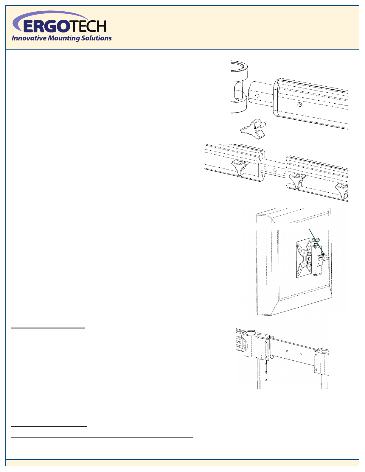
2) Once the base unit is secured, begin attaching the extrusions from
the unit outward. Place the telescoping extrusions onto the main
unit joints and secure from the backside with the knobs (as shown
in Fig.3). Next secure the non-telescoping outbound extrusions with
the knobs as before.
Fig .3
3) Note: If mounting larger sized or wide format monitors
and additional extrusion length is required, simply extend
the inner telescoping extrusions to provide the necessary
space (as shown in Fig.4). They must be extended equally
on each side of the unit to insure mounting symmetry.
ERGOTECH GROUP, INC.
8 Westchester Plaza
Elmsford, NY 10523
914-347-3800
Fig .4
4) Attach quick release pivots to back of each monitor using
Phillips head screws provided. Be sure that the silver release
button is positioned toward the top of the monitor. (as shown
in Fig.5).
Place each monitor on the mounting blocks by tipping the monitor
back approximately 45 degrees and then down until the silver release
button engages grove and clicks down into place.
Upper Tier Units Only: Slide the upper tier bars into the slots in the top
plate and guide them down into the unit guide block until they are fully
seated. This will line up the rear holes in order to place the securing
bolt later. Do not place the bolts until the center cross support plate is
in place joining the upright bars. Once the upper tier is fully assembled
place the bolts from the rear and tighten. Again starting from the center,
attach the extrusions to the upper tier as before.
Silver Release button
Fig .5
Fig .6
To adjust monitors:
Left/Right and Up/Down: Grasp monitor with both hands and adjust to desired position.
To tension the vertical adjustment to the weight of monitor: Tighten the 5mm bolt on the right side of the pivot
with the hex wrench provided.
www.ergotechgroup.com
 Loading...