

Page 1
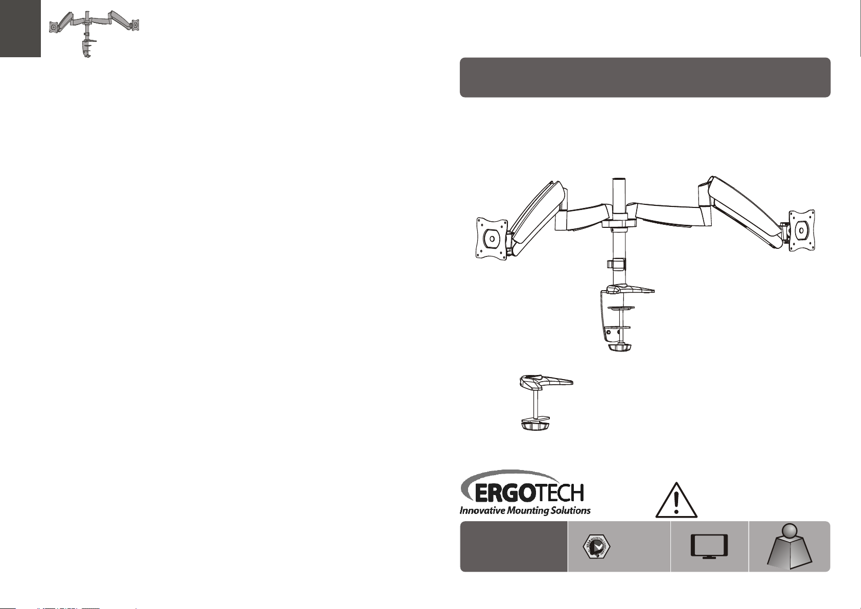
INSTALLATION INSTRUCTIONS
Counterbalance LCD Desk Mount
320 -C1 4- C02 4
75x75
100x1 00
CA UTI ON : DO NOT EXCE ED MA XIMUM
L IS TE D W EI GH T CA PAC IT Y. SE RI OU S
I NJ URY OR PR OP ER TY DA MA GE MA Y
O CC UR !
19.8lbs
24"
MAX
ISSUED: JAN. 2017
MAX
MAX
Page 2

NOTE: Rea d the entire instr uction manual be fore you st art ins tallati on and as sembly.
WARNING
• Do not begin the installation until you have read and understood the instructions
and warnings contained in this installation sheet. If you have any question
regarding any of the instruction or warning, please contact your local distributor.
• This mounting bracket was designed to be installed and utilized ONLY as
specified in this manual. Improper installation of this product may cause damage
or serious injury.
• Make sure that the supporting surface will safely support the combined load of
the equipment and all attached hardware and components.
• Always use an assistant or mechanical lifting equipment to safely lift and position
equipment.
• Tighten screws firmly, but do not over tighten. Over tightening can damage the
items, greatly reducing their holding power.
Component Checklist
IMPORTANT: Ensure t hat y ou ha ve re cei ved all par ts ac cor din g to the comp one nt ch eck list prio r to in sta lli ng. If
any p art s are m iss ing or faulty, te lep hone your l oca l dis tri butor for a r epl ace men t.
adapt er br ack et
assem bly ( x1)
A
desk cl amp
assem bly ( x1)
C
Package M x2
pole (x 1)
B
• This product is intended for indoor use only. Using this product outdoors could
lead to product failure and personal injury.
M4x14 ( x4)
M-A
Package P
6mm Allen key
P-A
P-D
(x1)
M5x14 ( x4)
M-B
4mm Allen key
base pl ate ( x1)
P-B
P-E
(x1)3mm Allen key (x1)
D5 wash er (x 4)
M-C
5mm Allen key
pad (x1 )
P-F
P-C
(x1)
21
Page 3
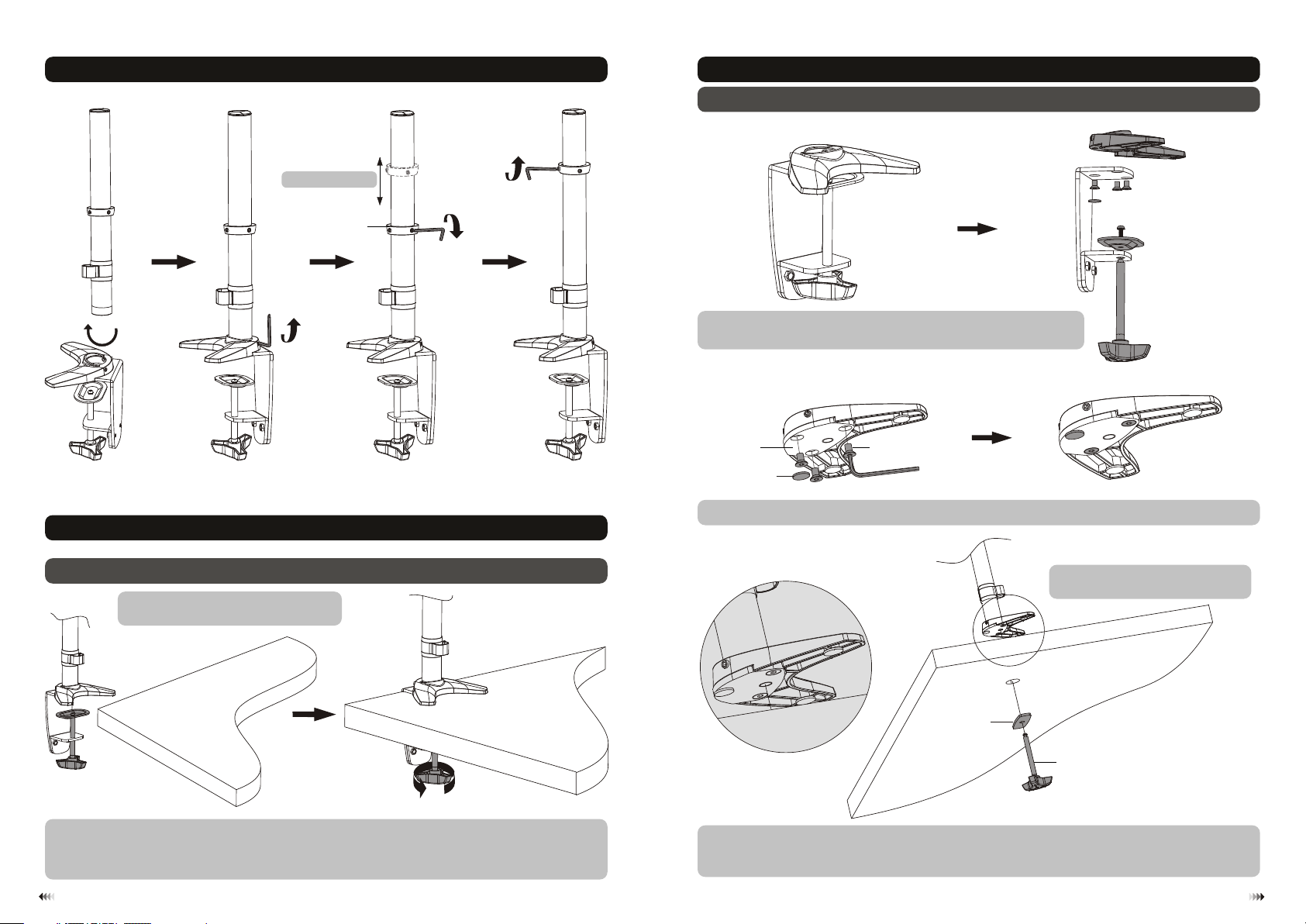
1. Install the Pole and Desk Clamp Assembly
2. Installation to Desk
2b. Hole Installation
tight en
2. Installation to Desk
2a. Edge Installation
Note: m in. d esk top t hic kness=10 mm
max. deskt op th ick nes s=90mm
adjus tab le he igh t
P-A
tight en
colla r
P-A
loose n
P-A
Disassembl e the desk clamp assembly and select the right components
for hole insta llation.
base pl ate
rubber pad
Re-install t he base plate with three retained attach screws, tighten s ecurely.
attach screw
P-B
Note: m in. h ole d iam eter =10mm
max. hole di ame ter = 70m m
tight en
• Determine ap proximate location for mount keeping in mind display siz e, height adjustment an d pitch/roll
requiremen ts.
• Slip the desk mo unt assembly over the edge of desk so that clamp fully contact s desk edge.
• Turn the knob to adj ust the clamp to edge of desk and secure it tightly.
3
pad
clamp a dju stm ent s crew
From below des k, insert retained clamp adjustment screw through pad an d up through hole in desk. Thread
screw by turni ng the knob into base plate but not tighten completely at this t ime. Center the desk mount
assembly ove r hole, securely tighten screw.
434
Page 4
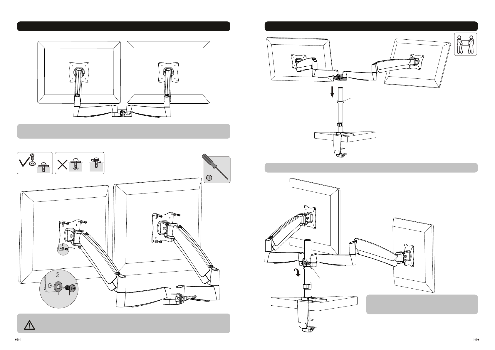
3. Install Adapter Bracket
Pick up and orie nt the adapter bracket assembly so that the mounting holes i n the assembly are aligne d with
the holes in the b ack of display.
4. Install Adapter Bracket Assembly (attached display)
collar
M-A
M-B
TV
TV
M-C
Screw t he ad apt er br acket assembl y ont o the d isp lay.
Tig hten all screws b ut do n ot ov er ti ghten.
TV
Insert the ada pter bracket assembly (attached display) into the pole t ill it touches the collar.
tight en
adjustable h andle
Pulling up on the handle disengages it from the spline and
allows it to rotate 360 degrees in either direction. Releasing
the handle re-engages the spline for tightening or adjusting.
65
Page 5
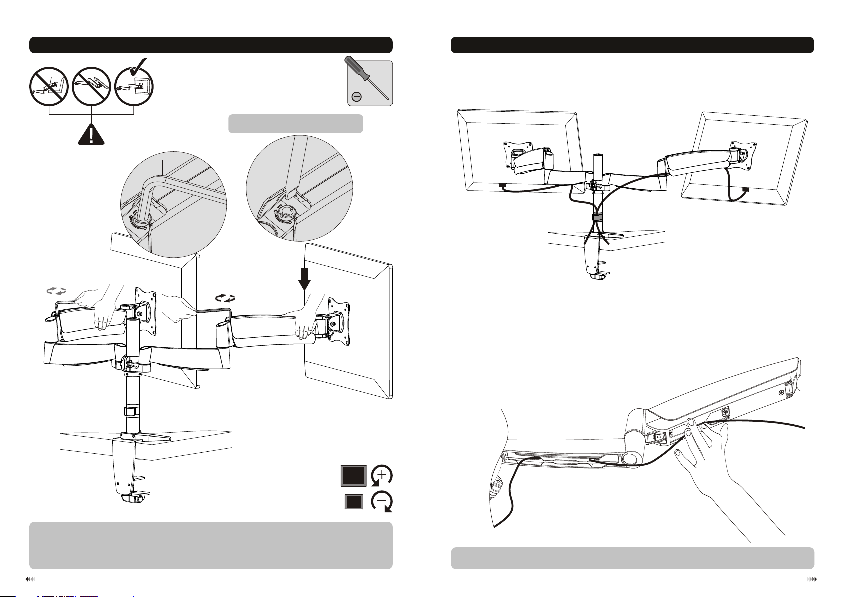
5. Height-Adjust Tension
P-D
Pleas e tig hte n soc ket set screw if th e
joint s mak e pop pin g sounds in use.
6. Cable Management
Please keep th e forearm level when to adjust pressure. Use a proper Allen key to sli ghtly loosen or tighten t he
adjustment s crew as necessary.
If display set tles on its own, rotate adjustment screw towards the "+" sym bol.
If display ris es on its own, rotate adjustment screw towards the "-" symbo l.
3
O
F LD
CHER
T
A
C
DUST
Connect the ca bles to the display, press cable cover inward to route th e cables through the spac e.
Note: Leave sl ack in cable for arm movement.
87
Page 6
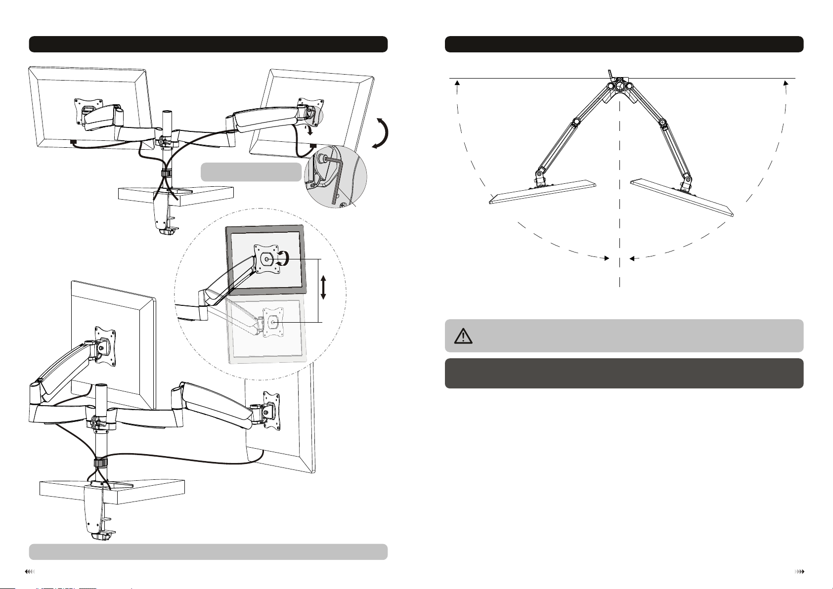
7. Adjustment
heigh t adj ust abl e
max33 5mm
36 0°36 0°36 0°
Tigh ten sc rews by usin g All en
key to fix the posit ion.
tight en
+90°
4
0-
8. Pivot Adjustment Range
edge of desk
°
A
r
m
in
s
w
gs
P-C
90°
Swing ing t he ar m bey ond t his range may res ult i n the m oun t slipping of the d esk c aus ing
serio us in jur y!
Maint ena nce
• Check t hat t he br ack et is s ecure and sa fe to u se at r egu lar intervals (at l eas t eve ry three months ).
• Pleas e con tac t you r dealer if you hav e any q ues tio ns.
r
A m
gs
win
s
90°
Adjus t to th e des ire d location or til t.
9
10
 Loading...