

Page 1

Rev.6 EM19XR4170F
6-Axis Robots
VT series
MANIPULATOR MANUAL
Page 2

MANIPULATOR MANUAL
VT series Rev.6
Page 3

6-Axis ROBOT
VT series Manipulator Manual
Rev. 6
Copyright 2018-2019 SEIKO EPSON CORPORATION. All rights reserved.
VT Rev.6 i
Page 4

1.
Damage or malfunction caused by improper use which is not described in the
manual, or careless use.
2.
Malfunctions caused by customers
3.
Damage due to improper adjustments or unauthorized repair attempts.
4.
Damage caused by natural disasters such as earthquake, flood, etc.
1.
If the Manipulator or associated equipment is used outside of the usage conditions
and product specifications described in the manuals, this warranty is void.
2.
If you do not follow the WARNINGS and CAUTIONS in this manual, we cannot be
responsible for any malfunction or accident, even if the result
3.
We cannot foresee all possible dangers and consequences. Therefore, this manual
cannot warn the user of all possible hazards.
FOREWORD
Thank you for purchasing our robot products.
This manual contains the information necessary for the correct use of the manipulator.
Please carefully read this manual and other related manuals before installing the robot
system.
Keep this manual handy for easy access at all times.
WARRANTY
The Manipulator and its optional parts are shipped to our customers only after being
subjected to the strictest quality controls, tests, and inspections to certify its compliance
with our high performance standards.
Product malfunctions resulting from normal handling or operation will be repaired free of
charge during the normal warranty period. (Please contact the supplier of your region for
warranty period information.)
However, customers will be charged for repairs in the following cases (even if they occur
during the warranty period):
Warnings, Cautions, Usage:
’ unauthorized disassembly.
is injury or death.
ii VT Rev.6
Page 5

TRADEMARKS
Microsoft, Windows, and Windows logo are either registered trademarks or trademarks of
Microsoft Corporation in the United States and/or other countries. Other brand and
product names are trademarks or registered trademarks of the respective holders.
NOTICE
No part of this manual may be copied or reproduced without authorization.
The contents of this manual are subject to change without notice.
Please notify us if you should find any errors in this manual or if you have any comments
regarding its contents.
MANUFACTURER
CONTACT INFORMATION
Contact information is described in “SUPPLIERS” in the first pages of the following
manual:
Robot System Safety and Installation Read this manual first
VT Rev.6 iii
Page 6

Regarding battery disposal
The crossed out wheeled bin label that can be found on your product indicates that this
product and incorporated batteries should not be disposed of via the normal household
waste stream. To prevent possible harm to the environment or human health please
separate this product and its batteries from other waste streams to ensure that it can be
recycled in an environmentally sound manner. For more details on available collection
facilities please contact your local government office or the retailer where you purchased
this product. Use of the chemical symbols Pb, Cd or Hg indicates if these metals are used
in the battery.
This information only applies to customers in the European Union, according to
DIRECTIVE 2006/66/EC OF THE EUROPEAN PARLIAMENT AND OF THE
COUNCIL OF 6 September 2006 on batteries and accumulators and waste batteries and
accumulators and repealing Directive 91/157/EEC and legislation transposing and
implementing it into the various national legal systems.
For other countries, please contact your local government to investigate the possibility of
recycling your product.
The battery removal/replacement procedure is described in the following manuals:
VT series manipulator manual
Maintenance: 18.4 Replacing the Lithium Battery
iv VT Rev.6
Page 7

Controller Firmware
Before Ver. 7.4.6
!!!
Ver.7.4.7 or later
OK
EPSON
RC+
Before Reading This Manual
This section describes what you should know before reading this manual.
Structure of Robot System
The VT series Manipulators can be used with the following combinations of software.
VT6-A901S, VT6-A901C, VT6-A901P
EPSON RC+ 7.0
OK: Compatible All functions of the EPSON RC+ 7.0 and the robot system are
!!!: Compatible Connection is OK. It is recommended to use the following version
Shape of Motors
The shape of the motors used for the Manipulator that you are using may be different from
the shape of the motors described in this manual because of the specifications.
Setting by Using Software
This manual contains setting procedures by using software. They are marked with the
following icon.
Ver.7.4.56.2 or later
available.
or later. Display or control may not be operated properly.
EPSON RC+ 7.0 Ver.7.4.7
VT Rev.6 v
Page 8

vi VT Rev.6
Page 9

Setup & Operation
1. Safety 3
1.1 Conventions ......................................................................................... 3
1.2 Design and Installation Safety ............................................................. 4
1.3 Operation Safety.................................................................................. 5
1.4 Emergency Stop .................................................................................. 7
1.5 How to Move Arms with the Electromagnetic Brake ........................... 9
1.6 Precaution for Operation in Low Power Status ................................. 10
1.7 Labels ................................................................................................ 11
2. Specifications 13
2.1 Features of VT series Manipulators .................................................. 13
2.2 Model Number ................................................................................... 13
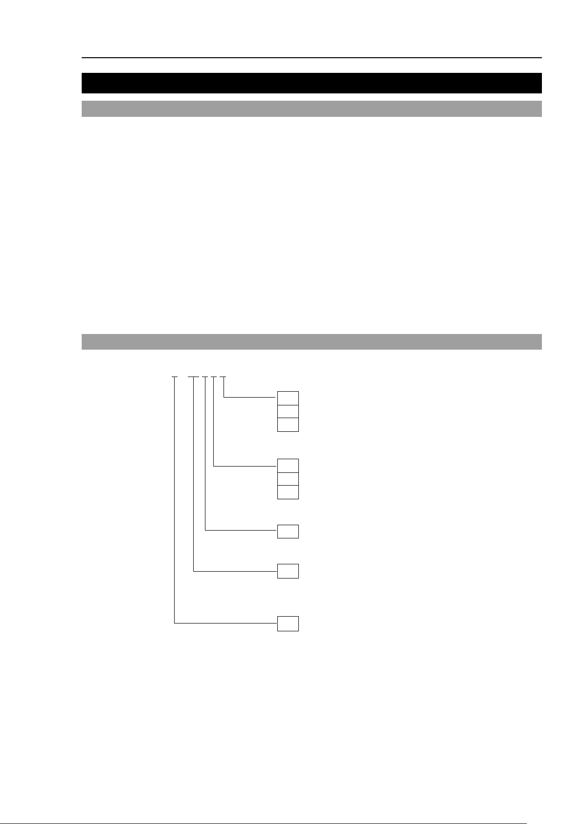
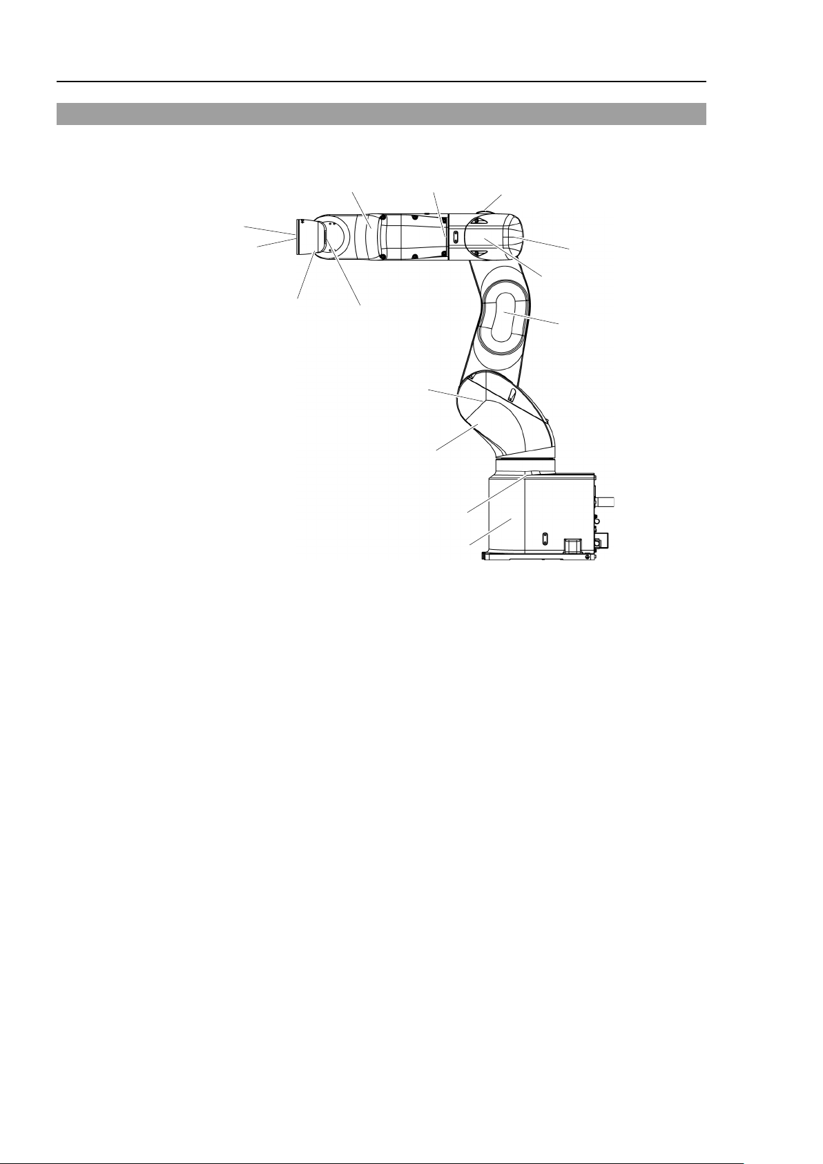
2.3 Part Names ........................................................................................ 14
2.4 Outer Dimensions .............................................................................. 16
2.5 Standard Motion Range .................................................................... 18
2.6 System Example................................................................................ 20
2.7 Specifications .................................................................................... 21
2.8 How to Set the Model ........................................................................ 25
TABLE OF CONTENTS
1.5.1 Arm Motions ............................................................................. 9
1.5.2 Release the Brake by the Software ....................................... 10
3. Environments and Installation 26
3.1 Environmental Conditions ................................................................. 26
3.2 Base Table ........................................................................................ 27
3.3 Mounting Dimensions ........................................................................ 29
3.4 Unpacking and Transportation .......................................................... 30
3.5 Installation Procedure ........................................................................ 31
3.6 Power Supply .................................................................................... 32
3.6.1 Specifications......................................................................... 32
3.6.2 AC Power Cable .................................................................... 33
3.6.3 Breaker .................................................................................. 34
3.6.4 Grounding .............................................................................. 34
3.7 Connecting the Cables ...................................................................... 35
3.7.1 Connection Example ............................................................. 35
3.7.2 Noise Countermeasures ........................................................ 38
3.8 Relocation and Storage ..................................................................... 39
3.8.1 Precautions for Relocation and Storage ............................... 39
3.8.2 Relocation .............................................................................. 40
3.9 Checking the Basic Orientation ......................................................... 42
3.10 Origin Position Label ....................................................................... 42
VT Rev.6 vii
Page 10

TABLE OF CONTENTS
4. Setting of End Effectors 43
5. Motion Range 55
4.1 Attaching an End Effector .................................................................. 43
4.2 Attaching Cameras and Air Valves .................................................... 44
4.3 Weight and Inertia Settings ................................................................ 44
4.3.1 Weight Setting ........................................................................ 47
4.3.2 INERTIA Setting ..................................................................... 50
4.4 Precautions for Auto Acceleration/Deceleration of Joint #3 .............. 54
5.1 Motion Range Setting by Pulse Range (for All Joints)....................... 55
5.1.1 Max. Pulse Range of Joint #1 ................................................ 56
5.1.2 Max. Pulse Range of Joint #2 ................................................ 56
5.1.3 Max. Pulse Range of Joint #3 ................................................ 57
5.1.4 Max. Pulse Range of Joint #4 ................................................ 57
5.1.5 Max. Pulse Range of Joint #5 ................................................ 57
5.1.6 Max. Pulse Range of Joint #6 ................................................ 58
5.2 Motion Range Setting by Mechanical Stops ...................................... 59
5.2.1 Motion Range Setting of Joint #1 ........................................... 59
5.2.2 Motion Range Setting of Joint #2 ........................................... 60
5.2.3 Motion Range Setting of Joint #3 ........................................... 61
5.3 Restriction of Manipulator Operation by Joint Angle Combination .... 62
5.4 Coordinate System ............................................................................. 63
5.5 Changing the Robot ........................................................................... 64
5.6 Setting the Cartesian (Rectangular) Range in the XY Coordinate
System of the Manipulator ................................................................. 65
6. Operation Mode & LED 66
6.1 Overview ............................................................................................ 66
6.2 Switch Operation Mode ...................................................................... 66
6.3 Program Mode (AUTO) ...................................................................... 67
6.3.1 What is Program Mode (AUTO)? ........................................... 67
6.3.2 Setup from EPSON RC+ 7.0 .................................................. 67
6.4 Auto Mode (AUTO) ............................................................................ 68
6.4.1 What is Auto mode (AUTO)? ................................................. 68
6.4.2 Setup from EPSON RC+ 7.0 .................................................. 68
6.4.3 Setup from Control Device ..................................................... 69
6.5 LED ..................................................................................................... 70
7. Development PC Connection Port 71
7.1 What is Development PC Connection Port ........................................ 71
7.2 Precaution .......................................................................................... 72
7.3 Software Setup and Connection Check ............................................. 72
7.4 Disconnection of Development PC and Manipulator ......................... 73
viii VT Rev.6
Page 11

TABLE OF CONTENTS
8. Memory Port 74
8.1 What is Controller Status Storage Function? .................................... 74
8.2 Before Using Controller Status Storage Function ............................. 74
8.2.1 Precautions ............................................................................ 74
8.2.2 Adoptable USB Memory ........................................................ 75
8.3 Controller Status Storage Function ................................................... 75
8.3.1 Controller Status Storage ...................................................... 75
8.3.2 Load Data with EPSON RC+ 7.0 .......................................... 76
8.3.3 Transfer with E-mail ............................................................... 77
8.4 Details of Data ................................................................................... 78
9. LAN (Ethernet Communication) Port 79
9.1 What is the LAN (Ethernet Communication) Port ............................. 79
9.2 IP Address ......................................................................................... 80
9.3 Changing Manipulator IP Address .................................................... 80
9.4 Connection of Development PC and Manipulator with Ethernet ...... 81
9.5 Disconnection of Development PC and Manipulator with Ethernet .. 83
10. TP Port 84
10.1 What is the TP Port? ....................................................................... 84
10.2 Teach Pendant Connection ............................................................. 84
11. Options 85
11.1 Camera Plate Unit ........................................................................... 85
11.2 Tool Adapter (ISO flange) ............................................................... 87
11.3 Adjustable Mechanical Stops .......................................................... 88
11.4 External Wiring Kit ........................................................................... 88
12. EMERGENCY 95
12.1 Safeguard Switch and Latch Release Switch ................................. 95
12.1.1 Safeguard Switch ................................................................ 96
12.1.2 Latch Release Switch .......................................................... 97
12.1.3 Checking Latch Release Switch Operation ......................... 97
12.2 Emergency Stop Switch Connection ............................................... 98
12.2.1 Emergency Stop Switch ...................................................... 98
12.2.2 Checking Emergency Stop Switch Operation ..................... 98
12.2.3 Recovery from Emergency Stop ......................................... 98
12.3 Pin Assignments .............................................................................. 99
12.4 Circuit Diagrams ............................................................................ 100
12.4.1 Example 1: External emergency stop switch typical application
......................................................................................................... 100
12.4.2 Example 2: External safety relay typical application ......... 101
VT Rev.6 ix
Page 12

TABLE OF CONTENTS
13. Standard I/O Connector 102
14. I/O Remote Settings 114
13.1 Standard, Cleanroom Model .......................................................... 102
13.1.1 Input Circuit (Standard, Cleanroom Model) ....................... 102
13.1.2 Output Circuit (Standard, Cleanroom Model) .................... 105
13.2 Protection Model ............................................................................ 108
13.2.1 Input Circuit (Protection Model) ......................................... 108
13.2.2 Output Circuit (Protection Model) ....................................... 110
13.2.3 Pin Assignments of Input and Output Circuit
(Protection Model) ............................................................. 112
13.3 I/O Cable Product Procedure ......................................................... 113
13.3.1 I/O Cable Connecting Method ............................................ 113
13.3.2 How to Fix the I/O Cable .................................................... 113
14.1 I/O Signal Description .................................................................... 115
14.1.1 Remote Input Signals ......................................................... 115
14.1.2 Remote Output Signals ...................................................... 119
14.2 Timing Specifications ..................................................................... 122
14.2.1 Precautions for Remote Input Signals ............................... 122
14.2.2 Timing Diagram for Operation Execution Sequence ......... 122
14.2.3 Timing Diagram for Program Execution Sequence ........... 122
14.2.4 Timing Diagram for Safety Door Input Sequence .............. 123
14.2.5 Timing Diagram for Emergency Stop Sequence ............... 123
15. SD Card Slot 124
16. RESET Switch 125
17. Fieldbus I/O 126
x VT Rev.6
Page 13

Maintenance
TABLE OF CONTENTS
1. Safety Maintenance 131
2. General Maintenance 132
2.1 Maintenance Inspection .................................................................. 132
2.1.1 Schedule for Maintenance Inspection ................................. 132
2.1.2 Inspection Point ................................................................... 133
2.2 Overhaul (Parts Replacement) ........................................................ 134
2.3 Tightening Hexagon Socket Head Cap Bolts.................................. 136
2.4 Matching Origins.............................................................................. 136
2.5 Layout of Maintenance Parts .......................................................... 137
3. Manipulator Structure 138
4. Alarm 140
4.1 Maintenance .................................................................................... 141
4.2 Maintenance Information ................................................................. 142
4.2.1 How to Check the Maintenance Information ....................... 142
4.2.2 How to Edit the Maintenance Information ........................... 143
4.2.3 Alarm Notifying Method ....................................................... 144
4.2.4 How to Cancel the Alarm ..................................................... 144
5. Backup and Restore 145
5.1 What is the Backup Controller Function .......................................... 145
5.2 Backup Data Types ......................................................................... 145
5.3 Backup ............................................................................................. 146
5.4 Restore ............................................................................................ 147
6. Firmware Update 150
6.1 Updating Firmware .......................................................................... 150
6.2 Firmware Upgrade Procedure ......................................................... 150
6.3 Manipulator Recovery ..................................................................... 152
6.4 Firmware Initialization Procedure .................................................... 153
7. Covers 155
7.1 Arm #1 Cover .................................................................................. 156
7.2 Arm #2 Cover .................................................................................. 158
7.3 Arm #3 Cover .................................................................................. 159
7.4 Arm #4 Cover 1 ............................................................................... 160
7.5 Arm #4 Cover 2 ............................................................................... 161
VT Rev.6 xi
Page 14

TABLE OF CONTENTS
8. Cable 166
9. Joint #1 184
10. Joint #2 195
7.6 Power Cable Cover .......................................................................... 163
7.7 Connector Plate ............................................................................... 164
8.1 Replacing Cable Unit ....................................................................... 167
8.2 Insert or Pull out of Power Cable ..................................................... 183
9.1 Replacing Joint #1 Motor ................................................................. 185
9.2 Replacing Joint #1 Reduction Gear Unit .......................................... 189
9.3 Replacing Joint #1 Timing Belt ........................................................ 190
10.1 Replacing Joint #2 Motor ............................................................... 196
10.2 Replacing Joint #2 Reduction Gear Unit ........................................ 202
10.3 Replacing Joint #2 Timing Belt ...................................................... 203
11. Joint #3 204
11.1 Replacing Joint #3 Motor ............................................................... 205
11.2 Replacing Joint #3 Reduction Gear Unit ........................................ 211
11.3 Replacing Joint #3 Timing Belt ...................................................... 212
12. Joint #4 213
12.1 Replacing Joint #4 Motor ............................................................... 214
12.2 Replacing Joint #4 Reduction Gear Unit ........................................ 219
12.3 Replacing Joint #4 Timing Belt ...................................................... 220
13. Joint #5 224
13.1 Replacing Joint #5 Motor ............................................................... 225
13.2 Replacing Joint #5 Reduction Gear Unit ........................................ 229
13.3 Replacing Joint #5 Timing Belt ...................................................... 230
14. Joint #6 231
14.1 Replacing Joint #6 Motor ............................................................... 232
14.2 Replacing Joint #6 Reduction Gear Unit ........................................ 236
14.3 Replacing Joint #6 Timing Belt ...................................................... 237
15. AMP Board 238
15.1 Replacing AMP Board on Joint #1, #2, and #3 .............................. 240
15.2 Replacing AMP Board on Joint #4 ................................................. 242
15.3 Replacing AMP Board on Joint #5 and #6 ..................................... 243
xii VT Rev.6
Page 15

TABLE OF CONTENTS
16. LED Plate 244
16.1 Replacing LED Plate ..................................................................... 245
17. Felt Sheet 246
17.1 Replacing Joint #2 Felt Sheet ....................................................... 247
17.2 Replacing Joint #3 Felt Sheet ....................................................... 248
18. Controller Unit 249
18.1 Replacing Controller Unit .............................................................. 250
18.1.1 Standard, Cleanroom Model ............................................. 251
18.1.2 Protection Model ................................................................ 254
18.2 Replacing Power Board ................................................................. 258
18.3 Replacing CPU/DPB Board ........................................................... 259
18.4 Replacing Lithium Battery ............................................................. 261
18.5 Replacing Cooling Fan .................................................................. 261
18.6 Replacing SD Card ........................................................................ 262
18.6.1 Standard, Cleanroom Model ............................................. 262
18.6.2 Protection Model ................................................................ 263
19. Calibration 264
19.1 Overview ........................................................................................ 264
19.2 Calibration Procedures .................................................................. 267
20. Restrictions 271
20.1 Commands Cannot Use ................................................................ 271
20.2 Commands Cause Motion Error If Specifying RS-232C ............... 271
20.3 Commands Cause Error ................................................................ 272
20.4 Restrictions of Functions ............................................................... 274
20.3.1 Conveyor Tracking Commands ......................................... 272
20.3.2 PG Commands .................................................................. 273
20.3.3 R-I/O Commands ............................................................... 273
20.3.4 Force Sensing Commands ................................................ 273
20.3.5 Other (FineDist) ................................................................. 273
20.3.6 Other (HealthCalcPeriod) .................................................. 273
20.3.7 Other (ChDisk) ................................................................... 273
20.4.1 TP3 .................................................................................... 274
20.4.2 Loop Processing ................................................................ 274
20.4.3 Camera Searching by CV1/CV2........................................ 275
20.4.4 Restore the Data of Backup Controller Function .............. 275
VT Rev.6 xiii
Page 16

TABLE OF CONTENTS
21. Error Code Table 276
22. Maintenance Parts List 277
Appendix A: Open Source Software License 279
xiv VT Rev.6
Page 17

Setup & Operation
This volume contains information for setup and operation of the
VT
Please read this volume
operating the Manipulators.
series Manipulators.
thoroughly before setting up and
Page 18

Page 19
1. Safety
ted instructions are not followed
death caused by electric shock exists if the associated
or physical damage to equipment and facilities exists if the
Installation and transportation of Manipulators and robotic equipment shall be performed
by qualified personnel and should conform to all national and local codes. Please read this
manual and other related manuals before installing the robot system or before connecting
cables.
Keep this manual handy for easy access at all times.
1.1 Conventions
Important safety considerations are indicated throughout the manual by the following
symbols. Be sure to read the descriptions shown with each symbol.
WARNING
WARNING
Setup & Operation 1. Safety
This symbol indicates that a danger of possible serious injury or
death exists if the associa
properly.
This symbol indicates that a danger of possible serious injury or
instructions are not followed properly.
CAUTION
This symbol indicates that a danger of possible harm to people
associated instructions are not followed properly.
VT Re v. 6 3
Page 20
Setup & Operation 1. Safety
Personnel who design and/or construct the robot system with this product must
read the
requirements before designing and/or constructing the robot system. Designing
and/or constructing the robot system without understanding the safety
requirements is extremely hazardous, may result in serious bodily injury and/or
sever
problems.
The robot
their respective manuals.
strictly for use in a normal indoor environment.
environment that exceeds the specified enviro
shorten the life cycle of the product but may also cause serious safety problems.
The robot system must be used within the installation requirements described in
the manuals.
may not only shorten the life cycle of the product but also cause serious safety
problems.
1.2 Design and Installation Safety
Only trained personnel should design and install the robot system. Trained personnel are
defined as those who have taken robot system training and maintenance training classes held
by the manufacturer, dealer, or local representative company, or those who understand the
manuals thoroughly and have the same knowledge and skill level as those who have
completed the training courses.
To ensure safety, a safeguard must be installed for the robot system. For details on the
safeguard, refer to the Installation and Design Precautions in the Safety chapter of the
EPSON RC+ User’s Guide.
The following items are safety precautions for design personnel:
■
Safety chapter in the EPSON RC+ User’s Guide to understand the safety
e equipment damage to the robot system, and may cause serious safety
■
system must be used within the environmental conditions described in
WARNING
■
Further precautions for installation are mentioned in Setup & Operation: 3. Environments
and Installation. Please read this chapter carefully to understand safe installation
procedures before installing the robots and robotic equipment.
This product has been designed and manufactured
Using the product in an
nmental conditions may not only
Using the robot system outside of the installation requirements
4 VT Rev.6
Page 21
1.3 Operation Safety
Please carefully read the
of the
before operating the robot system.
Operating the robot system without understanding the safety requirements is
extremely hazardous and may result in serious bodily injury and/or sever
equipment damage to the robot system.
■
Do not enter the operating
system is turned ON.
hazardous and may cause serious safety problems as the Manipulator may move
even if it seems to be stopped.
■
Before operating the robot system, make sure that no one is inside the
safeguarded area.
even when someone is inside the safeguarded area.
The motion of the Manipulator is always in restricted (low
status to secure the safety of an operator.
while someone is inside the safeguarded area is extremely hazardous and may
result in serious safety problems in case that the Manipulator moves unexpect
■
Immediately press the Emergency Stop switch whenever the Manipulator moves
abnormally while the robot system is operated.
the Manipulator moves abnormally is extremely hazardous and may result in
serious bodily i
To shut off power
source. Be sure to connect the AC power cable to a power receptacle.
DO NOT connect it directly to a factory power source.
■
Before
related equipment,
Performing any replacement procedure with the power ON is extremely hazardous
and may result in
■
Do not connec
system is turned ON. Connecting or disconnecting the motor connectors
the power ON is extremely hazardous and may result
the Manipulator may move abnormally
and/or malfunction of the robot system.
The following items are safety precautions for qualified Operator personnel:
Setup & Operation 1. Safety
WARNING
■
1.3 Safety-related Requirements in the Safety chapter
Safety and Installation manual
e
area of the Manipulator while the power to the robot
Entering the operating area with the power ON is extremely
The robot system can be operated in the mode for teaching
speed and low power)
However, operating the robot system
edl y.
Continuing the operation while
njury and/or severe equipment damage to the robot system.
■
performing any replacement procedure, turn OFF the robot system and
WARNING
to the robot system, disconnect the power plug from the power
and then disconnect the power plug from the power source.
electric shock and/or malfunction of the robot system.
t or disconnect the motor connectors while the power to the robot
with
in serious bodily injury as
, and also may result in electric shock
VT Re v. 6 5
Page 22

Setup & Operation 1. Safety
Whenever possible, only one person should operate the robot system.
necessary to operate the robot system with more than one person, ensure that all
people involved communicate with each other as to what they are doing and take
all necessary safety precautions.
Each
If the joints are operated
the
with grease during movement.
larger than
Vibration
robot motion
natural
measures.
Manipulator
■
If it is
CAUTION
■
■
■
Joint:
Manipulator may get damaged early due to the bearings are not being covered
30 degrees for about five to ten times a day.
(resonance) may occur continuously depending on the combination of
vibration frequency of the Arm and can be controlled by following
Changing Manipulator speed
Changing the teach points
Changing the end effector load
until temperature falls. After confirming that the temperature of the Manipulator
falls and is not hot when you touch it. Then perform teaching or maintenance.
repeatedly with the operating angle less than 5 degrees,
To prevent early breakdown, move the joints
speed, Arm orientation, and end effector load. Vibration arises from
may be heated due to motor heat etc. Do not touch the Manipulator
6 VT Rev.6
Page 23

1.4 Emergency Stop
If the Manipulator moves abnormally during operation, immediately press the Emergency
Stop switch. Pressing the Emergency Stop switch immediately changes the Manipulator
to deceleration motion and stops it at the maximum deceleration speed.
However, avoid pressing the Emergency Stop switch unnecessarily while the Manipulator
is running normally. Pressing the Emergency Stop switch locks the brake and it may cause
wear on the friction plate of the brake, resulting in the short life of the brake.
Normal brake life cycle: About 2 years (when the brakes are used 100 times/day)
To place the system in emergency mode during normal operation, press the Emergency Stop
switch when the Manipulator is not moving.
Refer to the Setup & Operation: 12. EMERGENCY for instructions on how to wire the
Emergency Stop switch circuit.
Do not turn OFF the power while the Manipulator is operating.
If you attempt to stop the Manipulator in emergency situations such as “Safeguard Open”,
make sure to stop the Manipulator using the Emergency Stop switch.
If the Manipulator is stopped by turning OFF the power while it is operating, following
problems may occur.
Reduction of the life and damage of the reduction gear unit
Position gap at the joints
In addition, if the Manipulator was forced to be turned OFF by blackouts and the like while
the Manipulator is operating, make sure to check the following points after power restoration.
Whether or not the reduction gear is damaged
Whether or not the joints are in their proper positions
If there is a position gap, perform calibration by referring to the Maintenance 19.
Calibration in this manual. Also, the same troubles may occur if an error occurs and the
Manipulator stops in emergency during the operation. Check the Manipulator condition
and perform calibration if necessary.
Before using the Emergency Stop switch, be aware of the following.
- The Emergency Stop (E-STOP) switch should be used to stop the Manipulator only in
case of emergencies.
- To stop the Manipulator operating the program except in emergency, use Pause (halt)
or STOP (program stop) commands
Pause and STOP commands do not turn OFF the motors. Therefore, the brake does
not function.
- For the Safeguard system, do not use the circuit for E-STOP.
For details of the Safeguard system, refer to the following manuals.
Setup & Operation 1. Safety
EPSON RC+ User’s Guide
2. Safety - Installation and Design Precautions - Safeguard System
Safety and Installation
2.5 Connection to EMERGENCY Connector
VT Re v. 6 7
Page 24
Setup & Operation 1. Safety
VT series
ACCEL Setting
100
SPEED Setting
100
Load [kg]
6
WEIGHT Setting
6
VT6-A901**
Arm #1
0.2
Arm #2
0.3
Arm #3
0.2
Arm #4
0.2
Arm #5
0.2
Arm #6
0.2
Table Top
Ceiling
Wall
30
Arm #2
70
Arm #3
20
Arm #4
20
Arm #5
20
Arm #6
30
To check brake problems, refer to the following manuals.
Manipulator Manual Maintenance
2.1.2 Inspection Point - Inspection While the Power is ON
Safety and Installation
5.1.1 Manipulator
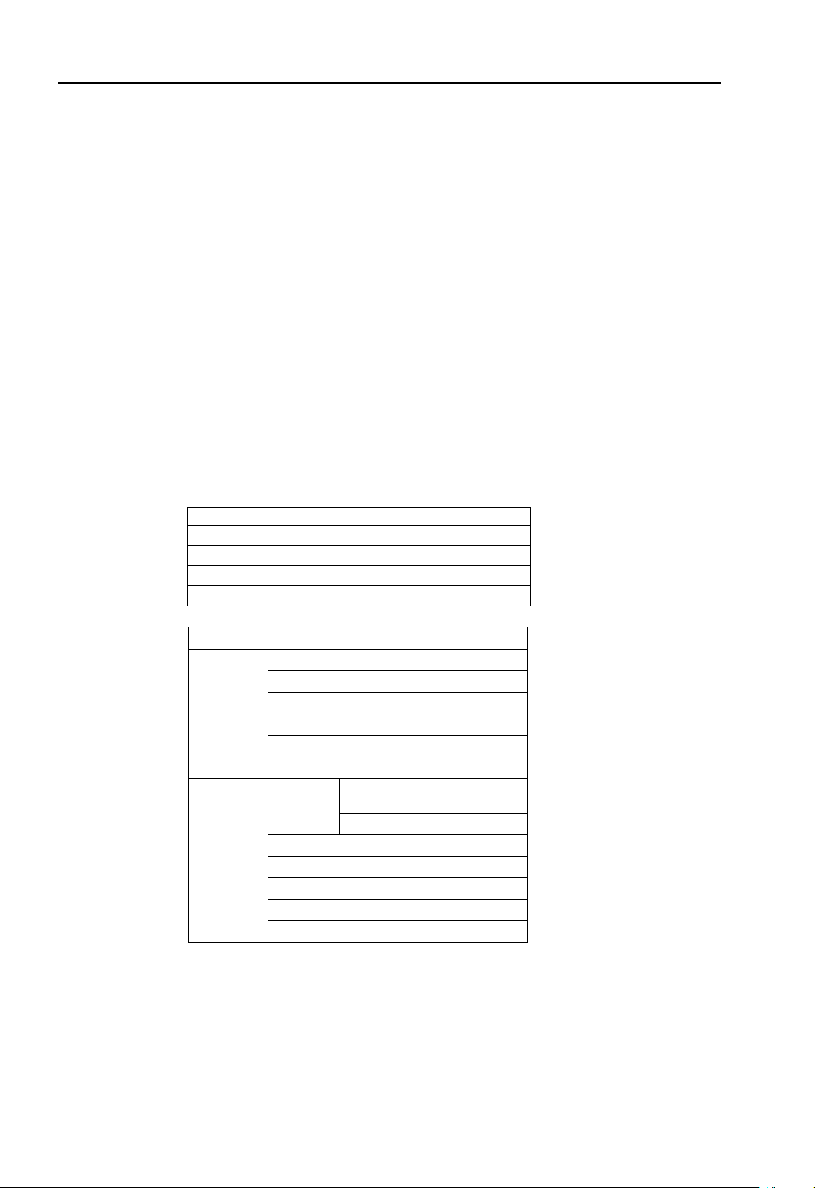
Free running distance in emergency
The operating Manipulator cannot stop immediately after the Emergency Stop switch is
pressed.
The free running time/angle/distance of the Manipulator are shown below. However,
remember that the values vary depending on following conditions.
Weight of the end effector Weight setting
Weight of workpiece Speed setting
Operating pose Accel setting
(Manipulator is operating)
- Inspection While the Power is ON (Manipulator is operating)
Conditions for measurement
Free
running
time
[sec.]
Arm #1
Free
running
angle
[°]
50
8 VT Rev.6
Page 25
Setup & Operation 1. Safety
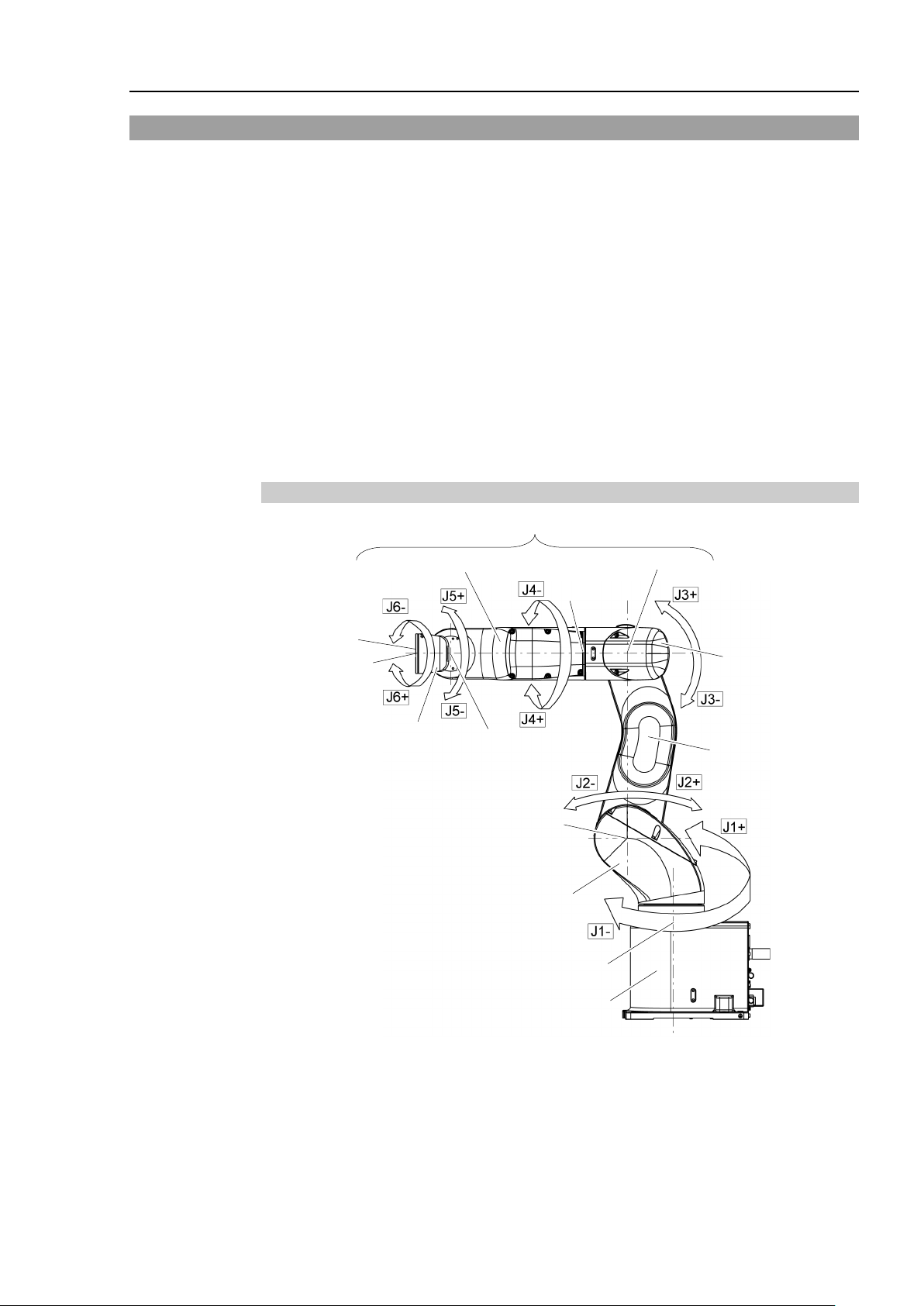
Joint #1
Base
Arm #1
(Lower Arm)
Arm #2
Arm #4
Joint #6
Joint #3
Joint #4
Joint #5
Arm #6
Joint #2
Arm #5
Arm #3
Upper Arm (Arms #3 to #6)
Joint Motion
Joint #1 : The whole Manipulator revolves.
Joint #2 : The lower arm swings.
Joint #3 : The upper arm swings.
Joint #4 : The wrist revolves.
Joint #5 : The wrist swings.
Joint #6 : The hand rotates.
1.5 How to Move Arms with the Electromagnetic Brake
When the electromagnetic brake is operating such as an emergency status, all arms cannot
be moved.
For procedures to release the electromagnetic brake, refer to the following section.
When the electromagnetic brake is released, the arms can be moved by hand.
1.5.2 Release the Brake by the Software
(When the software is available)
In an emergency situation such as you cannot /do not want to turn ON the power, you can
forcibly move the robot arm by pushing or pulling it with strong force.
A measure of force: 500N (near Arm #6)
However, if moving the robot forcibly, the joints may get damage. Be sure to do this only
in an emergency situation.
1.5.1 Arm Motions
VT Re v. 6 9
Page 26
Setup & Operation 1. Safety
Normally, release the brake of joints one by
release the brakes of two or more joints simultaneously. Releasing the brakes
of two or more joints simultaneously may cause hands and fingers to be caught
and/or equipment damage or malfunction of the Manipulator as t
Manipulator may move in unexpected directions.
Be careful of the arm falling when releasing the brake.
While the brake is being released, the Manipulator
The arm falling may cause hands and fingers to be caught and/or may cause
equipment damage or malfunction of the Manipulator.
Before releasing the brake, be sure to
EPSON
RC+
After releasing the Emergency Stop switch,
[Command Window]
>Reset
>Brake Off,
Execute the following command to turn
>Brake On,
Carefully operate the Manipulator in the low power status. A comparatively high
joint torque may be generated. It may cause your hands and fingers caught
and/or cause equipment damage or
collide with peripheral equipment.
1.5.2 Release the Brake by the Software
CAUTION
(When the software is available)
■
■
■
that you can immediately press the Emergency Stop switch. Otherwise, you
cannot immediately stop the arm falling due to an erroneous operation. The arm
falling may cause equipment damage and/or malfunction of the Manipulator.
.
[the Arm (#1 to #6) whose brake will be turned OFF]
one. Take extra care if you need to
he arms of the
’s arm falls by its own weight.
keep the Emergency Stop switch handy so
execute the following command in
ON the brake again.
[the Arm (#1 to #6) whose brake will be turned ON]
1.6 Precaution for Operation in Low Power Status
In the low power status, the Manipulator operates at low speed and low torque.
If in close proximity to the Manipulator, operate the Manipulator carefully. Otherwise,
your hands or fingers may get caught during operation. The Manipulator may also collide
with peripheral equipment and cause equipment damage or malfunction of the Manipulator.
Maximum Joint Torque in Low Power Status [Unit: N·m]
VT6-A901* (Table top mounting), VT6-A901SR (Ceiling mounting)
Joint #1 #2 #3 #4 #5 #6
Joint Torque 100.57 274.29 94.22 31.83 31.53 31.92
VT6-A901SW (Wall mounting)
Joint #1 #2 #3 #4 #5 #6
Joint Torque 210.29 274.29 94.22 31.83 31.53 31.92
■
CAUTION
10 VT Rev.6
malfunction of the Manipulator as it may
Page 27
Setup & Operation 1. Safety
and secure it tightly with a band to prevent hands or
Manipulator and
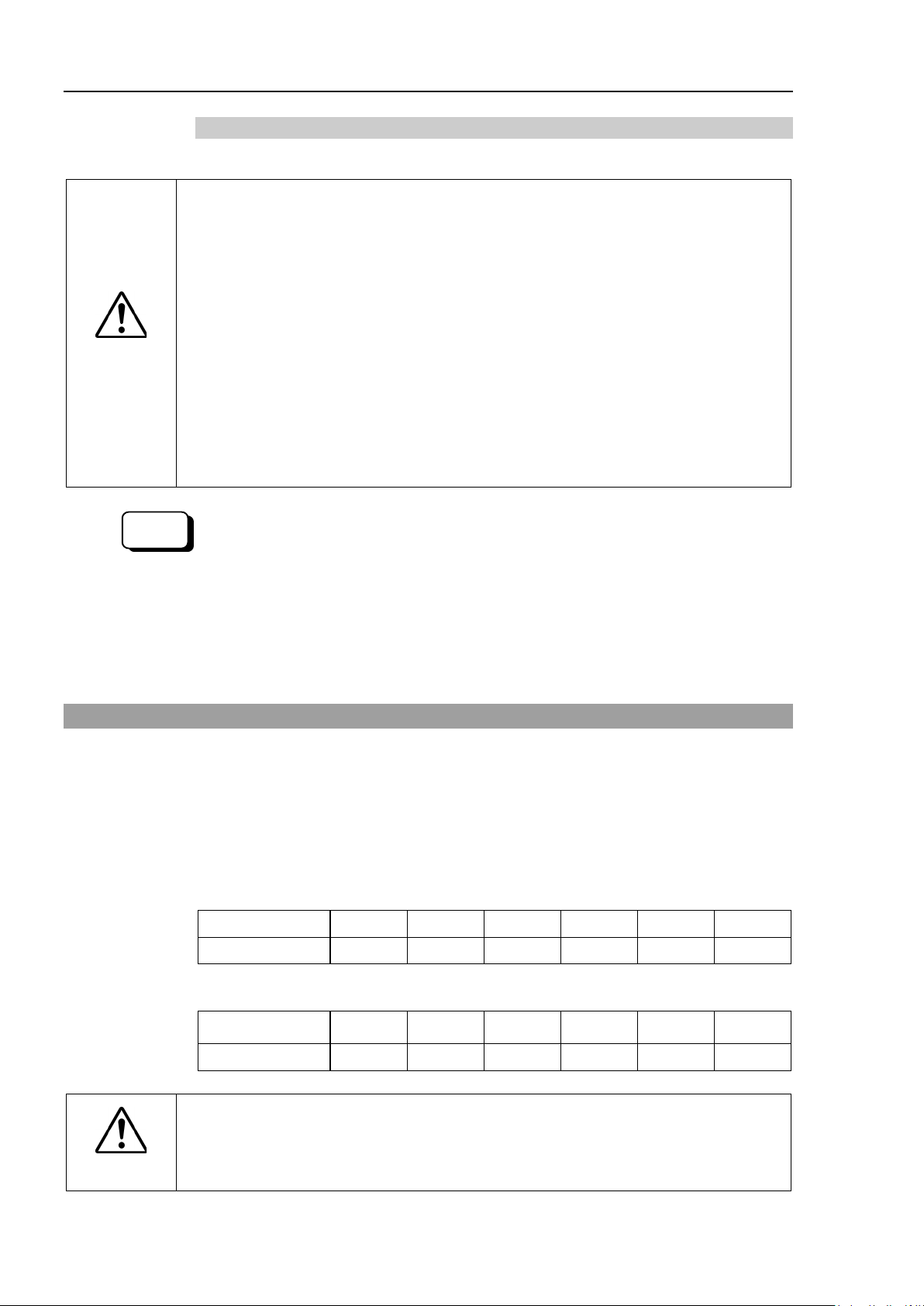
1.7 Labels
The Manipulator has the following warning labels.
The warning labels are attached around the locations where specific dangers exist.
Be sure to comply with descriptions and warnings on the labels to operate and maintain the
Manipulator safely.
Do not tear, damage, or remove the warning labels. Use meticulous care when handling
those parts or units to which the following warning labels are attached as well as the nearby
areas.
Location Warning Label NOTE
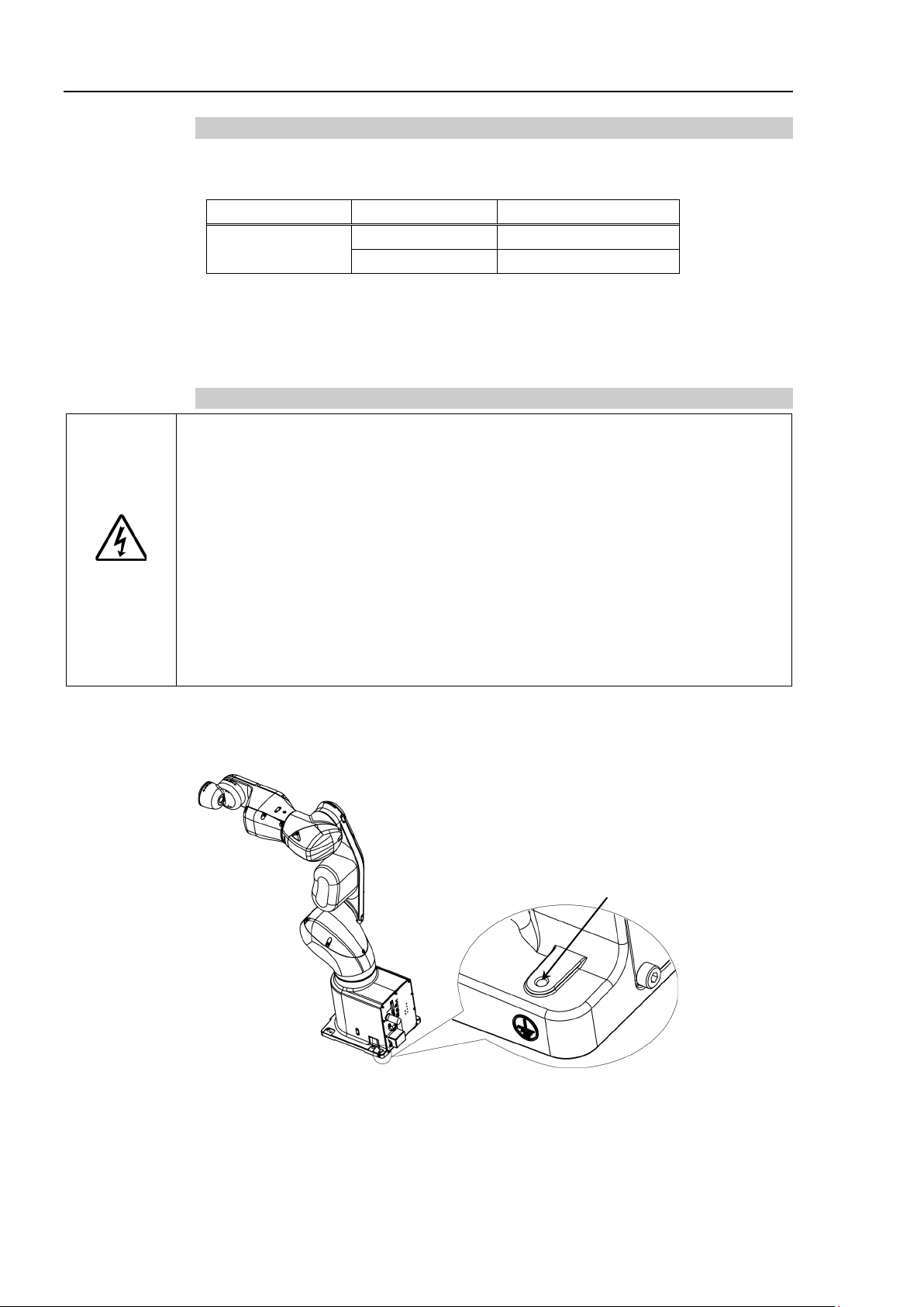
Before loosening the base mounting screws, hold the arm
A
B
C
D
E
fingers from being caught in the Manipulator.
For transport and install procedures, follow the steps
described in this manual.
Do not enter the operation area while the Manipulator is
moving. The robot arm may collide against the operator.
This is extremely hazardous and may result in serious
safety problems.
Hazardous voltage exists while the Manipulator is ON.
To avoid electric shock, do not touch any internal
electric parts.
When releasing the brakes, be careful of the arm falling
due to its own weight.
This warning label is attached on the
optional brake release box.
Only authorized personnel should perform sling work and
operate a crane and a forklift. When these operations are
performed by unauthorized personnel, it is extremely
hazardous and may result in serious bodily injury and/or
severe equipment damage to the robot system.
F
VT Re v. 6 11
You may get your hand or fingers caught when bringing
your hand close to moving parts.
Page 28
Setup & Operation 1. Safety
C
C
C
B
C
C
C
C
C
F
D
A
E
C
G
Protection model
Standard model, Cleanroom model
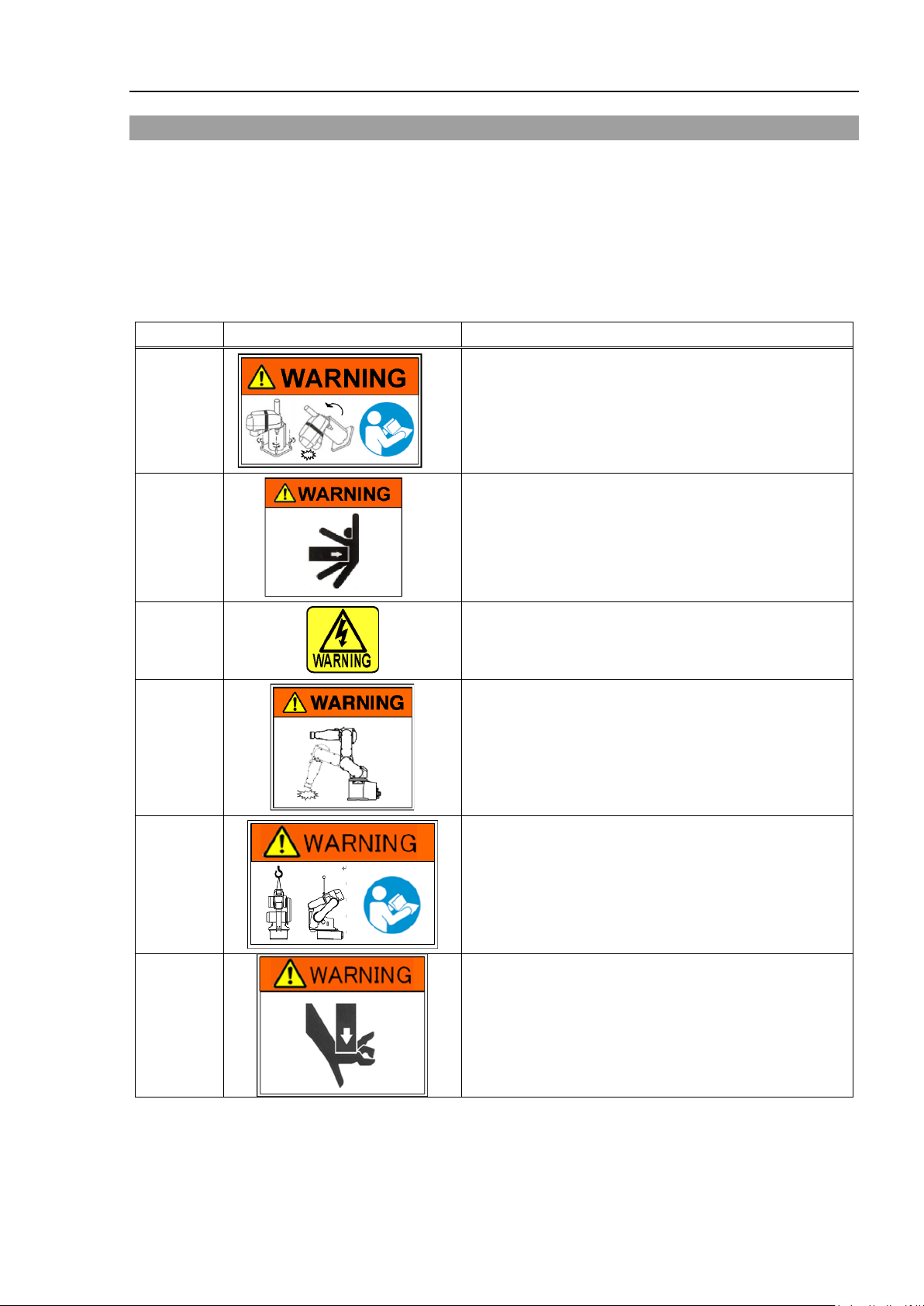
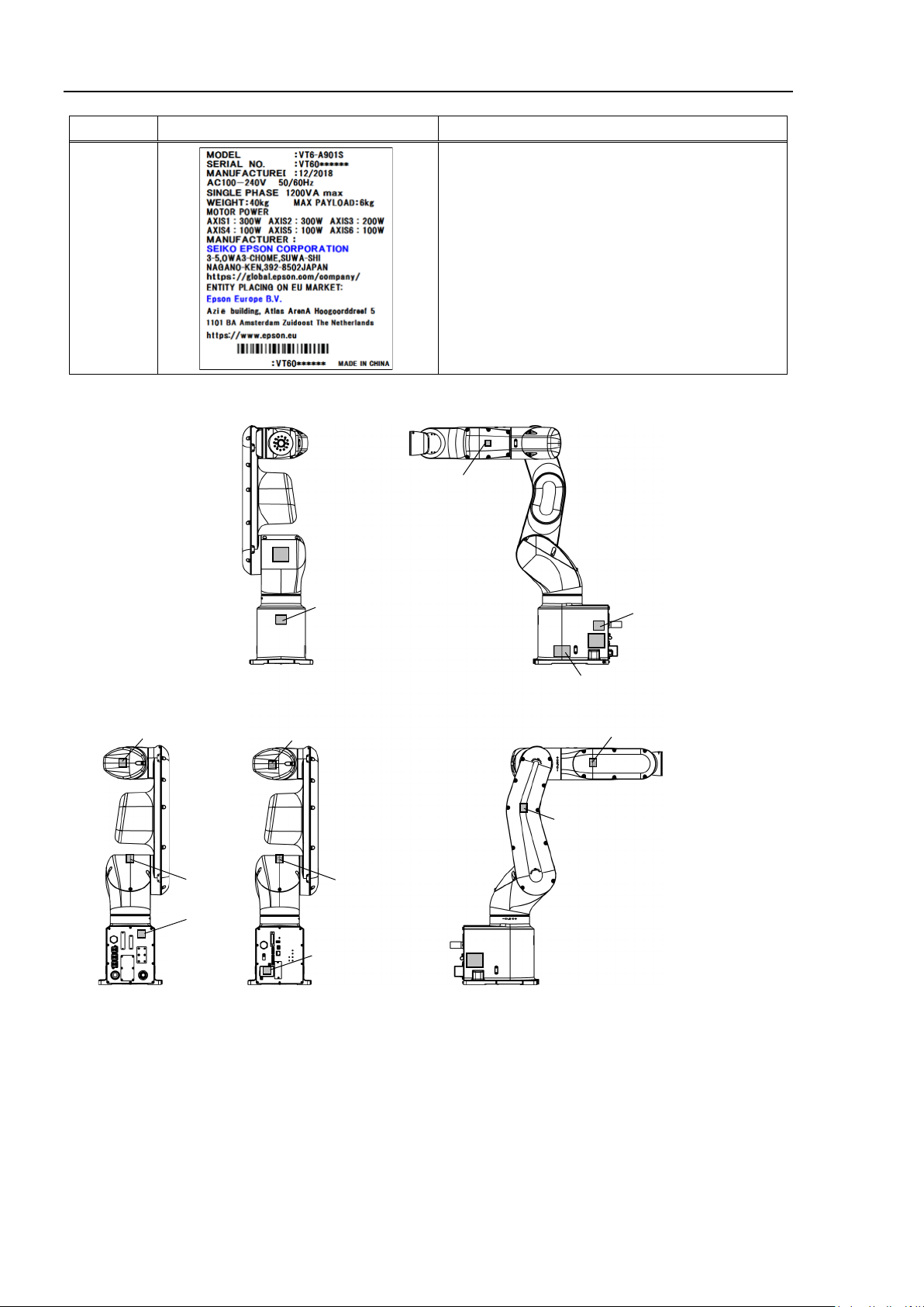
Location Warning Label NOTE
Signature label
S/N (Serial Number) label
G
Location of labels
12 VT Rev.6
Page 29
2. Specifications
Mounting type
: Table Top mounting
R
: Ceiling mounting
W
: Wall mounting
Environment
S
: Standard model
C
: Cleanroom model
P
: Protection model (IP67)
Arm length
Payload
6
: 6 kg
Brake equipment
1
: Brakes on all joints
2.1 Features of VT series Manipulators
The VT series Manipulators are Controller integrated Manipulators.
The features of the VT series Manipulators are as follows:
For Device design and tooling
- There is no external Controller
No installation space required for an external Controller.
No design is required for external Controller installation or tooling.
- No robot to Controller external cables
There are no external cables required between the robot and Controller.
For Maintenance
- There are no motor unit batteries for the robot
No longer necessary to connect external devices for battery replacement.
- Easy to replace the Manipulator
2.2 Model Number
VT6-A90 1 □ □
Setup & Operation 2. Specifications
For details on the specifications, refer to Setup & Operation: 2.7 Specifications.
□
90 : 920 mm
VT Re v. 6 13
Page 30
Setup & Operation 2. Specifications
Joint #1
Base
Arm #1
(Lower Arm)
Arm #2
Arm #4
Joint #6
Joint #3
Joint #4
Joint #5
Arm #6
Joint #2
Arm #5
Arm #3
LED Lamp
(This lamp lights up
while the motors are ON.)
NOTE
2.3 Part Names
When the LED lamp is lighting or the Controller power is ON, current is being applied to
the Manipulator. (The LED lamp may not be seen depending on the Manipulator’s posture.
Be very careful.)
Performing any work with the power ON is extremely hazardous and it may result in electric
shock and/or improper function of the robot system. Make sure to turn OFF the Controller
power before the maintenance work.
14 VT Rev.6
Page 31

Standard model
TP Port
EMERGENCY Connector
Power Supply Cover
(AC power connector inside)
I/O (Input) Connector
I/O (Output) Connector
LAN (Ethernet) Connector
Port of PC for development
RESET switch
MEMORY Port
OPTION Cover
(OPTION connector inside)
TP Port
EMERGENCY Connector
Power Supply Cover
(AC power connector inside)
I/O (Input) Connector
I/O (Output) Connector
LAN (Ethernet) Connector
Port of PC for development
RESET switch
MEMORY Port
OPTION Cover
(OPTION connector inside)
Exhaust port
Fitting for ø12 mm pneumatic tube
TP Port
I/O Connector
Power cord
EMERGENCY
Connector
LAN (Ethernet) Connector
Port of PC for
development
MEMORY Port
OPTION Cover
(OPTION connector inside)
Setup & Operation 2. Specifications
Cleanroom model
Protection model
VT Re v. 6 15
Page 32
Setup & Operation 2. Specifications
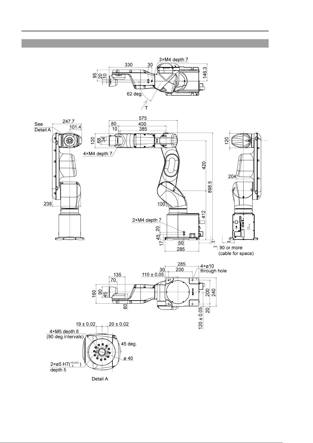
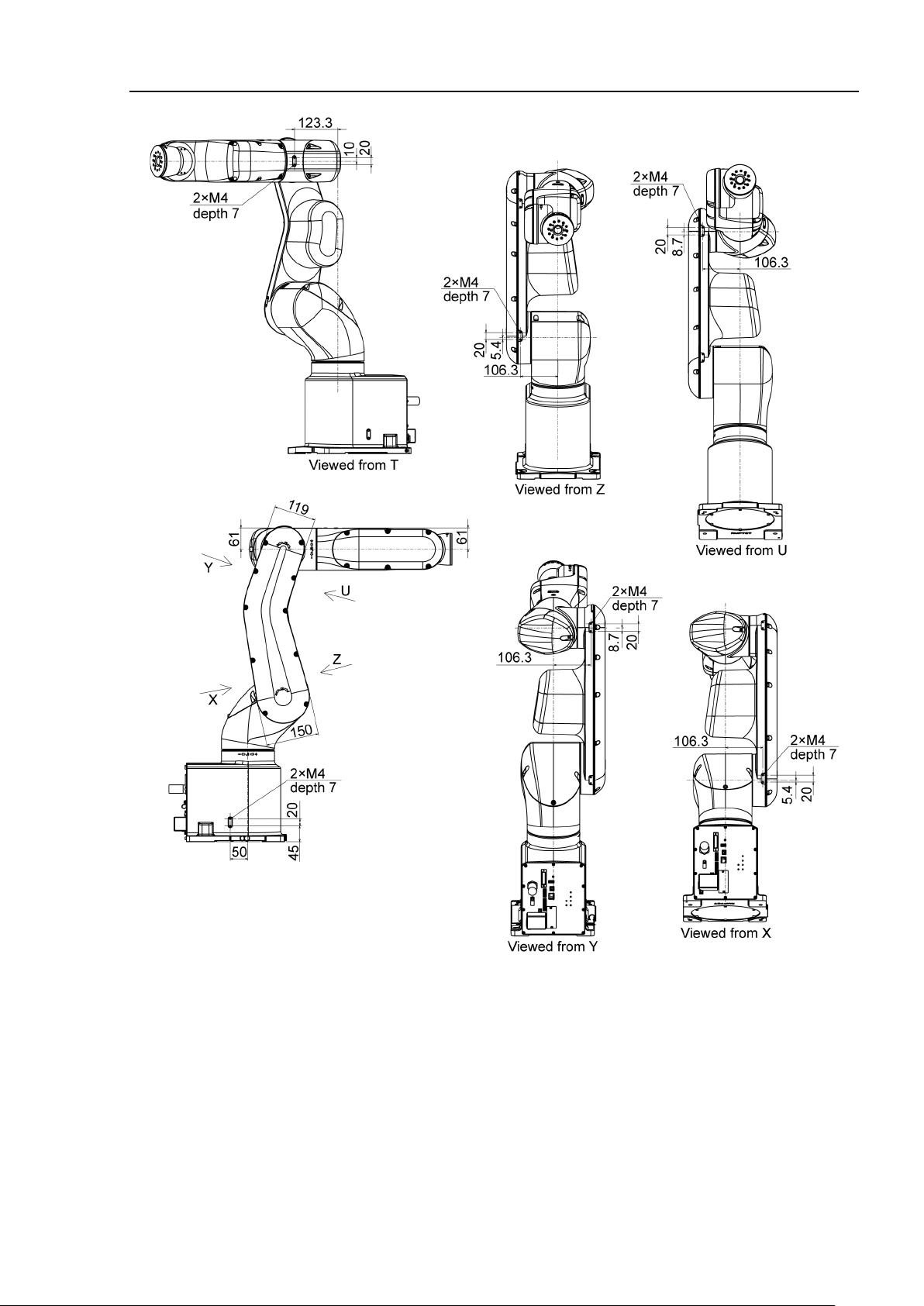
2.4 Outer Dimensions
16 VT Rev.6
Page 33
Setup & Operation 2. Specifications
[Unit: mm]
VT Re v. 6 17
Page 34
Setup & Operation 2. Specifications
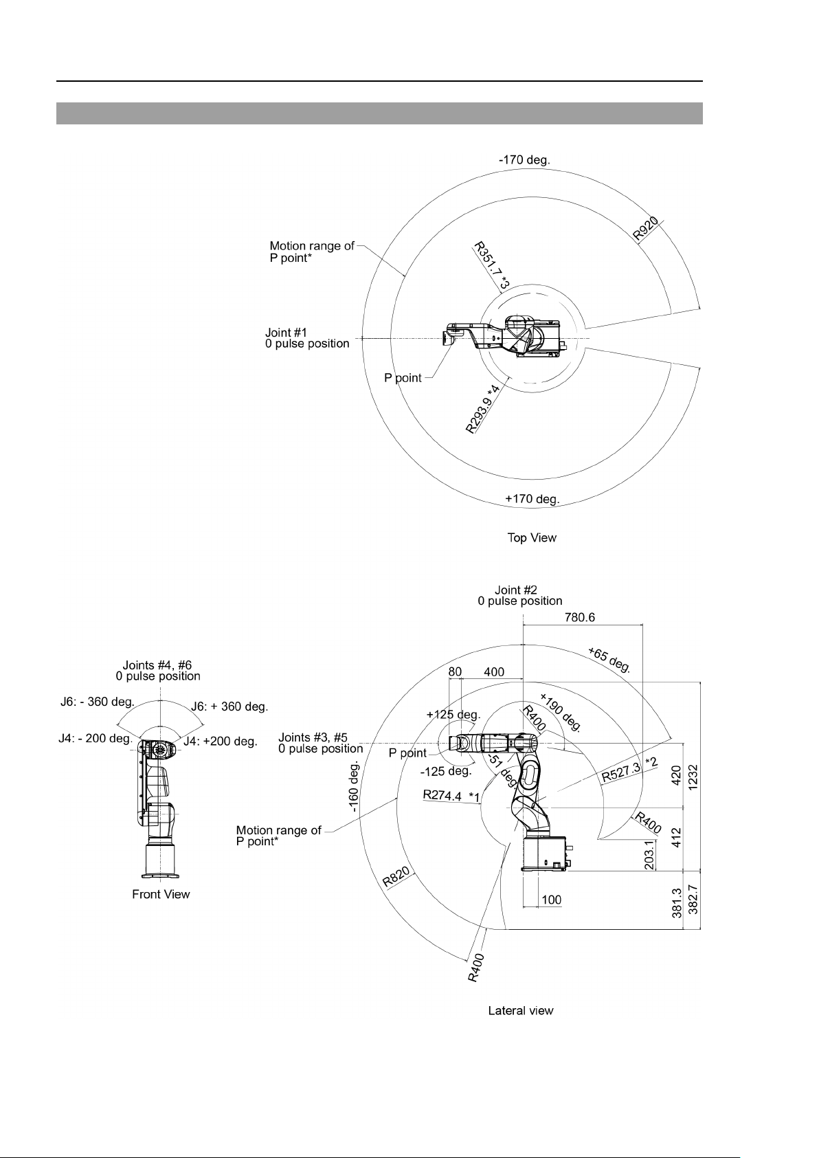
2.5 Standard Motion Range
[Unit: mm]
(deg.=°)
18 VT Rev.6
Page 35

Setup & Operation 2. Specifications
Pay attention to the arm pose of
operating the Manipulator. Arm #5 moves keeping a constant angle regardless
of the arm pose. Depending on the arm pose of the basic arms, the wrist may
collide with the Manipulator. The collision may cause equip
malfunction of the Manipulator.
* P point : Intersection of the rotation centers for Joints #4, #5, and #6
*1 : P point from top with Joint #3 declining −51° (Joint #2 center – P point center)
*2 : P point from top with Joint #3 tilting up +190° (Joint #2 center – P point center)
*3 : P point from lateral with Joint #3 declining +190° (Joint #1 center – P point center)
*4 : P point from lateral with Joint #3 tilting up –51° (Joint #1 center – P point center)
■
the basic arms (Arms #1, #2, and #3) when
CAUTION
ment damage and/or
VT Re v. 6 19
Page 36
Setup & Operation 2. Specifications
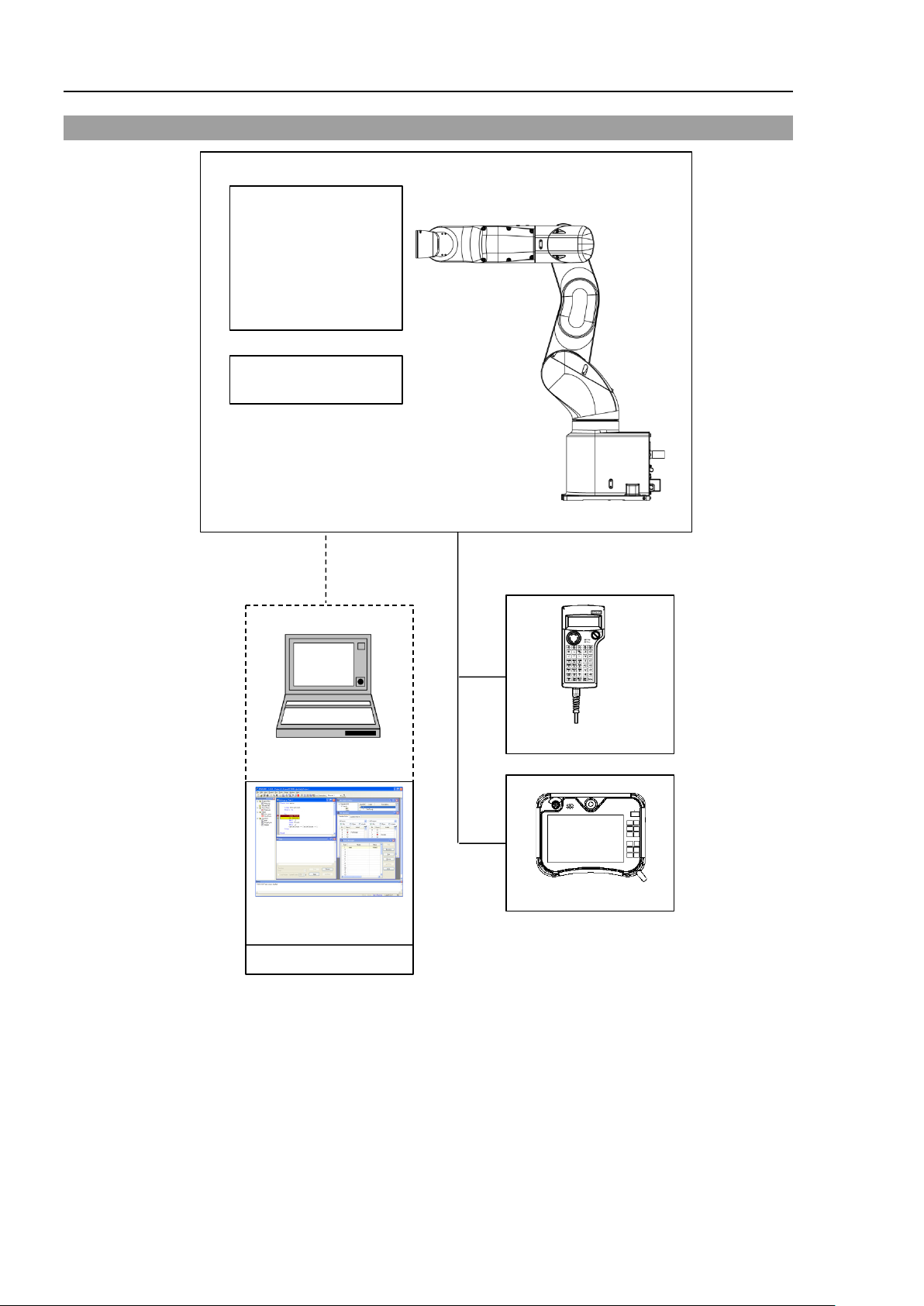
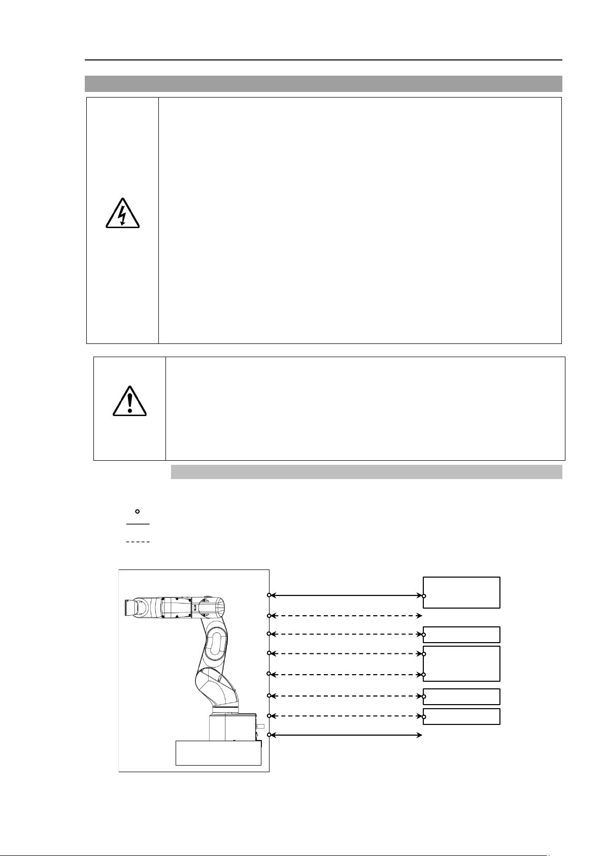
VT6
Standard
Standard I/O
Remote I/O
Ethernet
USB (for save)
USB (for development)
ModBus
Fieldbus
Slave
Option
TP2
TP3
*2
*3
Option: Teaching Pendant
Windows *1
EPSON RC+ 7.0
Software
USB 2.0
or Ethernet
Option
2.6 System Example
*1 EPSON RC+ 7.0 supports the following OS
Windows 7 Professional Service Pack 1
Windows 8.1 Pro (EPSON RC+7.0 Ver.7.1.0 or later)
Windows 10 Pro (EPSON RC+7.0 Ver.7.2.0 or later)
*2 Either teaching pendant is available.
*3 When connecting to VT series Manipulators, specified convert cable is necessary.
20 VT Rev.6
Page 37

2.7 Specifications
Item
Specifications
Model Number
VT6-A901*
VT6-A901*R
VT6-A90*W
Model Name
VT6L
Mounting type *1
Table Top mounting
Ceiling mounting
Wall mounting
Standard
Cleanroom
40 kg: 89 lbs.
(not include the mass of cables or shipping jigs)
42 kg: 92 lbs.
(include the mass of cables or shipping jigs)
Driving method
All joints
AC servo motor
Joint #1
166.2°/s
Joint #2
122.5°/s
Joint #3
141.2°/s
Standard
Cleanroom
Protection
190.0°/s
Joint #5
296.8°/s
Standard
Cleanroom
Protection
234.5°/s
Maximum synthetic speed
4563 mm/s
Repeatability
Joints #1 to #6
± 0.1 mm
Joint #1
± 170°
± 30°
Joint #2
− 160° to + 65°
Joint #3
− 51° to + 190°
Joint #4
± 200°
Joint #5
± 125°
Joint #6
± 360°
Joint #1
± 8488472
±1497966
Joint #2
− 9986438 to + 4056990
Joint #3
− 2366604 to + 8816759
Joint #4
± 8128764
Joint #5
± 4599018
Joint #6
± 13410735
Joint #1
0.0000200°/pulse
Joint #2
0.0000160°/pulse
Joint #3
0.0000215°/pulse
Joint #4
0.0000246°/pulse
Joint #5
0.0000271°/pulse
Joint #6
0.0000268°/pulse
Joint #1
300 W
Joint #2
300 W
Joint #3
200 W
Joint #4
100 W
Joint #5
100 W
Joint #6
100 W
Rated.
3 kg
Max.
6 kg
Joint #4
12 N·m (1.22 kgf·m)
Joint #5
12 N·m (1.22 kgf·m)
Joint #6
7 N·m (0.71 kgf·m)
Joint #4
0.3 kg·m2
Joint #5
0.3 kg·m2
Joint #6
0.1 kg·m2
Mass
Protection
Setup & Operation 2. Specifications
Max.
operating
Joint #4
speed *2
Joint #6
Max. motion range
Max. pulse range
268.7°/s
293.2°/s
Resolution
Motor rated capacity
Payload *3
Allowable moment
Allowable moment of
inertia *4 (GD
VT Re v. 6 21
2
/4)
Page 38
Setup & Operation 2. Specifications
Item
Specifications
Ambient Temperature
5 to 40 °C
Ambient relative
humidity
Vibration
4.9 m·s2 (0.5 G) or less
Noise level *6
L
Aeq
= 70 dB (A) or under
Environment
Standard, Cleanroom *7, Protection (IP67) *8
Speed
(5) 100
Accel *9
(5, 5) 120, 120
SpeedS
(50) 2000
AccelS *10
(200) 10000
(10000, 10000, 10000, 10000, 10000, 10000)
65535, 65535, 65535, 65535, 65535, 65535
Weight
3 (6)
Inertia
0.03 (0.1)
Development
Environment
Programming
Language
Standard 6 joints simultaneous control
Digital AC servo control
PTP (Point-To-Point control)
CP (Continuous Path control)
PTP motion : Programmable in the range of 1 to 100%
(Actual value to be manually entered.)
PTP motion : Programmable in the range of 1 to 100%
(Actual value to be manually entered.)
EMERGENCY STOP:
Redundant (Category 3) Supported for external power supply
Standard I/O
Manipulator)
Input: 8 points
SError, Warning
Input: 256 points
Enable to add only one more module
TP Connection Port
Supported for teach pendant (Option: TP2, TP3)
USB B connector
Supported for USB 2.0 High Speed / Full Speed
Connection Port
Supported for USB 2.0 High Speed / Full Speed
Supported for 10/100 Mbps
Available up to 8 ports
RESET Switch
Enable to use for reset of system
Environmental
requirements *5
Default values
(Max. setting
values)
Motion
Control
Fine
Joint Control
Positioning Control
Speed Control
10 ~ 80 % RH (no condensation)
EPSON RC+ 7.0
SPEL+ (multi-tasking robot language)
CP motion : Programmable
External
Interface
Acceleration/
Deceleration
Control
EMERGENCY
(Rear side of
I/O
Remote I/O
(Remote
functions are
applied to
Standard I/O)
Field bus Slave
(Option)
PC Connection Port
Auto acceleration/deceleration
CP motion : Programmable
Redundant (Category 3) Supported for internal/external power
supply
Safeguard System:
Input: 24 points
Output: 16 points
Non-polar, Supported for both Sink and Source
Program, 3 points
Start, Stop, Pause, Continue, Reset
Output: 8 points
Ready, Running, Paused, ErrorEStopOn, SafeguardOn,
Output: 256 points
USB Memory
USB A connector
Ethernet Port
22 VT Rev.6
Page 39

Setup & Operation 2. Specifications
Item
Specifications
Display
Mode Display LED
TEACH, AUTO, PROGRAM, TestMode, Error, E-STOP
Save to USB memory
Save in RC+ (PC)
Voltage
100 to 240 VAC
Phase
Single phase
Frequency
50 / 60 Hz
Momentary Power Interrupt
Less than 10 ms
Rated Capacity
1, 200 VA
Peak Current
(When AC power is turned ON)
Leak Current
Max. 10 mA
Ground Resistance
Less than 100Ω
CE Mark:
NFPA 79 (2007 Edition)
Cleanliness level
:
ISO Class 4 (ISO14644-1)
Exhaust system
:
Fitting for ø12 mm pneumatic tube
60 L/min vacuum
Exhaust tube
:
Polyurethane tube Outer diameter: ø12 mm (Inner diameter: ø8 mm)
Controller Status Save
Max. 60A (Less than 2 ms)
EMC Directive, Machinery Directive, RoHS Directive
Safety standard
*1: Mounting types other than “Table Top mounting”, “Ceiling mounting”, and “Wall mounting” are out of
specification. For Cleanroom model and Protection model, only Table Top mounting is available.
If you prefer other mounting types, please contact the supplier of your region.
KC Marking / KCs Marking
ANSI/RIA R15.06-2012
*2: In case of PTP control
*3: Do not apply the load exceeding the maximum payload.
*4: If the center of gravity is at the center of each arm. If the center of gravity is not at the center of each arm,
set the eccentric quantity using INERTIA command.
*5: For details of the environmental requirements, refer to the Setup & Operation 3.1 Environmental Conditions.
*6: Conditions of Manipulator at measurement are as follows:
Operating conditions: Under rated load, all arms simultaneous motion, maximum speed, maximum
acceleration, VT6L: duty 50%
Measurement point: 1000 mm apart from the rear of Manipulator
*7: The exhaust system in the Cleanroom-model Manipulator draws air from the base interior and arm cover
interior.
A crack or other opening in the base unit can cause loss of negative air pressure in the outer part of the arm,
which can cause increased dust emission.
VT Re v. 6 23
Page 40

Setup & Operation 2. Specifications
10000
8000
6000
4000
2000
0 1 2 3 4 5 6 (kg) End effector weight
8000
3000
10000
2000
6000
*8 Protection level for the protection-model Manipulators is IP67 (IEC standard). The Manipulators can
be used in environments where the possibility of dust, water, and water-soluble cutting oil falling of the
Manipulator exists.
However, please be careful of the following:
- The Manipulator is not rust-proofed. Do not use the Manipulator in environment where corrosive
liquids exist.
- Fluids that deteriorate the sealing materials, such as organic solvents, acids, alkalis, and chlorine
cutting fluids, cannot be used
- The Manipulator cannot be used for underwater operations.
<Reference>
- IP67 of IEC standard
[Protection level against ingress of solid objects]
Totally protected against dust.
[Protection level against liquids]
Protection from ingress of water in harmful quantity when the Manipulator is immersed in
water for 30 minutes under the condition that the highest point of the Manipulator is located
0.15 m below the surface of the water and the lowest point is located 1 m below the surface
of the water. (Tested while the Manipulator is stopped.)
*9: In general use, Accel setting 100 is the optimum setting that maintains the balance of acceleration and
vibration when positioning. Although values larger than 100 can be set to Accel, it is recommended to
minimize the use of large values to necessary motions since operating the Manipulator continuously with
the large Accel setting may shorten the product life remarkably.
*10: Maximum AccelS setting value varies depending on the load. Refer to the table below for details.
Setting the value which exceeds the maximum AccelS causes an error. In such a case, check the setting
value.
Maximum AccelS setting value
24 VT Rev.6
Page 41

2.8 How to Set the Model
When you need to change the setting of the Manipulator model, be sure to set the
Manipulator model properly.
result in abnormal or no operation of the Manipulator and/or cause safety
problems.
NOTE
The Manipulator model for your system has been set before shipment from the factory.
It is normally not required to change the model when you receive your system.
■
CAUTION
If the custom specifications number (MT***) is described on MODEL of the signature label
(S/N label), the Manipulator has custom specifications.
The custom specifications may require a different configuration procedure; check the
custom specifications number (MT***) and contact the supplier of your region when
necessary.
The Manipulator model can be set from software.
Refer to the following manual.
Chapter Robot Configuration in the EPSON RC+ User’s Guide.
Setup & Operation 2. Specifications
Improper setting of the Manipulator model may
VT Re v. 6 25
Page 42

Setup & Operation 3. Environments and Installation
Item
Conditions
Ambient temperature
5 to 40°C (with minimum temperature variation)
Ambient relative humidity
10 to 80% (with no condensation)
1 kV or less (Signal wire)
Electrostatic noise
4 kV or less
Item
Conditions
organic solvents, acids, alkalis, and
and metal *2.
NOTE
3. Environments and Installation
3.1 Environmental Conditions
A suitable environment is necessary for the robot system to function properly and safely.
Be sure to install the robot system in an environment that meets the following conditions:
First transient burst noise
Environment · Install indoors.
Manipulators are not suitable for operation in harsh environments such as painting areas,
etc. When using Manipulators in inadequate environments that do not meet the above
conditions, please contact the supplier of your region.
For the Protection model Manipulator, be sure to install the robot system in an environment
that also meets the following conditions:
2 kV or less (Power supply wire)
· Keep away from direct sunlight.
· Keep away from dust, oily smoke, salinity, metal
powder or other contaminants.
· Keep away from flammable or corrosive solvents
and gases.
· Keep away from water.
· Keep away from shocks or vibrations.
· Keep away from sources of electric noise.
- Keep away from strong electric or magnetic fields.
Environment - Install indoors.
26 VT Rev.6
- Keep away from direct sunlight.
- Keep away from salinity or other contaminants.
- Keep away from flammable or corrosive solvents
(including water) *
- Keep away from
chlorine cutting fluids.
- Do not use in water.
- Keep away from shock or vibration.
- Keep away from sources of electric noise.
- Available under the environment with dust, oily smoke,
1
and gases.
Page 43

Setup & Operation 3. Environments and Installation
WARNING
Use an earth leakage breaker on the AC power cable of the
electric shock and circuit breakdown caused by
CAUTION
When cleaning the Manipulator, do not rub it strongly with alcohol or
It may lose luster on the coated face.
VT6-A901*
Max. Reaction torque on the horizontal plate
500
Max. Horizontal reaction force
500
Max. Vertical reaction force
3100
*1 The Manipulator is mainly made of iron and aluminum. It is not rust-proofed.
Do not use the Manipulator under conditions where it can be exposed to water or any
other corrosive liquid (including water).
*2 Any contaminants that can deteriorate sealing performance of nitrile rubber oil sealing,
O-rings, packing seals and liquid gasket should be avoided.
Special Environmental Conditions
The protective seals are attached on the Protection model Manipulator to prevent dust, water,
etc. from the outside. Follow the precautions in use environment described below.
Surface of the Manipulator has general oil resistance. However, if your requirements
specify that the Manipulator must withstand certain kinds of oil, please contact the supplier
of your region.
Rapid change in temperature and humidity can cause condensation inside the Manipulator.
If your requirements specify that the Manipulator handles food, please contact the supplier
of your region to check whether the Manipulator will damage the food or not.
The Manipulator cannot be used in corrosive environments where acid or alkaline is used.
In a salty environment where the rust is likely to gather, the Manipulator is susceptible to
rust.
■
■
3.2 Base Table
A base table for anchoring the Manipulator is not supplied. Please make or obtain the base
table for your Manipulator. The shape and size of the base table differs depending on the
use of the robot system. For your reference, we list some Manipulator table requirements
here.
Base table is necessary for support not only the mass of the Manipulator but also dynamic
motion when operating at the fastest speed. Provides enough beams to give sufficient
strength.
The torque and reaction force produced by the movement of the Manipulator are as follows:
Manipulator to avoid
short circuit.
benzene.
The threaded holes required for mounting the Manipulator base are M8. Use mounting
bolts with specifications conforming to ISO898-1 property class: 10.9 or 12.9.
For dimensions, refer to Setup & Operation: 3.3 Mounting Dimensions.
VT Re v. 6 27
Page 44

Setup & Operation 3. Environments and Installation
I/O (Input) Connector
11
54
37
13
11
24
I/O(Output)
Connector
EMERGENCY Connector
9
34
AC Power Connector
I/O Connector
15.35
53.05
67
12.55
EMERGENCY Connector
To ensure safety, a safeguard must be installed
For details on the
The plate for the Manipulator mounting face should be 20 mm thick or more and made of
steel to reduce vibration. The surface roughness of the steel plate should be 25 μm or less.
The table must be secured on the floor or wall to prevent it from moving.
The Manipulator must be installed horizontally.
When using a leveler to adjust the height of the base table, use a screw with M16 diameter
or more.
If you are passing cables through the holes on the base table, see the figures below.
Standard model, Cleanroom model
(Unit: mm)
Protection model
■
WARNING
for the robot system.
safeguard, refer to the EPSON RC+ User’s Guide.
28 VT Rev.6
Page 45

3.3 Mounting Dimensions
NOTE
Mounting Area
Be sure to have the following space available in addition to the space for mounting the
Manipulator and peripheral equipment.
Space for teaching points
Space for maintenance and inspections
(Ensure a space to open the covers and plates for maintenance.)
Space for cables
The minimum bend radius of the power cable is 90 mm. When installing the cable, be sure
to maintain sufficient distance from obstacles. In addition, leave enough space for other
cables so that they are not bent forcibly.
Ensure distance to the safeguard from the maximum motion range is more than 100 mm.
Setup & Operation 3. Environments and Installation
[Unit: mm]
VT Re v. 6 29
Page 46

Setup & Operation 3. Environments and Installation
Only authorized personnel
forklift. When
extremely
equipment damage to the
Stabilize the Manipulator with your hands when hoisting it. Unstable hoisting is
extremely hazardous and may result in serious bodily injury and/or severe
equipment damage to the robot system as the fall of the Manipulator.
Using a cart or similar equipment, transport the Manipulator in the same manner
as it was delivered.
When removing the anchor bolts, support the Manipulator to prevent falling
.
Removing the anchor bolts without supporting the
fingers, or feet caught as the Manipulator may fall
To transport the Manipulator, secure it to the delivery equipment or have at least
2
area
cause your hands and fingers caught.
DO NOT hold the bottom of the base by hand.
Manipulator mass
VT6-A901**
Standard, Cleanroom
Approx. 40 kg: 89 lbs.
Protection
Approx. 42 kg: 92 lbs.
When transporting the Manipulator, a
Excessive vibration or shock may cause equipment damage and/or
of the Manipulator.
Stabilize the Manipulator with your hands when hoist
extremely hazardous and may result in fall of the Manipulator.
When transporting the Manipulator for a long distance, secure it to
equipment directly so that the Manipulator never falls
If necessary, pack the Manipulator in the same style as
3.4 Unpacking and Transportation
THE INSTALLATION SHALL BE PREFORMED BY QUALIFIED INSTALLATION
PERSONNEL AND SHOULD CONFORM TO ALL NATIONAL AND LOCAL CODES.
WARNING
■
should perform sling work and operate a crane and a
these operations are performed by unauthorized personnel, it is
hazardous and may result in serious bodily injury and/or severe
robot system.
■
■
■
Manipulator may get hands,
over.
■
people to hold it by hand. Also, do not hold the bottom of the base (the shaded
in the figure). Holding the area by hand is extremely hazardous and may
over
CAUTION
■
■
■
30 VT Rev.6
void excessive vibration or shock.
malfunction
ing it. Unstable hoisting is
the delivery
over.
it was delivered.
Page 47

3.5 Installation Procedure
To ensure safety, a safeguard must be installed for the robot system. For details
on the safeguard, refer to the Installation and Design Precautions in the Safety
chapter of the EPSON RC+ User’s Guide.
Install the Manipulator in a location with sufficient space so that a tool or a work
piece does not touch a wall or a safeguard when the Manipulator extends its arm
fully while holding a work piece. Installing the Manipulator at a locati
insufficient space is extremely hazardous and may result in serious bodily injury
and/or severe equipment damage to the robot system as a tool or a work piece
may collide with a wall or a safeguard.
Anchor the Manipulator before turning ON the power or operating the Manipulator.
Turning ON the power or operating the Manipulator that is not anchored is
extremely hazardous and may result in serious bodily injury and/or severe
equipment damage to the robot system as the Manipulator may fall down.
Before installing and operating the Manipulator, make sure that all parts of the
Manipulator are in place and have no external defects. Missing or defective parts
may cause improper operation of the
Manipulator is extremely hazardous and may result in serious bodily injury and/or
severe equipment damage to the robot system.
The
utilities, other
points.
Vibration
installation table.
If the
acceleration and deceleration settings.
Install the
The Manipulator
caught and/or have equipment damage
The installation shall be made by qualified installation personnel and should conform to all
national and local codes.
■
■
WARNING
■
■
Setup & Operation 3. Environments and Installation
on with
■
■
Manipulator must be installed to avoid interference with buildings, structures,
(resonance) may occur during operation depending on rigidity of the
vibration occurs, improve rigidity of the table or change the speed or
CAUTION
■
VT6-A901**:
Standard, Cleanroom model: Approx. 40 kg: 89 lbs.
Protection model: Approx. 42 kg: 92 lbs.
Table Top Mounting Manipulator with two or more people.
Manipulator. Improper operation of the
machines and equipment that may create a trapping hazard or pinch
mass are as follows. Be careful not to get hands, fingers, or feet
d by a fall of the Manipulator.
VT Re v. 6 31
Page 48

Setup & Operation 3. Environments and Installation
There are four threaded holes for the
Manipulator base
Use
strength of
12.9.
Tightening torque:
32
Screw Hole (depth 18 mm or more)
Plain
Washer
Spring
Washer
17 mm
4-M8×35
Item
Specification
Voltage
100 to 240 VAC
(Input voltage should be with in ±10 % of the rated voltage.)
Phase
Single phase
Frequency
50/60 Hz
Momentary Power Interrupt
Less than 10 msec.
Rated Capacity
1,200VA
Peak Current
(When AC power is turned ON)
Leak Current
Max. 10 mA
Ground Resistance
100 Ω or less
NOTE
Mounting bolt
For the dimensions, refer to Setup & Operation 3.3 Mounting Dimensions.
.
M8 mounting bolts conforming to the
ISO898-1 property class 10.9 or
.0 ± 1.6 N·m (314 ± 16 kgf·cm)
Cleanroom Model
When using the Manipulator in the cleanroom, follow the steps below before the installation.
(1) Unpack the Manipulator outside of the cleanroom.
(2) Secure the Manipulator to delivery equipment such as a pallet with bolts so that the
Manipulator does not fall over.
(3) Wipe off the dust on the Manipulator with a little alcohol or distilled water on a lint-
free cloth.
(4) Transport the Manipulator into the cleanroom.
(5) Secure the Manipulator to the base table.
3.6 Power Supply
■ There is no power switch on the Manipulator. Right after inserting power plug
WARNING
to power, the Robot System turns ON.
Be careful about electric shock when inserting power plug.
3.6.1 Specifications
Ensure that the available power meets following specifications.
32 VT Rev.6
Max. 60A (Less than 2 ms)
Page 49
for power connecting cable.
Item
Specification
AC power wire (2 cables)
Black, White
Ground wire
Green/Yellow
Cable length
5 m
Terminal
M4 round solderless terminal
AC Power Cable Clamp
WARNING
Setup & Operation 3. Environments and Installation
3.6.2 AC Power Cable
Make sure that the operations are done by a qualified personal.
■
■ Be sure to connect the earth wire (green/yellow) of the AC power cable to the
earth terminal of the factory power supply.
Also, we recommend to ground directly via a hole on the base to ground the
Manipulator completely.
The equipment must be grounded properly at all times to avoid the risk of
electric shock.
■ Always use a plug or a disconnecting device
Never connect the Controller directly to the factory power supply.
■ Select a plug or a disconnecting device which conforms to safety standards of
each country.
When connecting the connecter of AC cable to the Manipulator, make sure to insert
completely.
Connection Specification of Cable Wire
Use cable clamp on rear side of the Manipulator to fix AC power cable.
(Only for Standard model, Cleanroom model)
VT Re v. 6 33
Page 50
Setup & Operation 3. Environments and Installation
Manipulator
Power
Rated electric current
AC100V
20A
AC200V
10A
Ground resistance must be 100
result in fire and/or electric shock.
■
Do not use the ground line for the Manipulator in common with other ground lines
or grounding electrodes for other electric power, motor power, welding devices,
etc.
or grounding electrodes may result in electric shock and/or malfunction of the
robot system.
■
When using metal ducts, metallic conduits, or distributing racks for cable, ground
in accordance with national and local electric equipment technical standards.
Grounding that
malfunction of
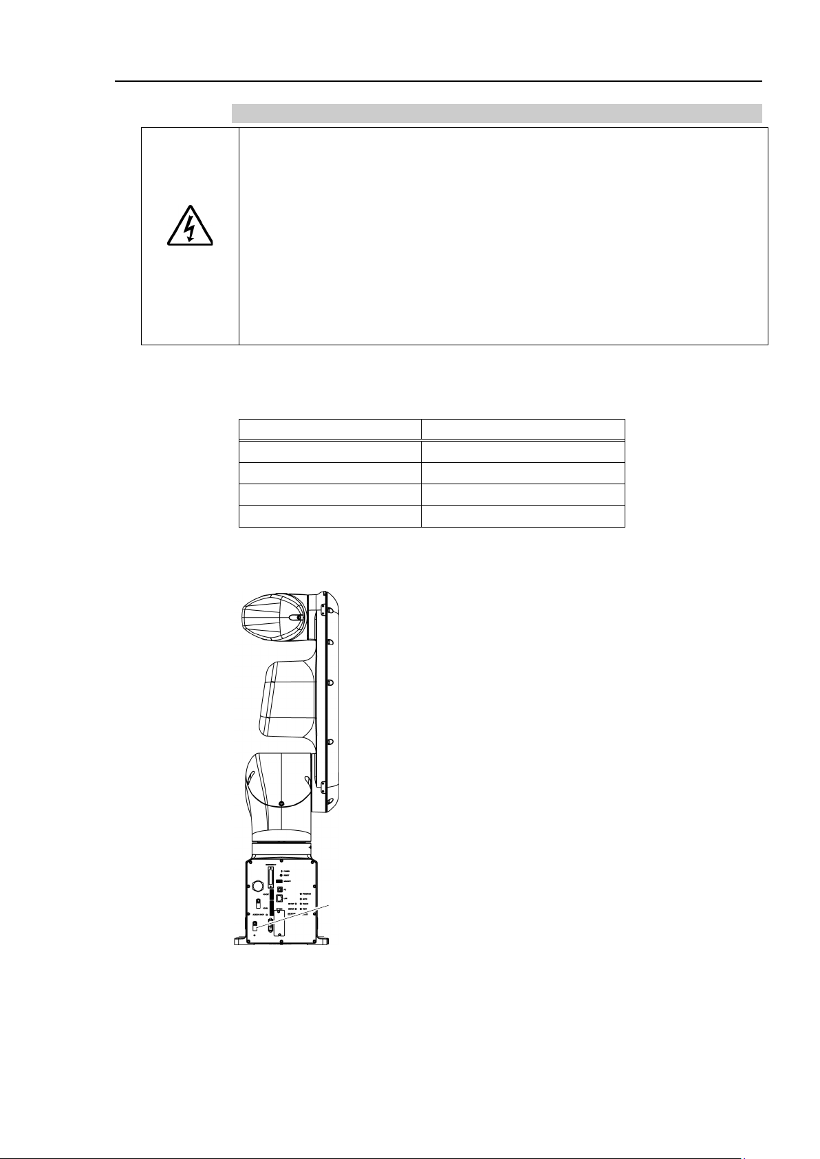
Bolt hole M4
(for grounding)
3.6.3 Breaker
Install an earth leakage circuit breaker or a circuit breaker in the AC power cable line.
For the rated electric current of the circuit breaker, refer to the following set values.
VT6L
If you install a circuit breaker, please select one that can handle the “peak current” described
in the following section.
Setup & Operation 3.6.1 Specifications
The power receptacle shall be installed near the equipment and shall be easily accessible.
3.6.4 Grounding
WARNING
■
Ω or less. Improper ground resistance may
Using the ground line for the Manipulator in common with other ground lines
does not meet the standards may result in electric shock and/or
the robot system.
Follow local regulations for grounding. It is recommended that the core size of the
grounding wire be 5.5 mm
2
or more.
Directly connect the ground line to the Manipulator using bolt hole in the figure below.
34 VT Rev.6
Page 51
3.7 Connecting the Cables
To shut off power to the robot system, disconnect the power plug from the power
source. Be sure to connect the AC power cable to a power receptacle.
DO NOT connect it directly to a factory power source.
■
Before performing any replacement procedure, turn OFF the Controller and
related equipment,
Performing any replacement procedure with the power ON is extremely hazardous
and may result in
■
Be sure to
cables. (Do not
forcibl
cables, disconnection, and/o
Damaged cables, disconnection, or contact failure is extremely hazardous and
may result in electric shock and/or improper function of the robot system.
■
Grounding the
the
improperly connected to ground, it may result in the fire or electric shock.
Detachable connector
Supplied cable
Not supplied cable (Prepare by yourself)
100V-240VAC
Output device
PC for
development
USB memory
Emergency stop, safety door
Manipulator
Teach
Pendant
Input device
Option
Fieldbus I/O
(1) TP connector
(2) EMERGENCY connector
(3)
Memory port
(4)
PC port for
development
(5) LAN (Ethernet)
(6) I/O(Input) connector
(7) I/O(Output) connector
(8) AC power connector
■
connect the cables properly. Do not allow unnecessary strain on the
WARNING
y.) The unnecessary strain on the cables may result in damage to the
Manipulator is done by connecting with Power cable. Ensure that
Power cable and ground wire are correctly connected. If the ground wire is
Setup & Operation 3. Environments and Installation
and then disconnect the power plug from the power source.
electric shock and/or malfunction of the robot system.
put heavy objects on the cables. Do not bend or pull the cables
r contact failure.
■
Make sure that the serial numbers on each equipment match. Improper
connection between the Manipulator and Controller may not only cause
improper function of the robot system but also serious safety problems.
■
CAUTION
Before connecting the connector, make sure that the pins are not bent.
Connecting with the pins bent may damage the connector and result in
malfunction of the robot system.
3.7.1 Connection Example
Standard model, Cleanroom model
VT Re v. 6 35
Page 52

Setup & Operation 3. Environments and Installation
(1) TP connector
Connect the option Teach Pendant.
For details, refer to the Setup & Operation 10.TP Port.
(2) EMERGENCY
The EMERGENCY connector has inputs to connect the Emergency Stop switch and
the Safety Door switch. For safety reasons, connect proper switches for these input
devices.
For details, refer to the Setup & Operation 12. EMERGENCY.
(3) Memory port
Connect to USB memory.
For details, refer to the Setup & Operation 8. Memory port.
(4) PC for development
Connect the PC for development.
For details, refer to the Setup & Operation 7. Development PC Connection Port
(5) LAN (EtherNet Communication)
Connect the EtherNet cable.
For details, refer to the Setup & Operation 9. LAN (Ethernet Communication) Port.
(6) I/O (Input) connector
This input connector is for output device of the user.
When there is output device, use this connector.
For details, refer to the Setup & Operation 13. Standard I/O connector.
(7) I/O (Output) connector
This output connector is for input device of the user.
When there is input device, use this connector.
For details, refer to the Setup & Operation 13. Standard I/O connector.
(8) AC power connector
Connector for AC power supply to the Manipulator.
For the Cleanroom model Manipulator, an exhaust system is necessary. For details, refer
to Setup & Operation: 2.6 Specifications.
36 VT Rev.6
Page 53

Protection model
Detachable connector
Supplied cable
Not supplied cable (Prepare by yourself)
100V-240VAC
(Connected)
Output device
PC for
development
USB memory
Emergency stop, safety door
Manipulator
Teach
Pendant
Input device
Option
Fieldbus I/O
(1) TP connector
(2) EMERGENCY connector
(3) Memory port
(4) PC port for development
(5) LAN (Ethernet)
(6) I/O connector
(7) AC power connector
Setup & Operation 3. Environments and Installation
(1) TP connector
Connect the option Teach Pendant.
For details, refer to the Setup & Operation 10.TP Port.
(2) EMERGENCY
The EMERGENCY connector has inputs to connect the Emergency Stop switch and
the Safety Door switch. For safety reasons, connect proper switches for these input
devices.
For details, refer to the Setup & Operation 12. EMERGENCY.
(3) Memory port
Connect to USB memory.
For details, refer to the Setup & Operation 8. Memory port.
(4) PC for development
Connect the PC for development.
For details, refer to the Setup & Operation 7. Development PC Connection Port
(5) LAN (EtherNet Communication)
Connect the EtherNet cable.
For details, refer to the Setup & Operation 9. LAN (Ethernet Communication) Port.
(6) I/O connector
This is a connector for connecting input and output devices of the user.
When there is input or output device, use this connector.
For details, refer to the Setup & Operation 13. Standard I/O connector.
VT Re v. 6 37
(7) AC power connector
Connector for AC power supply to the Manipulator.
This is connected at shipment.
Page 54
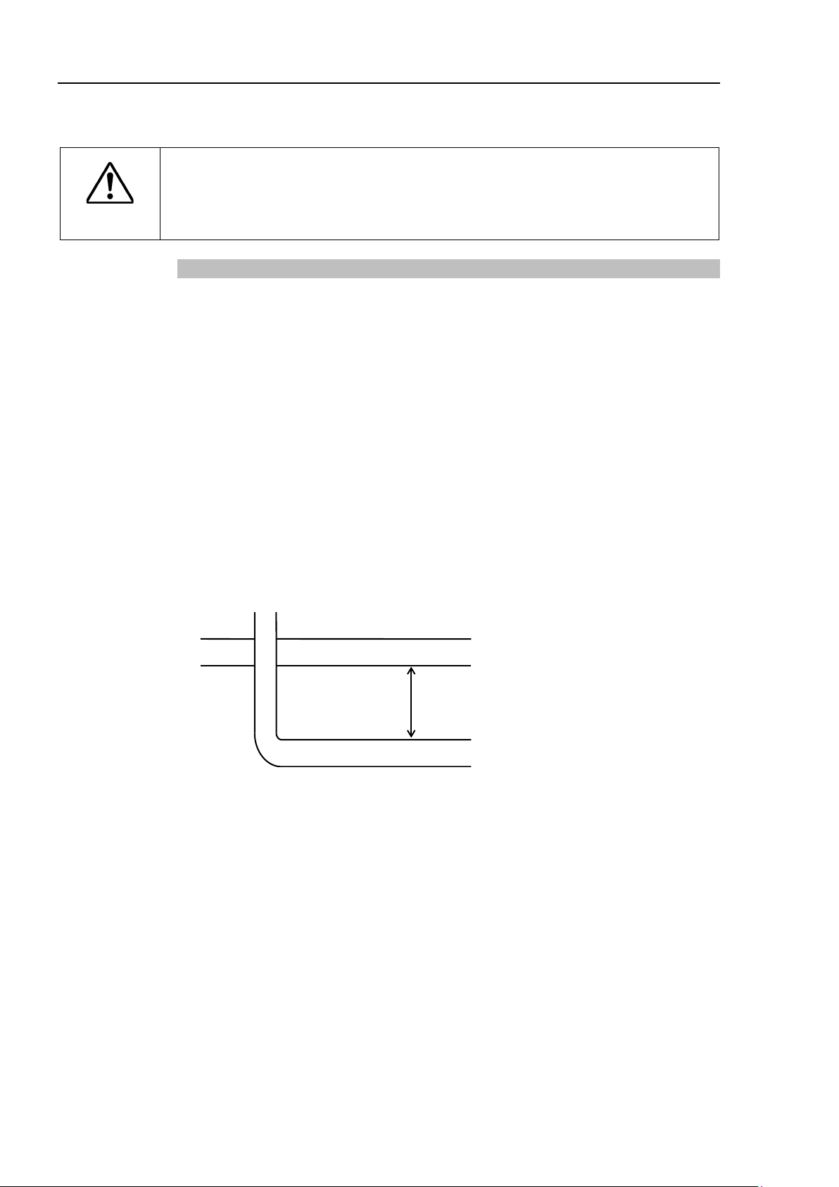
Setup & Operation 3. Environments and Installation
When operating the Manipulator under special environmental conditions (adverse
conditions with dust and oily smoke), do not place the Controller in the same
condition since the Controller does not comply with
equipment damage to a
AC Line duct
DC line duct
As far as possible
For the Protection model Manipulator, also make sure to follow the following precautions.
■
CAUTION
nd/or malfunction of the Controller.
IP67. Doing so may cause
3.7.2 Noise Countermeasures
To minimize electrical noise conditions, the following items must be observed in the
system’s cable wiring:
- The earth wire of the power supply should be grounded. (Ground resistance: 100 Ω or
less) It is important to ground the frame of Manipulator not only for prevention from
electric shock, but also for reducing the influence of electric noise around the
Manipulator. Therefore, be sure to connect the earth wire (yellow/green) of the
Manipulator’s power cable to the ground terminal of the factory power supply. For
details about the plug and AC power cable, refer to the Setup & Operation 3.6 Power
Supply.
- Do not tap power from a power line that connects to any equipment which may cause
noise.
- Do not run AC power lines and DC power lines in the same wiring duct, and separate
them as far as possible. For example, separate the AC motor power line and the
Manipulator power line as far as possible from the sensor or valve I/O lines; and do not
bundle both sets of wiring with the same cable tie. If more than one duct/cable must
cross each other, they should cross perpendicularly. The preferable example is shown
in the right figure.
- Wire as short as possible to the I/O connector and EMERGENCY connector. Use a
shielded cable and clamp the shield to the attached connector interior. Make sure to
keep away from the peripheral noise source as far as possible.
- Make sure that the induction elements used to connect to the Manipulator’s I/O (such as
relays and solenoid valves) are noise suppression parts. If an induction element without
protection against noise is used, make sure to connect a noise suppression part such as a
diode located at the induction element in parallel with it. In selecting noise suppression
parts, make sure that they can handle the voltage and current incurred by the induction
load.
- As they are easily influenced by noise, keep cable such as USB, Ethernet, or fieldbus
away from peripheral noise sources.
38 VT Rev.6
Page 55

3.8 Relocation and Storage
Only authorized personnel
forklift. When
extremely
equipment damage to the robot system.
■
Stabilize the
extremely hazardous and may result in serious bodily injury and/or severe
equipment damage to the robot system as the fall of the Manipulator.
When removing the anchor bolts, support the Manipulator to prevent falling over.
Removing the anchor bolts without supporting the Manipulator may get hands,
fingers, or feet caught as the Manipulator may fall
To transport the Manipulator, secure it to the delivery equipment or have at least
2
screened parts in the figure). Holding these parts by hand is extremely
hazardous and may cause
DO NOT hold the bottom of the base by hand.
Manipulator mass
VT6-A901**
Protection
Approx. 42 kg: 92 lbs.
Make sure not to hold the
Also, a
Excessive vibration or shock may cause equipment damage and/or malfunction
of the Manipulator.
Stabilize the Manipulator with your hands when hoisting it. Unstable hoisting is
extremely hazardous and may result in fall of the Manipulator.
When transporting the Manipulator for a long distance, secure it to the delivery
equipment so that the Manipulator
Manipulator in the same way as it was delivered.
3.8.1 Precautions for Relocation and Storage
Observe the following when relocating, storing, and transporting the Manipulators.
THE INSTALLATION SHALL BE PREFORMED BY QUALIFIED INSTALLATION
PERSONNEL AND SHOULD CONFORM TO ALL NATIONAL AND LOCAL CODES.
Setup & Operation 3. Environments and Installation
WARNING
■
these operations are performed by unauthorized personnel, it is
hazardous and may result in serious bodily injury and/or severe
Manipulator with your hands when hoisting it. Unstable hoisting is
■
■
people to hold it by hand. Also, do not hold the bottom of the base (the
should perform sling work and operate a crane and a
over.
your hands and fingers caught.
CAUTION
Standard, Cleanroom Approx. 40 kg: 89 lbs.
VT Re v. 6 39
■
void excessive vibration or shock during Manipulator transporting.
■
■
power unit when transporting the Manipulator.
will not fall over. If necessary, pack the
Page 56
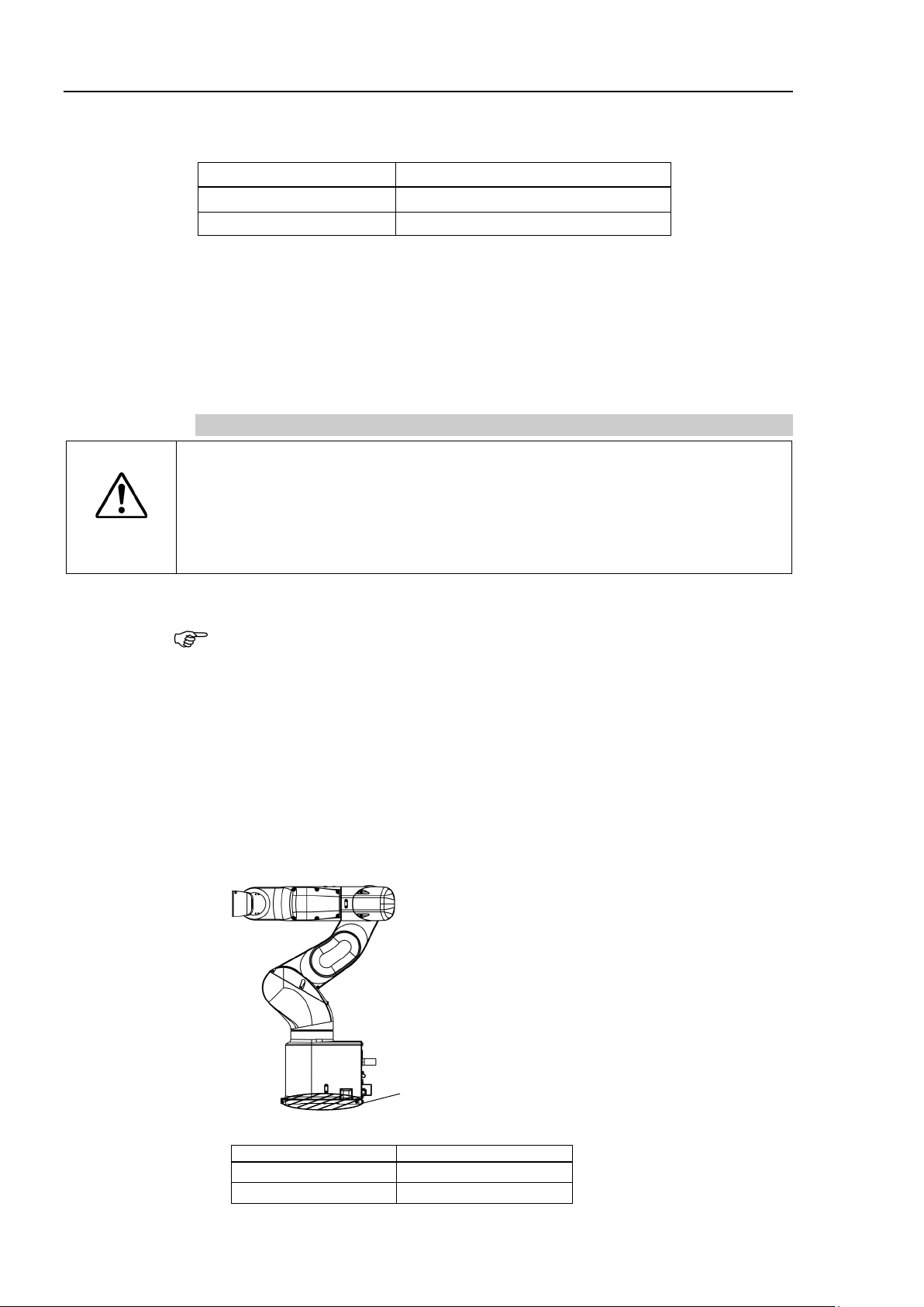
Setup & Operation 3. Environments and Installation
Item
Conditions
Ambient temperature
0 to 45 °C
Ambient relative humidity
10 % to 80 % (no condensation)
Install
m
have
DO NOT hold the bottom of the base by hand.
VT6-A901**
Standard, Cleanroom
Approx. 40 kg: 89 lbs.
Protection
Approx. 42 kg: 92 lbs.
NOTE
Be sure to transport and store the robot system in environments that meet the following
conditions:
During unpacking and relocation, avoid applying external force to the arms and motors of
the Manipulator.
When the Manipulator is used for a robot system again after long-term storage, perform a
test run to verify that it works properly, and then operate it thoroughly.
When condensation occurs on the Manipulator during transport or storage, turn ON the
power only after the condensation dries.
3.8.2 Relocation
CAUTION
■
or relocate the Manipulator with two or more people. The Manipulator
ass are as follows. Be careful not to get hands, fingers, or feet caught and/or
equipment damaged by a fall of the Manipulator.
Standard, Cleanroom: Approx. 40 kg :89 lbs.
Protection: Approx. 42 kg :92 lbs.
(1) Turn OFF the power on all devices.
Remove the mechanical stops if using them to limit the motion range. For details
on the motion range, refer to Setup & Operation: 5.2 Motion Range Setting by
Mechanical Stops.
(2) Unscrew the anchor bolts. Then, remove the Manipulator from the base table.
(3) Position the Manipulator as shown in the figure. Then, secure the Manipulator to
the delivery equipment or have at least 2 people to transport the Manipulator.
Recommend : Joint #2 +55
Joint #3 −55
°
°
Do not hold the bottom of the base (the shaded area in the figure). Holding the area
by hand is extremely hazardous and may cause your hands and fingers to be caught.
40 VT Rev.6
Manipulator mass
Page 57

Setup & Operation 3. Environments and Installation
Holes for eye bolt
2-M8 depth 15
Center of gravity
Center of gravity
VT6-A901**
Standard, Cleanroom
Approx. 40 kg: 89 lbs.
Protection
Approx. 42 kg: 92 lbs.
Remove the eyebolts from the Manipulator after transportation/relocation is
completed.
If the
the eyebolts and it may
Manipulator.
Only authorized personnel
forklift. When
extremely
equipment damage to the robot system.
Using Eyebolt
Check that the eyebolts are securely fastened before transporting the Manipulator.
After transporting the Manipulator, remove the eyebolts and keep them for future use.
The eyebolts and wire must be strong enough to withstand the mass (See the figures below).
If you use the eyebolts to lift up the Manipulator, make sure to put hands on it to keep the
balance. The Manipulator may fall if the balance is lost and this is extremely hazardous.
To prevent damage on the covers and arms, it is recommended to protect the contacting parts
of the wire and arm with a cloth.
Manipulator mass
■
CAUTION
Manipulator is operated with the eyebolts left on it, the arm may collide with
cause equipment damage and/or malfunction of the
THE INSTALLATION SHALL BE PREFORMED BY QUALIFIED INSTALLATION
PERSONNEL AND SHOULD CONFORM TO ALL NATIONAL AND LOCAL CODES
■
should perform sling work and operate a crane and a
these operations are performed by unauthorized personnel, it is
WARNING
VT Re v. 6 41
hazardous and may result in serious bodily injury and/or severe
Page 58

Setup & Operation 3. Environments and Installation
Arm #1
Arm #2
Arm #3, 4
Arm #5, 6*
3.9 Checking the Basic Orientation
After parts have been replaced (motors, reduction gear units, belts, etc.), the Manipulator
cannot operate properly because a gap exists between the origin positions stored in each
motor and these stored in the Controller. The process to compensate the position gap is
called “Calibration”.
At the time of shipment, the basic orientation of the Manipulator shown below is set as the
origin position.
After installing the Manipulator and setup the operating environment, move the Manipulator
to the origin position and check if it moves to the basic orientation properly.
To make the Manipulator move to the origin position, select [Tools]-[Robot Manager] [Control Panel] and click <Home>.
If the gap still exists and the Manipulator cannot be in the basic orientation after the
calibration, please contact the supplier of your region.
3.10 Origin Position Label
12 origin position labels (6 labels + spare) are included in the robot at shipment See the
figures below and attach labels on each axis.
By attaching labels on the arms in basic orientation or any orientation, you can use them as
a mark when the original positions are misaligned.
If origin position is misaligned after replacing motors, reduction gear units, or belts due to
a malfunction, look the origin position labels to align positions roughly.
* Arm #6: There is no space for attaching origin position labels.
Please attach the label on the end effector.
42 VT Rev.6
Page 59

If you use an end effector equipped with a gripper or chuck, connect wires and/or
pneumatic
when the
wires and/or pneuma
as the work piece is released when the Emergency Stop switch is pressed.
I/O
by power disconnection, the
robot system
4. Setting of End Effectors
4.1 Attaching an End Effector
Create an end effector for your Manipulator.
Flange dimensions of the wrist attached to the end of Arm #6 is as below.
■
tubes properly so that the gripper does not release the work piece
power to the robot system is turned OFF. Improper connection of the
tic tubes may damage the robot system and/or work piece
CAUTION
outputs are configured at the factory so that they are automatically shut off (0)
.
Wrist Flange
Setup & Operation 4. Setting of End Effectors
Emergency Stop switch, or the safety features of the
Arm #6
Attach an end effector to the end of the Arm #6 using the M5 bolts.
Layouts
When you operate the Manipulator with an end effector, the end effector may interfere
with the Manipulator body depending on the outer diameter of the end effector, the size
of the work piece, or the position of the arms. When designing your system layout, pay
close attention to the interference area of the end effector.
Compatibility with ISO flange:
To install the end effector whose mounting dimensions are designed for the ISO flange,
we provide the optional “Tool Adapter (ISO flange)”. For details, refer to Setup &
Operation: 11. Options.
VT Rev. 6 43
Page 60

Setup & Operation 4. Setting of End Effectors
Arm #4
Deck
Arm #5
Deck
4.2 Attaching Cameras and Air Valves
Decks are equipped to Arms #4 and #5 to enable the easy installation of air valve.
To mount the camera, the camera plate unit is necessary.
We provide the optional “Camera Plate Unit”. For details, refer to Setup & Operation: 11.
Options.
4.3 Weight and Inertia Settings
The WEIGHT and INERTIA (inertia moment and eccentricity) commands are for setting
the load parameters of the Manipulator. These settings optimize the Manipulator motion.
WEIGHT Setting
The WEIGHT command is for setting the load weight. The more the load weight
increases, the more the speed and acceleration/deceleration are reduced.
44 V T R ev.6
INERTIA Setting
The INERTIA command is for setting the inertia moment and the eccentricity of the load.
The more the inertia moment increases, the more the acceleration and deceleration of the
Arm #6 are reduced. The more the eccentricity increases, the more the acceleration and
deceleration for the Manipulator movement are reduced.
Page 61

Setup & Operation 4. Setting of End Effectors
M (N
I (kgm
m
L
g
m
L
Joint Rotation
Center
To ensure optimum Manipulator performance, make sure that the load (weight of the end
effector and work piece) and inertia moment of the load are within the maximum rating for
the Manipulator, and that Arm #6 does not become eccentric.
If the load or the inertia moment exceeds the ratings or if the load becomes eccentric,
follow the steps in the Setup & Operation 4.3.1 WEIGHT Setting and 4.3.2 INERTIA
Setting, to set parameters.
Setting parameters makes the operation of the Manipulator optimal, reduces vibration to
shorten the operating time, and improves the capacity for larger loads. In addition, it
reduces persistent vibration produced when the inertia moment of the end effector and
work piece is bigger.
The allowable load for VT series Manipulators is 6 kg at the maximum.
Due to the limitations of the moment and inertia moment shown in the table below, the
load (end effector weight + work piece weight) should also meet these conditions.
Allowable Load
Joint Allowable Moment GD2/4 Allowable Moment of Inertia
Joint #4 12.0 N·m (1.22 kgf·m) 0.3 kg·m2
Joint #5 12.0 N·m (1.22 kgf·m) 0.3 kg·m2
Joint #6 7.0 N·m (0.71 kgf·m) 0.1 kg·m2
Moment
The moment indicates amount of torque applied on the joint in order to support the gravity
on the load (end effector + work piece).
The moment increases as weight of the load and amount of eccentricity increase. As this
also increases the load applied on the joint, make sure to keep the moment within the
allowable value.
Inertia moment
The inertia moment indicates how difficult the load (end effector + work piece) to rotate
when the Manipulator joint starts to rotate (amount of inertia). The inertia moment
increases as weight of the load and amount of eccentricity increase. As this also increase
the load applied on the joint, make sure to keep the inertia moment within the allowable
value.
The moment M (Nm) and inertia moment I (kgm
2
) when the volume of the load (end
effector + work piece) is small can be obtained by the following formula.
·m) = m(kg) × L (m) × g (m/s2)
2
) = m(kg) × L2 (m)
: Weight of load (kg)
: Eccentric quantity of load (m)
: Gravitational acceleration (m/s2)
VT Rev. 6 45
Page 62

Setup & Operation 4. Setting of End Effectors
Center of gravity of load from the Arm #5 rotation center [mm]
Center of gravity of load from
the Arm #6 rotation center [mm]
Joint
1 kg
2 kg
3 kg
4 kg
5 kg
6 kg
#4
548 mm
387 mm
316 mm
274 mm
245 mm
204 mm
#5
548 mm
387 mm
316 mm
274 mm
245 mm
204 mm
#6
300 mm
224 mm
183 mm
158 mm
141 mm
119mm
The figure below shows distribution of the center of gravity when the volume of the load
(end effector + work piece) is small.
Design the end effector so that the center of gravity is within the allowable moment.
If the volume of the load is large, calculate the moment and inertia moment by referring to
Setup & Operation 4.3.2 INERTIA setting - Calculating the Inertia Moment.
Max. Eccentric Quantity of Load
(Distance between the joint rotation center and the load’s center of gravity)
When calculating the critical dimension of the load using the allowable moment and
inertia moment, the calculated value represents a distance from the Arm #5 rotation center,
not the distance from the flange. To calculate the distance from the flange to the load’s
center of gravity, subtract the distance from the center of the Arm #5 rotation center to the
flange (=80 mm) as shown in the example below.
46 V T R ev.6
Page 63

Setup & Operation 4. Setting of End Effectors
Arm #J6
Rotation Center
Load’s Center of Gravity
Flange
Arm #J5
Rotation Center
Set the total weight of the end effector and the work piece smaller than the
maximum payload.
The
unless and until the load exceeds this
Weight parameters of the WEIGHT command according to the load. Setting a
value that is smaller than the actual load may cause errors, excessive shock,
insufficient function of the Manipulator, and/or shorten the life cycle
parts/mechanisms.
Rated
Maximum
3 kg
6 kg
EPSON
RC+
Select [Tools]
You may also execute the Weight command from [Command Window].
Example: Calculation of the critical dimension of the load (a) when the load is 6 kg.
Center of gravity by the allowable moment control:
12.0 N·m/(6 kg×9.8 m/s
2
) = 0.204 m = 204 mm
Center of gravity by the allowable inertia moment control:
(0.3 kgm2/6 kg)1/2 = 0.223 m = 223 mm
Due to the allowable moment control, center of gravity for the load limit is 212 mm from
the Arm #5 rotation center.
Distance (a) from the flange to the center of gravity for the load limit
= 204 mm-80 mm = 124 mm
Critical Dimension of Load
CAUTION
[Unit: mm]
4.3.1 Weight Setting
■
VT series Manipulators can operate without limitations on the condition
maximum payload. Always set the
of
The acceptable weight capacity (end effector and work piece) for VT series Manipulators
is as follows:
Change the setting of the Weight parameter according to the load.
After changing the Weight parameter setting, the maximum acceleration/deceleration and
speed of the robot system corresponding to the load is set automatically.
Setting method of Weight parameters
-[Robot Manager]-[Weight] panel and set the value in [Weight:].
VT Rev. 6 47
Page 64

Setup & Operation 4. Setting of End Effectors
Arm #4
Deck
Arm #5
Deck
Load on the fore
end of Arm #6
Load on the Manipulator
Mounting location of the load
When you attach the equipment to the decks on the upper arm, convert its weight into
equivalent weight assuming that the equipment is attached to the end of the Arm #6.
Then, this equivalent weight added to the load will be a Weight parameter.
48 V T R ev.6
Page 65
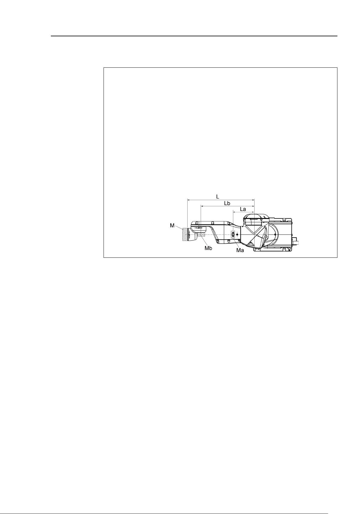
Setup & Operation 4. Setting of End Effectors
Weight parameter =Mw + Wa + Wb
M
W
W
:
:
:
W
W
M
M
L
L
L
:
: Weight of the camera on the Arm #5 deck
: Length of the upper arm (
: Distance between the Joint #3 and the center of gravity of
: Distance between the Joint #3 and the center of gravity
of the camera on the Arm #5 deck (mm)
<
The fore end of the Arm #6 is
of
Load on the fore
Load
The deck is
Load on the Arm #5 deck is
The deck is 390 mm (Lb) away from the Joint #3.
Wa=1.5×1502/4802=0.15 → 0.2 (round up)
W
M
Enter “5.9” for the Weight parameter.
Calculate the Weight parameter by using the formula below and enter the value.
Weight Parameter Formula
Load on the fore end of Arm #6 (kg)
w
Equivalent weight of the Arm #4 deck (kg)
a
Equivalent weight of the Arm #5 deck (kg)
b
2
a=Ma(La
b=Mb(Lb
a
b
a
)2/(L)
)2/(L)2
Weight of the air valve on the Arm #4 deck
480 mm)
the air valve on the Arm #4 deck (mm)
b
Example>
480mm (L) away from the Joint #3
VT6-A901S* (VT6L).
-end of Arm #6 is 5 kg (Mw).
on the Arm #4 deck is 1.5 kg (Ma).
150 mm (La) away from Joint #3.
1.0 kg (Mb).
=1.0×3902/4802=0.66 → 0.7 (round up)
b
+Wa+Wb=5+0.2+0.7=5.9
w
VT Rev. 6 49
Page 66

Setup & Operation 4. Setting of End Effectors
140
120
100
80
60
40
20
0 1 2 3 4 5 6 (kg)
Weight Parameter
(%)
130
100
100
80
60
Speed
Acceleration / Deceleration
130
120
40
100
100
100
100
80
Weight
parameter (kg)
Acceleration /
Deceleration
0
130
100 1 130
100 2 120
100 3 100
100 4 80
100 5 60
100 6 40
80
The
must be
with
Always set the Weight
parameters according to the load. Setting a value that is smaller than the actual
load may cause errors, excessive shock and insufficient function of the
Manipulator.
belt tooth bumping occurs
Automatic speed setting by Weight
The percentages in the graphs are based on the speed at rated weight (3 kg) as 100%.
Speed
4.3.2 INERTIA Setting
Moment of Inertia and the INERTIA Setting
The moment of inertia is defined as “the ratio of the torque applied to a rigid body and its
resistance to motion”. This value is typically referred to as “the moment of inertia”,
“inertia”, or “GD
2
”. When the Manipulator operates with additional objects (such as an
end effector) attached to the shaft, the moment of inertia of load must be considered.
■
moment of inertia of the load (weight of the end effector and work piece)
0.1 kg·m2 or less. The VT series Manipulators are not designed to work
a moment of inertia exceeding 0.1 kg·m2.
CAUTION
Also, the life cycle of parts is shortened and positional gap due to
.
The acceptable inertia moment of load for VT series Manipulators is 0.03 kgm2 nominal
rating and 0.1 kg·m
the inertia moment of the load using the INERTIA command. After the setting has been
changed, the maximum acceleration/deceleration speed of Arm #6 responding to “inertia
moment” is set automatically.
50 V T R ev.6
2
maximum. Change the setting of the inertia moment according to
Page 67
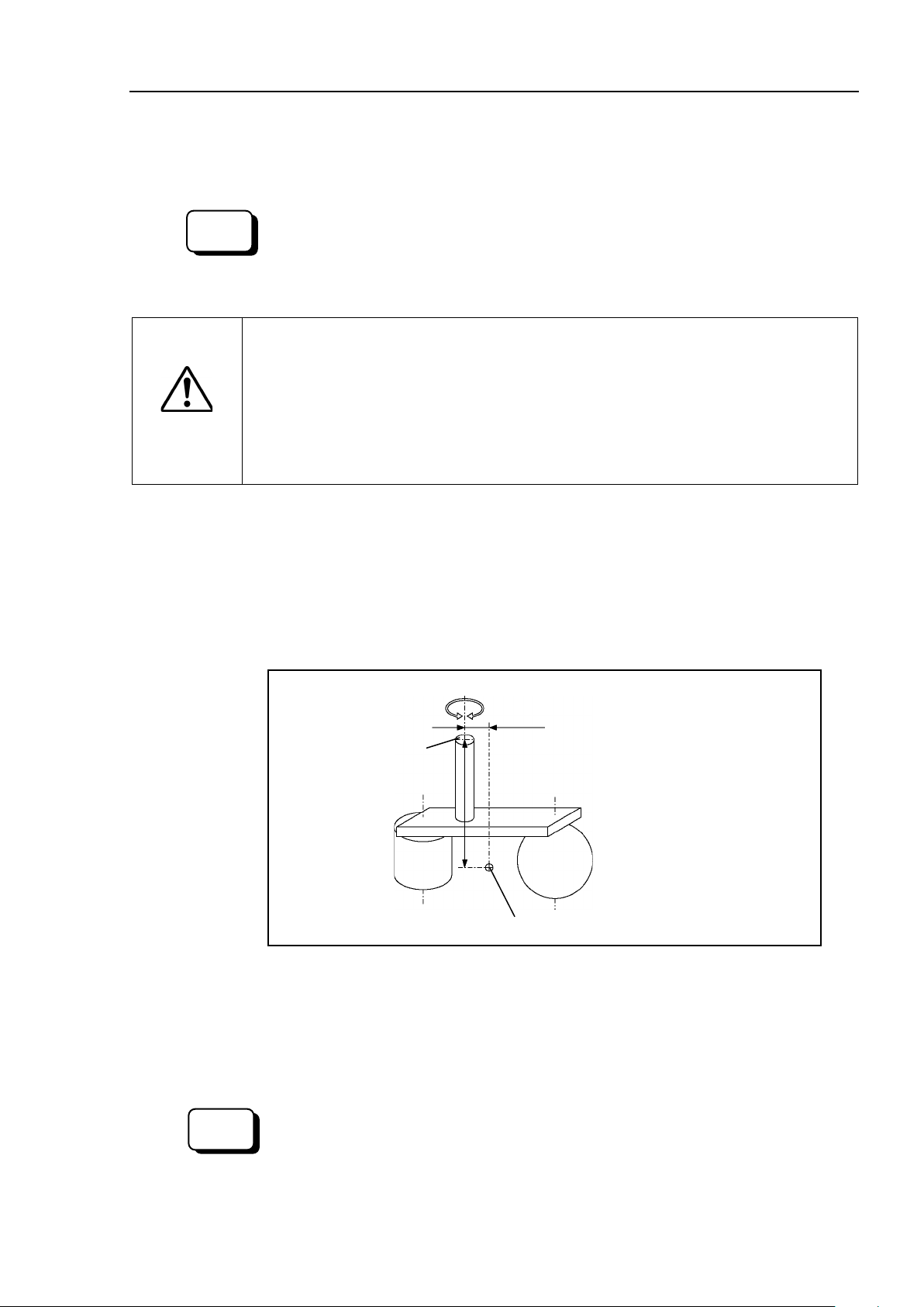
EPSON
RC+
Select [Tools]
You may also execute the Inertia command from [Command Window].
The eccentric quantity of the load (weight of the end effector and work piece)
must be
with eccentric quantity exceeding
Always set the eccentric quantity parameter according to the eccentric quantity.
Setting a value that is smaller than the actual eccentric quantity may cause
errors, excessive shock, insufficient function of the Manipulator, and/or shorten
the life cycle of parts/mechanisms.
Position of Load’s Center of Gravity
Rotation Center
a, b = Eccentric Quantity
(300 mm or less)
Flange
a
b
To set the parameter, enter
the larger value of “a” or “b”.
EPSON
RC+
Select
You may also execute the Inertia command from [Command Window].
CAUTION
Setup & Operation 4. Setting of End Effectors
Inertia moment of load on Arm #6
The inertia moment of the load (weight of the end effector and work piece) on the Arm #6
can be set by the “inertia moment (INERTIA)” parameter of the INERTIA command.
–[Robot Manager]-[Inertia] panel and enter the value in [Load inertia:].
Eccentric Quantity and the INERTIA Setting
■
300 mm or less. The VT series Manipulators are not designed to work
300 mm.
The acceptable eccentric quantity of the load for VT series Manipulators is 50 mm at
nominal rating and 300 mm at maximum.
When the eccentric quantity of the load exceeds the rating, change the setting of eccentric
quantity parameter using the INERTIA command. After changing the setting, the
maximum acceleration/deceleration speed of Manipulator corresponding to “eccentric
quantity” is set automatically.
Eccentric Quantity
Eccentric quantity of load on Arm #6
The eccentric quantity of the load (weight of the end effector and work piece) on the Arm
#6 can be set by the “eccentric quantity” parameter of the INERTIA command.
Enter the larger value of either “a” or “b” in the figure above to [Eccentricity].
[Tools]–[Robot Manager]-[Inertia] panel and enter the value into [Eccentricity:].
VT Rev. 6 51
Page 68
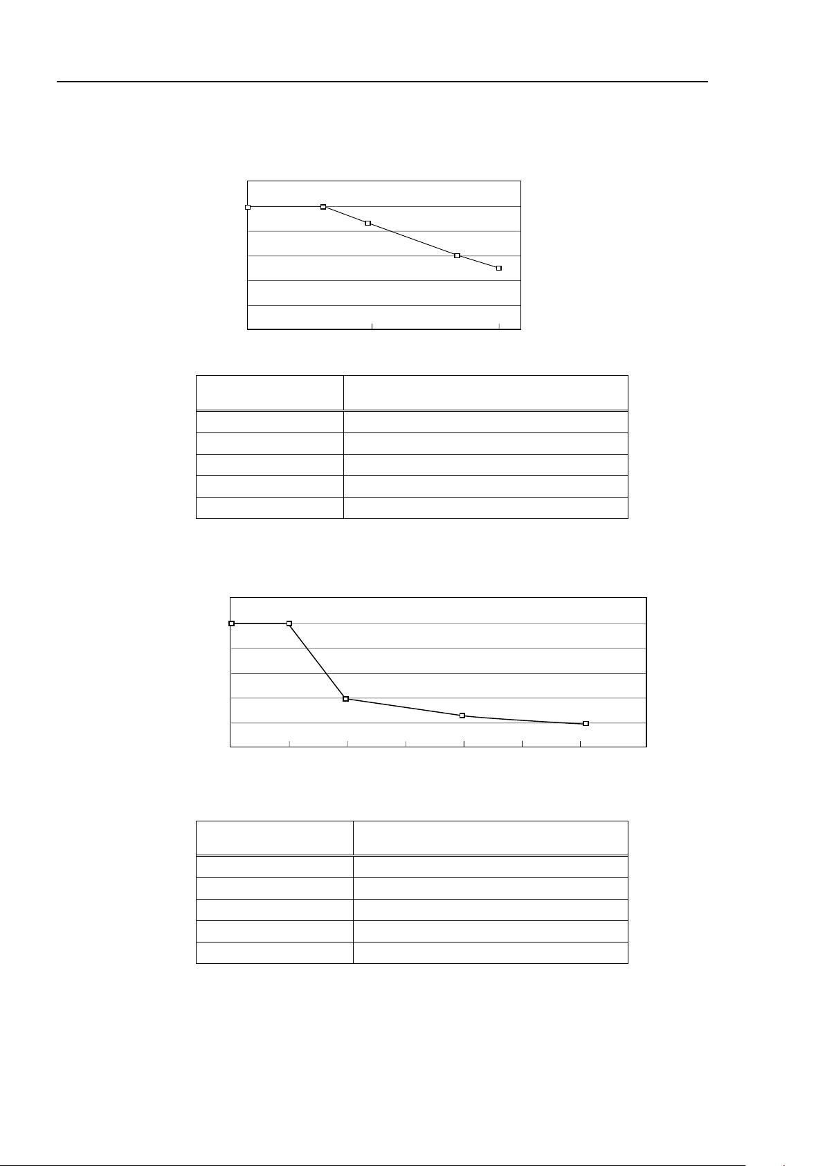
Setup & Operation 4. Setting of End Effectors
0 0.05 0.10 (kg·m2)
Inertia moment
120
100
80
60
40
20
(%)
100
85
60
50
100
Moment of inertia
setting (kg·m2)
Automatic acceleration/deceleration
setting by Inertia (moment of inertia) (%)
0
100
0.03
100
0.05
85
0.08
60
0.1
50
120
100
80
60
40
20
0 50 100 150 200 250 3
00
350 (mm)
100
40
(%)
100
25
20
Eccentricity setting
Eccentric quantity
parameter (mm)
Automatic acceleration/deceleration
setting by Inertia (eccentric quantity) (%)
0
100
50
100
100
40
200
25
300
20
Automatic acceleration/deceleration setting by INERTIA (eccentric quantity)
The percentage in the graph is based on the acceleration/ deceleration at rated eccentricity
(0.03 kg·m2) as 100%.
Automatic setting by eccentricity setting
The percentage in the graph is based on the acceleration/ deceleration at rated eccentricity
(50 mm) as 100%
52 V T R ev.6
Page 69

Setup & Operation 4. Setting of End Effectors
Work Piece (b)
Work Piece (c)
End Effector (a)
Rotation Center
Moment of Inertia
of End Effector (a)
=
Moment of Inertia
of Work Piece (b)
+
Moment of Inertia
of Work Piece (c)
+
Whole Moment
of Inertia
h
b
L
Weight = m
Rectangular Parallelepiped’s Center of Gravity
Rotation Center
m
+ m × L2
b2 + h2
12
m
+ m × L2
r 2
2
Weight = m
L
r
Cylinder’s Center of Gravity
Rotation Center
Calculating the Inertia Moment
Refer to the following example formulas to calculate the inertia moment of the load (end
effector with work piece).
The inertia moment of the entire load is calculated by the sum of (a), (b), and (c).
The methods for calculating the inertia moment for (a), (b), and (c) are shown in this and
the next page. Figure out the whole inertia moment using the basic formulas below.
(a) Inertia moment of a rectangular parallelepiped
(b) Inertia moment of a cylinder
VT Rev. 6 53
Page 70
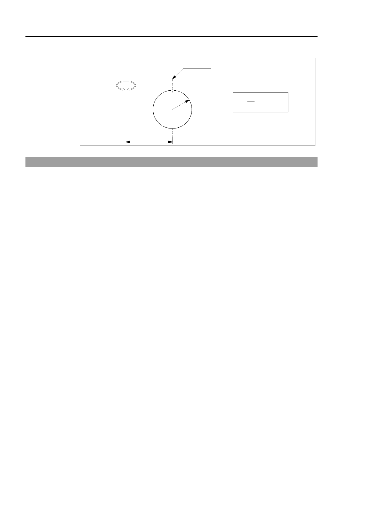
Setup & Operation 4. Setting of End Effectors
m
r 2+ m × L2
2
5
Sphere’s Center of Gravity
r
Weight = m
L
Rotation Center
(c) Inertia moment of a sphere
4.4 Precautions for Auto Acceleration/Deceleration of Joint #3
The speed and acceleration/deceleration of the Manipulator motion are automatically
optimized according to the values of WEIGHT and INERTIA and the Manipulator’s
postures.
WEIGHT Setting
The speed and acceleration/deceleration of the Manipulator are controlled according to the
load weight set by the WEIGHT command.
The more the load weight increases, the more the speed and acceleration/deceleration are
reduced to prevent residual vibration.
INERTIA Setting
The acceleration/deceleration of Arm #6 are controlled according to the inertia moment set
by the INERTIA command. The acceleration/deceleration of the whole Manipulator are
controlled according to the eccentricity set by the INERTIA command. The more the
inertia moment and eccentricity of the load increase, the more the acceleration/
deceleration are reduced.
Auto Acceleration/Deceleration According to Manipulator’s Posture
The acceleration/deceleration are controlled according to the Manipulator’s posture.
When the Manipulator extends its arms or when the movement of the Manipulator
produces vibration frequently, the acceleration/deceleration are reduced.
Set appropriate values for WEIGHT and INERTIA so that the Manipulator operation is
optimized.
54 V T R ev.6
Page 71

When setting up the motion range for safety, both the pulse range and
mechanical stops must always be set
cause serious safety problems.
Mechanical
stop
Rectangular range setting
Pulse range
Motion range
Mechanical
stop
EPSON
RC+
The pulse range can be set in [Tools]
You may
NOTE
NOTE
5. Motion Range
■
CAUTION
The motion range is preset at the factory as explained in Setup & Operation: 2.5 Standard
Motion Range. That is the maximum motion range of the Manipulator.
There are three methods for setting the motion range described as follows:
1. Setting by pulse range (for all joints)
2. Setting by mechanical stops
3. Setting the Cartesian (rectangular) range in the X, Y coordinate system of the
Setup & Operation 5. Motion Range
at the same time. Failure to do so may
Manipulator
When the motion range is changed due to layout efficiency or safety, follow the
descriptions in 5.1 to 5.3 to set the range.
5.1 Motion Range Setting by Pulse Range (for All Joints)
Pulses are the basic unit of Manipulator motion. The motion range of the Manipulator is
controlled by the pulse range (the lower limit and the upper limit) of each axis.
Pulse values are read from the encoder output of the servo motor.
The pulse range should be set within the mechanical stop range.
The Arms #4 and #6 do not have a mechanical stop.
Once the Manipulator receives an operating command, it checks whether the target
position specified by the command is within the pulse range before operating. If the
target position is out of the set pulse range, an error occurs and the Manipulator does not
move.
-[Robot manager]-[Range] panel.
also execute the Range command from the [Command Window].
VT Rev. 6 55
Page 72
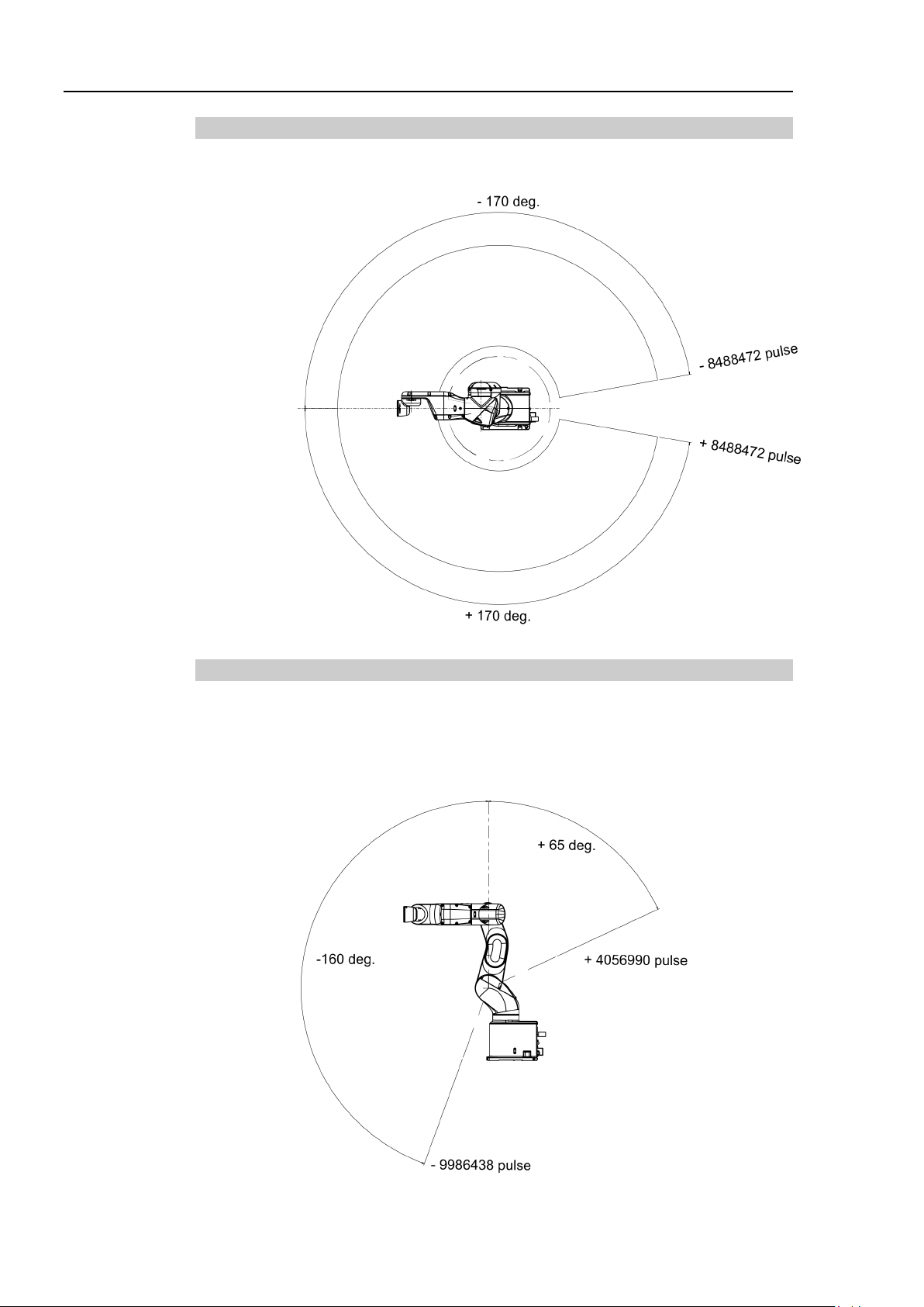
Setup & Operation 5. Motion Range
Arm #1
0 pulse position
Arm #2
0 pulse position
5.1.1 Max. Pulse Range of Joint #1
Pulse values in counterclockwise direction are positive (+) and values in clockwise
direction are negative (-).
5.1.2 Max. Pulse Range of Joint #2
Pulse values in clockwise direction are positive (+) and values in counterclockwise
direction are negative (-).
56 V T R ev.6
Page 73

Setup & Operation 5. Motion Range
Arm #3
0 pulse position
+ 8816759 pulse
- 2366604 pulse
Arm #4
0 pulse position
- 8128764 pulse
+ 8128764 pulse
Arm #5
0 pulse position
5.1.3 Max. Pulse Range of Joint #3
Pulse values in clockwise direction are positive (+) and values in counterclockwise
direction are negative (-).
5.1.4 Max. Pulse Range of Joint #4
From the angle of arm end, clockwise pulse values are positive (+) and counterclockwise
pulse values are negative (-).
5.1.5 Max. Pulse Range of Joint #5
Pulse values in clockwise direction are positive (+) and values in counterclockwise
direction are negative (-).
VT Rev. 6 57
Page 74

Setup & Operation 5. Motion Range
Arm #6
0 pulse position
5.1.6 Max. Pulse Range of Joint #6
From the angle of arm end, clockwise pulse values are positive (+) and counterclockwise
pulse values are negative (-).
58 V T R ev.6
Page 75

a
b
−170 to +84
or −84 to +170
− 8488472 to +4194304,
or − 4194304 to +8488472
Adjustable mechanical stop
(J1)
Not applied
(standard)
5.2 Motion Range Setting by Mechanical Stops
Using the adjustable mechanical stops (option) physically limits the absolute area that the
Manipulator can move.
Be sure to turn OFF the Manipulator in advance.
Setup & Operation 5. Motion Range
Use bolts conforming to the specified length and surface processing (ex:
nickel plating)
with high corrosion resistance.
Specify the pulse range again after changing the position of the mechanical stop.
For details on the pulse range setting, refer to the the following section.
Setup & Operation 5.1 Motion Range Setting by Pulse Range (for All Arms).
Be sure to set the pulse range not to exceed the setting angles of the mechanical stop.
5.2.1 Motion Range Setting of Joint #1
Install the adjustable mechanical stop (J1) to the threaded hole corresponding to the angle
you want to set.)
Hexagon socket head cap bolt M4 × 28 (1 bolt)
Tightening torque 4.0 ± 0.2 N·m (41 ± 2 kgf·cm)
Angle (°) ±170
Pulse (pulse)
±8488472
Applied
VT Rev. 6 59
Page 76

Setup & Operation 5. Motion Range
c
d
−160 to +43,
or −148 to +65
−9986438
+4056990
−9986438 to +2683855,
or −9237455 to +4056990
Adjustable mechanical stop
(J2)
Not applied
(standard)
5.2.2 Motion Range Setting of Joint #2
Install the adjustable mechanical stop (J2) to the threaded hole corresponding to the angle
you want to set.)
Hexagon socket head cap bolt M4 × 16 (1 bolt)
Tightening torque 4.0 ± 0.2 N·m (41 ± 2 kgf·cm)
Angle (°) −160, +65
Pulse (pulse)
Applied
60 V T R ev.6
Page 77

Setup & Operation 5. Motion Range
e
f
−34 to +190,
or −51 to +173
2366604
+8816759
−1577736 to +8816759
or −2366604 to +8027891
Adjustable mechanical stop
(J3)
Not applied
(standard)
5.2.3 Motion Range Setting of Joint #3
Install the adjustable mechanical stop (J3) to the threaded hole corresponding to the angle
you want to set.)
Hexagon socket head cap bolt M4 × 16 (1 bolt)
Tightening torque 4.0 ± 0.2N·m (41 ± 2 kgf·cm)
Angle (°) −51, +190
Pulse (pulse)
−
Applied
VT Rev. 6 61
Page 78

Setup & Operation 5. Motion Range
Joint #2 Angle
Joint #3 Angle
Joint #2 Angle
Joint #3 Angle
5.3 Restriction of Manipulator Operation by Joint Angle Combination
To prevent the arms of the Manipulator from interfering each other, the Manipulator
operation is restricted in the specified motion range according to the joint angle
combination of the Joints #1, #2, and #3.
The Manipulator operation is restricted and the Manipulator stops when the joint angles of
the Arm are within the colored areas in the following figures. In addition, the
determination whether inside and outside of the colored area may differ depending on a
position due to calculation error on the boundary line between the colored area and the
white area as shown below.
The restriction to Manipulator operation is enabled:
- During CP motion command execution
- When you attempt to execute the motion command for moving the Manipulator to a
target point (or pose) in the specified motion range.
The restriction to the Manipulator operation is disabled:
- The Arms of the Manipulator momentarily go through the specified motion range
during the PTP motion command execution even though the joint angles of the Arms
are in the colored area of the figures above.
Combination of Joint #2 and #3
Joint#1: −110 deg. to 110 deg.
Joint#1: −110 deg. to −170 deg. or 110 deg. to 170 deg.
(deg.= °)
62 V T R ev.6
Page 79

Table Top mounting
Ceiling mounting*
Wall mounting*
+Z
+X
+Y
+Z
+X
+Y
+X
+Y
+Z
+X
+X
+Y
+Y
5.4 Coordinate System
The origin point is where the Manipulator’s installation face intersects with the rotation
axis of Joint #1.
For details on the coordinate system, refer to the EPSON RC+ User’s Guide manual.
Setup & Operation 5. Motion Range
*: Only for Standard model
VT Rev. 6 63
Page 80
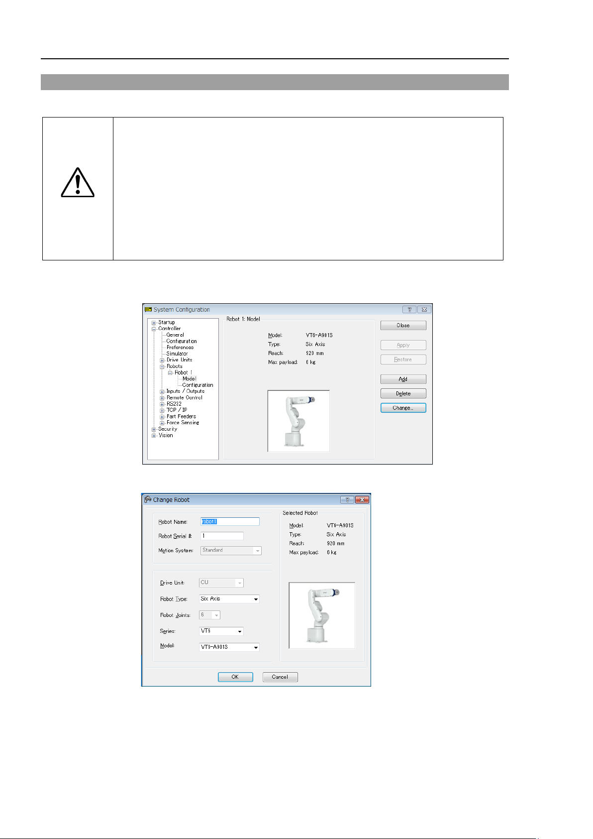
Setup & Operation 5. Motion Range
calibration parameters (Hofs, CalPls), additional axis information, and PG parameter
Before changing the robot, make sure to save the calibration data by following the
[Calibration] from the tree list. Then, click
5.5 Changing the Robot
This section describes how to change the Manipulator model on EPSON RC+.
■
Changing the Manipulator should be done with great caution. It initializes the robot
data.
CAUTION
procedure below.
(1) Select the EPSON RC+ 7.0 menu-[Setup]-[System Configuration].
(2) Select [Robot]-[Robot**]-
<Save>.
(1) Select the EPSON RC+ 7.0 menu-[Setup]-[System Configuration].
(2) Select [Robot]-[Robot**] from the tree list.
(3) Click the <Change…> button. The following dialog box will be displayed.
(4) Input the robot name and serial number printed on the name plate of the manipulator.
Any serial number can be entered. However, enter the number printed on the
manipulator.
(5) Select the robot type in the [Robot Type] box.
(6) Select the series name of the manipulator in the [Series] box.
64 V T R ev.6
Page 81

Setup & Operation 5. Motion Range
EPSON
RC+
Set the XYLIM setting in [Tools]
You may also execute the XYLim co
(7) Select the robot model in the [Model] box. Available robots will be displayed
according to the format of the currently installed motor driver. When [Dry run] is
used, all the Manipulators of the series selected in Step 6 will be displayed.
(8) Click the <OK> button. The Controller will be restarted.
5.6 Setting the Cartesian (Rectangular) Range in the XY Coordinate
System of the Manipulator
The Cartesian (rectangular) range in the XY coordinate system of the Manipulator is
specified by the limited Manipulator operation area and the XYLIM setting.
The limited Manipulator operation area is defined so that the end effector does not
interfere with the rear side of the Manipulator. The XYLIM setting that you can
determines the upper and lower limits of the X and Y coordinates.
The limited Manipulator operation area and the XYLIM setting apply only to the software.
Therefore, these settings do not change the physical range. The maximum physical range
is based on the position of the mechanical stops.
These settings are disabled during a joint jogging operation. Therefore, be careful not to
allow the end effector to collide with the Manipulator or peripheral equipment.
-[Robot manager]-[XYZ Limits] panel.
mmand from the [Command Window].
VT Rev. 6 65
Page 82

Setup & Operation 6. Operation Mode & LED
This is a low speed program verification function (T1: manual
6. Operation Mode & LED
6.1 Overview
The Robot system has three operation modes.
TEACH mode This mode enables point data teaching and checking close to the
Manipulator using the Teach Pendant.
In this mode the Manipulator operates in Low power status.
AUTO mode This mode enables automatic operation (program execution) of the
Robot system for the manufacturing operation, and also
programming, debug, adjustment, and maintenance of the Robot
system.
This mode cannot operate the Manipulators or run programs with the
Safety Door open.
TEST mode
This mode enables program verification while the Enable Switch is
held down and the safeguard is open.
deceleration mode) which is defined in Safety Standards.
This mode can operate the specified Function with multi-task /
single-task, multi-
6.2 Switch Operation Mode
Change the operation mode using the mode selector key switch on the Teach Pendant.
TEACH mode Turn the mode selector key switch to “Teach” for TEACH mode.
Switching to TEACH mode pauses the program if it was running.
The operating Manipulator stops by Quick Pause.
AUTO mode Turn the mode selector key switch to “Auto” and turn ON the latch
release input signal for AUTO mode.
TEST mode Turn the mode selector key switch to “Teach” for “TEACH” mode.
Push <F1> key-[Test Mode] in [Jog & Teach] dialog box of TEACH
mode. The mode will be changed to TEST
Manipulator / single-Manipulator at low speed.
66 V T R ev.6
Page 83
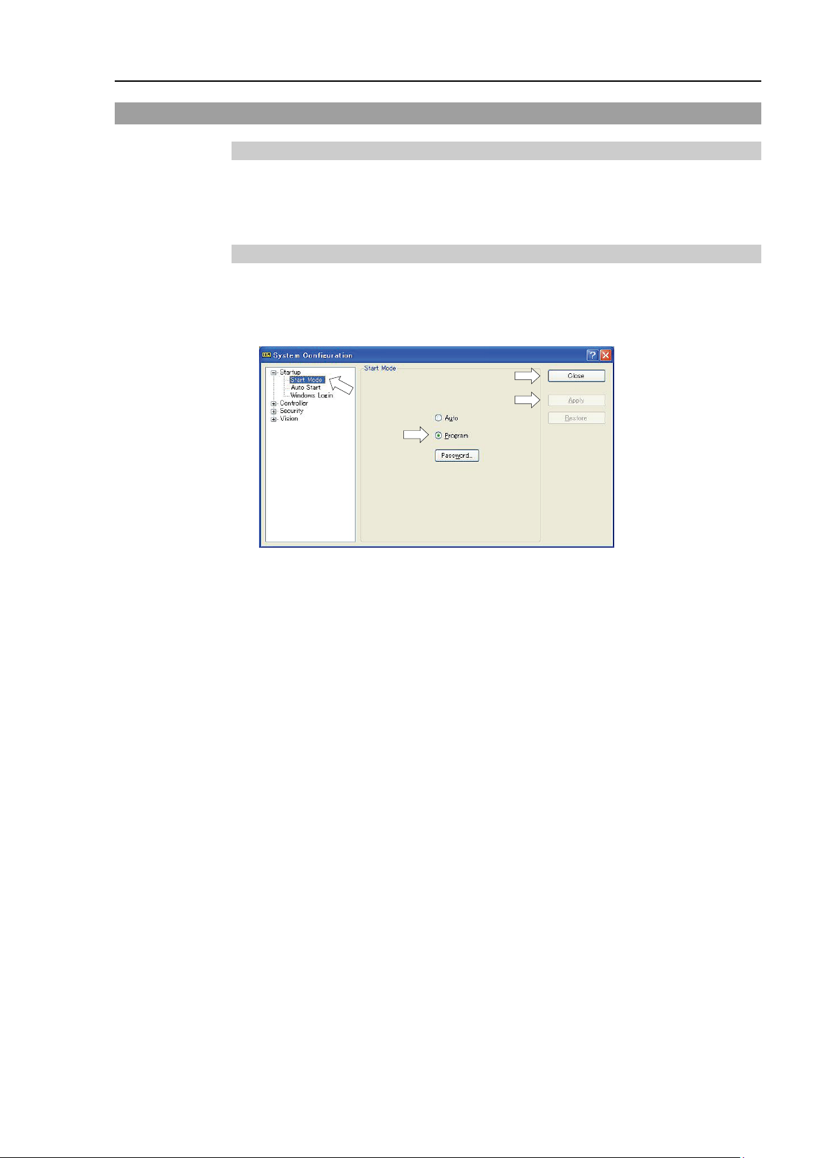
(2)
(5)
(3)
(4)
6.3 Program Mode (AUTO)
6.3.1 What is Program Mode (AUTO)?
Program mode is for programming, debug, adjustment, and maintenance of the Robot
system.
Follow the procedures below to switch to the Program mode.
6.3.2 Setup from EPSON RC+ 7.0
Switch the mode to Program mode from the EPSON RC+ 7.0.
(1) Select EPSON RC+ 7.0 menu-[Setup]-[System Configuration] to display the [System
Configuration] dialog box.
Setup & Operation 6. Operation Mode & LED
(2) Select [Startup].
(3) Select [Start mode]-<Program> button.
(4) Click the <Apply> button.
(5) Click the <Close> button.
VT Rev. 6 67
Page 84
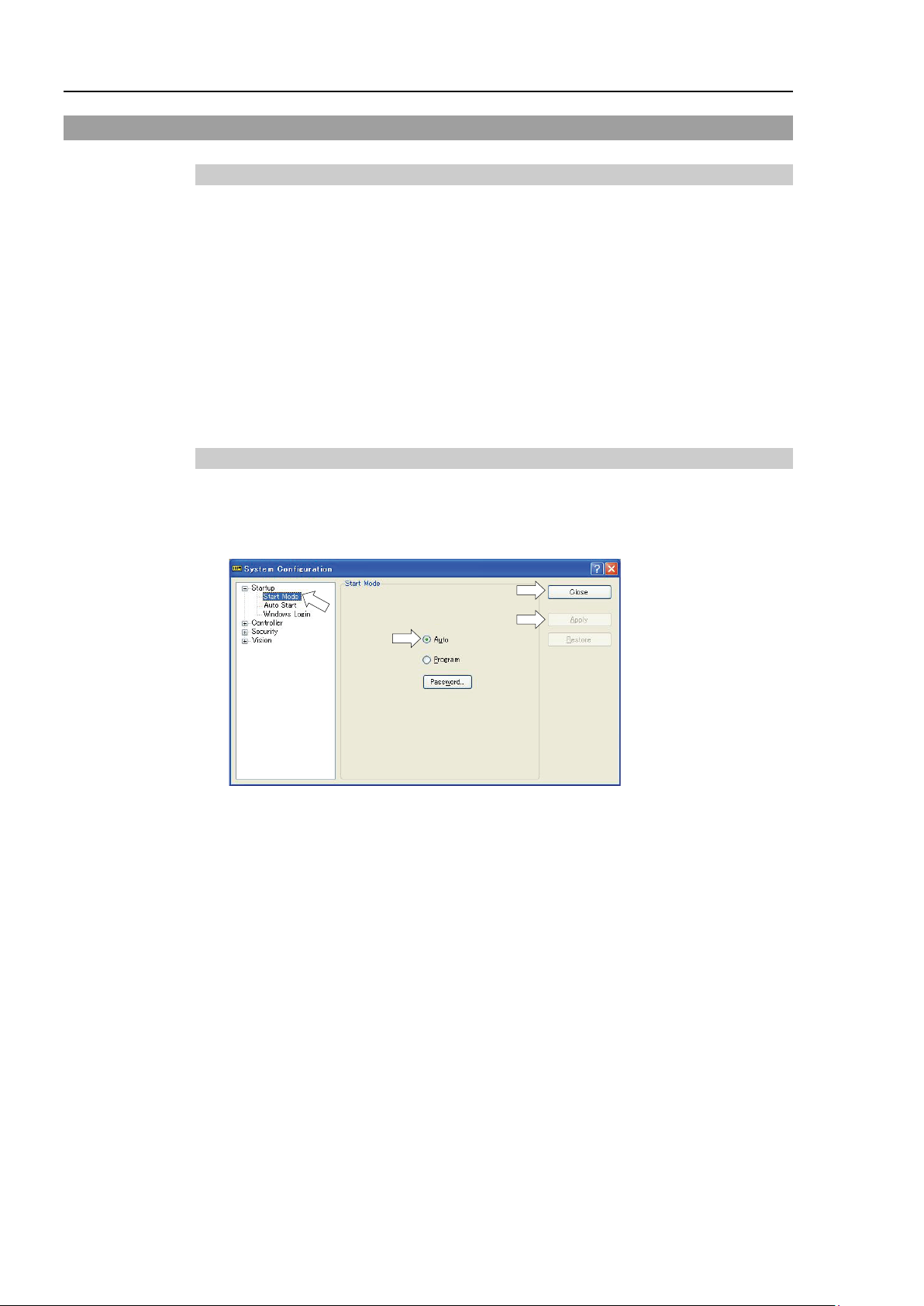
Setup & Operation 6. Operation Mode & LED
(2)
(5)
(3)
(4)
NOTE
6.4 Auto Mode (AUTO)
6.4.1 What is Auto mode (AUTO)?
Auto mode (AUTO) is for automatic operation of the Robot system.
Procedures for switching to the Auto mode (AUTO) are the following.
A : Set the start mode of the EPSON RC+ 7.0 to “Auto” and start the EPSON RC+
7.0.
(Refer to Setup & Operation 6.3.2 Setup from EPSON RC+ 7.0.)
B : Offline the EPSON RC+ 7.0.
Execute and stop the program from the control device specified by the EPSON RC+ 7.0.
(Refer to Setup & Operation 6.4.3 Setup Control Device.)
6.4.2 Setup from EPSON RC+ 7.0
Switch the mode to Auto mode (AUTO) from the EPSON RC+ 7.0.
(1) Select EPSON RC+ 7.0 menu-[Setup]-[System Configuration] to display the [System
Configuration] dialog box.
(2) Select [Startup].
(3) Select [Start Mode]-<Auto> button.
(4) Click the <Apply> button.
(5) Click the <Close> button.
68 V T R ev.6
Page 85
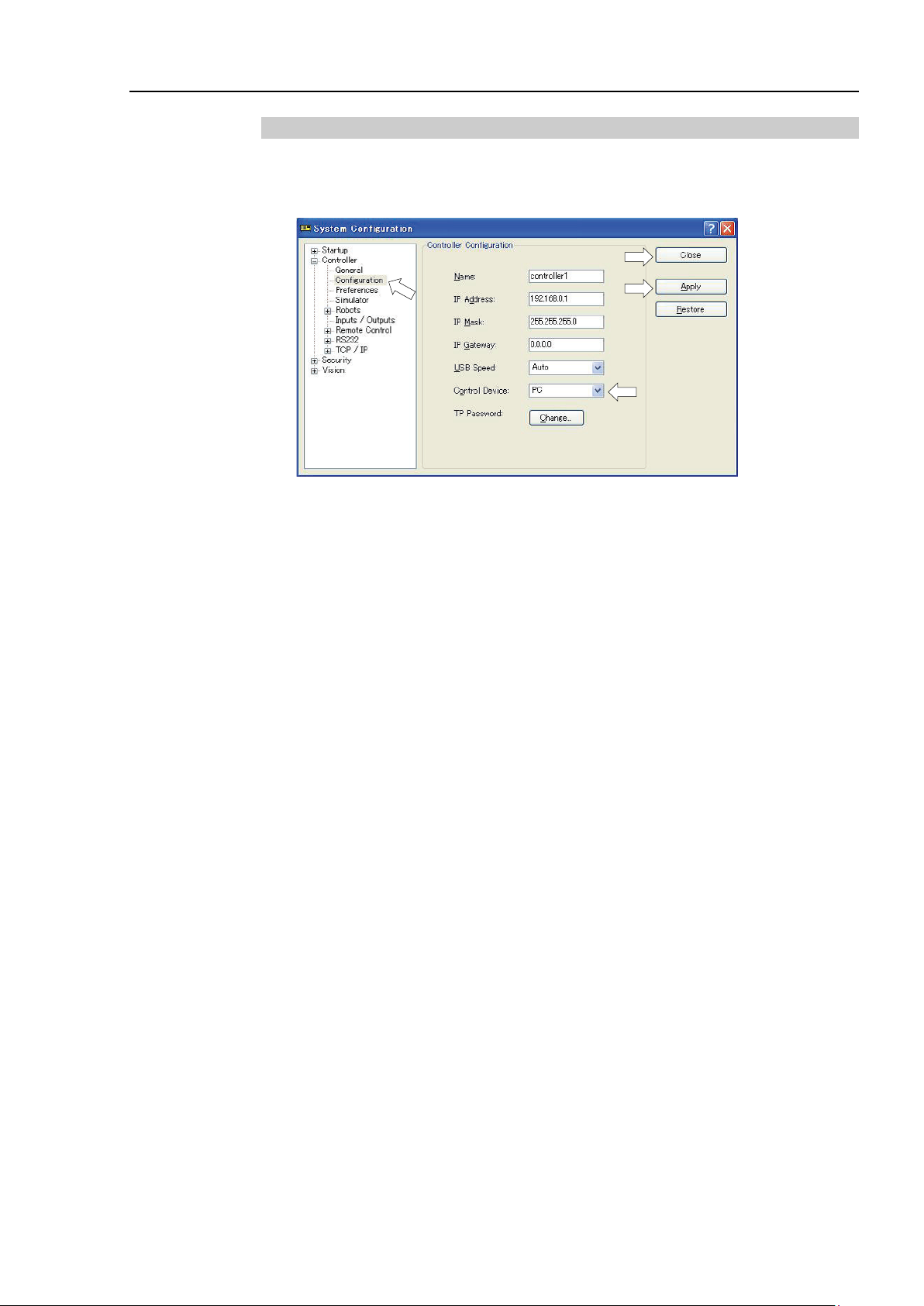
Setup & Operation 6. Operation Mode & LED
(2)
(5)
(3)
(4)
6.4.3 Setup from Control Device
Set the control device from EPSON RC+ 7.0.
(1) Select EPSON RC+ 7.0 menu-[Setup]-[System Configuration] to display the [System
Configuration] dialog box.
(2) Select [Controller]-[Configuration].
(3) Select [Control Device] to select the control device from the following two types.
- PC
- Remote (I/O)
(4) Click the <Apply> button.
(5) Click the <Close> button.
VT Rev. 6 69
Page 86

Setup & Operation 6. Operation Mode & LED
Controller status
LED display
5. Either of TEACH, AUTO, or PROGRAM turns ON
USB memory
ERROR turns OFF even if an error occurs.
storage to USB memory
(for 2 seconds).
6.5 LED
Six LEDs are located on the front panel of the Manipulator.
LEDs (ERROR, E-STOP, TEACH, T ES T, AUTO, PROGRAM) turn ON according to the
Controller status (error, Emergency Stop, TEACH mode, Auto mode, Program mode).
Standard, Cleanroom model Protection model
1. TEST, TEACH, AUTO, and PROGRAM blink
Start up
(Required time is different
depending on the connection
status of the device.)
Execute Controller status
storage function to the
Complete Controller status
storage to USB memory
Failure of Controller status
Error ERROR turns ON
(for 15 seconds)
2. All turn OFF (10 seconds)
3. All turn ON (to 10 seconds )
4. All turn OFF (10-30 seconds )
TEACH, AUTO, PROGRAM blink.
TEACH, AUTO, PROGRAM turn ON
(for 2 seconds).
ERROR, TEACH, AUTO, PROGRAM turn ON
Warning ERROR blinks.
Emergency Stop
TEACH mode TEACH blinks.
Auto mode (AUTO mode) AUTO blinks.
70 V T R ev.6
Program mode (AUTO mode) PROGRAM blinks.
AC power supply drop TEACH, AUTO turn ON.
TEST mode TEST blinks.
E-STOP turns ON.
Page 87
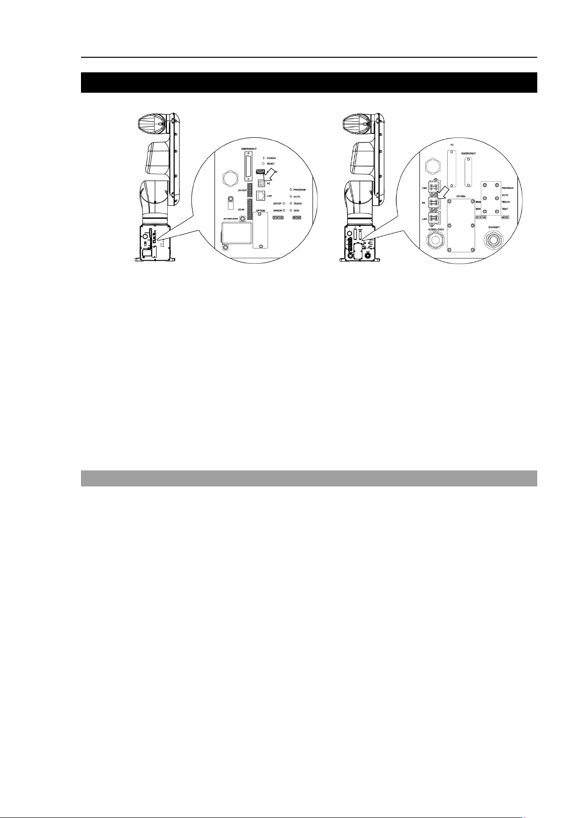
Setup & Operation 7. Development PC Connection Port
NOTE
7. Development PC Connection Port
Standard, Cleanroom model Protection model
- For other details of development PC and Manipulator connection, refer to the following
manual.
EPSON RC+ 7.0 User’s Guide
5.12.1 PC to Controller Communications Command.
- Be sure to install the EPSON RC+ 7.0 to the development PC first, then connect the
development PC and Manipulator with the USB cable.
If Manipulator and the development PC are connected without installing the EPSON
RC+ 7.0 to the development PC, [Add New Hardware Wizard] appears. If this wizard
appears, click the <Cancel> button.
7.1 What is Development PC Connection Port
The development PC connection port supports the following USB types.
- USB2.0 HighSpeed/FullSpeed (Speed auto selection, or FullSpeed mode)
- USB1.1 FullSpeed
Interface Standard : USB specification Ver.2.0 compliant
(USB Ver.1.1 upward compatible)
Connect the Manipulator and development PC by a USB cable to develop the robot system
or set the Manipulator configuration with the EPSON RC+ 7.0 software installed in the
VT Rev. 6 71
development PC.
Development PC connection port supports hot plug feature. Cables insert and remove
from the development PC and the Manipulator are available when the power is ON.
However, stop occurs when USB cable is removed from the Manipulator or the
development PC during connection.
Page 88
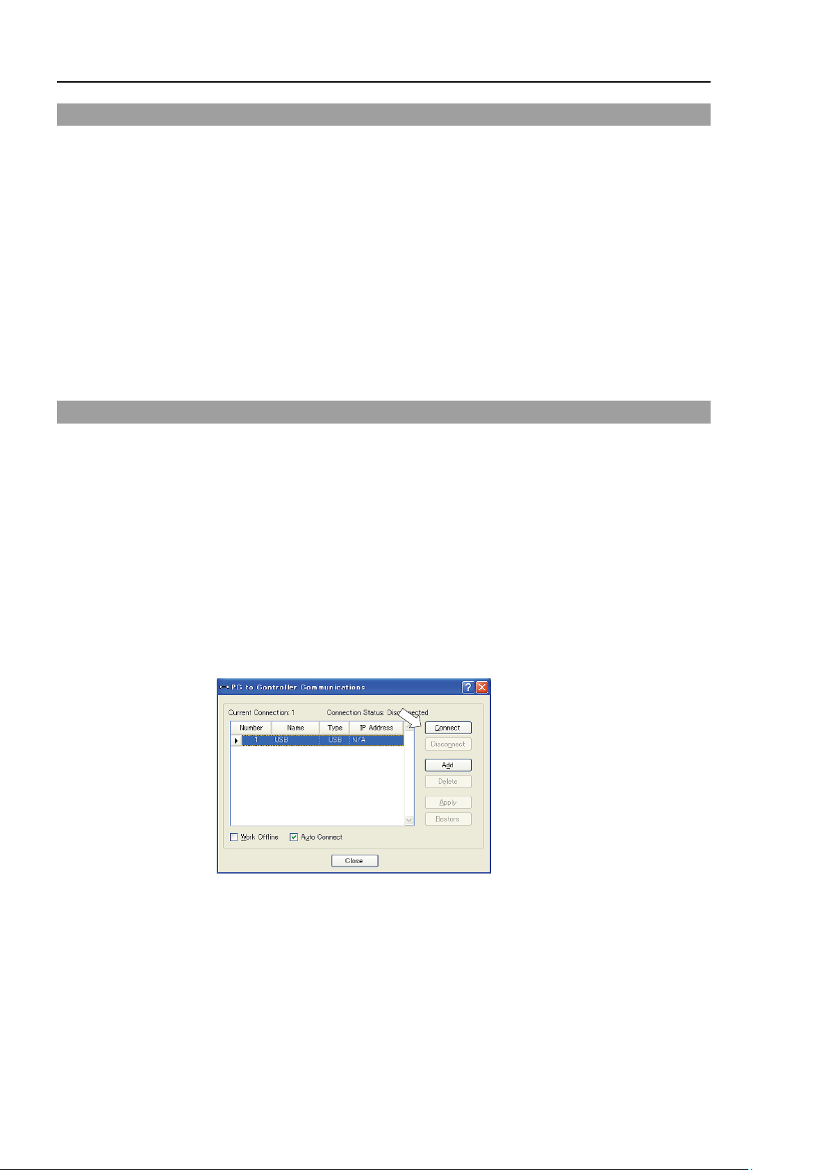
Setup & Operation 7. Development PC Connection Port
7.2 Precaution
When connecting the development PC and the Manipulator, make sure of the following:
- Connect the development PC and the Manipulator with a 5 m or less USB cable.
Do not use the USB hub or extension cable.
- Make sure that no other devices except the development PC are used for development
PC connection port.
- Use a PC and USB cable that supports USB2.0 HighSpeed mode to operate in
USB2.0 HighSpeed mode.
- Do not pull or bend the cable strongly.
- Do not allow unnecessary strain on the cable.
- When the development PC and the Manipulator are connected, do not insert or
remove other USB devices from the development PC. Connection with the
Manipulator may be lost.
7.3 Software Setup and Connection Check
Connection of the development PC and the Manipulator is indicated.
(1) Make sure that software EPSON RC+ 7.0 is installed to the Manipulator connected
to the development PC.
(Install the software when it is not installed. Refer to Robot System Safety and
Installation or EPSON RC+ 7.0 User’s Guide.
(2) Connect the development PC and the Manipulator using a USB cable.
(3) Turn ON the Manipulator.
(4) Start EPSON RC+ 7.0.
(5) Select the EPSON RC+ 7.0 menu-[Setup]-[PC to Controller Communications] to
display the [PC to Controller Communications] dialog box.
(6) Select “No.1 USB” and click the <Connect> button.
72 V T R ev.6
Page 89
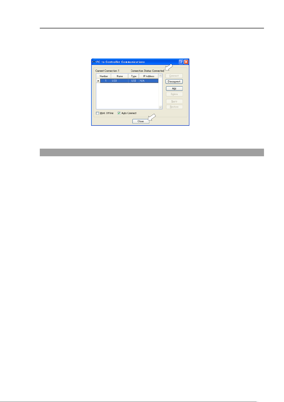
Setup & Operation 7. Development PC Connection Port
(7) After the development PC and the Manipulator connection has completed, “Connected”
is displayed at [Connection status]. Make sure that “Connected” is displayed and
click the <Close> button to close the [PC to Controller Communications] dialog box.
The connection between the development PC and the Manipulator is completed. Now
the robot system can be used from EPSON RC+ 7.0.
7.4 Disconnection of Development PC and Manipulator
Disconnection of the development PC and the Manipulator communication.
(1) Select the EPSON RC+ 7.0 menu-[Setup]-[PC to Controller Communications] to
display the [PC to Controller Communications] dialog box.
(2) Click the <Disconnect> button.
Communication between the Manipulator and the development PC is disconnected
and the USB cable can be removed.
If the USB cable is removed when the Manipulator and the development PC are connected,
the Manipulator will stop. Be sure to click the <Disconnect> button in the [PC to
Controller Communications] dialog box before USB cable is removed.
VT Rev. 6 73
Page 90

Setup & Operation 8. Memory Port
Controller status storage function is available at any time and in any Manipulator
status after starting the Manipulator.
However, operations form the console including stop and pause are not available
while executing this function.
Also,
with EPSON RC+ 7.0. Other than only when it is necessary, do not execute this
function when operating the Manipulator.
8. Memory Port
Connect a commercial USB memory to the Manipulator memory port to use the Controller
status storage function to the USB memory.
Standard, Cleanroom model Protection model
8.1 What is Controller Status Storage Function?
This function saves various kinds of Manipulator data to the USB memory. Data saved
in USB memory is loaded to EPSON RC+ 7.0 to get the status of the Manipulator and the
program simply and accurately.
The saved data can also be used for restoring the Manipulator.
Unable to execute status storage to USB memory when operating the Manipulator.
8.2 Before Using Controller Status Storage Function
CAUTION
8.2.1 Precautions
■
this function influences the Manipulator cycle time and the communication
- Make sure that the USB port is used only for USB memory even though the port on
the Controller is a universal USB port.
- Insert the USB memory directly into the Manipulator memory port. Connection
with cables or hubs between the Manipulator and the USB memory is not assured.
- Make sure that the USB memory is inserted or removed sl o w l y.
74 V T R ev.6
- Do not edit the saved files with an editor. Operation of the robot system after data
restoration to the Manipulator is not assured.
Page 91
Controller status storage function is available at any time and in any Manipulator
status after starting the Manipulator.
However, operations form
while executing this function.
Also, this function influences the Manipulator cycle time and the communication
with EPSON RC+ 7.0. Other than only when it is necessary, do not execute this
function wh
NOTE
8.2.2 Adoptable USB Memory
Use USB memory that meets following conditions.
- USB2.0 supported
- Without security function
USB memory with password input function cannot be used.
- No installation of a driver or software is necessary for Windows 7, Windows 8, or
Windows 10, Linux.
(For supported operating systems for the EPSON RC+ 7.0, refer to Setup &
Operation 2.6 System Example.)
8.3 Controller Status Storage Function
8.3.1 Controller Status Storage
■
the console including stop and pause are not available
CAUTION
Setup & Operation 8. Memory Port
en operating the Manipulator.
Use this procedure to save the status of the Manipulator to USB memory.
(1) Insert the USB memory into the memory port.
When the data transfer starts, the LED of TEACH, AUTO, and PROGRAM starts
blinking. Wait until the LED status changes.
(The data transfer time varies according to the data size such as of the projects.)
(2) When the Manipulator status storage is completed successfully, the LED of TEACH,
AUTO, and PROGRAM are turned ON for two seconds. Note that the LED of
ERROR turns OFF even in the error status.
If it ends in failure, the LED of ERROR, TEACH, AUTO, and PROGRAM are turned
ON for two seconds.
(3) Remove the USB memory from the Manipulator.
- USB memory with LED is recommended to check the status changes.
- When storage is executed during Motor ON status, it may fail to store the status. Use
another USB memory or execute the storage during Motor OFF status.
VT Rev. 6 75
Page 92

Setup & Operation 8. Memory Port
8.3.2 Load Data with EPSON RC+ 7.0
The following shows the procedure to load the data stored in the USB memory by EPSON
RC+ 7.0 and display the Controller status.
(1) Insert the USB memory into the PC with EPSON RC+ 7.0.
(2) Make sure that the following folder is indicated in the USB memory.
B_VT_serial number_data status was saved
→ Example: B_VT_12345_2013-10-29_092951
(3) Copy the folder confirmed in procedure (2) to the “\EpsonRC70\Backup” folder.
(4) Select the EPSON RC+ 7.0 menu-[Tools]-[Controller] to display the [Controller Tools]
dialog box.
(5) Click the <View Controller Status…> button.
(6) [Browse For Folder] dialog box appears. Select the folder copied in procedure (3)
and click the <OK> button.
76 V T R ev.6
Page 93

Setup & Operation 8. Memory Port
NOTE
(7) [Controller Status Viewer] dialog box appears to confirm the Controller status.
For details, refer to View Controller Status in EPSON RC+ 7.0 User’s Guide 5.11.8
Controller Command (Tools Menu).
8.3.3 Transfer with E-mail
Follow this procedure to transfer the data by e-mail that was saved to the USB memory.
(1) Insert the USB memory to a PC that supports sending of e-mail.
(2) Make sure that the USB memory has following folders.
B_VT_serial number_data status was saved
→ Example: B_VT_12345_2013-10-29_092951
(3) Send all the folders by e-mail.
Delete files that do not relate to the project before transfer.
This function is used to send the data to the system director and EPSON from the end
users for problem analysis.
VT Rev. 6 77
Page 94

Setup & Operation 8. Memory Port
File Name
Outline
for restore
CurrentStatus.txt
Save status
Saves program and I/O status.
ErrorHistory.csv
Error history
InitFileSrc.txt
Initial setting
Saves various settings of the Controller.
information
Prg file is not included.
variables
information
VXDWORK.bin
When [Include project files when status exported] check
Includes program files.
8.4 Details of Data
The following data files are created by the Controller status storage function.
Backup.txt Information file
CurrentMnp01.PRM Robot parameter Saves information such as ToolSet.
MCSys01.MCD Robot setting Saves information of connected Manipulator.
SrcmcStat.txt Hardware
ProjectName.obj OBJ file Result of project build.
GlobalPreserves.dat Global Preserve
WorkQueues.dat WorkQue
MCSRAM.bin
MCSYSTEMIO.bin
MCTABLE.bin
MDATA.bin
SERVOSRAM.bin
Inner information
of Manipulator
File with information for Manipulator restore.
Saves installation information of hardware.
Saves values of Global Preserve variables.
Saves information of Queues information of the WorkQue.
All files related to
project except
ProjectName.obj *1
*1 Storage of “All files related to project except ProjectName.obj” can be specified by a setting.
Project
box is checked in EPSON RC+ 7.0 menu-[Setup]-
[System Configuration]-[Controller][Preference], the project file is stored.
78 V T R ev.6
Page 95

Setup & Operation 9. LAN (Ethernet Communication) Port
NOTE
9. LAN (Ethernet Communication) Port
- Refer to EPSON RC+ 7.0 User’s Guide 5.12.1 [PC to Controller Communications]
Command (Setup Menu)
connection.
- For Ethernet (TCP/IP) communication with robot application software, refer to EPSON
RC+ 7.0 Online Help or User’s Guide 14. TCP/IP Communications.
for other details for the development PC and Manipulator
Standard, Cleanroom model Protection model
9.1 What is the LAN (Ethernet Communication) Port
Ethernet communication port supports 100BASE-TX / 10 BASE-T.
This port is used for two different purposes.
Connection with development PC
LAN (Ethernet communication) port is used for connection of the Manipulator and the
development PC.
Equivalent operation is available to connect between the Manipulator and the
development PC with the development PC connection port.
(Refer to Setup & Operation 7. Development PC Connection Port)
Connection with other Manipulator, Controller, or PC
The LAN (Ethernet communication) port can be used as an Ethernet (TCP/IP)
communication port to communicate between multiple Controllers from robot
application software.
VT Rev. 6 79
Page 96
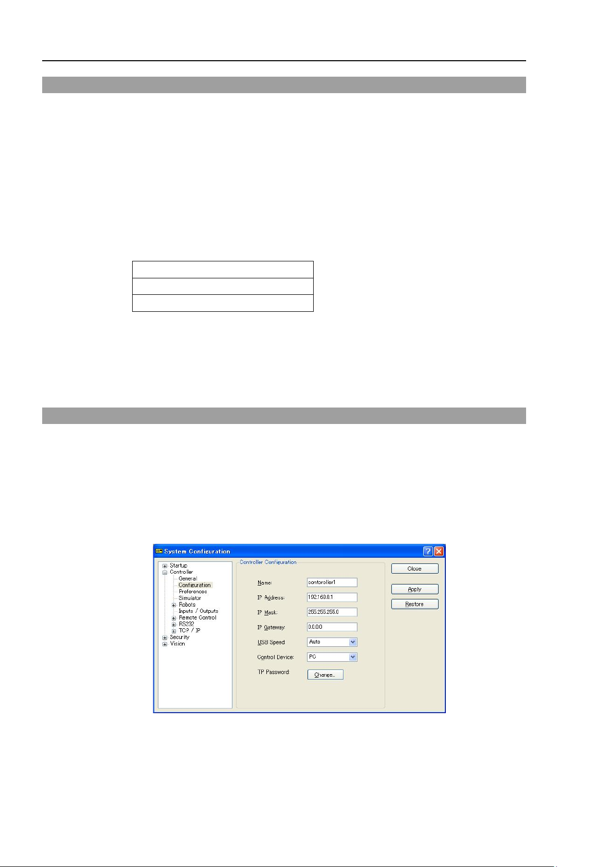
Setup & Operation 9. LAN (Ethernet Communication) Port
Private Address List
10.0.0.1
to
10.255.255.254
172.16.0.1
to
172.31.255.254
192.168.0.1
to
192.168.255.254
9.2 IP Address
Set the proper IP address or subnet mask depending on the Manipulator and development
PC configuration to use the LAN port.
Do not input a random value for the IP address of the network configured TCP/IP. This
is the only address that specifies the computer using an Internet connection.
The IP address is assigned from the company or organization that has control of IP
address.
Use an address from the following Internet private environment such as P2P or line.
Make sure that the address is not redundantly assigned inside the closed network.
The following is the configuration of the Controller Manipulator at delivery.
IP Address : 192.168.0.1
IP Mask : 255.255.255.0
IP Gateway : 0.0.0.0
9.3 Changing Manipulator IP Address
In this section, the procedure to change the Manipulator IP address when connecting
Manipulator development PC connection port and the development PC by the USB cable
is indicated.
(1) For connection between the development PC and the Manipulator.
Refer to Setup & Operation: 7. Development PC Connection Port.
(2) Select the EPSON RC+ 7.0 menu-[Setup]-[Controller] to display the following dialog
box.
80 V T R ev.6
Page 97
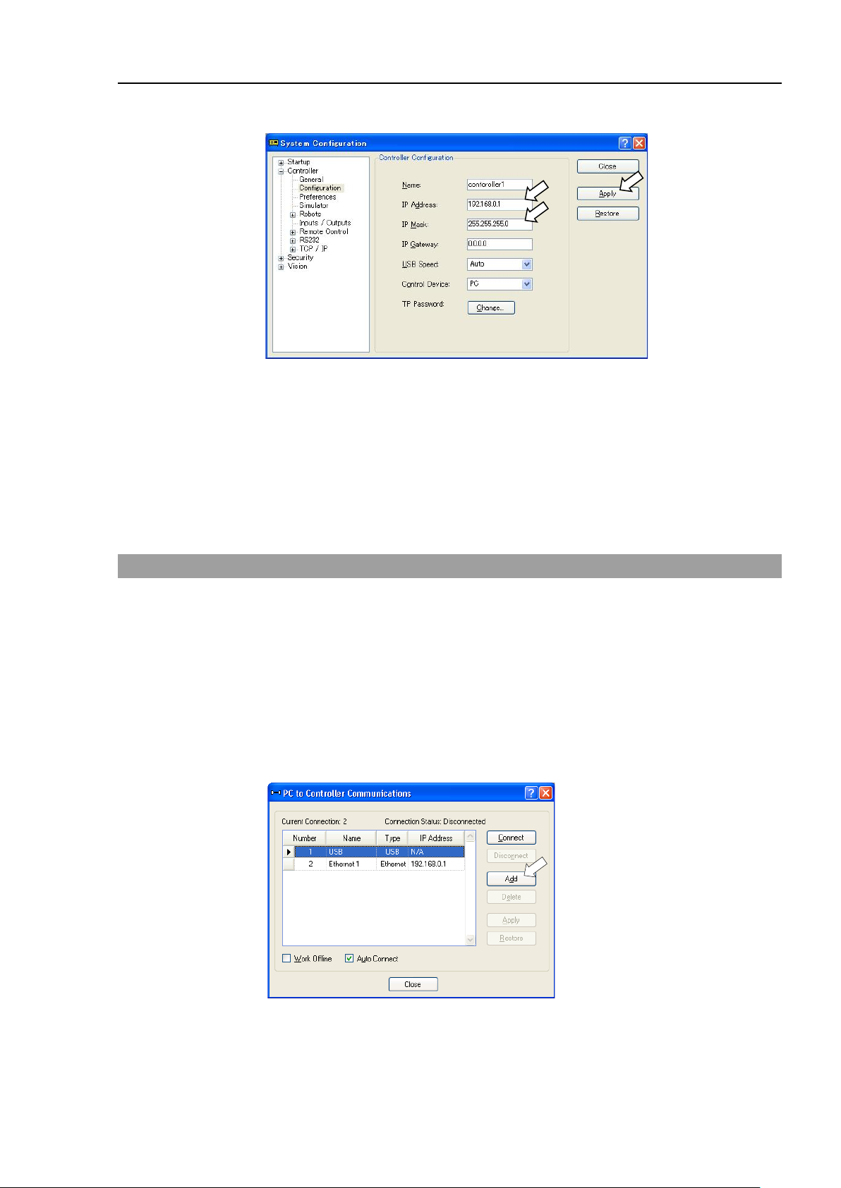
Setup & Operation 9. LAN (Ethernet Communication) Port
NOTE
(3) Select [Controller]-[Configuration].
(4) Enter the proper IP address and subnet mask and click the <Apply> button.
(5) Click the <Close> button. The Manipulator reboots automatically.
IP address configuration is completed and the Manipulator reboot dialog box
disappears.
When the Manipulator and the development PC are connected via the Ethernet, the
Manipulator IP address can also be changed. However, Manipulator and the
development PC do not connect automatically after rebooting the Manipulator at Ethernet
connection.
9.4 Connection of Development PC and Manipulator with Ethernet
Connection between the development PC and the Manipulator is shown below.
(1) Connect the development PC and the Manipulator using the Ethernet cable.
(2) Turn ON the Manipulator.
(3) Start EPSON RC+ 7.0.
(4) Display the [PC to Controller Communication] dialog box from [Setup] in EPSON
RC+ 7.0 menu.
(5) Click the <Add> button.
VT Rev. 6 81
Page 98
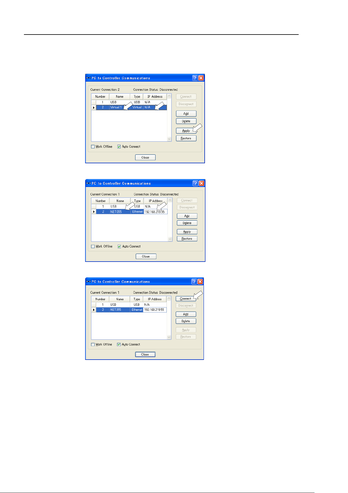
Setup & Operation 9. LAN (Ethernet Communication) Port
(6) Connection “No.2” is added. Set the following and click the <Apply> button.
Name : Valid value to identify the Manipulator to connect
IP Address : IP address for Manipulator to connect
(7) [Name] and [IP Address] specified in procedure (6) is displayed.
(8) Make sure that “No.2” is selected, and click the <Connect> button.
82 V T R ev.6
Page 99
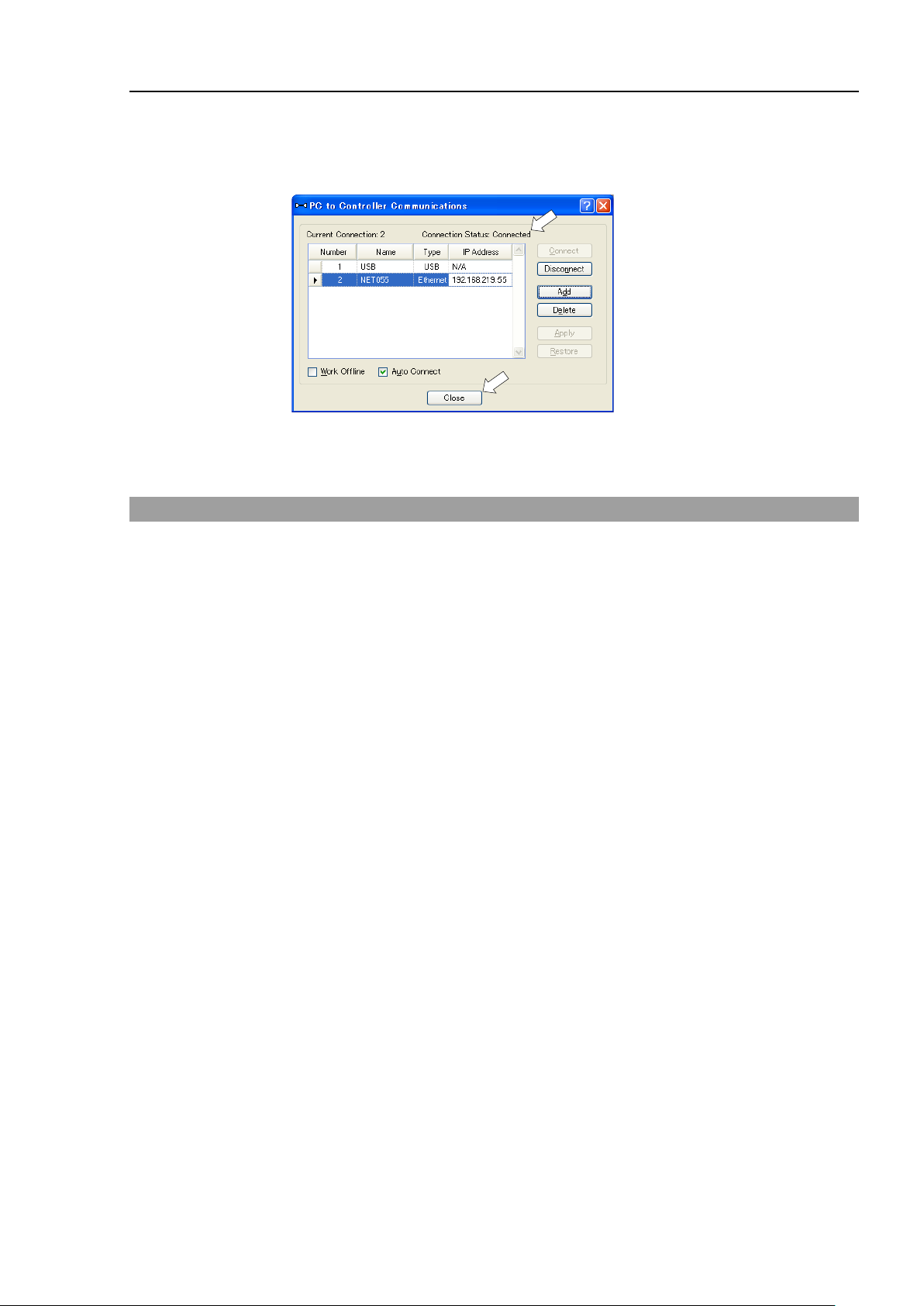
Setup & Operation 9. LAN (Ethernet Communication) Port
NOTE
(9) After the development PC and Manipulator connection is completed, “Connected” is
displayed in the [Connection status:]. Make sure that “Connected” is displayed and
click the <Close> button to close the [PC to Controller Communications] dialog box.
Connection between the development PC and the Manipulator is complete. Now the
robot system can be used via an Ethernet connection from EPSON RC+ 7.0.
9.5 Disconnection of Development PC and Manipulator with Ethernet
Disconnection of the development PC and the Manipulator is shown below.
(1) Display [PC-Controller Connection] dialog box from [Setup] in EPSON RC+ 7.0
menu.
(2) Click the <Disconnect> button.
Communication between the Manipulator and the development PC is disconnected
and the Ethernet cable can be removed.
If the Ethernet cable is removed when the Manipulator and the development PC is
connected, Emergency Stop occurs and the Manipulator stops. Be sure to click the
<Disconnect> button in the [PC to Controller Communications] dialog box before the
Ethernet cable is removed.
VT Rev. 6 83
Page 100

Setup & Operation 10. TP Port
10. TP Port
10.1 What is the TP Port?
Standard, Cleanroom model Protection model
The TP port connects the Teach Pendant (TP2, TP3) to the Manipulator.
Dedicated convert cable* is necessary if connecting TP2 to VT series Manipulator.
Contact the supplier of your region if only convert cable is necessary.
When nothing is connected to the TP port, Emergency Stop status occurs in the
Manipulator. When the Teach Pendant is not connected, connect the TP bypass plug.
Do not connect the devices except TP2, TP3 to the TP port. Connecting these devices
may result in malfunction of the device since the pin assignments are different.
10.2 Teach Pendant Connection
A dedicated cable is attached to the Teach Pendant. Connect this cable connector to the
TP port.
Communication is set automatically. Enable the Teach Pendant by one of the following
procedures.
- Insert the Teach Pendant connector to the Manipulator and turn ON the Manipulator.
- Insert the Teach Pendant connector while the Manipulator is turned ON.
Teach Pendant connection and disconnection from the Controller are allowed when the
Manipulator power is ON.
* TP Exchange Cable: R12NZ900L6
When the Teach Pendant connector is removed from the Manipulator with the mode
84 V T R ev.6
selector key switch of the Teach Pendant in the “Teach” position, the operation mode will
remain in the TEACH mode. The operation mode cannot be switched to AUTO mode.
Be sure to remove the Teach Pendant after switching the operation mode to “Auto” mode.
For details, refer to the following manuals:
Robot Contoroller RC700/RC90 Option Teach Pendant TP2.
Robot Contoroller RC700-A Option Teach Pendant TP3.
 Loading...