

Page 1
SERVICE MANUAL
Business Projector
EB-E01/X06/W06/E10
EB-X51/W51/E20/W52
Electric shock may result if you operate carelessly because there is electric charge remaining to reduce
power consumption in the Power Supply.
Make sure to follow the procedure below.
" 3.3.14 PS Ballast Assy (p122) "
INTERNAL USE ONLY
Page 2

EB-E01 series
INTERNAL USE ONLY
NOTICE
All rights reserved. No part of this manual may be reproduced, stored in retrieval system, or transmitted in any form or by any means, electronic, mechanical,
photocopying, recording, or otherwise, without prior written permission of SEIKO EPSON CORPORATION.
The contents of this manual should be handled with sufficient consideration for confidentiality reasons.
After publication of this manual, the parts and mechanism may be subject to change for improvement of their performance. Therefore, note that the descriptions
given in this manual may not coincide with the actual machine.
Other company or product names used herein are for identification purpose only and may be trademarks or registered trademarks of their respective owners.
EPSON disclaims any and all rights in those marks.
EPSON is a registered trademark of Seiko Epson Corporation.
Other product names used herein are for identification purpose only and may be trademarks or registered trademarks of their respective owners.
Copyright 2020 SEIKO EPSON CORPORATION.
SEIKO EPSON 2 Revision A
Page 3

EB-E01 series
INTERNAL USE ONLY
About This Manual
This manual describes basic functions, theory of electrical and mechanical operations, maintenance and repair procedures of the product.
The instructions and procedures included herein are intended for the experienced repair technicians, and attention should be given to the precautions on the preceding page.
CHAPTER 1. PRODUCT DESCRIPTIONS
Provides a general overview of the features and specifications of the product.
CHAPTER 2. TROUBLESHOOTING
Explains basic confirmation items for identifying the location of obstacle based on defects and abnormal symptoms.
CHAPTER 3. DISASSEMBLY / ASSEMBLY
Describes the step-by-step procedures for disassembling and assembling the main component units and parts of the product.
CHAPTER 4. APPENDIX
Provides preventive maintenance procedures for servicing the product.
SEIKO EPSON 3 Revision A
Page 4
EB-E01 series
INTERNAL USE ONLY
IMPORTANT PRECAUTIONS IN SAFETY AND MAINTENANCE PERFORMANCE
Here describes the important points to keep in mind in repair and maintenance performance.
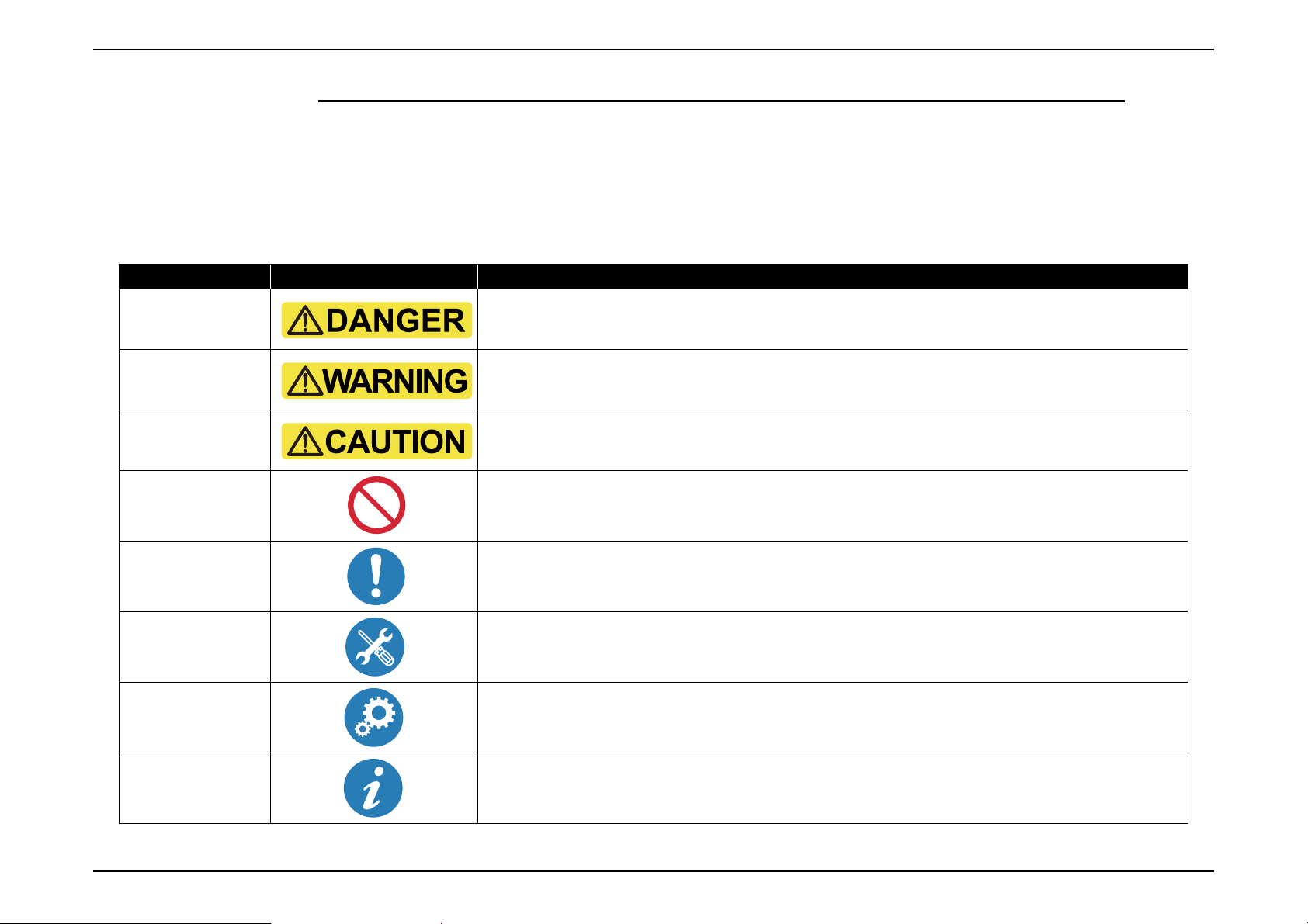
SYMBOLS
To prevent injury to the repair technicians and to protect the devices, the categorized safety instructions are provided in this manual with the symbols below. Be sure to read and
understand their meanings before proceeding to the next section.
Category Symbol Meaning
Danger
Warning
Caution
Prohibited
Matter
Instruction
Reassembly
Setting/
Maintenance
Indicates an extremely hazardous operation which, if ignored or operated incorrectly, could result in serious or
fatal personal injury.
Indicates a potentially hazardous operation which, if ignored or operated incorrectly, could result in serious or
fatal personal injury.
Indicates a potentially hazardous operation which, if ignored or operated incorrectly, could result in minor injury
or damage to equipment.
Indicates a prohibited action or operation in repair and maintenance performance.
Indicates a compulsory action or operation that must be carried out in repair and/or maintenance.
Indicates a compulsory action or operation for reassembly of disassembled parts that must be carried out in repair
and/or maintenance.
Indicates a compulsory action or operation for settings or maintenance that must be carried out in repair and/or
maintenance.
Point
Indicates reference information in repair and/or maintenance.
SEIKO EPSON 4 Revision A
Page 5
EB-E01 series
INTERNAL USE ONLY
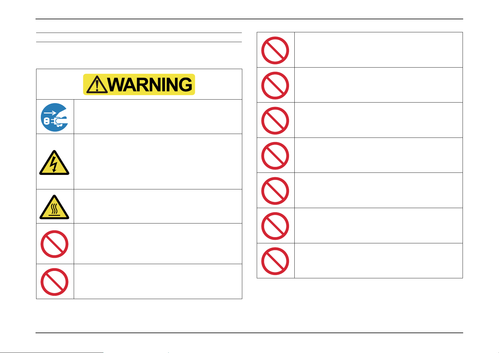
SAFETY INSTRUCTIONS
The precautionary measures itemized below should be fully understood when
performing repair and maintenance procedures.
When disassembling/assembling, be sure to turn off the power
switch and pull out the power cable from the projector beforehand.
Be extremely careful about the current-carrying part during a test
operation, signal measurement or any other situations that is
necessary to perform the repair/maintenance work with the power
turned on and the cover removed.
Take off the things made of metal (such as a wrist watch, cuff
buttons, rings, tie pin, etc.) which may come in contact with the
parts inside the projector.
Do not touch the lamp assy. or the parts around it. They are
extremely hot even after completing the cooling down operation,
and may cause a burn injury. Therefore, leave the unit until it
becomes cool enough before performing maintenance work.
Never let the safety devices mounted in this product inactivated,
modify the safety devices or replace them with the ones that are not
designated for any reason whatsoever. (Such actions may endanger
the projector's safety operation and may result in a fire or serious
injury.)
Never peer through the projection lens during repair/maintenance
work when the power is on. (Such an action may cause a visual
disability because of a very strong light emission.)
Never use a deformed plug or a damaged power cable to this
product. If any deformations or damages are found on the power
cable or plug section, replace it with a new specified power cable.
Never use the air blowers that contain flammable gas in repair/
maintenance work.
Never use or replace with any service parts that is not specified by
EPSON.
Do not disassemble any parts or components not specified in this
manual.
Do not apply any shock or vibration. (Otherwise, misalignment of
the optical parts inside the engine may cause irregular reflection of
the light and may result in burn (smoke) or damage to the internal
parts.)
Do not touch any parts such as inorganic polarizers that are
instructed not to.
Never modify the product for any reason whatsoever. (Except for a
case that is under the instructions to do so. In such a case,
understand the instructions thoroughly in advance and perform
modification appropriately.)
SEIKO EPSON 5 Revision A
Page 6
EB-E01 series
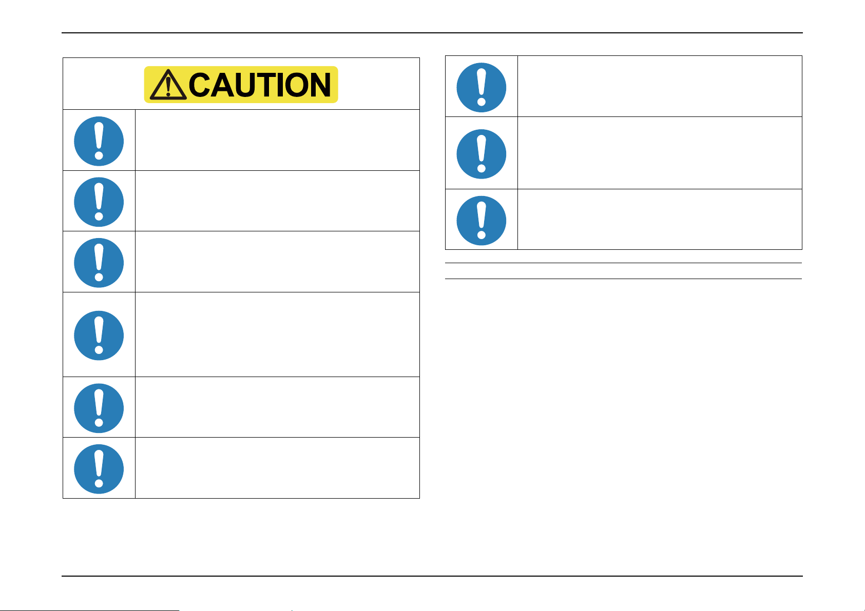
Be sure to perform the repair/maintenance work on the even and
stable work bench to prevent the product from dropping down or
mal-operation due to the improper setting of the product.
Be sure to take off the metal products such as wrist watch, cuff
buttons, rings, tie pin etc. in repair and/or maintenance to avoid
unsafe situations.
Be sure to wear the gloves during the repair/maintenance work to
avoid injuries by the parts with sharp edges such as metal plate or
the like.
INTERNAL USE ONLY
Be careful not to drop a metal part such as a screw, a washer, or a
clip into the inside of the product. If such cases should occur
accidentally, never turn on the power supply until all the dropped
parts are found and removed.
After reassembling the product, check the followings before
turning the power on.
All the parts and screws are installed and secured to the proper
positions.
No cables are caught in the metal frames.
If there are accumulated dust or foreign objects inside the product,
make sure to remove them before disassembling/reassembling the
product.
OTHER CAUTION
To protect sensitive circuitry, follow the instructions below.
When disassembling or reassembling, be sure to wear static
discharge equipment such as an anti-static wrist strap and a mat.
Since the lamp of this product contains mercury, be sure to dispose the used lamp
pursuant to the government’s law and regulations.
When replacing the circuit component such as a board or the
optical engine, be sure to contact the anti-static case containing
the new one to the metal part of this product before taking it out.
When performing the repair/maintenance work, be sure to use the
specified tools and follow the instructions that are specified in the
documents (service manual etc.) concerning to this product.
When carrying out the test operation, do not block the intake and
exhaust ducts.
(Such an action raises the internal temperature and may cause a
fire or a damages to the internal parts of this product.)
SEIKO EPSON 6 Revision A
Page 7
EB-E01 series
INTERNAL USE ONLY
REVISION HISTORY
After first release of this manual, the parts and mechanism may be subject to change for improvement of their performance and the manual may be revised. Be sure to always keep
this manual up to date.
Revision Date Page of change Detail of change
A 2020.1.21 all
First Release
SEIKO EPSON 7 Revision A
Page 8

EB-E01 series
INTERNAL USE ONLY
Contents
Chapter 1 Product Description
1.1 Product Description .............................................................................................. 11
1.2 Specifications ....................................................................................................... 12
1.3 Dimensions ........................................................................................................... 20
1.4 Ceiling Mount....................................................................................................... 24
Chapter 2 Troubleshooting
2.1 Required Tools ..................................................................................................... 33
2.2 Troubleshooting Procedure .................................................................................. 34
2.3 Exterior Check...................................................................................................... 36
2.4 Troubleshooting from the Device Names............................................................. 37
2.5 Error Indication and Problem diagnosis ............................................................... 39
2.5.1 Troubleshooting based on LED Indications ................................................ 39
2.5.2 Troubleshooting by Error Names ................................................................ 43
2.5.3 Troubleshooting without Error Indications ................................................. 47
2.5.4 Troubleshooting on image abnormality ....................................................... 51
2.5.5 Cable connection on the MA Board and error symptoms .......................... 53
2.6 Parts Layout Diagrams ......................................................................................... 58
Chapter 3 Disassembly and Assembly
3.1 Precautions ........................................................................................................... 64
3.1.1 General Cautions in operation ..................................................................... 64
3.1.2 Precautions................................................................................................... 65
3.1.3 Workflow..................................................................................................... 65
3.1.4 Tools ............................................................................................................ 66
3.1.4.1 Tool List.............................................................................................. 66
3.1.4.2 Recommended Tool List..................................................................... 66
3.1.5 How to unlock connectors for FFC/FPC ..................................................... 67
3.2 Flowchart.............................................................................................................. 70
3.2.1 Standard operation time............................................................................... 70
3.3 Disassembly and Assembly.................................................................................. 73
3.3.1 Air Filter ...................................................................................................... 73
3.3.2 Lamp............................................................................................................ 74
3.3.3 Front Foot .................................................................................................... 75
3.3.4 Rear Foot ..................................................................................................... 76
3.3.5 Rear Case..................................................................................................... 77
3.3.6 Upper Case (Assy)....................................................................................... 80
3.3.6.1 SW Board............................................................................................ 84
3.3.6.2 H Key Assy/Upper Case..................................................................... 86
3.3.6.3 Shutter................................................................................................. 87
3.3.6.4 Upper Case.......................................................................................... 89
3.3.7 WFD Board.................................................................................................. 94
3.3.8 P3dash Module ............................................................................................ 96
3.3.9 RTC Board................................................................................................... 97
3.3.10 MA Board Assy....................................................................................... 100
3.3.10.1 Speaker 16W................................................................................... 105
3.3.10.2 IF Board .......................................................................................... 106
3.3.11 Optical Engine (Assy) ............................................................................. 113
3.3.11.1 Auto Iris Assy ................................................................................. 115
3.3.11.2 Focus Ring/Zoom Ring................................................................... 116
3.3.12 EX Duct (Assy) ....................................................................................... 118
3.3.12.1 EX Fan/TH Board........................................................................... 119
3.3.13 Lamp Fan (Assy) ..................................................................................... 120
3.3.13.1 Lamp Fan/Speaker 5W ................................................................... 121
3.3.14 PS Ballast Assy........................................................................................ 122
3.3.15 P4combo Module..................................................................................... 128
3.3.16 INT Duct (Assy) ...................................................................................... 129
3.3.16.1 IR Board.......................................................................................... 131
3.3.16.2 INT Fan/TH Board.......................................................................... 132
3.3.17 Filter Boards ............................................................................................ 135
3.3.18 Lower Case/IR Board .............................................................................. 136
3.4 Shortest removal procedures of identified failed parts....................................... 137
3.4.1 Speaker ...................................................................................................... 137
3.4.2 IR Board .................................................................................................... 138
3.4.3 LMP Thermistor ........................................................................................ 139
3.4.4 EX Fan....................................................................................................... 140
3.5 Individual Function Check After Repair ............................................................ 141
3.5.1 Safety Check after Servicing ..................................................................... 142
SEIKO EPSON 8 Revision A
Page 9

EB-E01 series
INTERNAL USE ONLY
3.5.1.1 Insulation resistance test ................................................................... 143
3.5.1.2 Ground continuity check................................................................... 144
3.5.1.3 Illumination check ............................................................................ 144
3.5.2 Initialization............................................................................................... 145
3.5.3 Operation Check for control panel ............................................................ 145
3.5.4 Operation Check for remote controller...................................................... 145
3.5.5 Operation Check for video input/output .................................................... 146
3.5.6 Operation Check for audio input/output .................................................... 146
3.5.7 Communication Check .............................................................................. 147
3.5.8 Internal Cable Connection Check.............................................................. 147
3.5.9 The service tools and the adjustment tasks list which required before
and after parts replacement.................................................................................. 148
3.5.10 Service tool list ........................................................................................ 150
3.6 Writing the DR Data........................................................................................... 152
3.6.1 Overview.................................................................................................... 152
3.6.2 Preparation................................................................................................. 153
3.6.3 Operating Procedure .................................................................................. 153
3.6.3.1 Workflow .......................................................................................... 153
3.6.3.2 Check in advance .............................................................................. 154
3.6.3.3 Replacing the Optical Engine ........................................................... 156
3.6.3.4 Replacing the MA Board .................................................................. 158
3.7 G Sensor Calibration .......................................................................................... 161
3.7.1 Overview.................................................................................................... 161
3.7.2 Preparation................................................................................................. 161
3.7.3 Procedure ................................................................................................... 161
3.8 LCD Alignment .................................................................................................. 162
3.8.1 Overview.................................................................................................... 162
3.8.2 Pixel color shift confirmation method ....................................................... 162
3.8.3 LCD alignment activation method............................................................. 162
3.8.3.1 Adjustment method........................................................................... 164
3.9 Part Names List .................................................................................................. 166
4.1.2.2 Confirmation method which connects PC with projector................. 184
4.1.2.3 Confirmation method using a USB memory .................................... 188
4.1.3 Initializing (Resetting)............................................................................... 190
Chapter 4 Appendix
4.1 AS (After Service) Menu.................................................................................... 171
4.1.1 How To Display the AS (After Service) Menu ......................................... 171
4.1.1.1 How to enter the AS menu................................................................ 171
4.1.1.2 Menu Contents .................................................................................. 171
4.1.2 Confirmation method using IPS tool ......................................................... 184
4.1.2.1 Preparation ........................................................................................ 184
SEIKO EPSON 9 Revision A
Page 10

PRODUCT DESCRIPTION
CHAPTER
1
INTERNAL USE ONLY
Page 11
EB-E01 series Product Description INTERNAL USE ONLY
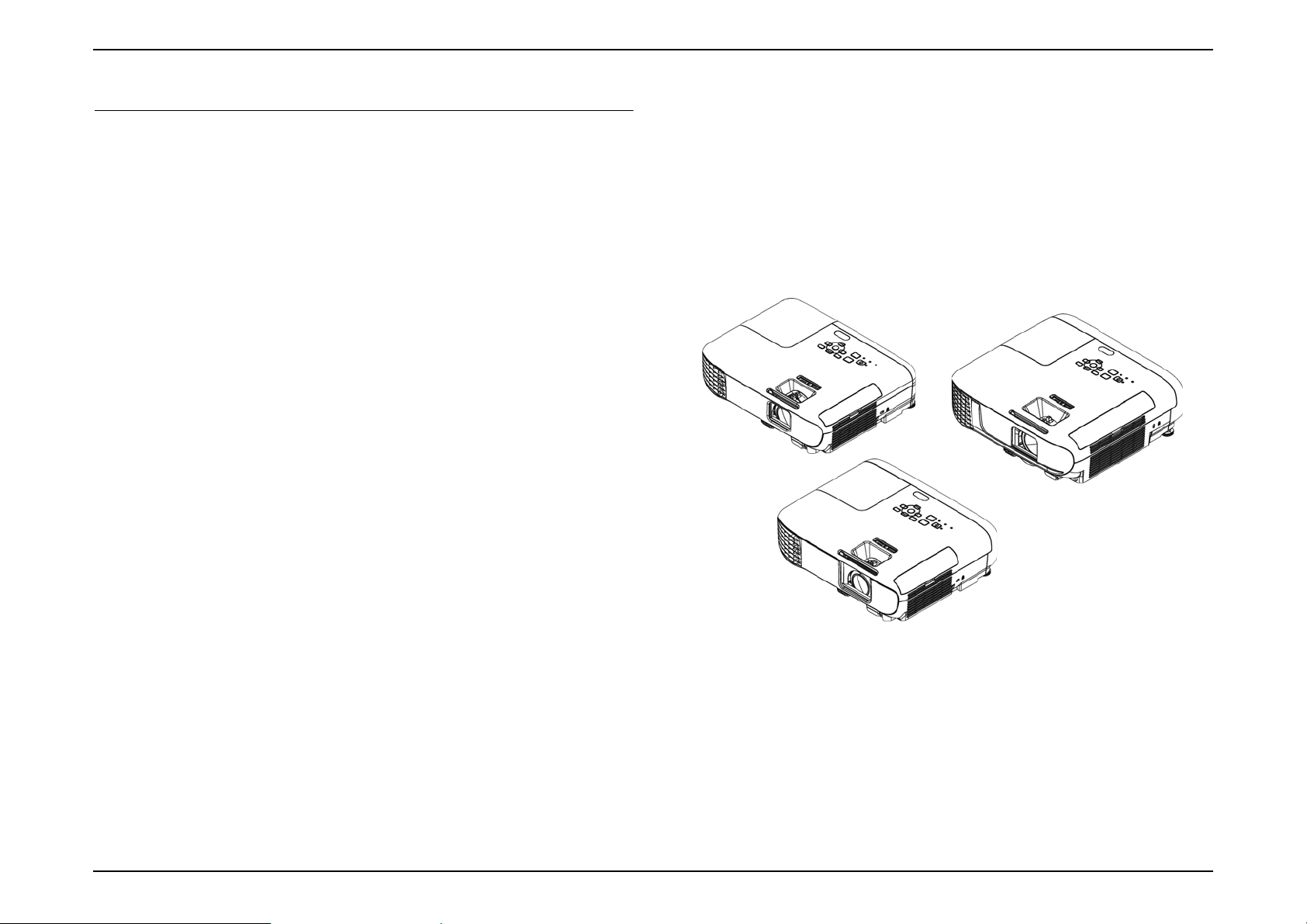
1.1 Product Description
This projector comes with this special features. Refer to these sections for more
details.
Quick and Easy Setup
Direct Power On feature to turn on the projector as soon as you plug it
in.
Auto Power On feature to turn on the projector when the projector
detects an image signal from the port you specified as the Auto Power
On source.
Home screen feature to easily select an input source and useful
functions.
Automatic vertical keystone correction always displays a rectangular
screen (Auto V-Keystone).
Horizontal correction slider to quickly correct the lateral strain of the
projected image. Sliding horizontal correction is convenient when the
projector cannot be parallel to the screen.
(Except EB-E01/E10)
Easy Wireless Projection (EB-FH52/992F EH-TW750 only)
Screen Mirroring allows a wireless connection between the projector
and a mobile device compatible with Miracast.
Epson iProjection (Windows/Mac) to project up to four images at the
same time by splitting the projected screen. You can project images
from computers on the network, or from smartphones or tablet devices.
Flexible Connectivity
Enhanced security functions
Operation button lock function
Security cable installation
Remote password
Sliding Lens Cover for Easy Projection And Storage
(other than EB-E01/E10)
No cool-down period is needed.
Auto Iris
External View
This projector can be connected to computers, video equipment,
smartphones, tablet terminals, and other devices.
Slide Show Function (except EB-E01/E10)
The images in a USB storage can be projected without using a
computer
Equipped with USB terminal (Type A)
SEIKO EPSON 11 Revision A
Page 12
EB-E01 series Product Description INTERNAL USE ONLY
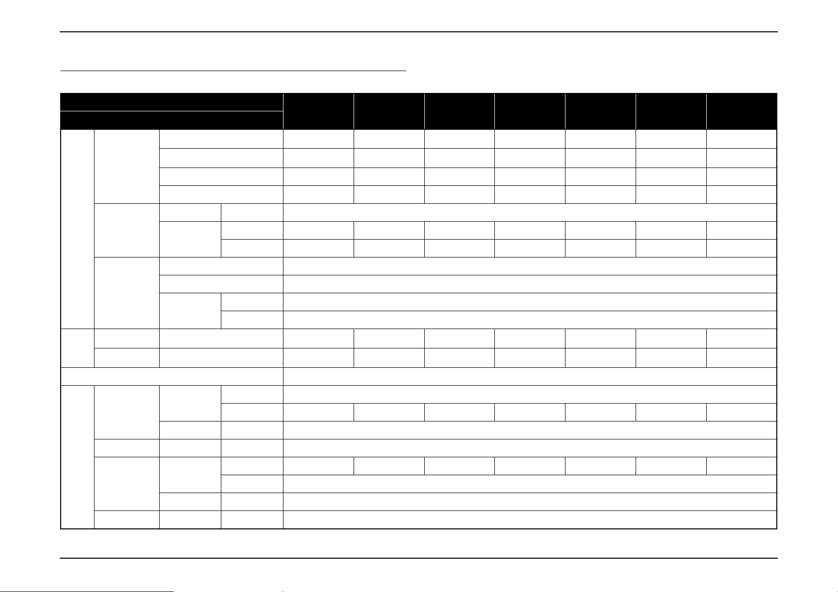
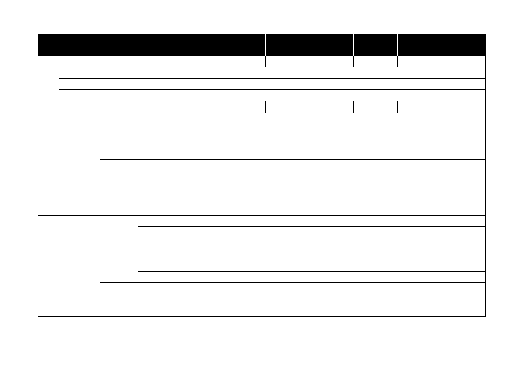
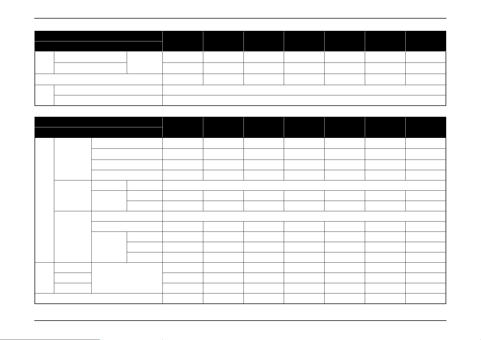
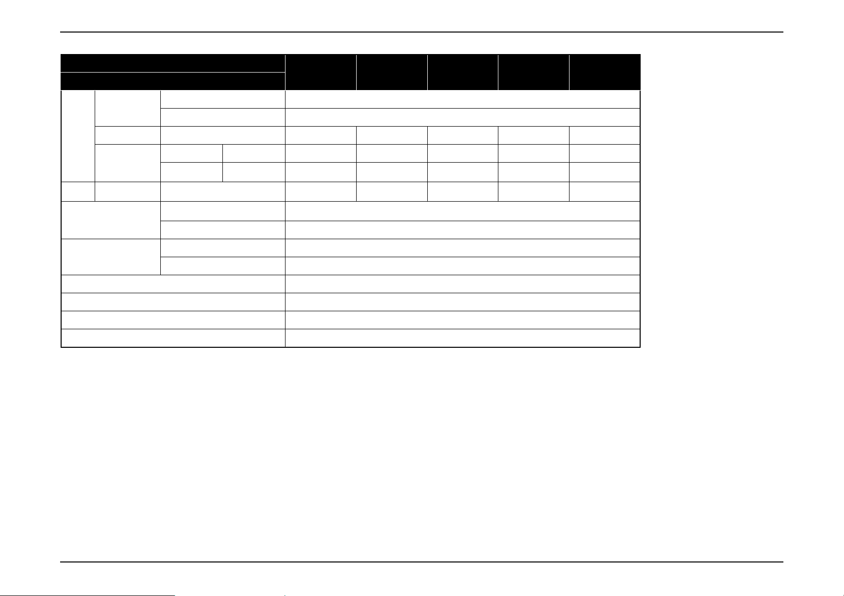
1.2 Specifications
EB-E01/X06/W06/E10/X51/W51/W52
Model
Item
Size
Pixel number
LCD
Native resolution XGA XGA WXGA XGA XGA WXGA WXGA
Aspect ratio 4:3 4:3 16:10 4:3 4:3 16:10 16:10
EB-E01 EB-X06 EB-W06 EB-E10 EB-X51 EB-W51 EB-W52
0.55 inch
(C2fine)
786,432 pixels
(1024 x 768) x 3
0.55 inch
(C2fine)
786,432 pixels
(1024 x 768) x 3
0.59 inch
(C2fine)
1,024,000 pixels
(1280 x 800) x 3
0.55 inch
(C2fine)
786,432 pixels
(1024 x 768) x 3
0.55 inch
(C2fine)
786,432 pixels
(1024 x 768) x 3
0.59 inch
(C2fine)
1,024,000 pixels
(1280 x 800) x 3
1,024,000 pixels
(1280 x 800) x 3
0.59 inch
(C2fine)
Specific
ation
of main
part
Brightn
ess
Sound output Monaural: 2W x 1
I/O
Projection Lens
Lamp
Normal mode
Eco mode
Video input
Video output Analog D-sub 15pin —
Audio
Focus Type Manual
Zoom
Type UHE
Power consumption 210W
Life
Color mode: Dynamic,
Zoom: Wide
Color mode: Dynamic,
Zoom: Wide
Analog
Digital HDMI 1
Input
Type Digital Manual Manual Digital Manual Manual Manual
Ratio 1-1.35 1-1.2 1-1.2 1-1.35 1-1.2 1-1.2 1-1.2
Normal 6,000 hours
Eco 12,000 hours
3,300lm 3,600lm 3,700lm 3,600lm 3,800lm 4,000lm 4,000lm
2,200lm 2,400lm 2,400lm 2,200lm 2,500lm 2,600lm 2,600lm
D-sub 15pin 1 (Blue molding)
RCA — 1 (Yellow) 1 (Yellow) — 1 (Yellow) 1 (Yellow) 1 (Yellow)
RCA (L/R)—11—111
Stereo mini —
Output Stereo mini —
Mic Input Stereo mini —
SEIKO EPSON 12 Revision A
Page 13
EB-E01 series Product Description INTERNAL USE ONLY
Model
Item
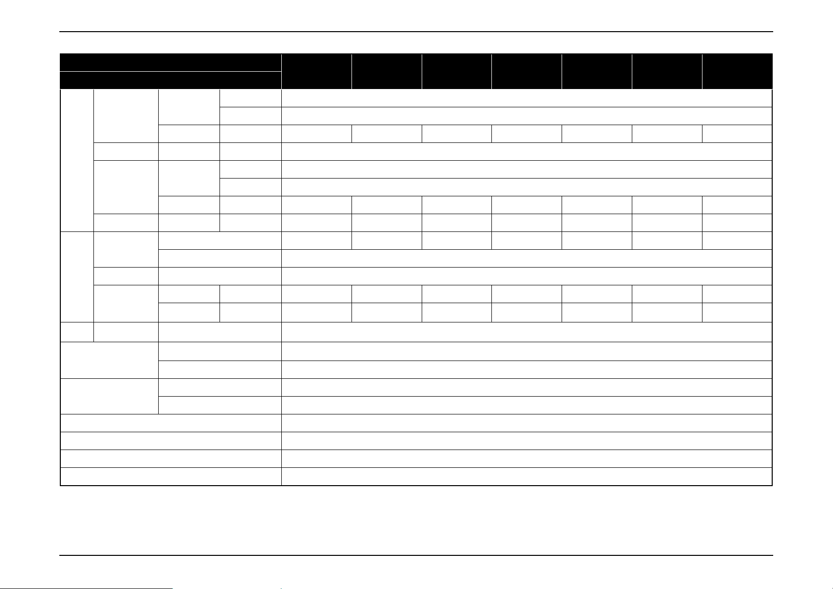
USB
I/O
I/O
Operating Temperature
Operating Altitude
Start-up period Less than 6 seconds
Warm-up period 30 seconds
Cool-down period Instant off
Power on was possible/impossible 100 - 240 V AC +/- 10%, 50/60 Hz
RS232C D-sub 9pin —
Network
Wireless
connection
Type A —11—111
Type B 1
Cable LAN RJ45 —
Wireless LAN
Screen Mirroring —
Temperature
Humidity 20% - 80% humidity
Normal 0 m to 3,048 m <0 ft to 10000 ft>
High altitude mode 1500 m <4921 ft> or more
USB Type A
(ELPAP11)
EB-E01 EB-X06 EB-W06 EB-E10 EB-X51 EB-W51 EB-W52
— Optional Optional — Optional Optional —
5°C to 40°C [41°F to 104°F] (Elevation 0 to 2,286 m)
5°C to 35°C [41°F to 95°F] (Elevation 2,287 m or more)
ON (Normal) 345W
ON (Eco) 235W
ON (Normal) 327W
ON (Eco) 235W 225W
Power
consum
ption
100-120V Area
(JAPAN, USA,
etc.)
220-240V Area
(Europe, etc.)
Rated Voltage & Current (Except Japan) 100 - 240 V AC 50/60 Hz 3.5A - 1.6A
Lamp
Standby (Network On) 2.0W
Energy Saving 0.3W
Lamp
Standby (Network On) 2.0W
Energy Saving 0.3W
SEIKO EPSON 13 Revision A
Page 14
EB-E01 series Product Description INTERNAL USE ONLY
Model
Item
Size
Weight
Fan
noise
Excluding feet
Unit: mm
Maximum Dimension
Normal mode 37 dB
Eco mode 28 dB
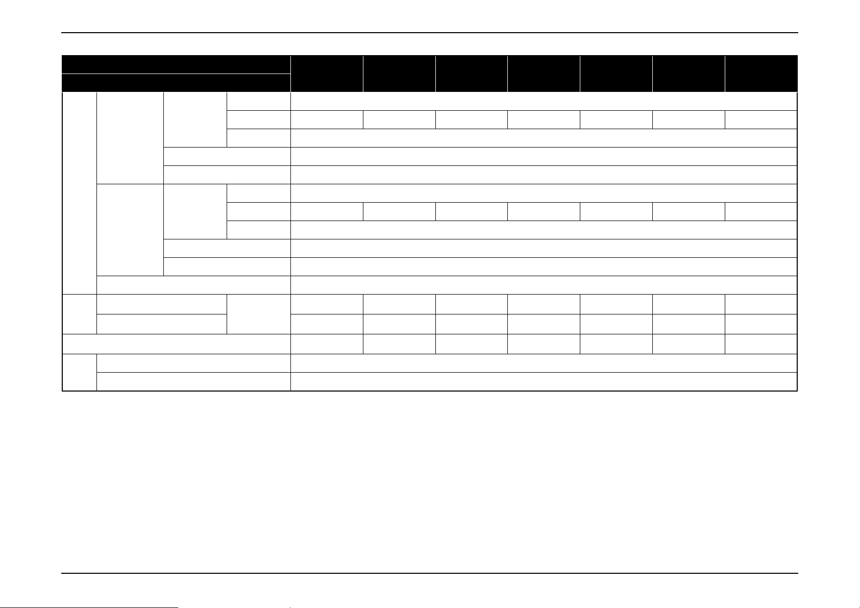
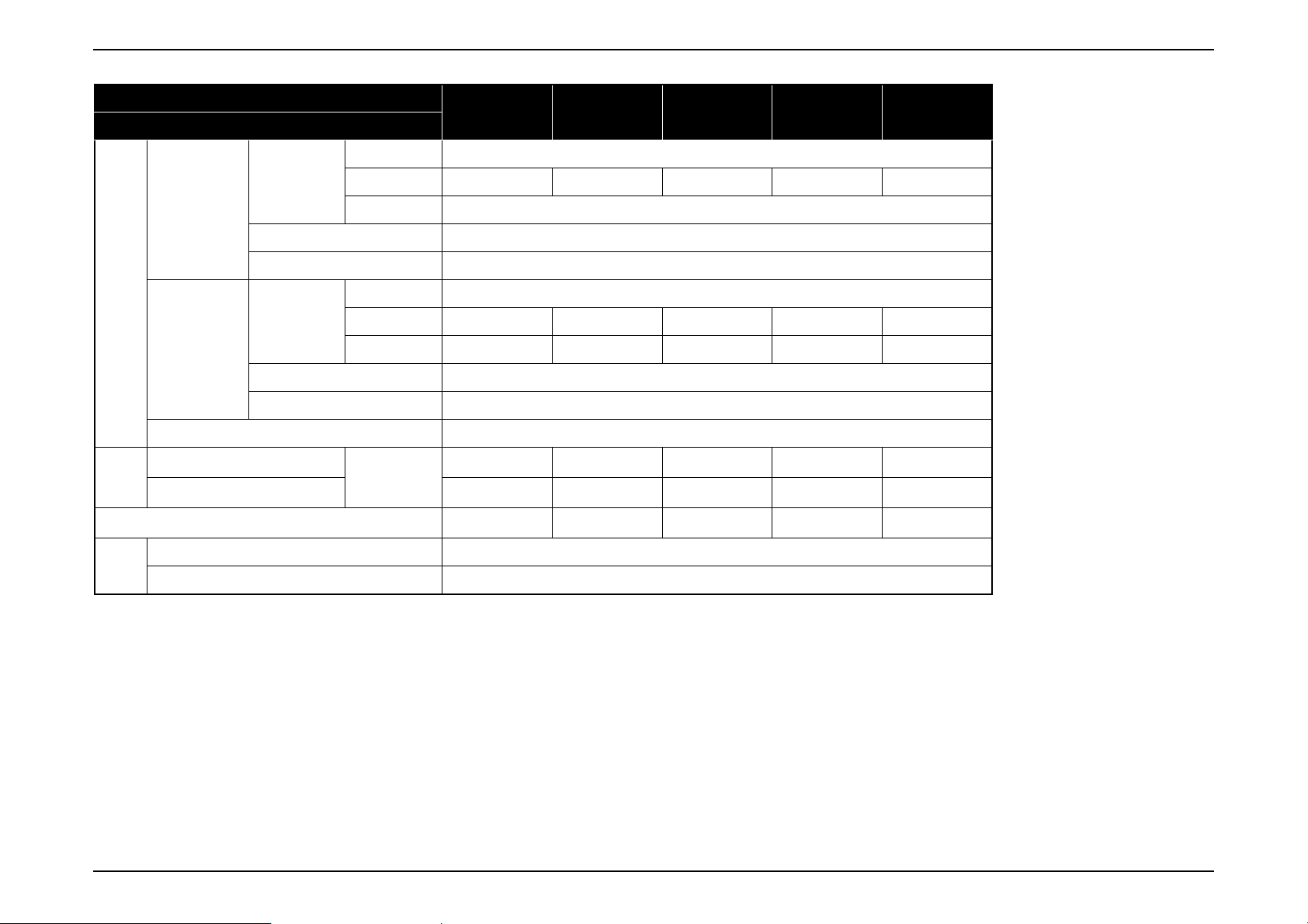
EB-E20/X49/W49/972/982W/118, PL 119W
Model
Item
Size
Pixel number
Native resolution XGA XGA WXGA XGA WXGA XGA WXGA
Aspect ratio 4:3 4:3 16:10 4:3 16:10 4:3 16:10
Focus Type Manual
Type Digital Manual Manual Manual Manual Manual Manual
Zoom
Ratio 1-1.35 1-1.2 1-1.2 1-1.6 1-1.6 1-1.2 1-1.2
Type UHE
Specific
ation
of main
part
LCD
Projection Lens
EB-E01 EB-X06 EB-W06 EB-E10 EB-X51 EB-W51 EB-W52
302(W) x 77 (H) x
234 (D)
302(W) x 82 (H) x
237 (D)
Approx. 5.29 lbs./
2.4 kg
EB-E20 EB-X49 EB-W49 EB-972 EB-982W EB-118 PL 119W
0.55 inch
(C2fine)
786,432 pixels
(1024 x 768) x 3
302(W) x 77 (H) x
234 (D)
302(W) x 82 (H) x
237 (D)
Approx. 5.51 lbs./
2.5 kg
0.55 inch
(C2fine)
786,432 pixels
(1024 x 768) x 3
302(W) x 77 (H) x
234 (D)
302(W) x 82 (H) x
237 (D)
Approx. 5.51 lbs./
2.5 kg
0.55 inch
(C2fine)
1,024,000 pixels
(1280 x 800) x 3
302(W) x 77 (H) x
234 (D)
302(W) x 82 (H) x
237 (D)
Approx. 5.29 lbs./
2.4 kg
0.55 inch
(C2fine)
786,432 pixels
(1024 x 768) x 3
302(W) x 77 (H) x
234 (D)
302(W) x 82 (H) x
237 (D)
Approx. 5.51 lbs./
2.5 kg
0.59 inch
(C2fine)
1,024,000 pixels
(1280 x 800) x 3
302(W) x 77 (H) x
234 (D)
302(W) x 82 (H) x
237 (D)
Approx. 5.51 lbs./
2.5 kg
0.55 inch
(C2fine)
786,432 pixels
(1024 x 768) x 3
302 (W) x 87 (H) x
302 (W) x 92 (H) x
Approx. 5.73lbs./
1,024,000 pixels
(1280 x 800) x 3
234 (D)
237 (D)
2.6 kg
0.59 inch
(C2fine)
Power consumption 210W 210W 210W 230W 230W 210W 210W
Lamp
Life
Normal mode
Brightn
ess
Sound output Monaural: 5W x 1 Monaural: 5W x 1 Monaural: 5W x 1
Medium mode — — 3,700lm 3,500lm 3,600lm 3,600lm 3,700lm
Eco mode 2,200lm 2,400lm 2,600lm 2,500lm 2,600lm 2,500lm 2,600lm
Color mode: Dynamic,
Zoom: Wide
Normal 6,000 hours 6,000 hours 8,000 hours 6,500 hours 6,500 hours 8,000 hours 8,000 hours
Medium — — 10,000 hours 10,000 hours 10,000 hours 10,000 hours 10,000 hours
Eco 12,000 hours 12,000 hours 17,000 hours 17,000 hours 17,000 hours 17,000 hours 17,000 hours
3,400lm 3,600lm 3,800lm 4,100lm 4,200lm 3,800lm 4,000lm
Monaural: 16W x 1 Monaural: 16W x 1 Monaural: 16W x 1 Monaural: 16W x 1
SEIKO EPSON 14 Revision A
Page 15
EB-E01 series Product Description INTERNAL USE ONLY
Video input
I/O
I/O
I/O
Operating Temperature
Video output Analog D-sub 15pin 1
Audio
Mic Input Stereo mini — — — 1 1 1 1
USB
RS232C D-sub 9pin 1 (for servicing only)
Network
Wireless
connection
Model
Item
Analog
DigitalHDMI1122222
Input
OutputStereo mini1111112
Type A —111111
Type B 1
Cable LANRJ45 —111111
Wireless LAN
Screen Mirroring —
Temperature
Humidity 20% - 80% humidity
D-sub 15pin 2 (Blue molding)
RCA 1 (Yellow)
RCA (L/R) 1
Stereo mini 2
USB TypeA
(ELPAP11)
EB-E20 EB-X49 EB-W49 EB-972 EB-982W EB-118 PL 119W
— 1 1 Optional Optional Optional 1
5°C to 40°C [41°F to 104°F] (Elevation 0 to 2,286 m)
5°C to 35°C [41°F to 95°F] (Elevation 2,287 m or more)
Operating Altitude
Start-up period Less than 6 seconds
Warm-up period 30 seconds
Cool-down period Instant off
Power on was possible/impossible 100 - 240 V AC +/- 10%, 50/60 Hz
Normal 0 m to 3,048 m <0 ft to 10000 ft>
High altitude mode 1500 m <4921 ft> or more
SEIKO EPSON 15 Revision A
Page 16
EB-E01 series Product Description INTERNAL USE ONLY
Power
consum
ption
Size
Weight
Fan
noise
Model
Item
ON (Normal) 345W
100-120V Area
Lamp
(JAPAN, USA,
etc.)
Standby (Network On) 2.0W
Energy Saving 0.3W
Lamp
220-240V Area
(Europe, etc.)
Standby (Network On) 2.0W
Energy Saving 0.3W
Rated Voltage & Current (Except Japan) 100 - 240 V AC 50/60 Hz 3.5A - 1.6A
Excluding feet
Maximum Dimension
Normal mode 37 dB
Eco mode 28 dB
ON (Medium) — — 303W 303W 303W 303W 303W
ON (Eco) 235W
ON (Normal) 327W
ON (Medium) — — 290W 290W 290W 290W 290W
ON (Eco) 225
Unit: mm
EB-E20 EB-X49 EB-W49 EB-972 EB-982W EB-118 PL 119W
302(W) x 87 (H) x
249 (D)
302(W) x 92 (H) x
249 (D)
Approx. 5.95 lbs./
2.7 kg
302(W) x 87 (H) x
249 (D)
302(W) x 92 (H) x
249 (D)
Approx. 5.95 lbs./
2.7 kg
302(W) x 87 (H) x
249 (D)
302(W) x 92 (H) x
249 (D)
Approx. 5.95 lbs./
2.7 kg
309 (W) x 90 (H) x
282 (D)
309 (W) x 105 (H)
x 293 (D)
Approx. 6.83 lbs./
3.1 kg
309 (W) x 90 (H) x
309 (W) x 105 (H)
x 293 (D)
Approx. 6.83 lbs./
282 (D)
3.1 kg
302 (W) x 87 (H) x
249 (D)
302 (W) x 92 (H) x
260 (D)
Approx. 6.17 lbs./
2.8 kg
302(W) x 87 (H) x
249 (D)
302(W) x 92 (H) x
260 (D)
Approx. 6.17 lbs./
2.8 kg
SEIKO EPSON 16 Revision A
Page 17
EB-E01 series Product Description INTERNAL USE ONLY
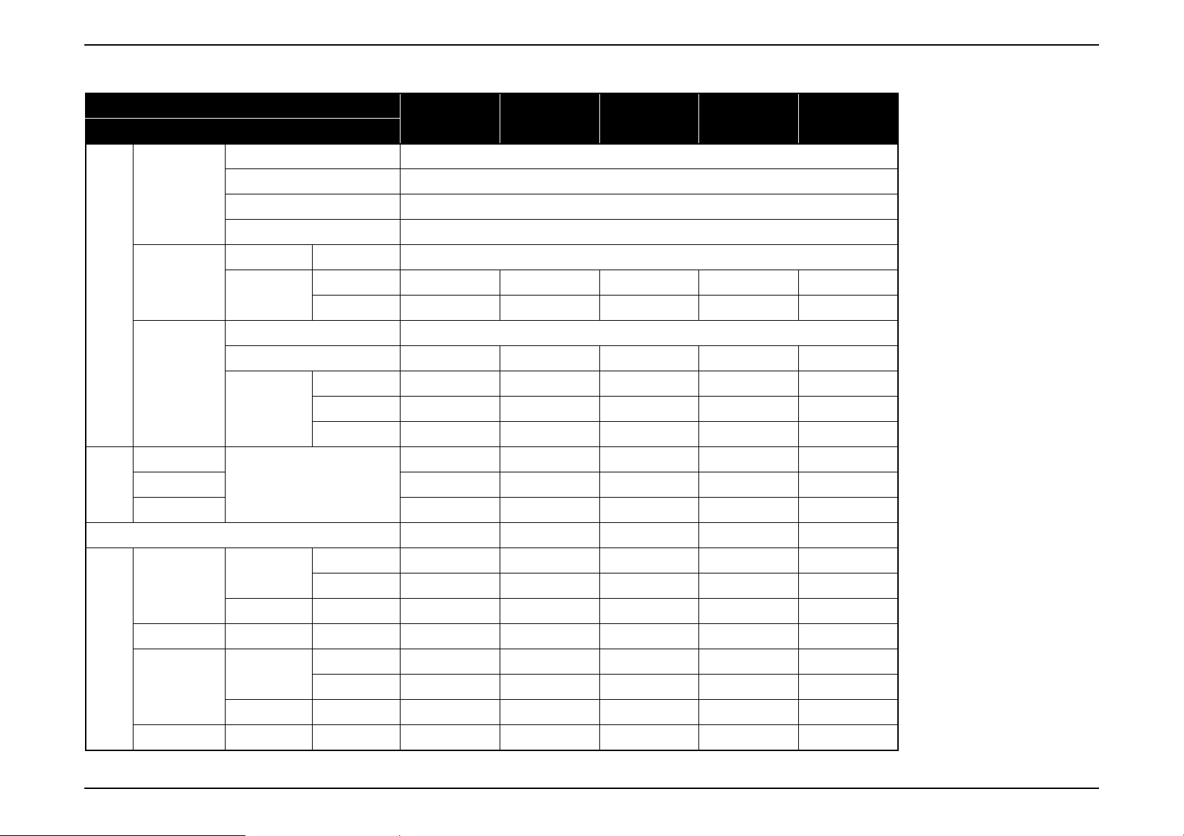
EB-FH06/FH52/992F, EH-TW740/TW750
Model
Item
Size 0.61 inch (C2fine)
EB-FH06 EB-FH52 EB-992F EH-TW740 EH-TW750
LCD
Specific
ation
of main
part
Brightn
ess
Sound output Monaural: 2W x 1
Projection Lens
Lamp
Normal mode
Medium mode — — 3,400lm — —
Eco mode 2,300lm 2,400lm 2,400lm 2,200lm 2,200lm
Video input
Pixel number 2,073,600 pixels (1920 x 1080) x 3
Native resolution Full HD
Aspect ratio 16:9
Focus Type Manual
Zoom
Type UHE
Power consumption 210W 230W 230W 210W 210W
Life
Color mode: Dynamic,
Zoom: Wide
Analog
Type Manual Manual Manual Digital Manual
Ratio 1-1.2 1-1.6 1-1.6 1-1.35 1-1.2
Normal 6,000 hours 5,500 hours 6,500 hours 6,000 hours 6,000 hours
Medium — — 10,000 hours — —
Eco 12,000 hours 12,000 hours 17,000 hours 12,000 hours 12,000 hours
3,500lm 4,000lm 4,000lm 3,300lm 3,400lm
D-sub 15pin 1 (Blue molding) 1 (Blue molding) 2 (Blue molding) — 1 (Blue molding)
RCA 1 (Yellow) 1 (Yellow) 1 (Yellow) — 1 (Yellow)
Monaural: 16W x 1 Monaural: 16W x 1
Monaural: 2W x 1 Monaural: 2W x 1
DigitalHDMI2 2212
I/O
Video output Analog D-sub 15pin — — 1 — —
Audio
Input
Output Stereo mini — — 1 1 1
Mic Input Stereo mini — — 1 — —
RCA (L/R)111—1
Stereo mini — — 2 — —
SEIKO EPSON 17 Revision A
Page 18
EB-E01 series Product Description INTERNAL USE ONLY
Model
Item
USB
I/O
I/O
Operating Temperature
Operating Altitude
Start-up period Less than 6 seconds
Warm-up period 30 seconds
Cool-down period Instant off
Power on was possible/impossible 100 - 240 V AC +/- 10%, 50/60 Hz
RS232C D-sub 9pin — —
Network
Wireless
connection
Type A 1
Type B 1
Cable LAN RJ45 — — 1 — —
Wireless LAN
Screen Mirroring — 1 1 — 1
Temperature
Humidity 20% - 80% humidity
Normal 0 m to 3,048 m <0 ft to 10000 ft>
High altitude mode 1500 m <4921 ft> or more
USB TypeA
(ELPAP10)
EB-FH06 EB-FH52 EB-992F EH-TW740 EH-TW750
1 (for servicing only)
Optional — 1 Optional —
5°C to 40°C [41°F to 104°F] (Elevation 0 to 2,286 m)
5°C to 35°C [41°F to 95°F] (Elevation 2,287 m or more)
——
SEIKO EPSON 18 Revision A
Page 19
EB-E01 series Product Description INTERNAL USE ONLY
Power
consum
ption
Size
Weight
Fan
noise
Model
Item
ON (Normal) 345W
100-120V Area
Lamp
(JAPAN, USA,
etc.)
Standby (Network On) 2.0W
Energy Saving 0.3W
Lamp
220-240V Area
(Europe, etc.)
Standby (Network On) 2.0W
Energy Saving 0.3W
Rated Voltage & Current (Except Japan) 100 - 240 V AC 50/60 Hz 3.5A - 1.6A
Excluding feet
Maximum Dimension
Normal mode 37 dB
Eco mode 28 dB
ON (Medium) — — 303W — —
ON (Eco) 235W
ON (Normal) 327
ON (Medium) — — 290W — —
ON (Eco) 235W 225W 225W 225W 225W
Unit: mm
EB-FH06 EB-FH52 EB-992F EH-TW740 EH-TW750
302(W) x 87 (H) x
249 (D)
302(W) x 92 (H) x
252 (D)
Approx. 5.95 lbs./
2.7 kg
309(W) x 90 (H) x
282 (D)
309(W) x 105 (H)
x 293 (D)
Approx. 6.83 lbs./
3.1 kg
309 (W) x 90 (H) x
282 (D)
309 (W) x 105 (H)
x 293 (D)
Approx. 6.83 lbs./
3.1 kg
302(W) x 87 (H) x
302(W) x 92 (H) x
Approx. 5.95 lbs./
249 (D)
252 (D)
2.7 kg
302(W) x 87 (H) x
249 (D)
302(W) x 92 (H) x
252 (D)
Approx. 6.17 lbs./
2.8 kg
SEIKO EPSON 19 Revision A
Page 20
EB-E01 series Product Description INTERNAL USE ONLY
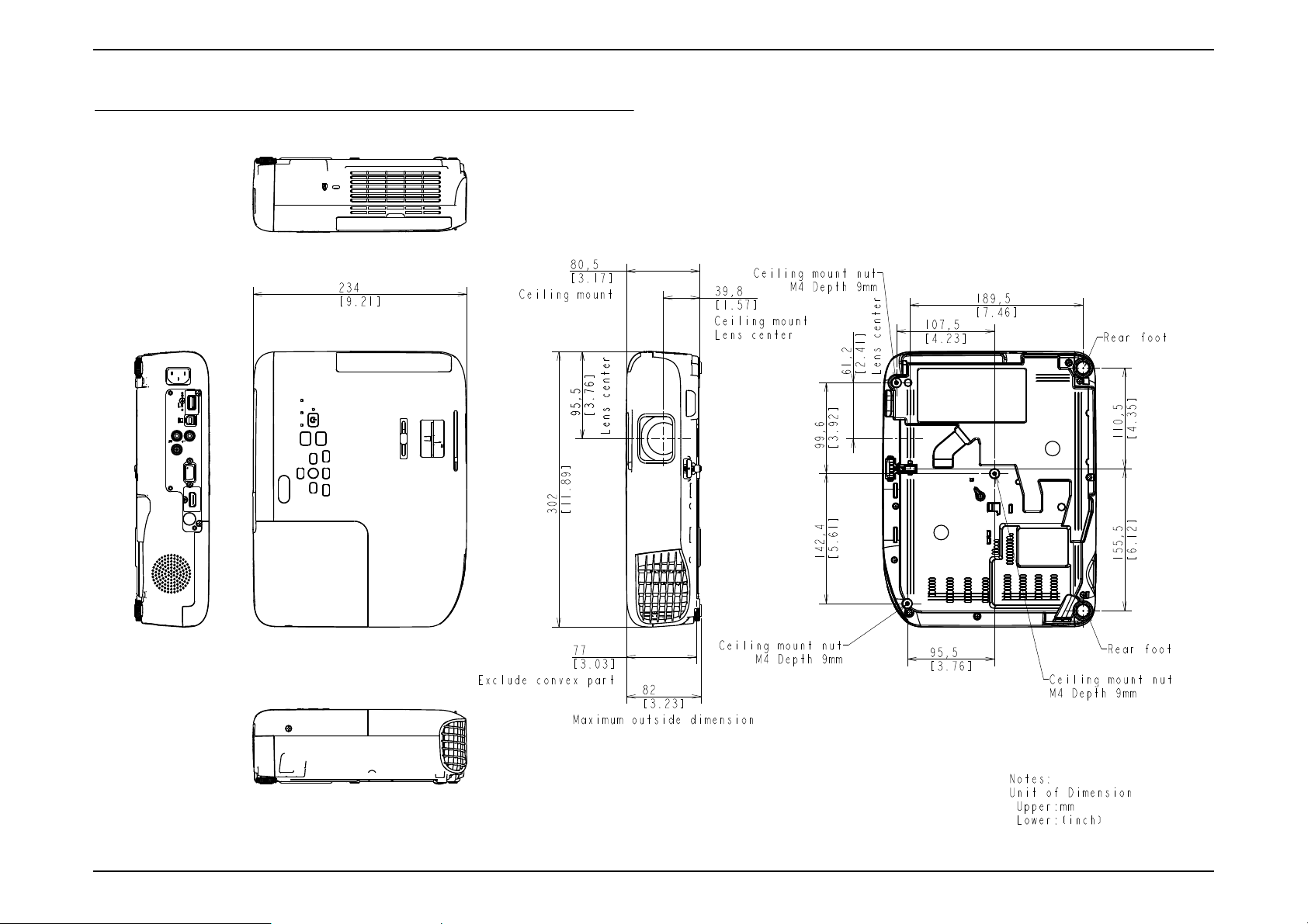
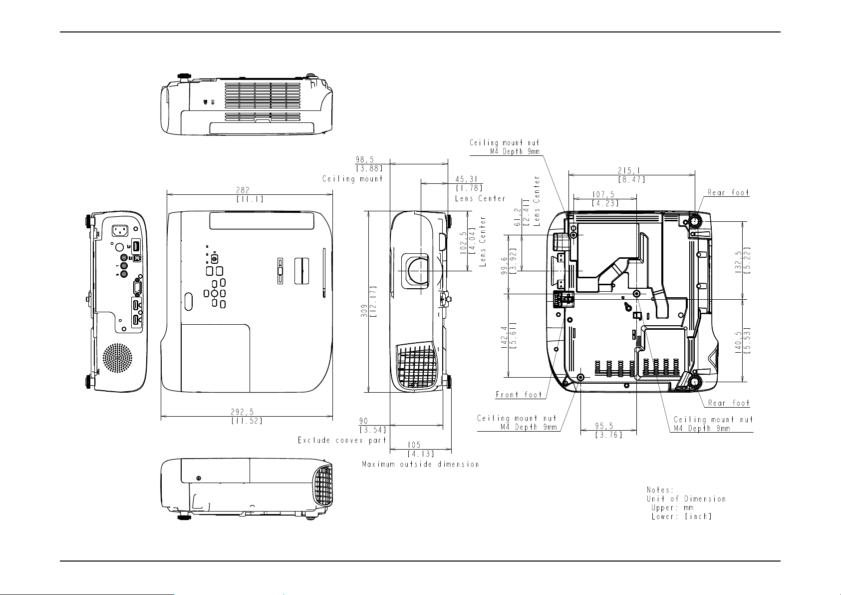
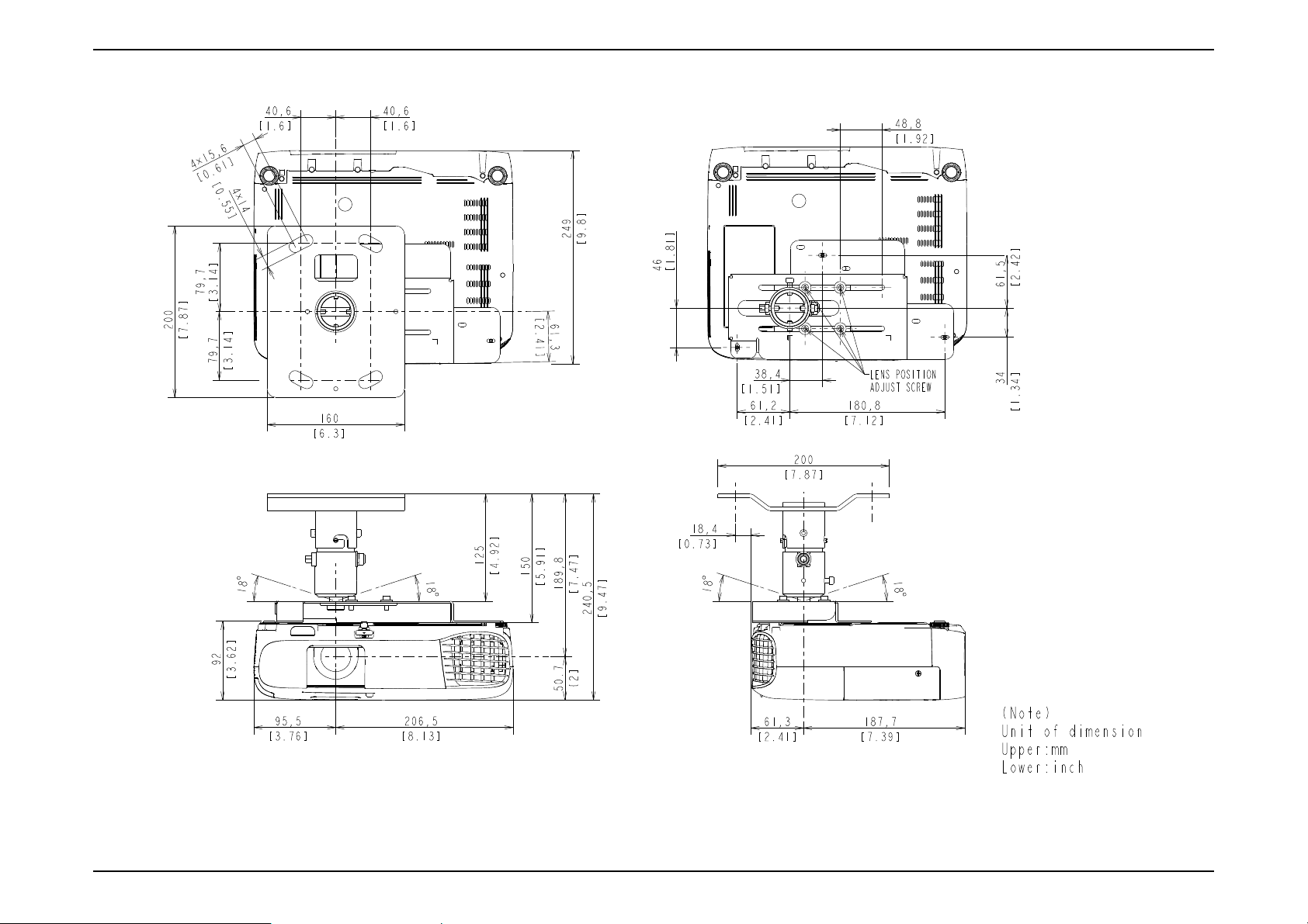
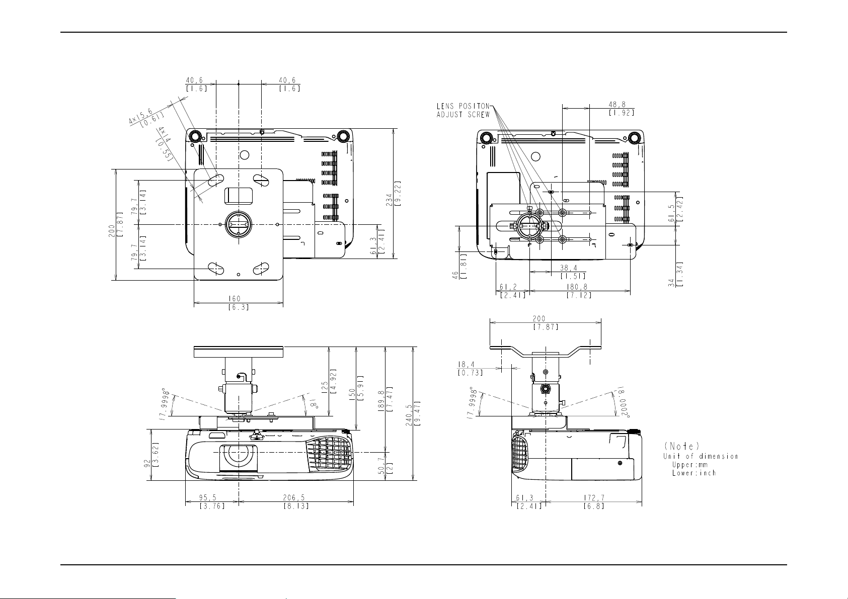
1.3 Dimensions
EB-EB-E01/X06/W06/E10/X51/W51
SEIKO EPSON 20 Revision A
Page 21
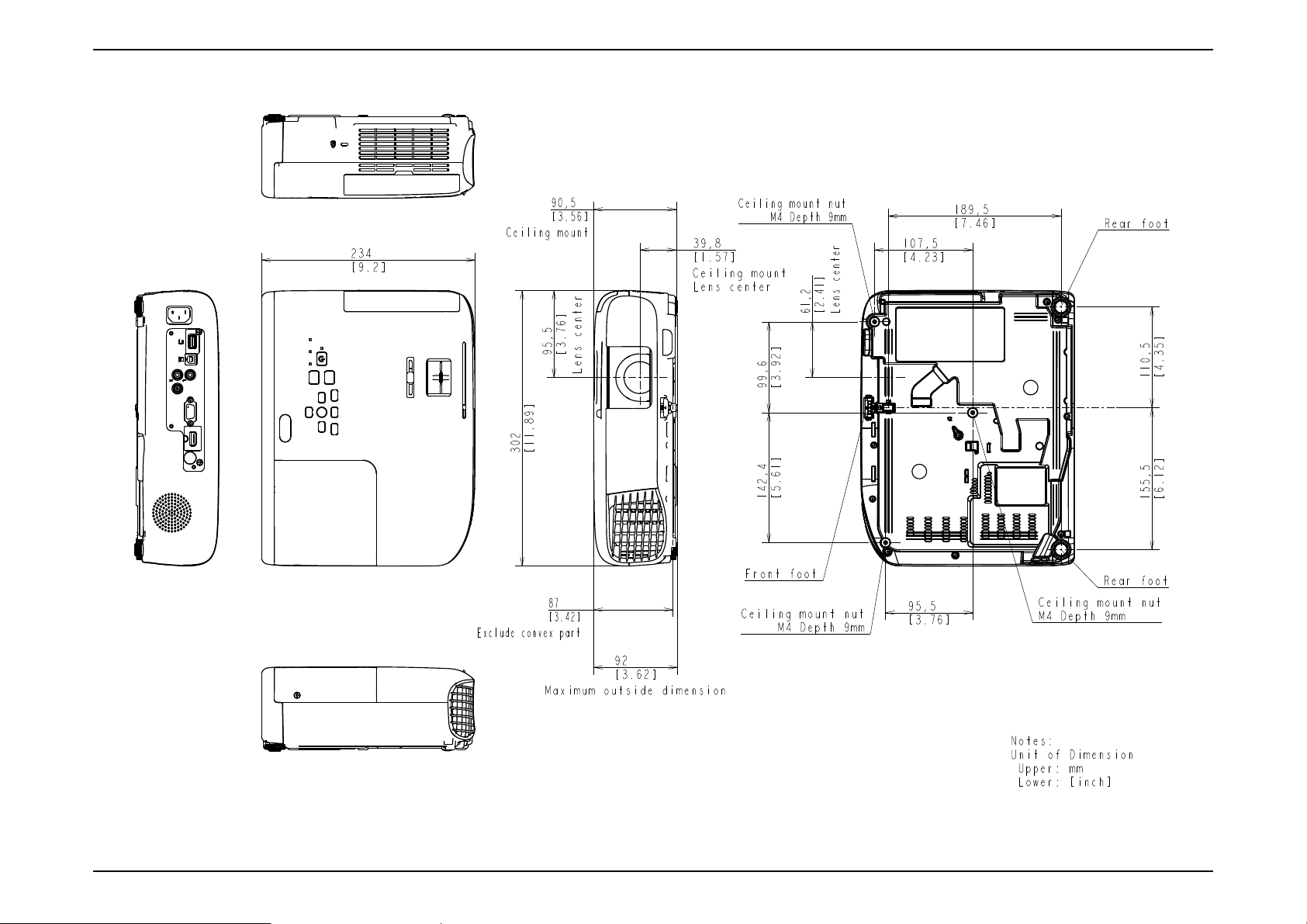
EB-E01 series Product Description INTERNAL USE ONLY
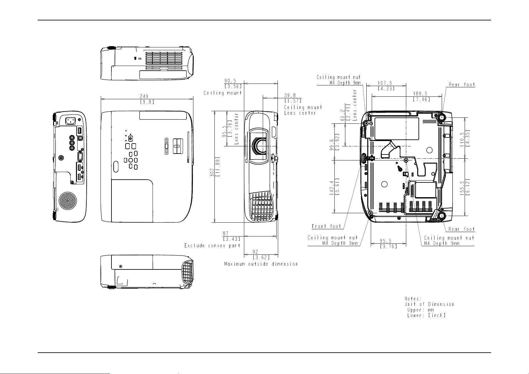
EB-FH06/E20/X49/W49/118, PL 119W, EH-TW740/TW750
SEIKO EPSON 21 Revision A
Page 22
EB-E01 series Product Description INTERNAL USE ONLY
EB-FH52/972/982W/992F
SEIKO EPSON 22 Revision A
Page 23
EB-E01 series Product Description INTERNAL USE ONLY
EB-W52
SEIKO EPSON 23 Revision A
Page 24
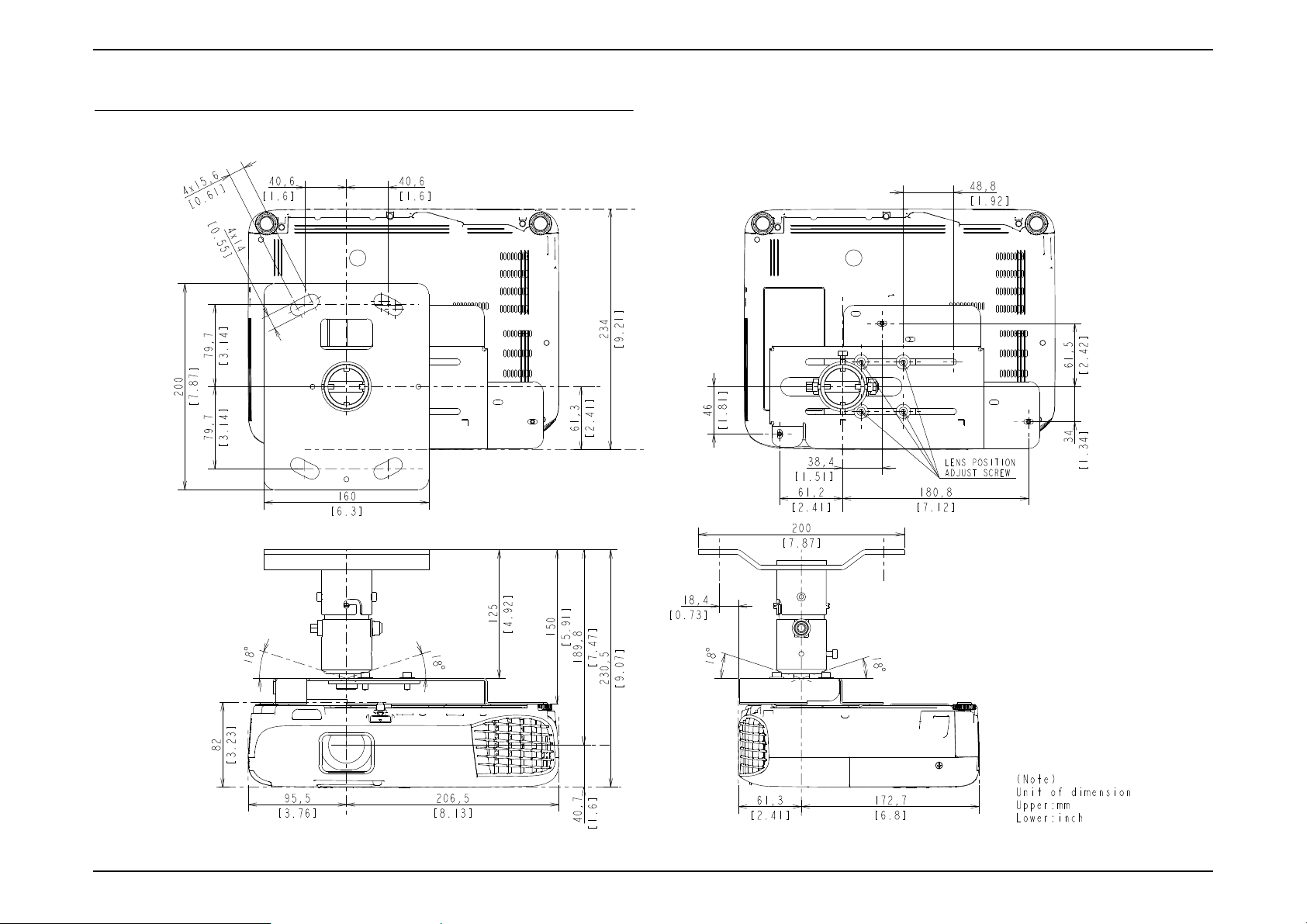
EB-E01 series Product Description INTERNAL USE ONLY
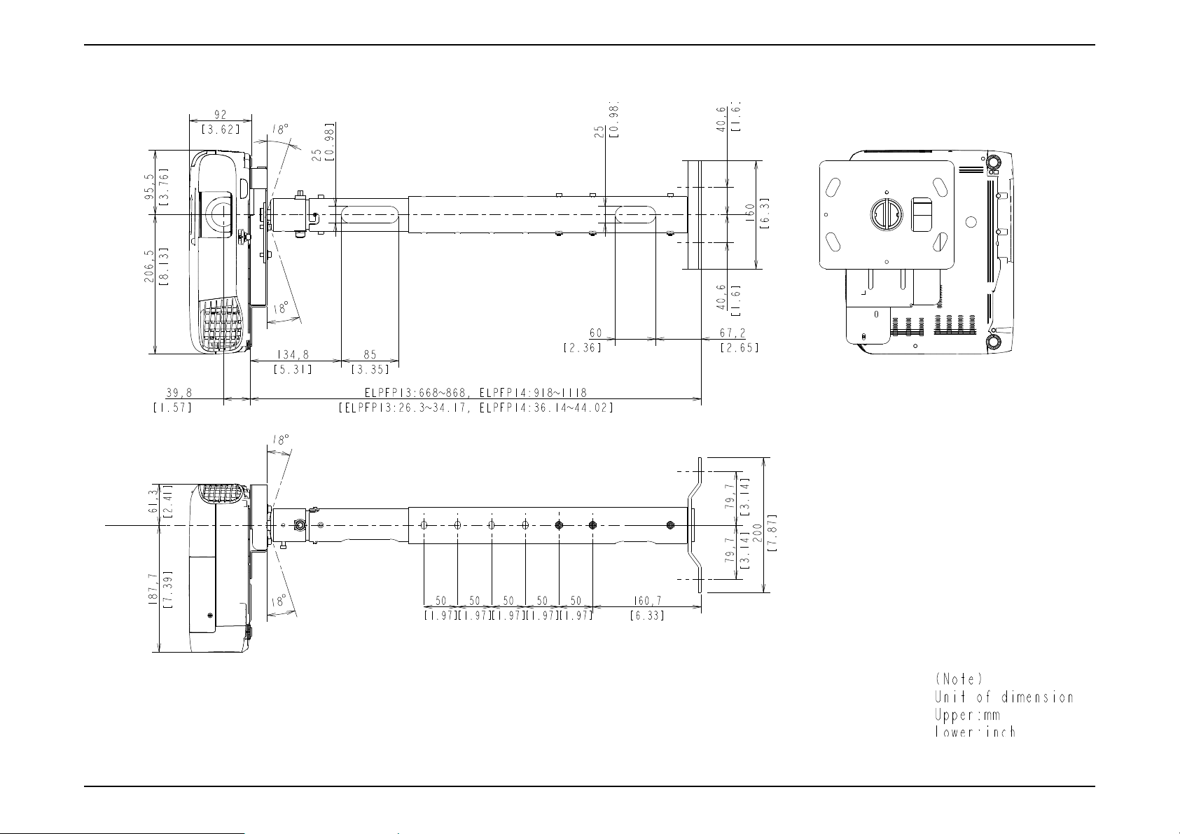
1.4 Ceiling Mount
EB-E01/X06/W06/E10/X51/W51 (ELPMB23)
SEIKO EPSON 24 Revision A
Page 25
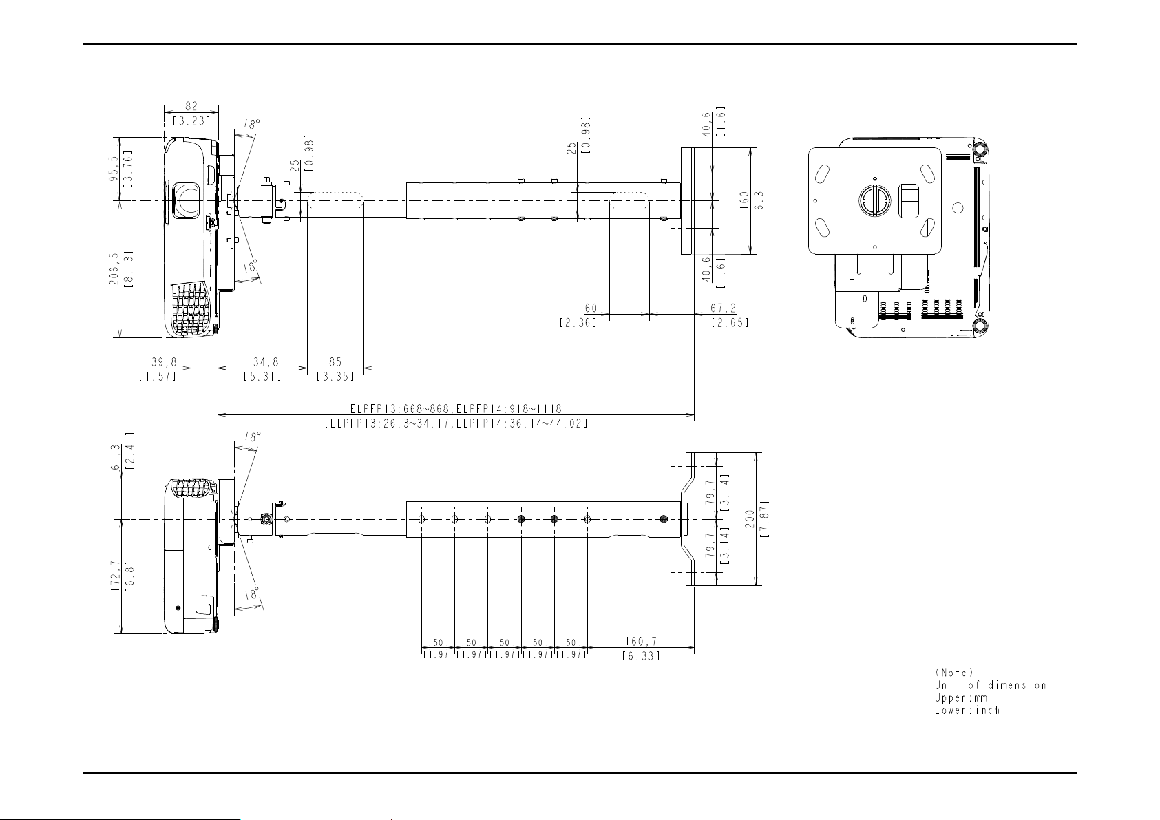
EB-E01 series Product Description INTERNAL USE ONLY
EB-E01/X06/W06/E10/X51/W51 (ELPMB23 + ELPFP13/ELPFP14)
SEIKO EPSON 25 Revision A
Page 26
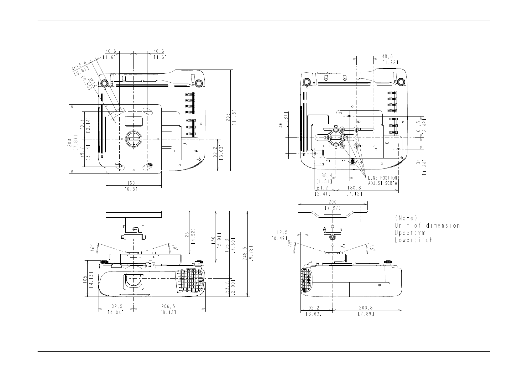
EB-E01 series Product Description INTERNAL USE ONLY
EB-FH06/E20/X49/W49/118, PL 119W, EH-TW740/TW750 (ELPMB23)
SEIKO EPSON 26 Revision A
Page 27
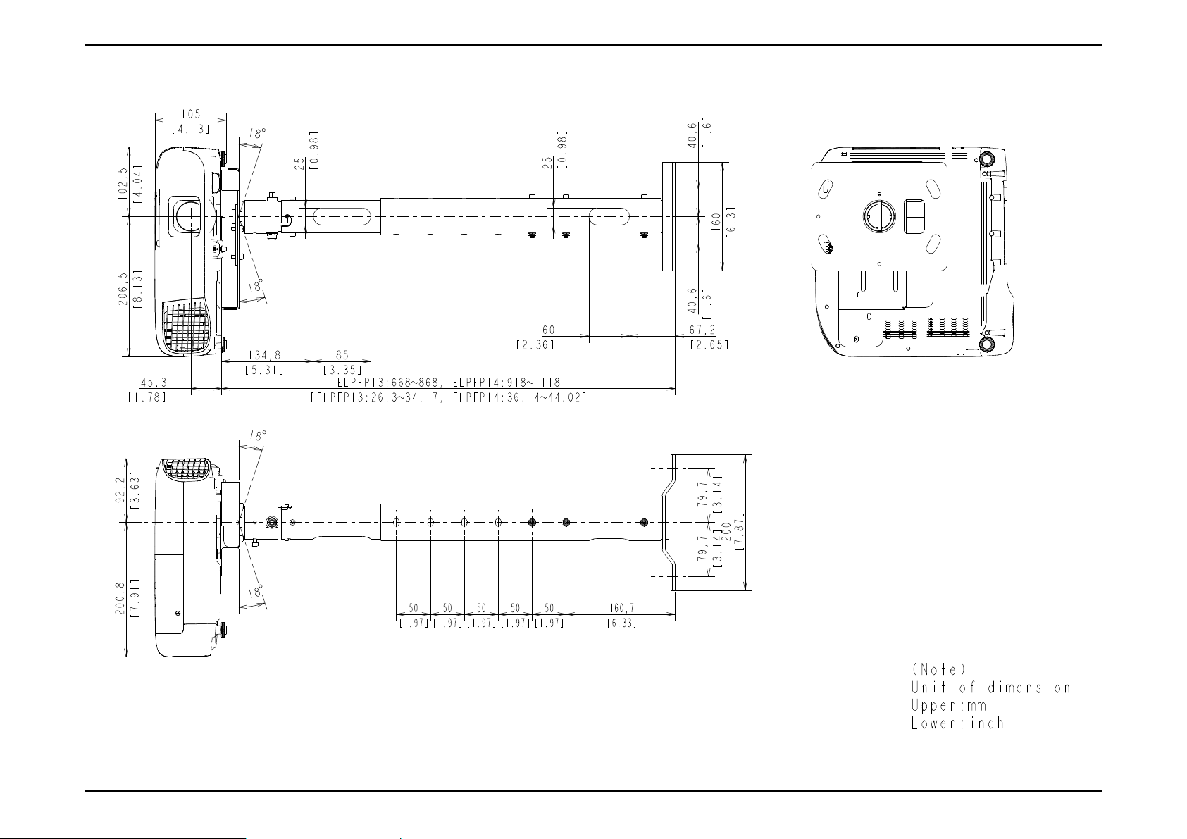
EB-E01 series Product Description INTERNAL USE ONLY
EB-FH06/E20/X49/W49/118, PL 119W, EH-TW740/TW750 (ELPMB23 + ELPFP13/ELPFP14)
SEIKO EPSON 27 Revision A
Page 28
EB-E01 series Product Description INTERNAL USE ONLY
EB-FH52/972/982W/992F (ELPMB23)
SEIKO EPSON 28 Revision A
Page 29
EB-E01 series Product Description INTERNAL USE ONLY
EB-FH52/972/982W/992F (ELPMB23 + ELPFP13/ELPFP14)
SEIKO EPSON 29 Revision A
Page 30
EB-E01 series Product Description INTERNAL USE ONLY
EB-W52 (ELPMB23)
SEIKO EPSON 30 Revision A
Page 31

EB-E01 series Product Description INTERNAL USE ONLY
EB-W52 (ELPMB23 + ELPFP13/ELPFP14)
SEIKO EPSON 31 Revision A
Page 32

TROUBLESHOOTING
CHAPTER
2
INTERNAL USE ONLY
Page 33

EB-E01 series Troubleshooting INTERNAL USE ONLY
2.1 Required Tools
The following tools are required in order to carry out troubleshooting of this
projector.
Name Qt. Application/Other
Projection screen 1 To project images on.
Genuine power cable 1
Genuine remote controller 1
Host computer 1 To output audio and video data to the projector*
PC cable 1
Video equipment 1
Audio and Video cables
(HDMI/Composite/USB, and
each audio)
Multi tester 1
Double-sided tape q.s.*
General tools 1 set Tools given in " 3.1.4 Tools (p66)".
RS-232C cable 1 For writing DR data
USB memory or USB cable 1 For USB Updater
IPS tool 1
CAT 1
Intra-mart 1
RESCUE 1
USB firmware for updater 1
EasyMP Network firmware for
updater
Microsoft .Net Framework 3.5
or later
USB COM Driver 1
*1: When repairing a wide panel (16:10) model, prepare the video source and devices
considering the full screen display of 16:10 aspect.
1 each
(To check the component video input)
To control service tools
To output audio and video data to the projector*
(To check the HDMI and composite video input)
To measure resistance values and voltages (AC/
DC).
2
To secure parts
See " 3.5.10 Service tool list (p150)".
1
1
1
1
*2: q.s.: Sufficient quantity
SEIKO EPSON 33 Revision A
Page 34

EB-E01 series Troubleshooting INTERNAL USE ONLY
Start
Is the projector
able to project the
Check the error name.
" 4.1.1 How To Display the AS (After
Service) Menu (p171)"
No
Yes
>> To the next page
Yes
Troubleshoot referring to
" 2.4 Troubleshooting from the Device
Names (p37)"
Does the LED Indicator flash
or turn on?
Has any error
occurred?
Check the error name.
" 4.1.2.3 Confirmation method using a USB
memory (p188)"
" 2.5.3 Troubleshooting without Error Indications (p47)"
Troubleshoot according to Troubleshooting at the time of
Power-ON.
No
Yes
No
Yes
Troubleshoot referring to " 2.5.2 Troubleshooting by
Error Names (p43)"
No
Device Name can be
checked?
Is the projector
able to project the image?
2.2 Troubleshooting Procedure
This chapter describes troubleshooting procedure starting from error messages/status to diagnose problems. Refer to the descriptions and remedies below to specify
the troubled part, and carry out the necessary repair or replacement.
SEIKO EPSON 34 Revision A
Page 35

EB-E01 series Troubleshooting INTERNAL USE ONLY
Are there any errors listed in
2.5.3 Troubleshooting without
Error Indications?
Troubleshoot
referring to " 2.5.3 Troubleshooting without Error Indications
(p47)".
No
Yes
Troubleshoot
referring to " 2.5.4 Troubleshooting on image abnormality
(p51)".
From the previous page >>
No
Yes
Are there any errors listed in
2.5.4 Troubleshooting on
Image Abnormality?
Finish
SEIKO EPSON 35 Revision A
Page 36

EB-E01 series Troubleshooting INTERNAL USE ONLY
2.3 Exterior Check
When repairing this product, carry out exterior check of the target parts/units as
necessary.
Target part Check items
Any damage/deformation/cracking due to external forces?
Upper Case
Rear Case
Control panel
Lamp Cover Unit
Projection Lens
Lower Case
Foot
AC Inlet
Interface
(Connector part)
Air Filter
Is it fixed to Lower Case correctly?
Any foreign object/dirt on IR receiver?
Any damage/deformation/cracking due to external forces?
Is it fixed to Lower Case and in the frame correctly?
Is it fixed to Upper Case correctly?
Are there any stuck buttons?
Do buttons work smoothly?
Is it fixed to Upper Case correctly?
Any damage on the latch to operate the Interlock SW? (Remove the
lamp cover unit and check it.)
Does FOCUS RING work smoothly?
Does Zoom Ring work smoothly?
Any dirt/scratches on the projection lens?
Any damage/deformation/cracking due to external forces?
Any foreign object/dirt on it?
Does Front Foot work smoothly to adjust height?
Does Rear Foot work smoothly to adjust height?
Any Foot Rubber detached?
Any deformation/discoloration on the connector/terminals?
Any damage on the socket?
Any deformation/discoloration on the connector/terminals?
Any foreign objects on the connectors/terminals?
Is it fixed correctly?
Is there any dirt or foreign substance on the filter?
(Remove the air filter and check it.)
Is there any dirt/foreign substance on the fan inside the filter?
Target part Check items
Any deformation/discoloration on it?
Lens Shutter
Lamp
Is it fixed to Upper Case correctly?
Does it work smoothly?
Any deformation/discoloration on the frame?
Any deformation/discoloration on the connector?
Any dirt on the glass surface?
SEIKO EPSON 36 Revision A
Page 37

EB-E01 series Troubleshooting INTERNAL USE ONLY
2.4 Troubleshooting from the Device Names
To display the device names, see " o Error Name/Warning Name/Device ID/Source Name List (p179)".
This section explains the troubleshooting mainly for the troubling parts identified using the error names and device codes displayed on the AS (after service) Menu
and the IPS tool to carry out their necessary repair. If a device code can be identified through the AS Menu or IPS tool, find the specific troubling part from the table
below.
When the troubling part can be identified, the blue-lettered parts with reference pages in the following table can be replaced in shorter ways than the ordinary
disassembling procedures.
COOLING SYSTEM COMPONENTS (FAN) P.58
Error Name (Error Code)
Device Name IPS tool Name used in the manual SPI Parts Name
Fan (FN)
(P.40)
Device Code
LV1 LV1 Fan CN1602 INT Fan FAN;SR7039-THT-H838
LMP LMP Fan CN1604 Lamp Fan FAN,LAMP
EX EX Fan CN1603 EX Fan(P.140) FAN;TB6035-NMB-H838
COOLING SYSTEM/SWITCH COMPONENTS (SENSOR) P.59
Error Name (Error Code)
Device Name IPS tool Name used in the manual SPI Parts Name
Thermistor (SE)
(P.40)
Cover Open (LC) --- ---
Device Code
LMP LMP TH CN1601 Lamp Thermistor(P.139)
AIR AIR TH CN1600 AIR thermistor
CN
CN
CN4
(SW Board)
Part Name
Part Name
PCB ASSY;H980TH-MP;PH
Lamp Switch SWITCH,LID LAMP;PH;2
SEIKO EPSON 37 Revision A
Page 38

EB-E01 series Troubleshooting INTERNAL USE ONLY
POWER SUPPLY P.61
Error Name (Error Code)
Thermistor (SE)
(P.40)
CIRCUIT BOARDS P.62
Error Name (Error Code)
Thermistor (SE)
(P.40)
Device Code
CN
Device Name IPS tool Name used in the manual SPI Parts Name
PS (1) PS TH ---
PS Ballast Assy PS BALLAST UNIT ASSY;H838;EP;PH2;5PB BA TH ---
PFC (1) PFC TH ---
Device Code
CN
Device Name IPS tool Name used in the manual SPI Parts Name
LV LV TH --- MA Board MA Board Assy;H9**;PH;AS
Part Name
Part Name
SEIKO EPSON 38 Revision A
Page 39

EB-E01 series Troubleshooting INTERNAL USE ONLY
1. Power indicator
2. Status indicator
3. Wireless LAN indicator
4. Lamp indicator
5. Temp indicator
2.5 Error Indication and Problem diagnosis
2.5.1 Troubleshooting based on LED Indications
This section describes the LED error indications and corresponding error
names and their remedies.
ON Blink OFF
INTERNAL ERROR
LED Status
Power Status Lamp
Temp
Wireless LAN
Corresponding error name Remedy Reference
I2C: I2C H/W Error
DR: DR Status H/W Error
RAM: RAM H/W Error
ROM: ROM H/W Error
IV: Inner Error (Video sub-processor
error)
Disconnect the AC cable once and reconnect it and turn the
power back on.
P.45
If the same error occurs after trying the remedy above, check the
error name and carry out the remedy referring to the reference on
the right column.
SEIKO EPSON 39 Revision A
Page 40

EB-E01 series Troubleshooting INTERNAL USE ONLY
FAN ERROR/SENSOR ERROR
LED Status
Power Status Lamp
Temp
Wireless LAN
Corresponding error name Remedy Reference
Fan: Fan Error
Thermistor: Sensor Error
HIGH TEMPERATURE ERROR/AIR FILTER FLOW REDUCTION ERROR
LED Status
Power Status Lamp
Temp
Wireless LAN
Corresponding error name Remedy Reference
Temp: High Temp Error
Check the connections between each fan/sensor and MA Board.
If any connection failure is found, correct it.
If the same error occurs when turning the power back on after
trying the remedy above, check the error name and carry out the
remedy referring to the reference on the right column.
1. Check the Air Filter's condition (dirt accumulation,
clogging). When clogging or similar is found, clean/
replace the filter.
2. If the same error occurs when turning the power
back on after trying the remedy above, check the
error name and carry out the remedy referring to the
reference on the right column.
P.44
P.44
SEIKO EPSON 40 Revision A
Page 41

EB-E01 series Troubleshooting INTERNAL USE ONLY
AUTO IRIS ERROR/POWER SUPPLY (BALLAST) ERROR
Power Status Lamp
LAMP ERROR
Power Status Lamp
LED Status
LED Status
Temp
Temp
Wireless LAN
Wireless LAN
Corresponding error name Remedy Reference
Auto Iris: Auto Iris Error
If the same error occurs after turning the power back on, check
the error name and carry out the remedy referring to the reference
on the right column.
Ballast: Power Supply (Ballast) Error
Corresponding error name Remedy Reference
Check if the Lamp Cover is
installed correctly.
If not, reinstall the Lamp Cover
correctly.
Cover Open: Lamp Cover open Error
Lamp: Lamp Error
Lamp On: Lamp Lit Error
Check if the Lamp is installed
correctly.
If not, reinstall the Lamp Cover
correctly.
Lamp Off: Lamp Failure
If the Lamp is not broken,
Take out the lamp and check if
the Lamp is cracked or
damaged.
reinstall it and turn the power
back on. If the error recurs,
replace the Lamp with a new
one.
P.45
P.43
SEIKO EPSON 41 Revision A
Page 42

EB-E01 series Troubleshooting INTERNAL USE ONLY
LED Status
Power Status Lamp
Temp
Wireless LAN
Corresponding error name Remedy Reference
Take out the lamp and check if
the Lamp is cracked or
damaged.
Air Filter condition
(dirt accumulation, clogging)
If the Lamp is cracked/
damaged,
replace it with a new one.
If clogging is found, clean or
replace the Air Filter.
Lamp: Lamp Error
Lamp On: Lamp Lit Error
Lamp Off: Lamp Failure
If the projector has been used at
a place where is 1500 meters or
higher above sea level:
After trying above remedies:
If the High altitude mode is
ON, set it to OFF.
If the same error occurs after
turning the power back on,
check the error name and carry
out the remedy referring to the
references on the right column.
P.43
SEIKO EPSON 42 Revision A
Page 43

EB-E01 series Troubleshooting INTERNAL USE ONLY
2.5.2 Troubleshooting by Error Names
To display the error names, see " o Error Name/Warning Name/Device ID/Source Name List (p179)".
This section explains the troubleshooting mainly for the troubling parts identified using the error names and device codes displayed on the AS (after service) Menu
and the IPS tool to carry out their necessary repair. If a device code can be identified through the AS Menu or IPS tool, find the specific troubling part from the table
below.
TROUBLESHOOTING FROM THE ERROR NAME ON LAMP ERRORS
Error name Description Faulty part/part name Cause Remedy
Lamp Lamp is broken. Replace Lamp. P.74
Lamp Lamp Burnt Out Error
Lamp On
Lamp Off
Lamp lit error
Lamp Failure
Air Filter Air Filter is clogging. Clean Air Filter. Replace it if not improved. P.73
Lamp Switch Lamp Switch is broken. Replace Lamp Switch. P.86
PS Ballast Assy PS Ballast Assy is broken. Replace PS Ballast Assy. P.122
Lamp is broken due to the following
reasons:
Lamp
Cracks on the arc tube
Replace Lamp. P.74
Blackening/whitening of the arc tube
Swelled arc tube
PS Ballast Assy PS Ballast Assy is broken. Replace PS Ballast Assy. P.122
Reference
SEIKO EPSON 43 Revision A
Page 44

EB-E01 series Troubleshooting INTERNAL USE ONLY
TROUBLESHOOTING FROM THE ERROR NAME ON COOLING SYSTEM ERRORS
*: You can identify the broken fan or sensor by checking the device names in the "AS Menu" or IPS tool. For details, see AS Menu: 5TH Page (p176). For the positions of each fan
and sensor, see COOLING SYSTEM COMPONENTS (FAN) (p58) and COOLING SYSTEM/ SWITCH COMPONENTS (SENSOR) (p59).
Error name Description Faulty part/part name Cause Remedy
Air Filter is clogging. Clean Air Filter. Replace it if not improved. P.73
Thermistor is broken. Replace the broken Thermistor.
TH Cable is not connected properly. Connect TH Cable correctly to MA Board.
TH Cable is broken. Replace the broken TH Cable.
Vent is deformed or blocked by foreign
bodies.
Intake or exhaust opening is blocked by
something
Elements for temperature control on MA
Board are broken.
TH Cable is not connected properly. Connect TH Cable correctly to MA Board. P.53
TH Cable is broken.
Blades are broken.
Revolutions of the fan has become
abnormal.
Dust is accumulated on the fan. Clean the foreign material off of the fan. ---
Elements for fan control on MA Board are
broken. (Circuit error)
Clean the vent to remove the foreign material. ---
Replace the parts with deformed vent.
Improve the installation status. (Place it away from the
wall or obstacles)
Remove the obstacle from the opening area. ---
If the error continues after carrying out the remedies
above, the related circuit on MA Board is broken, replace
MA Board Assy.
Replace Fan.
If the error continues after carrying out the remedies
above, the related circuit on MA Board is broken, replace
MA Board Assy.
Temp Overheat Error
Fan Fan Error
Air Filter
Thermistor
Thermistor Cable
Exterior Parts
Installation Not installed correctly.
Environment of usage
MA Board
LV1
LMP
MA Board
Fan
EX
Reference
P.119
P.132
P.53
P.89
P.136
---
P.100
P.119
P.121
P.132
P.100
SEIKO EPSON 44 Revision A
Page 45

EB-E01 series Troubleshooting INTERNAL USE ONLY
Error name Description Faulty part/part name Cause Remedy
FPC is not connected properly. Connect FPC correctly to MA Board. P.53
FPC is broken.
The thermistor mounted on the circuit
board is broken.
Thermistor is broken. Replace Thermistor.
TH Cable is not connected properly. Connect TH Cable correctly to MA Board.
TH Cable is broken. Replace the broken TH Cable.
The thermistor mounted on the main
circuit board is broken.
The thermistor mounted on the BA Unit is
broken.
Replace MA Board. P.100
Replace PS Ballast Assy. P.122
Thermistor Sensor Error
LV
LMP
LWR
PS(1)
PFC(1)
PB
Optical engine
Thermistor
PS Ballast Assy
TROUBLESHOOTING FROM THE ERROR NAME ON ELECTRIC CIRCUIT ERRORS
Error name Description Faulty part/part name Cause Remedy
RAM
Inner
I2C Internal error I2C
DR Internal error DR
IV Video sub-processor error
Auto Iris Auto Iris Error
Internal error
(RAM)
Internal error
(ROM)
RAM has become abnormal.
MA Board
Input AC power supply
Environment (Temperature of the
customer’s operating
environment)
MA Board MA Board is broken. Replace MA Board. P.100
Auto Iris Assy
Moving parts (Gears) of Auto Iris
Assy
Flash ROM is broken.
(The number of data rewrite times has
exceeded its limit)
MA Board is broken.
Instability of the input AC Power
Supply. (caused by an external factor)
Access timing error (occurs in a low
temperature environment (Y43series))
TH Cable is not connected properly. Connect TH Cable correctly to MA Board. P.39
TH Cable is broken.
Auto Iris Assy is broken.
Foreign material sticks on the part and
causes operation failure.
Replace MA Board. P.100
If not appropriate, request the customer to improve the usage
environment. (Refer to “Safety precautions” in the projector’s User's
Guide)
Replace the Auto Iris Assy. P.115
Remove the foreign material in between the gears. ---
Reference
P.119
P.132
Reference
SEIKO EPSON 45 Revision A
Page 46

EB-E01 series Troubleshooting INTERNAL USE ONLY
Error name Description Faulty part/part name Cause Remedy
PS Ballast Assy BA Unit is broken. Replace PS Ballast Assy. P.122
Ballast Power Supply (Ballast) Error
PS Cable
TH Cable is not connected properly. Connect TH Cable correctly to MA Board. P.53
TH Cable is broken. Replace the broken TH Cable. P.122
Reference
SEIKO EPSON 46 Revision A
Page 47

EB-E01 series Troubleshooting INTERNAL USE ONLY
2.5.3 Troubleshooting without Error Indications
This section provides troubleshooting procedures based on observed faults.
TROUBLESHOOTING AT POWER-ON
Error Status Faulty part/part name Cause Remedy
The projector cannot be turned on from
the Control Panel. (Power indicator lights
up blue, and power can be turned on
using the remote controller)
Projector is not turned on
(Power LED does not light blue)
Control panel cable (FFC)
Control panel Control panel is broken. Replace the control panel.
PS Ballast Assy
MA Board MA Board is broken. Replace MA Board. P.100
TROUBLESHOOTING ON IMAGE DISPLAY & QUALITY
Error Status Faulty part/part name Cause Remedy
No image is projected. (Lamp lights)
Focus cannot be adjusted.
Zoom cannot be adjusted.
Black part of image is reddish.
Black part of image is greenish.
Input video signal
MA Board Video Input terminal is broken. Replace MA Board. P.100
FOCUS RING FOCUS RING is broken. Replace FOCUS RING. P.116
Projection Lens (Optical Engine) Projection Lens is broken. Replace Optical Engine. P.113
Zoom Ring Zoom Ring is broken. Replace Zoom Ring. P.116
Projection Lens (Optical Engine) Projection Lens is broken. Replace Optical Engine. P.113
Optical engine
MA Board MA Board is broken. Replace MA Board. P.100
Optical engine
MA Board MA Board is broken. Replace MA Board. P.100
Reference
TH Cable is not connected properly. Connect TH Cable correctly to MA Board. P.39
TH Cable is broken. Replace the control panel.
TH Cable is not connected properly. Connect TH Cable correctly to MA Board. P.39
PS Ballast Assy is broken. Replace PS Ballast Assy. P.122
The selected input video cable is not
connected correctly.
FPC for L/V (R) is not connected
properly.
FPC for L/V (R) is broken. Replace Optical Engine. P.113
FPC for L/V (G) is not connected
properly.
FPC for L/V (G) is broken. Replace Optical Engine. P.113
Connect the selected input video cable correctly. ---
Connect FPC for L/V (R) to MA Board correctly. P.39
Connect FPC for L/V (G) to MA Board correctly. P.39
P.84
Reference
SEIKO EPSON 47 Revision A
Page 48

EB-E01 series Troubleshooting INTERNAL USE ONLY
Error Status Faulty part/part name Cause Remedy
Black part of image is bluish.
Abnormality can be seen on the projected
image.
Optical engine
MA Board MA Board is broken. Replace MA Board. P.100
Optical parts
TROUBLESHOOTING ON AUDIO INPUT/OUTPUT
Error Status Faulty part/part name Cause Remedy
Audio Input cables
Sound does not come out.
Speaker
IF Board
Reference
FPC for L/V (B) is not connected
properly.
FPC for L/V (B) is broken. Replace Optical Engine. P.113
Dirt or problems (deterioration,
misalignment, or looseness) of the optical
part(s)
TH Cable is not connected properly. Connect the audio input cable correctly.
TH Cable is broken. Replace the broken audio input cable.
TH Cable is not connected properly. Connect TH Cable correctly to MA Board. P.53
TH Cable is broken.
Speaker is broken.
Input terminal is broken.
Elements for audio control on IF Board
are broken. (Circuit error)
Connect FPC for L/V (B) to MA Board correctly. P.39
Replace Optical Engine. P.113
Reference
---
Replace Speaker.
If the error continues after carrying out the remedies
above, the related circuit on IF Board is broken, so
replace IF Board.
P.105
P.121
P.106
SEIKO EPSON 48 Revision A
Page 49

EB-E01 series Troubleshooting INTERNAL USE ONLY
TROUBLESHOOTING ON OPERATION ABNORMALITY
Error Status Faulty part/part name Cause Remedy
Operation using Remote Controller
cannot be made.
Projector cannot be operated from the
control panel.
LED does not light up
(Power can be turned on using remote
control.)
AV Mute does not function even if the
shutter is closed.
Remote Controller
Receiver (RC Filter)
Cable (IR Board)
IR Board
IF Board
Control panel cable (FFC)
SW Buttons SW Buttons are broken. Replace the SW Buttons.
SW Board SW Board is broken. Replace the SW Board.
MA Board
SW Board
MA Board
Lens Shutter Output Switch
Batteries ran out. Replace the batteries with new ones. ---
Remote Controller is broken. Replace Remote Controller. ---
The Lower Case or IF Case receiver is
dirty.
TH Cable is not connected properly.
TH Cable is broken. Replace the cables of the IR Board. P.136
Elements for remote control processing on
the IR Board are broken. (Circuit error)
Elements for remote control processing on
the IF Board are broken. (Circuit error)
TH Cable is not connected properly. Connect TH Cable correctly to MA Board.
TH Cable is broken. Replace the broken TH Cable.
Elements for operation processing on MA
Board are broken. (Circuit error)
TH Cable is not connected properly. Connect the cable to MA Board correctly. P.53
SW Board is broken. Replace the SW Board. P.84
Elements for LED display on MA Board
are broken. (Circuit error)
TH Cable is not connected properly. Connect the cable to SW Board correctly. P.87
Lens shutter output switch is broken. Replace the lens shutter output switch. P.87
Clean Lower Case or IF Case. Replace Lower Case or IF
Case if not improved.
Connect the cables of the IR Board to the MA Board
correctly.
If the error continues after carrying out the remedies
above, the circuit on the IR Board is broken, so replace
the IR Board.
If the error continues after carrying out the remedies
above, the related circuit on IF Board is broken, so
replace IF Board.
If the error continues after carrying out the remedies
above, the related circuit on MA Board is broken, so
replace MA Board Assy.
If the error continues after carrying out the remedies
above, the related circuit on MA Board is broken,
replace MA Board Assy.
Reference
P.77
P.136
P.53
P.136
P.106
P.84
P.100
P.100
SEIKO EPSON 49 Revision A
Page 50

EB-E01 series Troubleshooting INTERNAL USE ONLY
TROUBLESHOOTING ON OTHER ABNORMALITY
Error Status Faulty part/part name Cause Remedy
Smoke/Abnormal odor
Abnormal noises
Reference
Lamp Burn on foreign objects (dust) from heat.
Fan,Lamp Burn on cables from heat. Replace the burned cables or parts with new ones. P.122
PS Ballast Assy Burn on circuit board from heat. Replace PS Ballast Assy. P.122
PS Ballast Assy
Fan
Operating parts Screws are loose or fallen off. Tighten the screws or reassemble the parts. ---
Pulse transformer vibrates abnormally.
BA Unit vibrates abnormally.
Foreign material sticks on a fan. Clean the foreign material off of the fan.
Fan’s impeller is broken. Replace Fan.
Clean the area around Lamp to remove the foreign
objects.
Replace PS Ballast Assy. P.122
Check if one of the fans contacts with other parts. If so,
correct its installation.
P.74
P.37Fan is contacting other parts.
SEIKO EPSON 50 Revision A
Page 51

EB-E01 series Troubleshooting INTERNAL USE ONLY
2.5.4 Troubleshooting on image abnormality
The following tables present this projector’s possible troubles in image quality, and provides probable causes and troubleshooting procedures based on the observed
phenomena.
ILLUMINATION REDUCTION
Phenomenon Cause Remedy Reference
The projected image became darker.
Some optical parts might mist for some
reasons.
COLOR NON-UNIFORMITY
Phenomenon Cause Remedy Reference
Color non-uniformity can be seen partially in
the projected image.
Some optical parts may become
deteriorated.
Some optical parts may be broken.
Clean the parts with a cotton swab or
the like moistened with ethanol.
Replace the deteriorated or broken
parts with new ones.
Optical Engine Repair Service Manual
Optical Engine Repair Service Manual
SEIKO EPSON 51 Revision A
Page 52

EB-E01 series Troubleshooting INTERNAL USE ONLY
COLOR BANDING (SHADOW)
Phenomenon Cause Remedy Reference
There occur “shadows”* on the right and left
side.
* : * “Shadow” is a vertical color banding
appearing on the left or right side.
Some optical parts may be displaced due to
some shock or the like.
Re-assemble the defective parts.
If the phenomenon not improved,
replace the part with a new one. If
still not improved, replace the
Optical Engine.
Optical Engine Repair Service Manual
ABNORMAL IMAGE
Phenomenon Cause Remedy Reference
Some abnormality can be seen in the projected
image.
Some optical parts may be detached.
Re-assemble the defective parts. If
the phenomenon not improved,
replace the part with a new one.
Optical Engine Repair Service Manual
SEIKO EPSON 52 Revision A
Page 53

EB-E01 series Troubleshooting INTERNAL USE ONLY
CN1405
RTC Board
CN501
WFD Board 2
CN3000
PS Ballast Assy
CN8900
B L/V
CN8800
G L/V
CN8700
R L/V
CN1603
EX Fan
CN1604
Lamp Fan
CN701 (700/702)
Speaker
CN2200
Auto Iris Assy
CN1400
SW Board
CN1600
AIR-TH
CN1403
F-IR
CN1602
LV-FAN
CN500
WFD Board 1
CN1601
LMP-TH
Circuit Board Image
CN1800
W-LAN
2.5.5 Cable connection on the MA Board and error symptoms
This section describes the projector’s status when disconnection occurs somewhere between the parts/units and the MA Board. If any problem has occurred, refer to
the following table and check the doubted connectors are securely connected. If there is a disconnection or a loose connection, connect it correctly.
SEIKO EPSON 53 Revision A
Page 54

EB-E01 series Troubleshooting INTERNAL USE ONLY
MA
Board
Board-to-board
Air TH
RTC Board
SW Board
LMP TH
CN1600
CN1400
CN1405
CN1403
CN1602
CN501
CN3000
CN8800
CN701*
CN702*
CN8700 CN8900
CN2200
CN1603
CN500
CN1601
CN1604
IF Board
Speaker 5W*
EX Fan
WFD Board
PS Ballast Assy
WFD Board
P4Combo
Optical Engine
CN700*
Speaker 16W*
Lamp Fan
Auto Iris
Front IR
LV Fan
Indicates connector on the back side
* Speakers and connectors dif-
fer according to model.
CONNECTION DIAGRAM BETWEEN BOARDS
SEIKO EPSON 54 Revision A
Page 55

EB-E01 series Troubleshooting INTERNAL USE ONLY
Connector
No.
CN8700 Optical Engine (R L/V) --- ---
CN8800 Optical Engine (G L/V) --- ---
CN8900 Optical Engine (B L/V) --- ---
CN3000 PS Unit (P/S) --- ---
CN1600 AIR-TH Thermistor AIR
CN1601 LMP-TH Thermistor LMP
CN1602 LV-FAN Fan LV1
CN1603 EX-FAN Fan EX
CN1604 LMP-FAN Fan LMP
CN500*
CN501*
CN1405*
CN1800*
1
1
CN1400 SW Board Cover Open Lamp cover open error
CN1403 IR Board --- ---
1
2
Destination
WFD Module WFD WFD error
RTC Board I2C Internal error
P4Combo --- ---
Error Name/
Device Name
Name
Sensor Error
Fan Error
Error Information
Phenomenon
When pressing the power button, projection starts normally. But the black part of the
projected image is reddish.
When pressing the power button, projection starts normally. But the black part of the
projected image is greenish.
When pressing the power button, projection starts normally, then the projection starts.
But the black part of the projected image is bluish. (This phenomenon is not easily
recognized on Logo screen or No Signal screen; therefore try displaying the menu or
the like to check for it.)
When connecting the AC cable, the power LED does not light blue. The power button
does not work or power cannot turn on.
The power can turn on and after the status LED blinks in blue, temperature LED blinks
in orange. When pressing the power button, initialization starts normally but sensor
error occurs while initializing. Then LEDs indicate the error, and then the projector
turns into the abnormal stand-by status
The power can turn on and after the status LED blinks in blue, temperature LED blinks
in orange. When pressing the power button, initialization starts normally but sensor
error occurs while initializing. Then LEDs indicate the error, and then the projector
turns into the abnormal stand-by status
The power can turn on and Power LED lights blue. Projection starts normally when the
power button is pressed, but the WFD does not function.
The power cannot be turned on with the operation panel. However, the power can be
turned on with the remote controller. When the power is turned on, the fan rotates at
high speed and turns off after a short while. Then the machine goes into abnormal
stand-by mode after displaying Lamp Cover Open Error.
Operates normally after the power turns on. However, IR receiver at the front stops
working.
The power can turn on and Power LED lights blue. When pressing the power button,
initialization starts but instantly the projector changes to the Internal error mode. After
a certain period of cooling, the projector turns into the abnormal stand-by status. The
LED Indicator’s warning display continues until unplugging the AC cable.
The power can turn on and Power LED lights blue. Projection starts normally when the
power button is pressed, but the W-LAN does not function.
Reference
P.60
P.61
P.37
P.37
P.62
P.62
P.62
P.62
P.62
SEIKO EPSON 55 Revision A
Page 56

EB-E01 series Troubleshooting INTERNAL USE ONLY
Connector
No.
CN2200 Auto Iris Assy Auto Iris Auto Iris Error
CN700*
CN701*
CN702*
3
4
5
Destination
Speaker (2W)
Speaker (16W)
Speaker (5W)
Error Name/
Device Name
--- ---
Name
*1 EB-FH52/992F, EH-TW750
*2 EB-FH52/992F/W52, EH-TW750
*3 EB-E01/X06/W06/E10/X51/W51/W52
*4 EB-FH52/972/982W/992F/118, PL 119W
*5 EB-FH06/E20/X49/W49, EH-TW740/TW750
Error Information
Phenomenon
The power can turn on and Power LED lights blue. When pressing the power button,
initialization starts but instantly the projector changes to the Auto Iris Error mode. The
error message in Auto Iris is displayed on the screen, and it advises the user to turn off
the power and to contact the Epson Service. When pressing the power button, the LEDs
indicate the warning and after a certain period of cooling, the projector turns into the
abnormal stand-by status. The LED Indicator’s warning display continues until
unplugging the AC cable.
When pressing the power button, initialization starts normally and the projection starts.
However, no sound is output from the speaker even if the audio input is applied. Audio
controller on screen display appears, but no sound is output from the speaker even if
the audio input is applied.
Reference
P.60
P.62
SEIKO EPSON 56 Revision A
Page 57

EB-E01 series Troubleshooting INTERNAL USE ONLY
SW Board
Connector
No.
CN1 MA Board (CN1400) Cover Open Lamp cover open error
CN2* H Key ASSY --- ---
CN3* Lens Cover SW SH Shutter error
CN4 Lamp Cover SW Cover Open Lamp cover open error
Destination
Error Name/
Device Name
Name
* Not for EB-E01/E10
Error Information
Phenomenon
The power cannot be turned on with the operation panel. However, the power can be
turned on with the remote controller. When the power is turned on, the fan rotates at
high speed and turns off after a short while. Then the machine goes into abnormal
stand-by mode after displaying Lamp Cover Open Error.
Operates normally after the power turns on, but the lateral strain of the projected image
cannot be corrected.
The power can turn on and Power LED lights blue. When pressing the power button,
initialization starts normally and the projection starts. But the lamp does not turn off
even when the shutter is closed, and the AV mute does not function. (However, AV
mute on the remote controller works normally)
Note) Please note that this error may cause troubles such as deformation of the shutter
if it is kept closed.
When the power is turned on, the machine goes into abnormal stand-by mode after
displaying Lamp Cover Open Error.
Reference
P.62
P.62
P.59
P.59
SEIKO EPSON 57 Revision A
Page 58

EB-E01 series Troubleshooting INTERNAL USE ONLY
Lamp Fan (P.120)
INT Fan (P.132)
EX Fan (P.119)
2.6 Parts Layout Diagrams
COOLING SYSTEM COMPONENTS (FAN)
SEIKO EPSON 58 Revision A
Page 59

EB-E01 series Troubleshooting INTERNAL USE ONLY
LMP Thermistor (TH Board) (P.119)
Air Thermistor (TH Board) (P.132)
Lens Shutter Output Switch
(Switch Cable H721-A) (P.87)
Lamp Output Switch
(Lid Lamp Switch) (P.86)
COOLING SYSTEM/ SWITCH COMPONENTS (SENSOR)
SEIKO EPSON 59 Revision A
Page 60

EB-E01 series Troubleshooting INTERNAL USE ONLY
Auto Iris Assy (P.115)
Optical Engine (Assy) (P.113)
Lamp Assy (P.74)
OPTICAL PARTS
SEIKO EPSON 60 Revision A
Page 61

EB-E01 series Troubleshooting INTERNAL USE ONLY
PS Ballast Assy (P.122)
Filter Board (P.135)
POWER SUPPLY
SEIKO EPSON 61 Revision A
Page 62

EB-E01 series Troubleshooting INTERNAL USE ONLY
Speaker (P.105) (P.121)
MA Board (P.100)
Control Panel (P.84)
IF Board (P.106)
P3dash Module (P.96)
WFD Board (P.94)
IR Board (P.131) (P.136) P4combo Module (P.128)
RTC Board (P.97)
H KEY ASSY (P.86)
RTC Board (EH-TW750) (P.112)
CIRCUIT BOARDS
SEIKO EPSON 62 Revision A
Page 63

DISASSEMBLY AND ASSEMBLY
CHAPTER
3
INTERNAL USE ONLY
Page 64

EB-E01 series Disassembly and Assembly INTERNAL USE ONLY
3.1 Precautions
This section describes cautions before starting disassembling and
assembling this product. Make sure to read the precautions below before
starting.
3.1.1 General Cautions in operation
General cautions for disassembling and assembling this product are
provided below. Cautions for each procedure are provided in its
corresponding section. Make sure to refer to them before starting.
Do not touch the lamp or the parts around it. They are extremely hot
even after the cooling down operation completed. If any maintenance
work inside the projector is necessary soon after the projector is in
operation, leave the unit until it becomes cool enough before performing
maintenance work.
Never use the air blowers such as a lens cleaner that contains flammable
gas in repair/maintenance work.
Do not disassemble any components not as specified in this Service
Manual.
The Optical Engine, the circuit boards are very sensitive to static
electricity; therefore, be sure to take appropriate measures to prevent
static destruction such as to place them inside static-proof bags once they
have been removed from the projector.
The Optical Engine is very sensitive to vibration and shocks; therefore,
make sure to handle it with care.
The speaker unit contains a permanent magnet; therefore, make sure to
keep it away from any storage media such as floppy disks or magnetic
cards.
Be careful not to drop a metal part such as a screw, a washer, or a clip
into the inside of the product. If such cases should occur accidentally,
never turn on the power supply until all the dropped parts are found and
removed.
When carrying out any of the following operations, check that there is no
dust or dirt on any component or on any glass surface before installation.
If any contamination is found, clean it off using isopropyl alcohol.
Optical Engine removal
Lamp removal
When the projector is disassembled, the dust in and around parts (such
as those on the fans or air filter) may get transferred to other parts such
as the R, G and B light valves which are the central part of the display
mechanism. This may have an adverse effect on the quality of projected
images. Be sure to check whether any of the parts are dusty or dirty, and
use a vacuum cleaner to clean them first before carrying out disassembly/
reassembly work.
After reassembling the product, check the following before turning the
power on. All the parts and screws are installed and secured to the
proper positions. No cables are caught in the metal frames.
For this projector, a calibration is performed for the “Screen Fit”
function at the factory shipment. If the “MA Board (Assy)” or later in the
flowchart is disassembled for repair, the adjusted values may be
misaligned; therefore, restart the projector and check for abnormalities
in the functionality or the projected image.
SEIKO EPSON 64 Revision A
Page 65

EB-E01 series Disassembly and Assembly INTERNAL USE ONLY
Disassembly
Disassemble the product
following the given instructions.
Repair/Maintenance
Perform parts replacement and
cleaning, etc.
Reassembly
Unless otherwise specified,
reassembly is the reverse of the
disassembly procedure.
Finish
Safety Check after servicing
Refer to "3.5.1 Safety Check after
servicing (P.142)", and carry out
the required safety checks
When carrying out repair or
maintenance of a safety device
3.1.2 Precautions
The precautions given below must be always observed whenever
disassembling/reassembling the projector to ensure the safety of service
personnel and maintain the quality.
Do not wear the metal products such as a wrist watch, cuff buttons, rings,
tie-pin etc. to avoid getting into an unsafe state due to touching the
projector.
When disassembling/assembling the projector, be sure to turn off the
power switch and pull out the power cable from the projector
beforehand.
When disassembling/assembling the projector, be sure to wear the gloves
and static discharge equipment such as an anti-static wrist strap and a
mat.
When replacing the circuit component such as a board or the optical
engine, be sure to contact the anti-static case containing the new one to
the metal part of this product before taking it out.
Disconnect all the interface cables from the projector.
Before disassembling the projector, make sure to clean dust or dirt on the
air filter, the interface section and outer cases using a vacuum cleaner or
the like.
When treating the non-after-service-parts as an assembly in this section,
they are indicated by "(Assy)".
(Example: "Case Lower (Assy)")
3.1.3 Workflow
SEIKO EPSON 65 Revision A
Page 66

EB-E01 series Disassembly and Assembly INTERNAL USE ONLY
3.1.4 Tools
The following table indicates the tools recommended for use for disassembly,
reassembly and adjustment.
3.1.4.1 Tool List
Tool Name Qt.
Phillips screwdriver No. 00
(8 cm)
Phillips screwdriver No. 1
(10 cm)
Phillips screwdriver No. 2
(10 cm)
Hexagonal box screwdriver
(5 mm)
Flat-head precision screwdriver 1 Disassembling the Front Foot
Gloves 1
Anti-static wrist band 1
Tweezers 1
Polyimide tape q.s.*
Brush 1
Vacuum cleaner 1
Lens cleaner
(nonwoven cloth)
Lubricant*
Projection screen 1
Genuine power cable 1
Genuine remote controller 1
Insulation ohmmeter for
insulation resistance test
2
q.s.*
q.s.*
1
1
1
1
1
1
1
1
Availability
Application
Disassembling the Focus Ring
and the zoom ring.
Disassembling the outer cases
and inner components.
Disassembling the outer cases
and inner components.
Removing the computer
interface
Be sure to wear them when
handling circuit boards or
Optical Engine.
Securing cables.
Use commercially available
Polyimide tape generally called
“KAPTON
Cleaning away dust.
Cleaning away dust.
Cleaning the projection lens.
Lubricating the shutter and its
frame.
To project images on.
Rating: 500 V/100 MW
®
TAPE”.
Tool Name Qt.
Multi meter 1
Air compressor or hand blower 1
Host computer 1
PC cable 1
Video equipment 1
Audio and Video cables
(HDMI/Composite/USB, and
each audio)
Multi tester 1
RS-232C cable 1
USB memory or USB cable 1
IPS tool 1
CAT 1
Intra-mart 1
RESCUE 1
USB firmware for updater 1
EasyMP Network firmware for
updater
Microsoft .Net Framework 3.5
or later
USB COM Driver 1
*1: q.s.: Sufficient quantity
*2: Usable item = “Grease G-78 (AQUADRY W-0082)”
1 each
Availability
1
1
3.1.4.2 Recommended Tool List
Tool Name Qt.
Screwdriver magnetizer 1
Availability
Application
Ground continuity check
To remove dusts from optical
parts and air filter.
To output audio and video data
to the projector (To check the
component video input).
To control service tools
To output audio and video data
to the projector (To check the
HDMI input).
To measure resistance values
and voltages (AC/DC).
For writing DR data
For USB Updater.
See " 3.5.10 Service tool list
(p150)".
Application
To prevent the screw from
falling into the projector
SEIKO EPSON 66 Revision A
Page 67

EB-E01 series Disassembly and Assembly INTERNAL USE ONLY
Lock
Lock
Lock
3.1.5 How to unlock connectors for FFC/FPC
Type Locked Unlocked How to unlock connectors
Slide-open type
(upward) #1
Slide-open type
(upward) #2
Slide-open type
(toward FFC)
Slide the lock (black) upward to the FFC to unlock it.
Slide the lock (light brown) upward to the FFC to unlock it.
Slide the lock (ivory) toward the FFC to unlock it.
SEIKO EPSON 67 Revision A
Page 68

EB-E01 series Disassembly and Assembly INTERNAL USE ONLY
Lock
Lock
Lock
P
U
S
H
Type Locked Unlocked How to unlock connectors
Flip-open type
(FPC)
Flip-open type
(Wide FPC)
Push-open type
Flip up the lock (black) on the connector opposite to the FPC to unlock it.
Flip up the lock (ivory) on the connector opposite to the FPC to unlock it.
[CAUTION] DO NOT mistake the black part of the connector for the lock
because it looks like a lock. Flipping up the black part will damage the
connector.
Press and hold the metal plate with a "PUSH" inscription, and disconnect the
FFC.
SEIKO EPSON 68 Revision A
Page 69

EB-E01 series Disassembly and Assembly INTERNAL USE ONLY
Lock
Lock
Type Locked Unlocked How to unlock connectors
Flip-open type
(FPC)
Slide-open type
(toward FFC)
Flip up the lock (black) of the FFC to unlock it.
Slide the lock (black) to the FFC to unlock it.
SEIKO EPSON 69 Revision A
Page 70

EB-E01 series Disassembly and Assembly INTERNAL USE ONLY
3.2 Flowchart
EB-E01/X06/W06/FH06/E10/X51/W51/FH52/E20/X49/W49/972/982W/992F/W52/118_EH-TW740/TW750_PL 119W The general disassembly procedure for
the projector is illustrated in the flowchart below. Unless otherwise specified, all reassembly should becarried out by following the disassembly procedures in
reverse, therefore reassembling procedures are omitted.
The part names in this chapter are written as abbreviations. See 3.9 Part Names List (p166) for the names of the after service parts in the SPI
(Service Parts Information).
The parts in colored boxes are target parts in their category. They are explained in details in the corresponding sections so as to reach the
parts in the shortest way.
The parts in gray boxes are those which are required to be removed to reach the target parts.
3.2.1 Standard operation time
The standard operation time for each operation is provided on the flowchart. Use the time as a guideline for actual operations.
Basis for the standard operation time
A service employee would have sufficient knowledge for the target product’s structure, and be able to disassemble/reassemble the product without any
reference to guide books.
Each operation time is the total time of disassembling/reassembling the target part following the given shortest procedure, and reassembling it.
SEIKO EPSON 70 Revision A
Page 71

EB-E01 series Disassembly and Assembly INTERNAL USE ONLY
Standard
operation time
(minutes)
-
1
4
8
9
10
11
13
14
18
20
A
Start
3.3.3 Front Foot (p75)
3.3.6 Upper Case
(Assy) (p80)
Housing/
consumables
Boards/
Optical parts
Cooling system
parts
Assembly
(not ASP)
Parts that should be removed
before removing target parts
[Items and colors]
3.3.2 Lamp (p74)
3.3.10 MA Board Assy
(p100)
Fastest way
Fastest way flowchart for 3.4 Shortest removal
procedures of identified failed parts (p137)
Typical Disassembly Flowchart
3.3.1 Air Filter (p73)
3.3.8 P3dash Module
(p96)
3.3.7 WFD Board
(p94)
3.3.5 Rear Case (p77)
3.3.10.1 Speaker 16W
(p105)
3.4.4 EX Fan (p140)
Fastest way
3.3.6.2 H Key Assy/
Upper Case (p86)
3.3.6.1 SW Board
(p84)
3.3.4 Rear Foot (p76)
3.3.6.4 Upper Case
(p89)
3.3.8 P3dash Module
(p96)
3.3.9 RTC Board
(p97)
3.3.6.3 Shutter (p87)
3.3.9 RTC Board
(p97)
B
3.4.1 Speaker (p137) 3.4.2 IR Board (p138) 3.4.3 LMP Thermistor
(p139)
3.3.15 P4combo
Module (p128)
(>> 72)
SEIKO EPSON 71 Revision A
Page 72

EB-E01 series Disassembly and Assembly INTERNAL USE ONLY
Standard
operation time
(minutes)
22
24
26
27
28
30
31
34
35
36
38
39
A
3.3.11 Optical Engine
(Assy) (p113)
3.3.12 EX Duct (Assy)
(p118)
3.3.13 Lamp Fan
(Assy) (p120)
3.3.17 Filter Boards
(p135)
3.3.18 Lower Case/IR
Board (p136)
3.3.11.1 Auto Iris Assy
(p115)
3.3.11.2 Focus Ring/
Zoom Ring (p116)
3.3.13.1 Lamp Fan/
Speaker 5W (p121)
3.3.14 PS Ballast Assy
(p122)
3.3.12.1 EX Fan/TH
Board (p119)
3.3.16.2 INT Fan/TH
Board (p132)
3.3.10.2 IF Board
(p106)
B
3.3.12 EX Duct (Assy)
(p118)
3.3.13 Lamp Fan
(Assy) (p120)
3.3.16 INT Duct
(Assy) (p129)
3.3.16.1 IR Board
(p131)
(>> 71)
SEIKO EPSON 72 Revision A
Page 73

EB-E01 series Disassembly and Assembly INTERNAL USE ONLY
Air Filter Assy
Air Filter Cover
Air Filter Cover Band*
* EB-E20/X49/W49/972/982W/992F/118, PL 119W
3.3 Disassembly and Assembly
The part names in this chapter are written as
abbreviations.
3.3.1 Air Filter
DISASSEMBLY PROCEDURE
1. Remove the "Air Filter Cover".
2. Remove the "Air Filter Assy".
See 3.9 Part Names List (p166) for the names of the after
service parts in the SPI (Service Parts Information).
EB-E20/X49/W49/972/982W/992F/118, PL 119W
If the "Air Filter Cover Band" is removed from the "Air
Filter Cover", the end of the band will be deformed and the
fixing force will be reduced. When reassembling, be sure to
replace the "Air Filter Cover Band" with a new one.
SEIKO EPSON 73 Revision A
Page 74

EB-E01 series Disassembly and Assembly INTERNAL USE ONLY
Lamp Assy
SCREW,LAMP;3X6
Lamp Cover
3.3.2 Lamp
DISASSEMBLY PROCEDURE
1. Loosen the screw ( ) and remove the "Lamp Cover".
2. Loosen the two screws and remove the "Lamp Assy".
SEIKO EPSON 74 Revision A
Page 75

3.3.3 Front Foot
Front Foot
DISASSEMBLY PROCEDURE
1. Insert a flat-head precision screwdriver or tweezers into the grooves on
2. Pull out the "Front Foot" to remove it.
EB-E01 series Disassembly and Assembly INTERNAL USE ONLY
both sides to release the hook.
SEIKO EPSON 75 Revision A
Page 76

EB-E01 series Disassembly and Assembly INTERNAL USE ONLY
Back side
Back side
Foot Rubber
Rear Foot
3.3.4 Rear Foot
DISASSEMBLY PROCEDURE
1. Turn the "Rear Foot" counterclockwise fully.
2. Slowly turn the "Rear Foot" until it clicks, and pull it off.
3. Remove the "Foot Rubber" from the "Rear Foot".
Be sure to align the mark on the bottom as shown in below,
and pull it off where it clicks.
(To align the groove on the LOWER CASE to prevent two
hooks of the screws from damaging.)
SEIKO EPSON 76 Revision A
Page 77

EB-E01 series Disassembly and Assembly INTERNAL USE ONLY
Rear Case
C.B.SCREW,3X8,F/NI
C.B.SCREW,3X6,F/ZB-3C
C.B.P-TITE SCREW,2.5X10,F/ZN-3C
RCR Filter
3.3.5 Rear Case
DISASSEMBLY PROCEDURE
EB-E01/X06/W06/E10/X51/W51
1. Remove the four screws ( ), the three screws ( ) or the one screw ( ),
and remove the "Rear Case".
2. Remove the "RCR Filter" from the "Rear Case".
Screws
SEIKO EPSON 77 Revision A
Page 78

EB-E01 series Disassembly and Assembly INTERNAL USE ONLY
Rear Case
IF Label
C.B.SCREW,3X8,F/NI
C.B.SCREW,3X6,F/ZB-3C
C.B.P-TITE SCREW,2.5X10,F/ZN-3C
EB-FH06/FH52/E20/X49/W49/972/982W/992F/118, PL 119W,
EH-TW740/TW750
1. Remove the four screws ( ), the six screws ( ) or the one screw ( ), and
remove the "Rear Case".
2. Remove the "IF Label" from the "Rear Case".
Screws
Be careful at the time of assembly, as the two clasps of the
"Rear Case" may break.
SEIKO EPSON 78 Revision A
Page 79

Rear Case
RCR Filter
C.B.SCREW,3X6,F/ZB-3C
C.B.P-TITE SCREW,2.5X10,F/ZN-3C
EB-E01 series Disassembly and Assembly INTERNAL USE ONLY
EB-W52
1. Remove the five screws ( ) and the two screws ( ), and remove the
"Rear Case".
2. Remove the "RCR Filter" from the "Rear Case".
Screws
SEIKO EPSON 79 Revision A
Be careful at the time of assembly, as the two clasps of the
"Rear Case" may break.
Page 80

EB-E01 series Disassembly and Assembly INTERNAL USE ONLY
C.B.P-TITE SCREW,2.5X10,F/ZN-3C
3.3.6 Upper Case (Assy)
DISASSEMBLY PROCEDURE
EB-E01/X06/W06/FH06/E10/X51/W51/W52/E20/X49/W49/118,
PL 119W, EH-TW740/TW750
1. See Flowchart (p70) and remove all parts up to the component below from
the projector.
Rear Case (p77)
2. Remove the six screws ( ) on the bottom.
Screws
SEIKO EPSON 80 Revision A
Page 81

EB-E01 series Disassembly and Assembly INTERNAL USE ONLY
Upper Case (Assy)
SW Cable
C.P.(S-P1)SCREW,2.5X6,F/ZN-3C
C.B.P-TITE SCREW,2.5X10,F/ZN-3C
3. Remove the three (four) screws ( / ) from the top.
(EB-118 and PL 119W have the screws)
Be careful as the FFC "SW Cable" is connected to the
switch board on the INT Duct side of the main unit.
4. Remove the FFC, and then remove the "Upper Case (Assy)".
(See How to unlock connectors for FFC/FPC (p67))
Screws
SEIKO EPSON 81 Revision A
Page 82

EB-E01 series Disassembly and Assembly INTERNAL USE ONLY
C.B.P-TITE SCREW,2.5X10,F/ZN-3C
EB-FH52/972/982W/992F
1. See Flowchart (p70) and remove all parts up to the component below from
the projector.
Rear Case (p77)
2. Remove the seven screws ( ) on the bottom.
Screws
SEIKO EPSON 82 Revision A
Page 83

EB-E01 series Disassembly and Assembly INTERNAL USE ONLY
Upper Case (Assy)
SW Cable
C.P.(S-P1)SCREW,2.5X6,F/ZN-3C
C.B.P-TITE SCREW,2.5X10,F/ZN-3C
3. Remove the four screws ( / ) from the top.
Be careful as the FFC "SW Cable" is connected to the
switch board on the INT Duct side of the main unit.
4. Remove the FFC, and then remove the "Upper Case (Assy)".
(See How to unlock connectors for FFC/FPC (p67))
Screws
SEIKO EPSON 83 Revision A
Page 84

EB-E01 series Disassembly and Assembly INTERNAL USE ONLY
SW Board
SW Cable
LED Lens
SW Button
Power Button
C.C.P-TITE SCREW,2X6.5,F/ZB-3C
3.3.6.1 SW Board
DISASSEMBLY PROCEDURE
1. See Flowchart (p70) and remove all parts up to the component below from
the projector.
Upper Case (Assy) (p80)
2. Remove the five screws ( ) and remove the "SW Board".
3. Remove the connector of the connected cable.
4. Remove the following parts:
SW Cable
(See How to unlock connectors for FFC/FPC (p67))
LED Lens
SW Button
Power Button
When attaching the "SW Board", fasten the screws in the
order shown below.
③
④
①
②
⑤
SEIKO EPSON 84 Revision A
Page 85

EB-E01 series Disassembly and Assembly INTERNAL USE ONLY
50°±5°
50°±5°
Fold the "SW Cable" as shown in this figure.
Route the cable connected to the SW Board as shown in this figure.
EB-FH52/972/982W/992F
EB-X06/W06/FH06/X51/W51/W52/E20/X49/W49/118,
PL 119W, EH-TW740/TW750
SEIKO EPSON 85 Revision A
Page 86

EB-E01 series Disassembly and Assembly INTERNAL USE ONLY
Lid Lamp Switch
Nut Plate M3
H Key Assy
Upper Case
Nut Plate M3
(EB-E01/X06/W06/E10/X51/W51)
C.P.F.TYPE1 P-TITE SCREW,1.6X8,F/ZN-3C
C.B.P-TITE SCREW,2.5X8,F/ZN-3C
3.3.6.2 H Key Assy/Upper Case
DISASSEMBLY PROCEDURE
1. See Flowchart (p70) and remove all parts up to the component below from
the projector.
Upper Case (Assy) (p80)
2. Remove the two screws ( ) and remove the "H Key Assy".
(This procedure is not applicable to EB-E01/E10.)
3. Remove the two screws ( ) and remove the "Upper Case Cover".
4. Remove the screw ( ) and remove the "Lid Lamp Switch".
5. Remove the following parts:
Nut Plate M3 x1 (2 pcs)
Route the "Lid Lamp Switch" cable as shown in the figure.
SEIKO EPSON 86 Revision A
Page 87

EB-E01 series Disassembly and Assembly INTERNAL USE ONLY
Shutter frame
Lens Shutter
Switch Cable H721-A
Shutter Spring
Shutter ball
Shutter Lens Sheet
C.P.F.TYPE1 P-TITE SCREW,1.6X8,F/ZN-3C
C.B.P-TITE SCREW,2.5X8,F/ZN-3C
3.3.6.3 Shutter
DISASSEMBLY PROCEDURE
1. See Flowchart (p70) and remove all parts up to the component below from
the projector.
Upper Case (Assy) (p80)
2. Remove the two screws ( ) and remove the "Shutter (Assy)".
(The following procedure does not apply to EB-E01/E10.)
3. Remove the screw ( ) and remove the "Switch Cable H721-A".
4. Remove the following parts:
Shutter frame
Shutter ball
Shutter Spring
Lens Shutter
Shutter Lens Sheet
SEIKO EPSON 87 Revision A
Page 88

EB-E01 series Disassembly and Assembly INTERNAL USE ONLY
Route the "Switch Cable H721-A" as shown in the figure.
EB-FH52/972/982W/992F
EB-X06/W06/FH06/X51/W51/W52/E20/X49/W49/118,
PL 119W, EH-TW740/TW750
SEIKO EPSON 88 Revision A
Page 89

EB-E01 series Disassembly and Assembly INTERNAL USE ONLY
EX Case
Upper Case
Upper Cushion A
Upper Cushion B
Front Case
Upper Case
EX Case
Upper Cushion A
Upper Cushion B
C.B.P-TITE SCREW,2.5X8,F/ZN-3C
3.3.6.4 Upper Case
DISASSEMBLY PROCEDURE
See Flowchart (p70) and remove all parts up to the component below from the
projector.
Shutter (p87)
A: EB-E01/X06/W06/E10
1. Remove the two screws ( ) and remove the "EX Case".
2. Remove the following parts from the "Upper Case".
Upper Cushion A x2 pcs
Upper Cushion B x2 pcs
B: EB-X51/W51
1. Remove the three screws ( ) and remove the "Front Case" and the "EX
Case".
2. Remove the following parts from the "Upper Case".
Upper Cushion A x2 pcs
Upper Cushion B x2 pcs
SEIKO EPSON 89 Revision A
Page 90

EB-E01 series Disassembly and Assembly INTERNAL USE ONLY
EX Case
Upper Case
Upper Case Inner
Upper Cushion A
Upper Cushion B
Sheet Lid Lamp
Sheet Upper A
Sheet Upper H854
C.B.P-TITE SCREW,2.5X8,F/ZN-3C
C: EB-972/982W
1. Remove the five screws ( ) and remove the "EX Case" and the "Upper
Case Inner".
2. Remove the following parts from the "Upper Case".
Upper Cushion A x2 pcs
Upper Cushion B x2 pcs
Sheet Upper A x2 pcs
Sheet Upper H854
Sheet Lid Lamp
SEIKO EPSON 90 Revision A
Page 91

EB-E01 series Disassembly and Assembly INTERNAL USE ONLY
EX Case
Front Case
Upper Cushion A
Upper Cushion B
Upper Case
Upper Case Inner
Sheet Lid Lamp
Sheet Upper A
Sheet Upper H854
C.B.P-TITE SCREW,2.5X8,F/ZN-3C
D: EB-FH52/992F
1. Remove the six screws ( ) and remove the "EX Case", the "Front Case"
and the "Upper Case Inner".
2. Remove the following parts from the "Upper Case".
Upper Cushion A x2 pcs
Upper Cushion B x2 pcs
Sheet Upper A x2 pcs
Sheet Upper H854
Sheet Lid Lamp
SEIKO EPSON 91 Revision A
Page 92

EB-E01 series Disassembly and Assembly INTERNAL USE ONLY
EX Case
EX Case
Upper Case
Front Case
Upper Cushion A
Upper Cushion B
Upper Cushion A-H722
Upper Cushion B
Upper Case
Front Case
C.B.P-TITE SCREW,2.5X8,F/ZN-3C
E: EB-FH06/E20/X49/W49/W52/118, PL 119W, EH-TW740
1. Remove the three screws ( ) and remove the "EX Case" and the "Front
Case".
2. Remove the following parts from the "Upper Case".
Upper Cushion A x2 pcs
Upper Cushion B x2 pcs
F: EH-TW750
1. Remove the three screws ( ) and remove the "EX Case" and the "Front
Case".
2. Remove the following parts from the "Upper Case".
Upper Cushion A-H722
Upper Cushion B x2 pcs
SEIKO EPSON 92 Revision A
Page 93

EB-E01 series Disassembly and Assembly INTERNAL USE ONLY
Caution Label Part A Caution Label Part B Caution Label Part C
Replacing the Caution Label Sheet
The Upper Case of ASP does not have Safety Device labels as shown below. When replacing the Upper Case, peel off the labels and stick them to
the new Upper Case.
SEIKO EPSON 93 Revision A
Page 94

EB-E01 series Disassembly and Assembly INTERNAL USE ONLY
M-CUSHION H1W4L19
M-CUSHION H1W3L54
WFD Board
M-CUSHION H1W10L17
M-CUSHION H1W3L29
WFD Shield Plate
FFC WFD-MA
FFC 30P
M-CUSHION H1W3L39
C.P.(S-P1)SCREW,2.5X6,F/ZN-3C
3.3.7 WFD Board
DISASSEMBLY PROCEDURE
EB-FH52/992F, EH-TW750
1. See Flowchart (p70) and remove all parts up to the component below from
the projector.
Upper Case (Assy) (p80)
2. Remove the "FFC 30P" and the "FFC WFD-MA" from the connector.
(See How to unlock connectors for FFC/FPC (p67))
3. Remove the "M-CUSHION H1W10L17" and the "M-CUSHION
H1W4L19".
4. Remove the four screws ( ) and remove the "WFD Board" and the "WFD
Shield Plate".
5. Remove the following parts:
M-CUSHION H1W3L29
M-CUSHION H1W3L39
M-CUSHION H1W3L54
SEIKO EPSON 94 Revision A
Page 95

EB-E01 series Disassembly and Assembly INTERNAL USE ONLY
M-CUSHION H1W4L19
M-CUSHION H1W3L39
M-CUSHION H1W3L29
M-CUSHION H1W3L54
Fold the "FFC 30P" as shown in this figure.
Fold the "FFC WFD-MA" as shown in this figure.
Affix each "M-CUSHION" to the positions shown in the
figure.
SEIKO EPSON 95 Revision A
Page 96

EB-E01 series Disassembly and Assembly INTERNAL USE ONLY
WRF Holder
P3dash Module
FFC WFD-WRF
C.P.(S-P1)SCREW,2.5X6,F/ZN-3C
3.3.8 P3dash Module
DISASSEMBLY PROCEDURE
EB-FH52/992F, EH-TW750
1. See Flowchart (p70) and remove all parts up to the component below from
the projector.
Upper Case (Assy) (p80)
2. Remove the "FFC WFD-WRF" from the connectors on both ends.
(See How to unlock connectors for FFC/FPC (p67))
3. Remove the three screws ( ) and remove the "P3dash Module" and the
"WRF Holder".
Fold the "FFC WFD-WRF" as shown in this figure.
SEIKO EPSON 96 Revision A
Page 97

EB-E01 series Disassembly and Assembly INTERNAL USE ONLY
Lithium Battery
RTC Cable H854
RTC Board
3.3.9 RTC Board
DISASSEMBLY PROCEDURE
EB-FH52/992F
1. See Flowchart (p70) and remove all parts up to the component below from
the projector.
Upper Case (Assy) (p80)
2. Remove the "RTC Cable H854" from the connector.
3. Remove the "RTC Board".
4. Remove the "Lithium Battery" from the "RTC Board".
After removing the RTC Board, place it on the insulator. If
the Lithium Battery is already inserted, the RTC Board
may short.
When replacing the "RTC Board" for repair, be sure to
execute the following:
The information such as the time of first boot, and the
time of lamp replacement for this machine is recorded
in the memory on the MA Board. The user may need
this information for the purpose of operation and
management of this machine; therefore, when the
"RTC Board" or the "MA Board ASSY" needs to be
replaced, check whether this information is readable. If
yes, read it using the "IPS Tool (Resume)" program
(dedicated program for services and support), and
write it back onto the machine after completing
repairs.
(See 3.5.9 The service tools and the adjustment tasks
list which required before and after parts replacement
(p148))
SEIKO EPSON 97 Revision A
Page 98

EB-E01 series Disassembly and Assembly INTERNAL USE ONLY
The time settings of the clock function are reset to their
default values if the "RTC Board" or the Lithium Battery
are replaced. Hence, you need to perform the following
settings:
Time settings
Set the time in the OSD menu. (The time should match
the local time of the place where the projector is being
used.)
Alert window for time setting at the time of initial
startup by the user
1. Switch ON the power to start the projector.
2. AS menu is displayed.
( 4.1.1.1 How to enter the AS menu (p171))
3. While the AS menu is displayed, long press the
[Source Search] button and [Right] button on the
Control Panel simultaneously for five seconds or
more.
4. Restart the projector by switching off the power once
and then switching it on again, and check that the
following screen is displayed.
HOW TO REPLACE THE LITHIUM BATTERY
There is a risk of explosion if the Lithium Battery is replaced with an
incorrect type of battery. Ensure that a battery with the same model
number is used.
When plugging or unplugging the Lithium Battery, make sure you
fix the "RTC Board" such that the following conditions are satisfied.
・ There should be no arch even if the circuit board is pressed down
at the time of replacement.
・ It must be fixed on an insulated stand, etc.
Lithium Battery removal procedure
1. Place the circuit board in advance on an insulated stand that is not
arched.
2. Fix the circuit board with both hands in a flat position, and push the
battery with your thumb in the direction of the arrow to release the
Lithium Battery from the locking tab.
3. The Lithium Battery is lifted up naturally by spring force. Remove the
battery.
5. Switch off the power to the projector without selecting
[Yes] or [No].
SEIKO EPSON 98 Revision A
Page 99

EB-E01 series Disassembly and Assembly INTERNAL USE ONLY
2. Fix the circuit board with both hands in a flat position, and insert the
Lithium Battery in the direction of the arrow by maintaining the
correct angle of insertion.
Used Lithium Battery should be treated or disposed of in the prescribed
manner.
Lithium Battery fitting procedure
1. Place the circuit board in advance on an insulated stand that is not
arched.
3. Check that the Lithium Battery is secured by the locking tabs as shown
in the following photo.
Ensure that the Lithium Battery is inserted by
maintaining the correct angle as shown below.
SEIKO EPSON 99 Revision A
Page 100

EB-E01 series Disassembly and Assembly INTERNAL USE ONLY
Indicates connector on the back side
* Speakers and connectors dif-
fer according to model.
3.3.10 MA Board Assy
DISASSEMBLY PROCEDURE
After connecting the connectors on the MA Board ASSY, check that there is no halfway or oblique insertion.
For three connectors of the L/V FPC on the MA Board ASSY, connect the FPCs before attaching the MA Board ASSY, and make
sure to lock to fix them.
LV Fan
Front IR
Air TH
SW Board
RTC Board
P4Combo
CN501
CN1602
CN1403
CN1600
CN8700 CN8900
CN1400
MA
CN1405
Board
WFD Board
Optical Engine
CN8800
PS Ballast Assy
CN3000
CN1601
IF Board
Board-to-board
CN1603
CN500
CN1604
CN701*
CN702*
CN2200
CN700*
LMP TH
WFD Board
Speaker 16W*
Auto Iris
EX Fan
Lamp Fan
Speaker 5W*
SEIKO EPSON 100 Revision A
 Loading...