

Page 1
Epson® Progression™ User’s Guide
Update
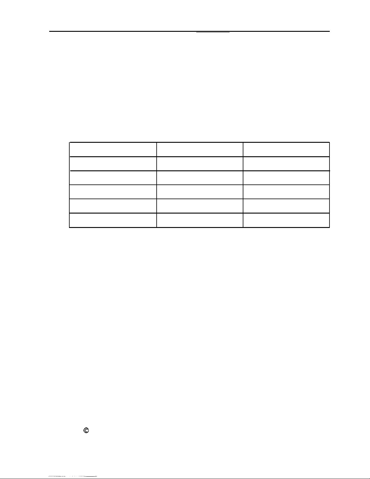
Please note that the memory configuration table shown on
pages 3-12 and
3-13
of your
User’s Guide
is incorrect. Please
replace it with the following table.
SIMM configuration
Socket U11
1MB 1MB
4MB 4MB
14MB 16MB
64MB**
* Standard soldered memory
**
Check with your dealer to see if this SIMM is available
t
With this memory configuration, the 4MB of soldered memory is disabled-
Socket U12
64MB**
Total memory
4MB*
6MB
12MB
36MB
128 MB t
Epson is a registered trademark and Progression is a trademark of Seiko Epson
Corporation.
0
Copyright
Torrance, California
1992 by Epson America, Inc.
m02184 400183400
Page 2

EPSON® PROGRESSION™
User’s Guide
l%is
@
manual is printed on recycled paper and is 100% recyclable
Page 3
FCC COMPLIANCE STATEMENT
FOR AMERICAN USERS
This equipment has been tested and found to comply with the limits for a class B digital
device, pursuant to Part 15 of the FCC Rules. These limits are designed to provide
reasonable protection against harmful interference in a residential installation. This
equipment generates, uses, and can radiate radio frequency energy and, if not installed
and used in accordance with the instructions, may cause harmful interference
to radio and
television reception. However, there is no guarantee that interference will not occur in a
particular installations If this equipment does cause interference to radio and television
reception which can be determined by turning the equipment off and on, the user is
encouraged to try to correct the interference by one or more of the following measures:
0
Reorient or relocate the receiving antenna
0
Increase the separation between the equipment and receiver
0
Connect the equipment into an outlet on a circuit different from that to which the
receiver is connected
0
Consult the dealer or an experienced radio/TV technician for help.
WARNING
The connection of a non-shielded equipment interface cable to this equipment will
invalidate the FCC Certification of this device and may cause interference levels that
exceed the limits established by the KC for this equipment. It is the responsibility of the
user to obtain and use a shielded equipment interface cable with this device. If this
equipment has more than one interface connector, do not leave cables
connected to unused
interfaces.
Changes or modifications not expressly approved by the manufacturer could void the
user’s authority to operate the equipment.
FOR CANADIAN USERS
This digital apparatus does not exceed the Class B limits for radio noise emissions from
digital apparatus as set out in the radio interference regulations of the Canadian
Department of communications.
L.e p&sent appareil num&que
n&net
pas de bnits
radio&&iques d+assant
les limites
applicables aux appareik num&riques de Chsse B prescrites dans le rhgkment sur le
brouillageradioe]ectriqw~ct~parle~~des~~~ti~duCaMda
Page 4

IMPORTANT NOTICE
DISCLAIMER OF WARRANTY
Epson America makes no representations or warranties, either express or implied, by or
with respect to anything in this manual, and shall not be liable for any implied warranties
of merchantability and fitness for a particular purpose or for any indirect, special or
consequential damages. Some states do not allow the exclusion of incidental or
consequential damages, so this exclusion may not apply to you
COPYRIGHT NOTICE
All rights
system, or transmitted, in any form or by any means, electronic, mechanical,
photocopying. recording, or otherwise,
America, Inc. No patent liability is assumed with respect to the use of information
contained herein. Nor is any liability assumed for damages resulting from the use of the
information contained herein. Further, this publication and features described herein are
subject to change without notice.
Epson is a registered trademark and Epson Progression is a trademark of Seiko Epson
Corporation.
VirtualCache is a trademark of Epson Portland, Inc.
General notice: Other product names used herein are for identification purposes only and
may be trademarks of their respective companies.
reserved No part of this publication may be reproduced, stored in a retrieval
without the prior written permission of Epson
TRADEMARKS
Copyright 0 1992 by Epson America, Inc.
Torrance, California Y74599100100
ii
Page 5

Important Safety Instructions
1.
Read all of these instructions and save them for later reference.
2.
Follow all warnings and instructions marked on the computer.
3.
Unplug the computer from the wall outlet before cleaning. Use a
damp cloth for cleaning; do not use liquid or aerosol cleaners.
4.
Do not spill liquid of any kind on the computer.
5.
Do not place the computer on an unstable cart, stand, or table.
6.
Slots and openings in the cabinet and the back or bottom are
provided for ventilation; do not block or cover these openings.
Do not place the computer near or over a radiator or heat
register.
7.
Operate the computer using the type of power source indicated
on its label. If you are not sure of the type of power available,
consult your dealer or local power company.
8.
If you plan to operate the computer in Germany, observe the
following safety precaution:
To provide adequate short-circuit protection and overcurrent
protection for this computer, the building installation must be
protected by a 16 Amp circuit breaker.
9.
Connect all equipment to properly grounded (earthed) power
outlets. If you are unable to insert the plug into an outlet,
contact your electrician to replace your outlet. Avoid using
outlets on the same circuit as photocopiers or air control
systems that regularly switch on and off.
10.
Do not allow the computer’s cord to become damaged or frayed.
iii
Page 6

11.
If you use an extension cord with the computer, make sure the
total of the ampere ratings of the devices plugged into the
extension cord does not exceed the ampere rating for the
extension cord. Also, make sure the total of all products
plugged into the wall outlet does not exceed 15 amperes.
12.
Do not insert objects of any kind into this product through the
cabinet slots.
13.
Except as specifically explained in this User’s Guide, do not
attempt to service the computer yourself. Refer all servicing to
qualified service personnel.
14.
Unplug the computer from the wall outlet and refer servicing to
qualified service personal under the following conditions:
A. When the power cord or plug is damaged.
B.
If liquid has entered the computer.
C. If the computer does not operate normally when the
operating instructions are followed. Adjust only those
controls that are covered by the operating instructions.
Improper adjustment of other controls may result in
damage and often requires extensive work by a qualified
technician to restore the computer to normal operation.
D.
If the computer has been dropped or the cabinet has been
damaged.
E. If the computer exhibits a distinct change in performance.
iv
Page 7
Instructions Importantes de Sécurité
1.
Lire compMtement les instructions qui suivant et les conserver
pour references futures.
2.
Bien suivre tous les avertissements et les instructions indiquks
l’ordinateur.
Wbrancher l’ordinateur de toute sortie murale avant le nettoyage.
3.
Utiliser un chiffon humide; ne jamais utiliser un nettoyeur
liquide ou une bonbonne aerosol.
4.
Ne jamais renverser un liquide d’aucune sorte sur l’ordinateur.
5.
Ne pas placer l’ordinateur sur un chariot, un support, ou une table
instable.
6.
Les events dans le meubles, a l’arriere et en dessous sont concus
pour Yakration; on ne doit jamais les bloquer. Ne pas placer
l’ordinateur pres d’une source de chaleur dire&e.
7.
Le fonctionnement de l’ordinateur doit s’effectuer conformement
au type de source d’aiimentation indiqu&e sur l’etiquette. Dans
le cas d’un doute de la source disponible, on doit communiquer
avec le concessionaire ou la compagnie d’&ctriciM.
sur
8.
Lorsqu’on desire utiliser l’ordinateur en Allemagne, on doit
observer les normes s&uitaires qui suivent:
Afin d’assurer une protection adequate a l’ordinateur contre les
court-circuits et le survoltage, l’installation de l’&difice doit
comprendre un disjoncteur de 16 amp.
9.
On doit brancher tout l’+ipement darts une sortie reli4e a la
masse. Lorsqu’il est impossible d’inserer la fiche dans la prise,
on doit retenir les services d’un electricien ou remplacer la prise.
Ne jamais utiliser une prise sur le m&ne circuit qu’un appareil a
photocopie ou un syst&me de contrble d’aeration avec
commutation marche-arr&.
V
Page 8
10. S’assurer que le cordon d’alimentation de l’ordinateur n’est pas
effrs.
11. Dans le cas ou on utilise un cordon de rallonge avec l’ordinateur,
on doit s’assurer que la valeur totale d’amperes branches dans
le cordon n’excede en aucun temps les amperes du cordon de
rallonge. La quantit6 totale des appareils branches dam la prise
murale ne doit jamais
exckkr 15
amperes.
12.Ne
13. Sauf tel que spkifie dans la notice d’utilisation, on ne doit jamais
14. Debrancher l’ordinateur de la prise murale et confier le service au
jamais ins&w un objet de quelque sorte que ce soit dans les
cavites de cet appareil.
tenter d’effectuer une reparation de I’ordinateur. On doit r&!rer
le service de cet appareil a un technicien qualifie.
personnel de service qualifie selon les conditions qui suivent:
A. Lorsque le cordon d’alimentation ou la prise sont
endommagk
B.
Lorsqu’un liquide s’est infib& dans l’ordinateur.
C. Lorsque I’ordinateur refuse de fonctionner normalement
meme en suivant les instructions. N’ajuster que les
commandes qui sont ~num&!es clans les instructions de
fonctionnement. Tout ajustement inad6quat de tout autre
contr6le peut provoquer un dommage et souvent nkcessiter
des rkparations &labor&s par un technicien qua&S afin de
remettre l’appareil en service.
D.
Lorsqu’on a
le boitier.
&hap@
l’ordinateur ou que l’on a endommage
vi
E.
Lorsque l’ordinateur demontre un changement note au niveau
de sa performance.
Page 9

Optional Equipment
Memory..
Drives
..............................
CPU Card
OverDrive Module
Math Coprocessor
.........................
...........................
............................
.......................
.......................
Video Daughterboard
VGA UtiIities
How to Use This Manual
Where to Get Help
.............................
......................
..........................
.....................
2
2
3
3
3
3
4
4
5
6
Chapter
Turning On the Computer
Turning Off the Computer
Using Disks and Disk Drives
1
Using Your Computer
.....................
..................
....................
How Disks Store Data
Types of Diskette Drives
.....................
...................
Caring for Diskettes and Diskette Drives
Write-protecting Diskettes
Inserting and Removing Diskettes
..................
..............
Using a Single Diskette Drive System
Formatting Diskettes
Making Backup Copies
Using a Hard Disk Drive
Special Keys on the Keyboard
Stopping a
Command or Program
Resetting the Computer
Locking the Computer’s Cover
.....................
....................
...................
...................
.................
.......................
..................
.........
............
1-2
1-4
1-5
1-6
1-7
1-10
1-12
1-14
1-16
1-17
1-17
1-18
1-20
1-21
1-22
1-23
vii
Page 10

Using a Password
Changing a Password
Deleting a Password
Using Your Computer as a Network Server
Using a Password in Network Server Mode
Changing the Processor Speed
Entering Keyboard Commands
Using the ESPEED Program
Changing the Speaker Volume
Preparing the Hard Disk for Moving
Using AUTOEXEC.BAT and Other Batch Files
..........................
...................
.....................
...........
........
...................
...............
.................
..................
...............
.........
Chapter 2 Accessing Internal Components
1-24
1-25
1-26
1-27
1-28
1-29
1-31
1-32
1-34
1-36
1-37
Special Precautions
Removing the Cover
Removing the Front Panel
Removing the Subassembly
Replacing the Subassembly
Replacing the Front Panel
Replacing the Cover
Chapter 3
Main System Board Map
Jumper Settings
Setting the Jumpers
Option Cards
Installing an Option Card
.........................
........................
.....................
....................
....................
.....................
.........................
Installing and Removing Options
......................
...........................
......................
.............................
...................
Removing an Option Card
Memory Modules (SIMMs)
Installing SIMMs
Removing SIMMs
Replacing the CPU Card
Removing the CPU Card
Installing the CPU Card
.....................
........................
.......................
......................
...................
...................
..................
2-2
2-3
2-5
2-7
2-9
2-11
2-12
3-3
3-4
3-5
3-6
3-8
3-10
3-11
3-14
3-16
3-17
3-18
3-19
Viii
Page 11

Installing an OverDrive Module
Installing a Math Coprocessor
..................
...................
Installing the Intel 487SX/25 Microprocessor
Installing a Weitek 4167 Coprocessor
Replacing the Video Daughterboard
Using the VGA Feature Connector
................
............
...............
.......
3-22
3-24
3-26
3-27
3-29
3-34
Chapter 4
Choosing the Correct Drive Bay
Installation/Removal Sequence
Checking the IDE Hard Disk Drive Jumpers
Where to Go Next
Installing a Drive in the External Bay
Connecting the Cables
Removing a Drive From the External Bay
Installing a Hard Disk Drive in the Internal Bay
connecting the Cables
Removing a Hard Disk Drive From the Internal Bay
Post-installation Procedures
Chapter 5
Starting the Program
Deleting Tests.
Adding Tests
Running Tests
Resuming From an Error
System Diagnostic Tests
Error Messages
Installing and Removing Drives
..................
..................
...........
.......................
...............
.....................
............
.........
.....................
......
....................
Running System Diagnostics
........................
.........................
..........................
............................
.................
......................
............................
4-2
4-3
4-4
4-5
4-6
4-9
4-14
4-16
4-20
4-25
4-27
5-2
5-3
5-4
5-5
5-6
5-7
5-8
ix
Page 12

Chapter 6
Formatting a Hard Disk
Starting the Program
Formatting a New Disk
Reformatting a Used Disk
Selecting an Option
Selecting a Drive
Option 1, Format
Modifying the Defective Track Table
Formatting the Disk
Option 2, Destructive Surface Analysis
Option 3,
Nondestructive Surface Analysis
Exiting the Program
Chapter 7
Troubleshooting
Identifying Your System
Error Messages
The Computer Won’t Start
The Computer Does Not Respond
Restoring the Power Supply
Password Problems
Accessing Your System
Keyboard Problems
Monitor Problems
Diskette Problems
Diskette Drive Problems
Hard Disk Problems
Installing the Drive
Preparing the Drive
Accessing Data on the Drive
Software Problems
Printer Problems
Option Card Problems
Mouse Problems
Memory Module Problems
Math Coprocessor Problems
........................
...................
..................
......................
........................
..........................
............
.....................
..............
.........................
......................
...........................
.....................
................
.................
.........................
....................
.........................
..........................
..........................
......................
........................
......................
......................
.................
.........................
..........................
.......................
...........................
....................
....................
...........
6-2
6-3
6-3
6-4
6-4
6-4
6-7
6-8
6-9
6-11
6-12
7-1
7-2
7-5
7-6
7-8
7-9
7-10
7-11
7-12
7-13
7-15
7-16
7-17
7-18
7-18
7-19
7-20
7-22
7-23
7-23
7-24
x
Page 13

Appendix A Specifications
CPU and Memory
Controllers
Interfaces
...........................
............................
Mass Storage
Keyboard
............................
Power Supply
Environmental Requirements
.......................
..........................
..........................
Physical Characteristics
Power Source Requirements
System Memory Map
Extended VGA modes
Wingine Modes
.........................
.....................
.....................
Index
.................
....................
.................
A-1
A-4
A-4
A-5
A-5
A-4
A-7
A-7
A-8
A-9
A-10
A-11
Page 14

Introduction
Your new Epson® Progression™ computer is a very fast,
high-performance system offering flexibility and expandability
in a compact design. It provides the following features:
4MB of internal memory, expandable to 128MB
System and video BIOS shadow RAM
8KB of internal cache
VirtualCache™ -the Epson proprietary memory
architecture which allows the system to use all its system
memory as a virtual cache pool
Integrated VGA (video graphics array) controller with
Wingine™ video technology developed by Chips and
Technologies® for Microsoft® Windows™ users
Built-in serial and parallel ports
Built-in IBM® PS/2™ compatible keyboard and mouse ports
Six 16-bit option slots
Support for up to five mass storage drives: two internal and
three externally-accessible
Upgradable CPU (central processing unit) card with sockets
for a math coprocessor and an Intel
Upgradable video interface daughterboard
Password security
Lockable case.
®
OverDrive™ module
Introduction 1
Page 15

Your computer’s video and memory features work together to
make it extremely fast. The advanced system architecture
allows the CPU to communicate directly with the Wingine
video controller, providing direct throughput from the system
memory to the display. Combined with the speed and graphics
capabilities of the Wingine VGA controller, this technology
produces screen refresh rates that are ten tunes faster than
standard super VGA systems and up to five tunes faster than
systems that employ “local bus” technology.
Additionally, your computer can use all of its memory as a
virtual cache pool. Unlike most systems that provide only a
64KB or 128KB cache buffer-which typically fills up with the
first or second memory access command-your computer uses
all the RAM as a “virtual” cache buffer. You’ll notice the
improved performance especially when running
memory-consuming graphics programs such as Windows
applications or draw programs.
Using the built-in interfaces, you can connect your peripheral
devices directly to the computer so you don’t have to install
option cards. You can use the option slots to enhance your
system with extra functions such as a modem card, network
card, or additional interface ports.
Optional Equipment
You can easily upgrade your computer by installing additional
memory and a wide variety of options, as described below.
Memory
By adding 1MB, 4MB, 16MB, or 64MB SIMMs (single inline
memory modules) to the main system board, you can expand
the computer’s memory up to 128MB.
2 Introduction
Page 16

Your system can support up to five mass storage devices, such
as hard disk drives, diskette drives, a tape drive, or a CD-ROM
drive. As your storage needs expand, you can install these
drives to provide the necessary space for all your data.
Because the CPU card is replaceable, you can easily upgrade
your system without having to purchase a new computer. The
CPU card is available in three models: 486SX/25, 486DX/33,
and 486DX2/66. In addition to the system speed and
performance enhancements that come with a faster CPU, the
Wingine VGA controller speeds up your video performance to
match the capability of your CPU card.
OverDrive Module
You can also enhance your system-without replacing the CPU
card-by installing an Intel OverDrive module on the CPU
card. This doubles the internal clock speed of the
microprocessor so your system runs much faster.
Math Coprocessor
You may want to install a math coprocessor to enhance the
speed and performance of mathematical calculations in certain
application programs. Roth the 486DX/33 and the 486DX2/66
cards have a math coprocessor built into the CPU and also have
a socket for an optional Weitek® math coprocessor chip. On the
486SX/25 card you can install an Intel 487SX/25 microprocessor chip, which has a built-in math coprocessor.
Introduction 3
Page 17

Video Daughterboard
While the Wingine super VGA controller is soldered on the
computer’s main system board, the video interface is supplied
on a small, upgradable daughterboard which you can replace
with an enhanced daughterboard. The standard board provides
resolutions up to 1024 x 768 and the enhanced board supports
resolutions up to 1280 x 1024, as well as “true color.” The 24-bit,
true color technology allows your compatible monitor to
display in millions of colors, instead of just 16 or 256.
Check with your authorized Epson dealer for information on
optional equipment. For installation instructions, see
Chapters 2,3, and 4 of this manual.
VGA Utilities
Your computer comes with special MS-DOS VGA device
drivers and utilities for use with the integrated VGA interface.
With these utilities, you can take advantage of extended VGA
features such as high resolutions and 132-column text mode
when you run popular application programs. The Wingine
controller works with the display drivers to provide sharp,
clear resolutions of up to 1280 x 1024 for the Windows
environment. See the
instructions.
VGA Utilities Guide
for installation
4 Introduction
Page 18
This manual contains the information you need to get the best
results from your computer. You don’t have to read everything
in this book; check the following summary.
Chapter 1 covers general operating procedures, such as turning
the computer on and off, using disks and disk drives, entering a
password, and changing the processor speed.
Chapter 2 provides instructions for removing and replacing the
computer’s cover, front panel, and subassembly so you can
access components inside the computer.
Chapter 3 describes how to change jumper settings and install
optional equipment such as option cards, memory modules, a
CPU card, an OverDrive module, a math coprocessor, and a
video daughter-board.
Chapter 4 explains how to install and remove disk drives.
Chapter 5 provides instructions for running system diagnostics.
Chapter 6 gives the procedure for formatting a hard disk.
Chapter 7 contains troubleshooting tips.
Appendix A lists the specifications of your computer.
At the end of this manual, you’ll find a glossary and an index.
Note
Please see the
Setup Guide
for instructions on setting up your
system and running the SETUP program.
Page 19

Where to Get Help
If you purchased your computer in the United States, Epson
America provides local customer support and service through a
nationwide network of authorized Epson dealers and Service
Centers. Epson also provides the following support services
through the Epson Customer Support Center at (800) 922-8911:
a
Technical assistance with the installation, configuration,
and operation of Epson products
a
Assistance in locating your nearest Authorized Epson
Reseller or Service Center
a
Sales of ribbons, supplies, parts, documentation, and
accessories for your Epson product
a
Customer Relations
a
Epson technical information library fax service-also
available directly by calling the toll number (310) 782-4214
a
Product literature with technical specifications on our
current and new products
a
User group information.
If you purchased your computer outside the United States,
please contact your dealer or the marketing location nearest
you for customer support and service. International marketing
locations are listed on the inside back cover.
If you need help with any software application programs you
are using, see the manuals that came with the programs for
information about the technical support offered by the
manufacturer.
6
introduction
Page 20
Chapter 1
Using Your Computer
This chapter gives you a brief overview of some basic computer
operations that you’ll use on a daily basis, such as how to turn
your system on and off, use diskettes and disk drives, and reset
the computer.
If you are familiar with these aspects of operating a computer,
you may want to skip the first few sections of this chapter.
However, be sure to read the later sections which describe
system operations specific to your computer, such as using a
password, changing the processor speed, and preparing the
hard disk for moving.
Using Your Computer
1-1
Page 21

Turning On the Computer
Before turning on your computer, check the following safety
rules to avoid accidentally damaging your computer or injuring
yourself:
Cl
Do not connect or disconnect any power cables or
peripheral device cables (including the mouse or keyboard)
when the computer’s power is on.
P
Never turn on the computer with a protective card in a
5.25-inch diskette drive.
0
Never turn off or reset your computer while a disk drive
light is on. This can destroy data stored on the disk.
0
Always wait at least 10 seconds after you turn off the
power before you turn it on again. This prevents possible
damage to the computer’s electrical circuitry.
Follow these steps to turn on your system:
1.
Turn on the monitor, printer, and any other peripheral
devices connected to the computer.
1-2
2.
If you do not have a hard disk (or if you have not installed
the operating system on the hard disk), insert your main
operating system diskette in drive A.
Note
If you do not have a hard disk, you need to insert the
operating system diskette each time you turn on your
system so the computer can copy the operating system
to its memory. See your operating system manual for
more information.
Using Your Computer
Page 22
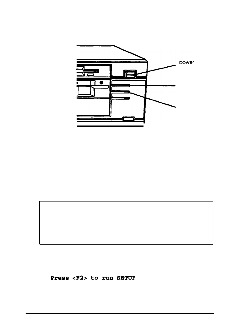
3.
To turn on the computer, press the power button located on
the right side of the front panel, as shown below.
button
power
indicator
hard disk
access light
The power indicator below the button lights up. After a few
seconds, the computer displays a count of its system memory,
and then performs its power-on diagnostics. This is a series of
checks the computer runs each time you turn it on to make sure
everything is working correctly. (If necessary, use the controls
on your monitor to adjust the screen display.)
Note
If you or your dealer has made a major change to your
system, such as adding a disk drive, you may need to wait a
few minutes for your computer to complete power-on
diagnostics the first time you turn it on.
When the system has successfully completed its diagnostics,
you see the following prompt:
Press
<F2>
to
run
SETUP
Using Your Computer
1-3
Page 23
Note
If your computer’s configuration does not match the
information stored in the computer’s CMOS RAM (defined
through the SETUP pro
a prompt to press the
am), you see an error message and
F2
?3
key. Press
[F21
to run the
SETUP program to correct the information. (See Chapter 2 of
the
Setup Guide
for instructions.)
If you do not want to run SETUP, ignore the prompt. Your
computer then loads the operating system from the hard disk
or the diskette in drive A. (If the operating system has not been
installed on the hard disk or is not on the diskette you inserted,
the computer displays an error message. See your operating
system manuals for installation instructions.)
What happens next depends on how your computer is set up.
If it is configured to automatically load a program (such as
Windows or a word processing program), you see the first menu
or screen display of that program. If not, you may see the
operating system prompt, such as
C
: \ B or
A>.
See your
application program manuals for further instructions.
Turning Off the Computer
Whenever you turn off your system, follow these steps:
1.
Save your data and exit any program you are using.
2.
Check the hard disk access light and the diskette drive light(s)
to make sure they are not on. (See the illustration on page
1-3 to locate these lights.) Do not turn off the computer if a
drive light is on, because you can damage the drive or lose
data.
1-4
Using Your Computer
Page 24
3.
Remove any diskette(s) from the diskette drive(s).
4. Press the power button to turn off the computer and then
turn off any peripheral devices (monitor, printer, etc.).
If you need to move your computer, always wait at least
20
seconds after turning it off before you move it. This
allows your hard disk drive’s read/write heads to move
away from the disk to a safe location. If you move your
computer before this happens, you could damage your
hard disk drives.
Using Disks and Disk Drives
The disk drives in your computer allow you to store data on
disk, and then retrieve and use your stored data. This section
explains how disks work and tells you how to:
Cl
Use different types of diskettes and diskette drives
Q
Care for your diskettes and diskette drives
0
Write-protect diskettes
0
Insert and remove diskettes
0
Use a single diskette drive system
0
Format diskettes
0
Make backup copies
CI
Use a hard disk drive.
Using Your Computer
1-5
Page 25
How Disks Store Data
Diskettes are made of flexible plastic coated with magnetic
material. This plastic is enclosed in a square jacket that is either
slightly flexible (5.25-inch diskette) or hard (3.5-inch diskette).
Unlike a diskette, a hard disk is rigid and fixed in place. It is
sealed in a protective case to keep it free of dust and dirt. A
hard disk stores data the same way that a diskette does, but it
works much faster and has a much larger storage capacity.
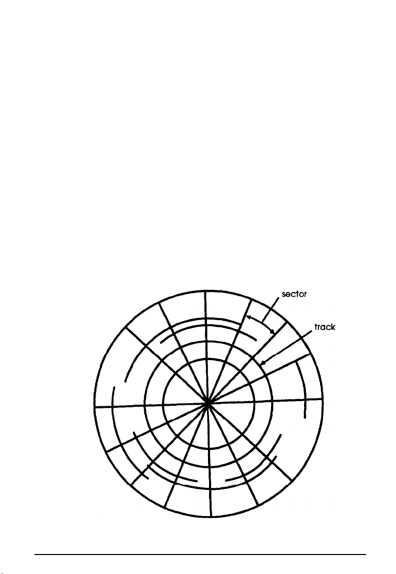
All disks are divided into data storage compartments by sides,
tracks, and sectors. Double-sided diskettes store data on both
sides. On each side are concentric rings, called tracks, on which
a disk can store data.
A disk is further divided by sectors, which can be visualized as
pie slices. The illustration below provides a simple
representation of tracks and sectors.
1-6
Using Your Computer
Page 26

Double-sided, double-density diskettes have either 40 or 80
tracks on each side, and double-sided, high-density diskettes
have 80 tracks on each side. Diskettes can have 8,9,15, or 18
sectors per track.
A hard disk consists of two or more platters stacked on top of
one another and thus has four or more sides. In addition, a hard
disk has many more tracks per side than a diskette, but the
number of tracks depends on the capacity of the hard disk. The
number of sectors depends on the type of hard disk.
Your computer uses the read/write heads in a disk drive to
store and retrieve data on a disk. To write to a disk, the
computer spins it to the position under the read/write head
where the data is to be written. A diskette has an exposed area
where the read/write head can access it.
Because data is stored magnetically, you can retrieve it, record
over it, and erase it just as you play, record, and erase music on
a cassette tape.
Types of Diskette Drives
The following list describes the four types of diskette drives
you can use in your computer and which diskettes to use with
them:
D
l.44MB drive-use 3.5-inch, double-sided, high-density,
135 TPI (tracks per inch), l.44MB diskettes. These diskettes
contain 80 tracks per side, 18 sectors per track, and hold up
to 1.44MB of information (approximately 600 pages of text).
Note
MB stands for megabyte, which equals 1024KB (or
1,048,576 bytes). KB stands for kilobyte, which equals
1024 bytes. Each byte represents a single character, such
as A, $, or 3.
Using Your Computer
1-7
Page 27

1.2MB drive-Use 5.25-inch, double-sided, high-density,
96 TPI, 1.2MB diskettes. These diskettes contain 80 tracks
per side, 15 sectors per track, and hold up to 1.2MB of
information (approximately 500 pages of text).
720KB drive-Use 3.5-inch, double-sided, double-density,
135 TPI, 720KB diskettes. These diskettes contain 80 tracks
per side, 9 sectors per track, and hold up to 720KB of
information (approximately 300 pages of text).
360KB drive-use 5.25-inch, double-sided, double-density,
48 TPI, 360KB diskettes. (You can also use single-sided,
160KB or 180KB diskettes.) These diskettes contain 40
tracks per side and 8 or 9 sectors per track. With 8 sectors
per track, a diskette holds up to 320KB. With 9 sectors per
track, a diskette holds up to 360KB of information
(approximately 150 pages of text).
Note
You
must format a new diskette before you can store data on
it. See “Formatting Diskettes,” later in this section.
Drive and diskette incompatibilities
If your computer has more than one type of diskette drive, or if
you use different types of diskettes, you need to be aware of
certain incompatibilities between the drives and diskettes.
Because of the type and size differences, you cannot use a
3.5-inch diskette in a 5.25-inch drive or vice versa. There are
also limitations on using diskettes that are the same size as the
drive but have different capacities. The following tables
summarize the possibilities and limitations.
1-8
Using Your Computer
Page 28
5.25-inch drive/diskette compatibility
Drive type Diskette types it can read from and write to
360KB
1.2MB 1.2MB, 36OKB,* 32OKB,* 18OKB,* 160KB*
l
* If you write to this diskette in a 1.2MB drive, you may not be able to read it
or write to it In a 360KB drive later.
3.5-inch drive/diskette compatibility
Drive type
720KB
1.44MB
360KB, 320KB, 180KB, 160KB
Diskette types it can read from and write to
720KB
1.44MB, 720KB
Because of possible incompatibilities, always indicate the
diskette type and density when you label your diskettes.
(Usually this information appears on the manufacturer’s label.)
Note
If you want to format a 720KB diskette in a 1.44MB drive or
format a 360KB diskette in a 1.2MB drive, make sure you
include the correct parameter in your format command.
See your operating system manuals for instructions.
If you have any combination of the above drives (1.44MB,
1.2MB, 720KB, or 360KB) and you are using MS-DOS, you can
copy files from one drive to another-using COPY or
XCOPY -as long as the correct diskette type is in each drive.
You can also use these commands to copy files between a hard
disk and any type of diskette. However, you cannot use the
MS-DOS DISKCOPY command to copy from one diskette drive
to another if the two drives are not the same type. For more
about copying files and diskettes, see your MS-DOS or other
operating system manuals.
Using Your Computer
1-9
Page 29

Caring for Diskettes and Diskette Drives
Follow these basic precautions to protect your diskettes and
avoid losing data:
P
Remove all diskettes before you turn off the computer.
If you have a diskette that contains data you
don’t want to accidentally write over or erase,
be sure you write-protect it. This is especially
important for your operating system and
application program diskettes. See ‘Writeprotecting Diskettes,” below, for more details.
P
Do not remove a diskette from the diskette drive or reset or
turn off the computer while the drive light is on. This light
indicates that the computer is copying data to or from a
diskette. If you interrupt this process, you can destroy data.
Keep diskettes in a moderate environment.
Don’t leave them sitting in the sun or in
extreme cold or heat because this can destroy
the data.
1-10
P
Keep diskettes away from dust and dirt. Small particles of
dust or dirt can scratch the magnetic surface, destroy data,
and ruin the read/write heads in a diskette drive.
Keep diskettes away from magnetic fields,
such as those generated by electrical
appliances, telephones, and loudspeakers.
(Diskettes store information magnetically.)
Using Your Computer
Page 30
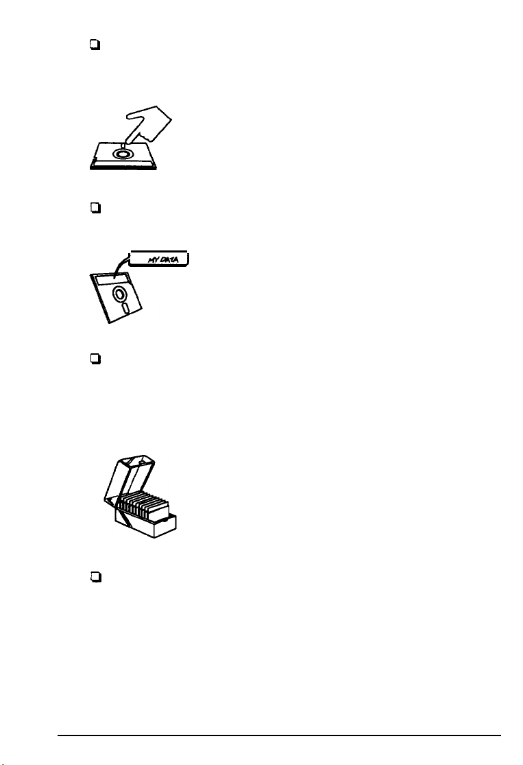
Q
Do not place diskettes on top of your monitor or near an
external hard disk drive.
Always hold a 5.25-inch diskette by its
protective jacket and never touch the magnetic
surface (exposed by the read/write slot). The
oils on your fingertips can damage it.
Q
Never wipe, brush, or try to clean diskettes in any way.
Write on a diskette label before you attach it to
the diskette. If you need to write on a label that
is already on the diskette, use only a soft-tip
pen-not a ballpoint pen or a pencil.
0
Carefully label your diskettes and indicate the type and
density. Do not stick several labels on top of one another;
this can make it difficult to insert and remove the diskette
in the drive.
Store diskettes in their protective envelopes and
in a proper location, such as a diskette container.
Do not store diskettes flat or stack them on top
of each other.
0
Do not place anything on top of your diskettes, and be sure
they do not get bent.
Using Your Computer
1-11
Page 31

Write-protecting Diskettes
You can write-protect a diskette to prevent its data from being
altered. When a diskette is write-protected, you can read it and
copy data from it, but you cannot store new data on it or delete
any files it contains.
To write-protect a 5.25-inch diskette, cover the small,
rectangular notch (shown below) with an adhesive
write-protect tab. Write-protect tabs usually are included in a
new package of blank 5.25-inch diskettes.
To remove the write protection, peel off the write-protect tab.
1-12
Using Your Computer
Page 32

On a 3.5-inch diskette, the write-protect device is a small switch
on the back of the diskette in the lower right comer, shown
below. To write-protect a 3.5-inch diskette, slide the switch
toward the edge of the diskette until it clicks into position,
exposing a hole in the comer.
switch
To remove the write protection, slide the switch toward the
center of the diskette until it clicks into position and the hole is
covered.
or switch so they are
Using Your Computer
1-13
Page 33

Inserting and Removing Diskettes
If you have a 5.25-inch diskette drive, insert a diskette as
follows: hold the diskette with the label facing up and the
read/write slot leading into the drive, as shown below.
latch
Slide the diskette all the way into the slot. Then turn the latch
down to lock it in a vertical position. This keeps the diskette in
place and enables the read/write heads in the drive to access
the diskette.
When you want to remove a diskette, first make sure the disk
drive light is off. Then flip up the latch and carefully pull out
the diskette. Place it in its protective envelope and store it in a
proper location, such as a diskette container.
1-14
Using Your Computer
Page 34

If you have a 3.5-inch diskette drive, insert the diskette with the
label facing up and the metal shutter leading into the drive, as
shown below. Slide the diskette into the drive until it clicks into
place.
release button
metal shutter
When you want to remove the diskette, make sure the drive
light is off; then press the release button. When the diskette
pops out, remove it and store it properly.
Never remove a diskette, or reset or turn off the computer
on. You could lose data. Also,
remove all diskettes before you turn off the computer.
Using Your Computer
1-15
Page 35

Using a Single Diskette Drive System
Most operating systems expect the computer to have at least
two diskette drives and display prompts and messages
accordingly. MS-DOS, for example, recognizes the first diskette
drive (the top drive) as drive A and a second diskette drive as
drive B. If you have only one diskette drive, MS-DOS can treat
it as both A and B when you need to perform operations that
normally would use two diskette drives.
For example, if you enter a command to copy data from A to B,
MS-DOS copies the data from the first diskette you place in the
drive (which would be drive A) to the computer’s memory.
Then MS-DOS prompts you to insert another diskette (for
drive B) and copies the data from memory to the new diskette.
When copying is complete, you see a prompt to insert the
original diskette (A).
Because you may often swap diskettes this way, it is important
to remember which diskette is which. It is also a good idea to
write-protect your original diskette. (See ‘Write-protecting
Diskettes,” above.)
If you have a hard disk and one diskette drive, you can load the
operating system and application programs from the hard disk,
create and store your data there, and use the diskette drive just
for copying data to or from diskettes.
However, if you have only one diskette drive and no hard disk,
you need to use that drive to load the operating system as well
as any application program you are using. First, insert the
operating system diskette (the MS-DOS Startup diskette, for
example) in drive A and load the operating system; this copies
it to the computer’s memory (RAM) so you do not need to
leave the system diskette in the drive. Then remove the system
diskette and insert your application program diskette to load
that data into memory, too. See your application program
manual for detailed instructions.
1-16
Using Your Computer
Page 36

Formatting Diskettes
Before you can store data on a new diskette, you must format it.
Formatting prepares the diskette so that the operating system
can write data on it. You need to do this only once, before you
use the diskette for the first time.
You can also reformat previously used diskettes to store new
data. This process erases all the data on the diskette, so be sure
you do not want to save any of the files on a used diskette
before you format it. See your operating system manuals for
instructions on formatting diskettes.
Making Backup Copies
It is important to make copies of all your data and system
diskettes. Make backup (or working) copies of all diskettes that
contain programs, such as your operating system, Reference,
and Utility diskettes; then use only the copies. Store the original
diskettes away from your working diskettes. Also, copy your
data diskettes regularly, whenever you revise them, and store
them away from your originals.
If you have a hard disk, you’ll probably use it to store the
programs and data files you use regularly. Keep backup copies
of all your files on diskettes or tapes (if you have a tape backup
drive).
Using Your Computer
1-17
Page 37

Using a Hard Disk Drive
Using a hard disk is similar to using a diskette. However, the
hard disk provides several advantages:
P
A 240MB hard disk can store as much data as
approximately 198 1.2MB diskettes or 165 1.44MB diskettes.
P
Your computer can perform all disk-related operations
faster.
0
You can store frequently used programs and data files on
the hard disk, eliminating the inconvenience of swapping
diskettes to access different files.
The added storage capacity makes it easy to move back and
forth between different programs and data files. However,
because it is so easy to add programs and files to your hard
disk, you may find yourself trying to organize hundreds of files.
Most operating systems let you keep related files together in
directories and subdirectories so they are easy to find and use.
See your operating system manuals for instructions on
managing your files and directories.
1-18
Note
A hard disk must be partitioned and formatted before you
can use it. Be sure you have performed the procedures
described in your operating system manuals to prepare your
hard disk for use.
Using Your Computer
Page 38

Backing up the hard disk
While the hard disk is very reliable, it is essential to back up
your hard disk files to diskettes or tapes in case you lose some
data accidentally. Make copies of all your system and
application program diskettes before copying the programs to
the hard disk. After you create data files on the hard disk, be
sure to back them up whenever you revise them to keep your
backup diskettes or tapes up-to-date.
caring for your hard disk
Follow these precautions to protect your hard disk drive from
damage and to avoid losing data:
Q
Never turn off or reset the computer when the hard disk
access light is on. This light indicates that the computer is
copying data to or from the hard disk. If you interrupt this
process, you can lose data. (See the illustration on page 1-3
to locate the hard disk access light.)
Ct
Never attempt to open the hard disk drive. The disk itself is
enclosed in a sealed container to protect it from dust.
Cl
If you need to move your computer, you may need to run
the HDSIT program to prepare the hard disk for moving, as
described on page 1-36.
Using Your Computer
1-19
Page 39

Special Keys on the Keyboard
Certain keys on your keyboard serve special functions when
your computer is running your operating system or application
programs, as described in the table below.
Special key functions
Moves the cursor one tab to the right In normal
mode and one tab to the left in Shift mode.
Changes the letter keys from lower- to uppercase;
changes back to lowercase when pressed again.
The numeric/symbol keys on the top row of the
keyboard and the symbol keys in the main part of
the keyboard are not affected.
Ishml
Produces uppercase characters or the top
symbols on the keys when used with the main
character keys. Produces lowercase characters
when the Caps Lock function is on.
Works with other keys to perform special (control)
functions.
Works with other keys to enter alternate character
codes or functions.
Moves the cursor back one space, deleting the
character to the left of the cursor.
Ends a line of keyboard input or executes a
command.
Turns the insert function on and off.
Deletes the character marked by the cursor.
I
I
I
Nl
Cancels the current command line or operation.
1-20
Using Your Computer
Page 40

Special key functions (continued)
hrpo=
Changes the function of the numeric/cursor keys
from entering numbers to positioning the cursor.
=-l-[F1zl
pa
lserdllpal
Ipwrrl
m
The
[$GLiC), [lunlodr],
Perform special functions within application
programs.
Prints the screen display on a printer.
Generates the System Request function in some
application programs (used with
Controls scrolling in some applications.
Suspends the current operation.
Stops the current operation (used with
and
[*a]
keys work as toggles; press
I)],.
[CM]).
the key once to turn on a function and again to turn it off. When
the function is enabled, the corresponding light in the upper
right comer of the keyboard is lit.
Stopping a Command or Program
You may sometimes need to stop a command or program while
it is running. If you have entered an MS-DOS or application
program command that you want to stop, try one of the
following:
I
Q
Hold down
P
Hold down
i
[ctrll
and press
and
press
[cl
m.
If these methods do not work, you may need to reset the
computer as described below. Do not turn off the computer to
exit a program or stop a command unless you have to, because
the computer erases any data you did not save.
Using Your Computer
1-21
Page 41

Resetting the Computer
Occasionally, you may want to clear the computer’s current
settings or its memory without turning it off. You can do this
by resetting the computer.
For example, if an error occurs and the computer does not
respond to your keyboard entries, you can reset it to reload
your operating system and try again. However, resetting erases
any data in memory that you have not saved; so reset only if
necessary.
Caution
Do not reset the computer as a means to exit a program.
Some programs classify and store new data when you exit
them in the normal
without properly exiting a program, you may lose data.
To reset the computer, the operating system must be either on
the hard disk or on a diskette in drive A; so if you do not have a
hard disk, insert a system diskette in drive A.
There are two ways to reset the computer:
manner.
If you reset the computer
1-22
0
If you are using MS-DOS, hold down m and
press
[.
The screen goes blank for a moment and then
the computer should reload your operating system.
Q
Press the RESET button on the front panel (shown in the
(Alto
following illustration); this method works even when the
computer does not respond to your keyboard entries.
Using Your Computer
and
Page 42

RESET button
If resetting the computer does not correct the problem, you
probably need to turn it off and on again to reboot it. Remove
any diskette(s) from the diskette drive(s). Turn off the
computer and wait 10 seconds. If you do not have a hard disk,
insert a system diskette in drive A. Then turn on the computer.
locking the Computer’s Cover
You can lock the cover onto the computer to prevent
unauthorized users from accessing its internal components.
To lock the cover, insert the key as shown on the left and turn it
clockwise. To unlock the cover, insert the key as shown on the
right and turn it counterclockwise.
Using
Your
Computer
1-23
Page 43

Using a Password
If you set a password when you ran the SETUP program, you
must enter it every time you turn on or reset the computer.
Follow these steps to use your password:
1.
If you do not have a hard disk, insert your system diskette
in drive A.
2.
Turn on or reset the computer. You see a number and the
key prompt:
3.
Type your password. The key turns when you type a
character, but the screen does not display the characters
you type. Then press
You have three chances to enter the correct password. The
number that appears before the key prompt indicates how
many tries you have left. After the third incorrect try, the screen
displays a zero, the keyboard locks up, and you cannot use the
computer. Press the RESET button and try to enter the correct
password again.
m
Note
If you do not know the correct password, see “Password
Problems” in Chapter 7.
After you type the password correctly and press I, a
happy face character appears. Then the computer loads the
operating system and displays the command prompt.
1-24
Using Your Computer
Page 44

Note
If you turned on network server mode when you ran the
SETUP program, you need to use a different procedure to
enter your password. See “Using Your Computer as a
Network Server” on page 1-27.
Changing
To change your password, follow these steps:
1.
2.
a
Password
If you do not have a hard disk, insert your system diskette
in drive A.
Turn on or reset the computer. At the key prompt, enter
your current password followed by a forward slash (/) and
the new one you want to use. For example, if your current
password is 123 and you want to change it to ABC, type:
123/ABC
The screen does not display what you type.
Do not use characters requiring the m key, such as %, @,
or #, in your new password. The computer does not
distinguish between characters that are produced with the
m
key and those that are not.
3.
Press
m
A happy face character appears and then the
computer loads the operating system.
Using Your Computer
1-25
Page 45

Note
You can also change your password using the SETUP
program. See Chapter 2 of the Setup Guide for instructions.
Deleting a Password
To delete your password, follow these steps:
1.
If you do not have a hard disk, insert your system diskette
in drive A.
2.
Turn on or reset the computer. At the key prompt, enter
your current password followed by a forward slash. For
example, if your password is 123, type:
123/
3.
Press
m.
A happy face character appears and then the
computer loads the operating system.
The next time you turn on or reset the computer, it does not
request a password and loads the operating system
immediately.
Note
You can also delete your password using the SETUP
program. See Chapter 2 of the
Setup Guide
for instructions. If
you do not know the password, see “Password Problems” in
Chapter 7.
1-26
Using Your Computer
Page 46

Using Your Computer as a Network Server
A network server is the master computer in a network and
provides storage space for the other computers connected to it.
It can also write files to and read files from the other
computers, making it the most powerful computer in the
network.
Even if no one is typing
keyboard, the server can process commands sent to it from
other computers. If you use your computer as the network
server, you may want to prevent unauthorized users from
entering commands at the keyboard. To provide this security,
you can enable a password in network server mode using the
SETUP program.
If you set a password but did not turn on network server mode,
you enter the password before the computer loads the operating
system or the network software. Once you load it, anyone can
access your system by typing commands on the keyboard.
However, if you set a password and turn on network server
mode, you can load your operating system or network software
before you enter the password. This allows other computers in
the network to access the system, but prevents unauthorized
users from entering commands at your keyboard and using any
network server access privileges.
When you boot the computer in network server mode, you do
not see the key prompt
mode was turned off. The password prompt is hidden to
prevent unauthorized users from knowing that a password is
required.
commands
(h),
as you would if network server
at the network server
Using Your Computer
1-27
Page 47

You do not have to set a password in network server mode to
use your computer as a network server, but it is helpful. See
“Setting the Password Options” in Chapter 2 of the
Setup Guide
enabling network server mode. Then read the next section to
use your network password.
for instructions on setting the password and
Using a Password in Network Server Mode
When you turn on or reset the computer, it loads your
operating system or network software from your hard disk
and you see either the command prompt or the first screen
displayed by your network software.
Note
If you boot your computer from a diskette in drive A,
however, you see the password key prompt before the
computer loads your operating system or network software.
Follow the instructions in “Using a Password” on page 1-24
to enter your password in this situation.
Follow these steps to enter your password:
1.
Turn on or reset your computer. You do not see the key
prompt
you to enter the correct password.
2.
Type your password and press
display what you type.
Now you should be able to use your computer. Press a key
such as
If you entered an incorrect password, the computer does not
respond. Type the correct password, press
the computer again.
1-28
Using Your Computer
(h)
even though the computer is now waiting for
[burl.
The screen does not
m
to see if the keyboard accepts your command.
En*r
, and try using
c!3
Page 48

Changing the Processor Speed
Your computer’s processor can operate at two speeds: high
or low. High speed is the highest speed at which your
microprocessor is capable of running, such as 33 MHz. Low
speed simulates an 8 MHz processor to provide compatibility
with older application programs.
You can also set the computer to automatic speed which
switches your computer’s processor from high to low speed
when it accesses a diskette drive.
Note
When your computer is operating at high speed, the TURBO
light on the front panel is lit. It is off when the computer is
operating at low speed.
You should use high speed for almost everything you do
because your programs will work faster. However, certain
application programs have specific timing requirements and
can run only at the slower speed. See your software manual to
determine if this is the case.
Using Your Computer
1-29
Page 49

Some copy-protected programs require the computer to run at
low speed while accessing the program on a diskette. These
programs also usually require you to leave a
key
disk-the
diskette that contains the copy protection-in the diskette
drive. If you use a copy-protected program often, you may
want to set your processor speed to change automatically to
low speed when accessing the diskette and return to high speed
when it is finished.
Depending on the type of copy-protected program you have,
you may or may not want to set the processor to automatic
speed. Follow these guidelines:
0
If you are using a copy-protected program that can run
only on a diskette or that requires a key disk, try to load the
program at high speed. If this works, you do not need to set
the speed to change automatically. If you can’t load the
program on high, set the speed to change automatically.
0
If you are using a copy-protected program that does not
require a key disk but requires a special procedure to install
it on a hard disk, set the speed to low while you are
installing the program. Then set the speed to high while
you load and run the program.
If this does not work, try installing and loading the
program at low speed and then change to high speed to run
it. Do not set the speed to change automatically.
There are three ways to change the processor speed:
0
Run the SETUP program
P
Enter a keyboard command
Cl
Run the ESPEED program.
1-30
Using Your Computer
Page 50

If you frequently use programs that require low or automatic
speed, use SETUP to change the processor speed. Your new
setting remains in effect until you change it again using SETUP.
See Chapter 2 of the
Setup Guide
for instructions.
If you use these programs only occasionally, you should use
the keyboard commands or the ESPEED program (described
below) to change the processor speed. These methods
temporarily override the SETUP processor speed setting.
Entering Keyboard Commands
You can change the processor speed temporarily by entering a
command from your keyboard. You can use these commands
only if you have enabled the Software speed change option in
the SETUP program.
option is disabled, you cannot use the keyboard commands.
The keyboard speed setting commands are listed in the table
below.
Speed setting commands
(Enabled
is the default setting.) If this
Numeric
GiElIAnl[-1
To enter these commands, hold down the
m
keypad commands
Automatic (high speed: low speed
only during diskette access)
Low (simulated 8 MHz)
[cbll
key simultaneously and then press the
&l,i5-
key on the numeric keypad.
Using Your Computer
key and the
, or
m
1-31
Page 51

Note
You can use the commands listed above while you are
running a program. However, if the program uses one of
these commands for another function, you cannot use it to
change the processor speed. For example, if you are running
a program that uses the
the cursor, you cannot enter
[cbll[m
command to move
[mJIm1[-1
-
6
to change the
processor speed to low. Another alternative is to use the
ESPEED program, described below.
The speed setting remains in effect until you do the following:
LI
Press
[cbl) (Alt) 66)
Q
Turn off the computer
Cl
Change it using the SETUP program
P
Change it with another keyboard command
P
Change it using ESPEED.
or the RESET button
Using the ESPEED Program
ESPEED provides an easy way to change the processor speed if
your application program does not recognize the
commands or
if you want
to include the program command in
[cbll
key
a batch file.
The ESPEED program is on the Reference diskette. If you
have a hard disk drive, copy the file ESPEED,EXE from your
Reference diskette
onto
your hard disk and run the program
from there. If you do not have a hard disk, insert your
Reference diskette in drive A and log onto drive A before you
enter the command to start the program.
1-32
Using Your Computer
Page 52

To run SPEED,
e the
following at the MS-DOS command
prompt and
ESPEED
You see the following messages:
Usage: ESPEED[/H] [/L]
/High
/LOW
/Auto
Set
High speed (no Auto)
Set
Low speed (no Auto)
set Auto speed
[/A]
These messages tell you the switches you should use to set the
speed to high, low, or automatic. At the MS-DOS prompt, type
the ESPEED command
again and include the appropriate
switch, such as the following:
ESPEED
(This command sets
/A
the
processor speed to change to low speed
automatically when the computer accesses a diskette.)
If you include the switch when you type the initial ESPEED
command, the program changes the speed without displaying
the command options.
The processor speed you set remains in effect until you change
it again or until
[*
[ut) [A]
you turn off the computer or reset it with
or the
RESET
button.
Using Your Computer
1-33
Page 53

Entering
the ESPEED
You may want to run the ESPEED program by including the
command in a batch file. For example, let’s say you have a
program called SLOWDOWN which requires a slower
processor speed. You could include the following commands in
a batch file to start the SLOWDOWN program:
command in a
butch file
ESPEED
SLOwDO?IN
You could name the batch file SLOW.BAT. Whenever you need
to run the SLOWDOWN program, type
The computer changes the processor speed to automatic and
starts the program.
/A
SLOW
and press
[En(wl.
Changing the Speaker Volume
Your computer contains a built-in speaker that beeps when you
perform certain operations. You can control the operation and
volume of this speaker using the SETUP program and the
SETVOL utility, described below.
To enable or disable your speaker, run the SETUP program and
change the setting of the
Chapter 2 of the
Speaker option is Enabled.)
If your speaker is enabled, you can run the SETVOL utility
to adjust the volume of the speaker as desired. The file
SETVOL.EXE is on the Reference diskette. You may want to
copy it to your hard disk for convenience.
Setup Guide.
Speaker
option, as described in
(The default setting of the
1-34
Using Your Computer
Page 54

Follow these steps to run SETVOL:
1.
If you copied SETVOL.EXE to your hard disk, log onto the
directory where it is stored.
If you did not copy the file, insert the Reference diskette in
drive A and log onto that drive.
2.
At the command prompt, type the following and press
SEWOL
[En*rl:
3. You see the volume selection menu. The VOLUME box at
the top of the screen shows the percentage of volume
currently set for your speaker, such as 50%. The solid bar in
the middle of the screen graphically displays the volume
setting as you increase or decrease it.
To decrease the volume, press
increase the volume, press
[tl, l-T-1,
[-t,[7],
or
or
[-1.
r;7.
(You can
To
use the keys on the main keyboard or the numeric keypad.)
As you change the volume, the speaker beeps so you can test
the volume of the current setting.
4.
After you have selected the volume you want, press
[Enl#l
to store the current setting and exit SETVOL. You see a
message confirming the volume setting you selected.
If you want to exit the program without saving the new
setting, press [ You see the operating system
command prompt.
The speaker volume you set remains in effect until you change
it again.
Using Your Computer
1-35
Page 55

Another way to run SETVOL is to enter the command with a
parameter at the command line. The following table lists the
parameters available.
SETVOL parameters
Parameter
/?
lnnn
/v
Just type
SETVOL
Function
Displays help information describing the SETVOL
command and options
Specifies a numeric percentage (from 0% to 100%) for
the volume
Displays the numeric percentage of the current volume
setting
followed by the parameter. For example, to
set the speaker to 50% of the maximum volume, type the
following and press
SEWOL /50
m
Be sure to include the slash (/) in the parameter.
Preparing the Hard Disk for Moving
If you need to move your computer to a new location, you may
want to run the HDSIT program provided on your Reference
diskette to protect the hard disk during the move.
HDSIT moves (or parks) the disk drive’s read/write heads to a
region on the disk surface that does not contain data, and locks
them securely in position. This protects the hard disk from
being damaged if the computer is bumped accidentally.
Many hard disk drives, including all Epson drives,
automatically park their heads when you turn off the computer.
If your hard disk drive does not do this, or if you are not sure
that it does, be sure to run HDSIT.
1-36
Using Your
Computer
Page 56

If you have not already done so, copy the HDSIT.COM and
HDSIT.VER files from the Reference diskette to your hard disk.
Then, when you want to run HDSIT, log onto the directory
where these
files are stored.
Type
HDSIT
and press (br*rl.
You see a message on the screen that tells you the disk drive’s
read/write heads will remain
locked until you reset the
computer or turn the power off and on again. The computer
then locks the heads and disables the keyboard. Remove any
diskettes and turn off the computer. Now you can move it to
the new location.
Caution
Whether you use HDSIT or not, always turn off your
computer and wait at least 20 seconds before you move it.
This allows your hard disk drive’s read/write heads to move
away from the disk to a safe location. If you move your
computer before this happens, you could damage your hard
disk drives.
Using AUTOEXEC.BAT and Other Batch Files
If you are using MS-DOS to access your application programs,
you may find that there are commands you need to run
frequently. You can automate the execution of these commands
by listing them in a special file called a batch file. When you
type the name of the batch file and press m, MS-DOS
executes the commands in the file just as if you had typed each
command from the keyboard.
If you have a word processing program that can save a file as a
text only file (sometimes called an ASCII file), you can use it to
create a batch file. You can also use the MS-DOS COPY, EDIT,
or EDLIN command, or a text editor, to create the file.
Using Your Computer
1-37
Page 57

One batch file that you may find particularly useful is called
AUTOEXEC.BAT. Every time you turn on your computer,
MS-DOS looks for the AUTOEXEC.BAT file and automatically
executes each of the commands in the file.
When you install MS-DOS, it creates an AUTOEXEC.BAT file
for you, which you can modify or replace as described above.
Be sure to name the file AUTOEXEC.BAT and store it in the
root directory of the hard disk or diskette from which you load
MS-DOS (You may want to rename your original file to
AUTOEXEC.OLD, in case you need to use it again later.)
See your MS-DOS manuals for more information about creating
and using batch files.
1-38
Using Your Computer
Page 58

Chapter 2
Accessing Internal Components
To access your computer’s internal components, you need to
remove the cover. In some cases, you may also need to remove
the front panel and the subassembly (the metal case that holds
the drive bays). The instructions in this chapter explain how to
do the following:
0
Remove and replace the cover
P
Remove and replace the front panel
Q
Remove and replace the subassembly.
Read the safety precautions on the next page before you begin.
Accessing Internal Components
2-1
Page 59

Special Precautions
As you perform the procedures described in this chapter and in
Chapters 3 and 4, observe the following precautions to avoid
damaging your equipment or injuring yourself:
Do not attempt a procedure if you have any reservations
about performing it; ask your dealer for assistance.
Always turn off
the
computer, disconnect all cables, and
wait at least 30 seconds before you remove the cover. First
disconnect the power cord from the electrical outlet and
from the computer’s back panel. Then disconnect all
peripheral devices from the computer.
Every time you remove the cover, ground yourself by
touching
the
metal inside of the computer’s back panel
before you touch any components inside. If you are not
properly grounded, you could conduct static electricity and
damage your equipment.
When disconnecting a cable from
any
internal device (such
as a disk drive), avoid pulling on the cable; grasp the plastic
connector to remove it from the socket.
When plugging a connector or a component into a socket,
be sure to position it correctly. Carefully align any
connector pins with
the corresponding
holes in the socket
before you push in the connector. Otherwise, you can
severely damage
the
equipment.
If you install an option, keep its original packaging in case
you need to remove or transport it later.
2-2
Always replace
the
computer’s cover before you turn on the
power, or the computer may
Accessing Internal Components
overheat.
Page 60

Removing the Cover
Remove the computer’s cover to do any of the following:
Change jumper settings
0
Install or remove option cards
0
Install or remove single inline memory modules (SIMMs)
0
Install or remove a CPU card
0
Install or remove a math coprocessor
0
Install or remove an OverDrive module
0
Install or remove the video daughterboard
D
Install or remove disk drives or other storage devices.
Ll
Follow these steps to remove the cover:
1.
Turn off the computer and any peripheral devices connected
to it. Then disconnect the computer’s power cord from the
electrical outlet and from the back panel. Also disconnect
any peripheral device cables that are connected to the
computer, including the keyboard cable.
2.
Turn the computer around so you are facing the back panel.
3.
If necessary, unlock the computer’s cover. (See Chapter 1 for
instructions.)
Accessing Internal Components
2-3
Page 61

4.
Loosen the three thumbscrews on the computer’s back panel
by turning them counterclockwise, as shown below. (The
screws disengage but don’t come all the way off.)
5. Grasp the sides of the cover (toward the front of the
computer) and pull it firmly toward you, as shown below.
Then lift it up and off the computer.
2-4
Accessing Internal Components
Page 62

Removing the Front Panel
You must remove the computer’s front panel if you need to
install or remove a disk drive in an external drive bay or if you
need to remove the subassembly from the computer. (If you are
installing an internal option, you do not need to remove the
front panel.)
Follow these steps:
1.
Turn the computer so you are facing the front panel.
2. Release the six tabs securing the front panel to the computer
case, as shown below. You may want to use a flat-blade
screwdriver to release the tabs.
Accessing internal Components
2-5
Page 63

Once the tabs are free, grasp the sides of the front panel
3.
and pull it
straight
toward you to disengage the two tabs at
the bottom, as shown below. Be careful not to pull the panel
off at an angle; this may bend or pop off the power and
RESET
buttons. If a button pops off, carefully place it back
on to its post.
2-6
Accessing Internal Components
Page 64

Removing the Subassembly
You need to remove the subassembly only if you are installing
or removing a hard disk drive that is mounted next to the
power supply. (See the installation instructions in Chapter 4 if
you are not sure if you need to remove the subassembly.)
Follow these steps:
1.
Turn the computer so you are facing the front panel.
2.
Disconnect the power supply and drive cables from the
backs of all the drives installed in your computer, as shown
below. Note which cables are connected to which drives so
you can easily reconnect them later.
power supply
drive cable
Accessing Internal Components
2-7
Page 65

Open the clasps holding the power supply and drive cables to
3.
the side of the subassembly, as shown below. Then remove
all the cables from the clasps. (Do not disconnect any cables
from the main system board.)
Grasp the back of the subassembly by the edge on its upper
4.
left side, as shown below, and lift up the back end.
2-8
Accessing Internal Components
Page 66

5. Pull the subassembly forward slightly to release it from the
two pins beneath the front panel opening. Then lift it out of
the computer and place it on your work surface.
Replacing the Subassembly
Follow these steps to replace the subassembly:
1.
Turn the computer so you are facing the front panel.
2. Hold the subassembly at a slight angle and guide the front of
it down through the opening in the front of the computer,
as shown below.
3. Fit the two holes in the lower front of the subassembly over
the two posts on the front of the computer case, as shown
above.
Accessing Internal Components
2-9
Page 67

Lower the back end of the subassembly into the computer.
4.
If necessary, fit the post beneath the back right edge of the
subassembly into the hole on the top of the power supply.
Then lower the subassembly all the way down.
Gather the power supply and drive cables in the clasps on
5.
the side of the subassembly; then shut the clasps.
2-10
Accessing Internal Components
Page 68

6.
Now you need to connect the drive and power supply cables
to the backs of all your drives. See “Connecting the Cables”
on page 4-9 for instructions. (If you also need to connect the
diskette and/or hard disk drive cables to the main system
board, follow steps 4 through 6 on pages 4-21 through 4-23.)
Replacing the Front Panel
Follow these steps to replace the computer’s front panel:
1.
Turn the computer so you are facing the front.
2.
Align the openings in the front panel with the power and
RESET
front of the computer case. Also align the front panel tabs
with the corresponding notches in the case. Then guide the
front panel straight onto the case, as shown below.
buttons, and any drives that extend out from the
3. Press the front panel onto the computer to fully insert all the
tabs into the notches. If all the front panel tabs do not click
into position, remove the front panel and try again.
Accessing Internal Components
2-11
Page 69

Rep/acing the Cover
Follow these steps to replace the computer’s cover:
Turn the computer so you are facing the back panel.
1.
Hold the cover at a slight angle, as shown below, and lower
2.
the front part onto the computer. Then lower the back of
the cover.
2-12
Slide the cover forward until the front edge overlaps the top
3.
edge of the front panel.
Tighten the three thumbscrews on the back panel to secure
4.
the cover to the computer.
Lock the cover onto the computer, if desired. (See Chapter 1
5.
for instructions.)
Reconnect your monitor, printer, keyboard, and any other
6.
peripheral devices you have. Then reconnect the power
cord to the back of the computer and to an electrical outlet.
Accessing Internal Components
Page 70

Chapter 3
Installing and Removing Options
You can enhance the performance of your computer by adding
a variety of options or upgrading your system components,
including the following:
D
Option cards
LJ
Memory modules
cl
Upgraded CPU card
P
Intel OverDrive module
cl
Math coprocessor
cl
Enhanced video daughterboard.
Installing and Removing Options
3-1
Page 71

This chapter provides instructions for installing the options
listed above, and for changing the jumper settings inside the
computer. Be sure to check the jumper information if you
install or remove any options in your computer.
On the next page, you’ll find an illustration of your main
system board which shows the location of any components you
may need to locate.
All the instructions in this chapter assume you have removed
the computer’s cover; if not, see Chapter 2 for the procedure.
When you finish everything you need to do inside the
computer, return to Chapter 2 for instructions on replacing the
cover.
3-2
installing and Removing Options
Page 72

Main System Board Map
As you follow the instructions in this chapter and in Chapter 4,
use the illustration below to locate the necessary components
on your main system board.
CPU cardconnector
option
slots
/
SIMM
sockets
larallel
\
I
hard disk
drive connector
.\
VGA
monitor
port
port
I
blskette dr,ve
connector
keyboard port
serial
Pop
I
VGA feature
connector
I
I
-
mouse port
I
VI&O
daughterboard
connectors
I
power
SUPPlY
connectors
JP3
.IPA
Installing and Removing Options
3-3
Page 73

Jumper Settings
A jumper is a small electrical connector that controls one of the
computer’s functions. The jumper settings in your computer
are preset at the factory; however, you can control certain
features by changing the standard settings as follows:
0
Enable or disable the built-in mouse port
Q
Enable or disable an external mouse port
0
Set your monitor type to monochrome or color
0
Enable or disable the power-on password function
Ll
Enable or disable the built-in VGA display adapter.
If you need to change any jumper settings, or if you want to
check the current settings, follow the instructions in this
section. Refer to the “Main System Board Map” on page 3-3 to
locate the jumpers.
The following table lists the main system board jumper settings
and their functions.
3-4
Installing and Removing Options
Page 74

Main system board jumper settings
number
JP4
JP5
JP6
JP7
l
* Factory setting
Jumper
A*
B
A
B*
A*
B
A
B*
A*
B
Function
Enables the built-in mouse port
Disables the built-in mouse port so you can use an
external mouse port on an option card
Enables an external mouse port on an option card
Disables an external mouse port
Color monitor is installed
Monochrome monitor is Installed
Disables the password function
Enables the password function
Enables the built-in VGA display adapter
Disables the built-in VGA display adapter so you
can use a display adapter on an option card
Setting the Jumpers
If you need to change
board, follow these steps:
1.
Refer to the table above to identify
you need to change. See the “Main System Board Map” on
page 3-3 to locate
any
jumper settings on the main system
which
jumper setting(s)
the
jumpers.
2.
A jumper’s
placed on the pins. The jumper
setting
is determined by where the jumper is
connects
either pin A and
the middle pin (position A) or pin B and the middle pin
(position B), as shown below.
position A
Installing and Removing Options
position B
3-5
Page 75

To move a jumper from one position to the other, use
needle-nose pliers or tweezers to pull it off its pins and
move it to the desired position. Take care not to lose the
jumper.
Caution
Be careful not to bend the jumper pins or damage any
surrounding components on the main system board.
Option Cards
An option card is a circuit board you install in your computer
to add a particular
device, such as a modem, or provide an interface, such as a
serial port.
function.
Most option cards
contain a
Your computer has six 16-bit option slots,
accommodate
an
option card. You
can
each
of
which
can
buy option cards from
authorized Epson dealers as well as other vendors.
Before you install an option card, check the power
requirements given in the card’s documentation. Make sure
that the power required by the card does not exceed the power
limit for its slot, and that the total power for all the cards does
not exceed the power limits for all six slots. The table below
lists the power limits.
Option slot power limits
3-6
Maximum current
For each slot
For all six slots
+5 volts +12 volts
7 Amps
16 Amps 3 Amps 0.5 Amps
1.5 Amps 0.5 Amps
Installing and Removing Options
-5 Volts and -12 Volts
Page 76

Although the computer’s power supply is protected against
excessive power loads, you could still damage the main
system board if you install an option card that draws more
power than the limits shown in the table.
This section explains how to install option cards in your
computer. If you need to remove an option card later,
see “Removing an Option Card” on page 3-10 for instructions.
The illustration of the main system board on page 3-3 shows
the six standard option slots inside your computer. You can
install either 8-bit or 16-bit option cards in these slots. As you
can see below, a 16-bit card has an extra connector along the
bottom.
8-bit card
Usually it does not matter which slot an option card occupies,
as long as it fits in the slot. However, you must follow these
guidelines when deciding which slot to use:
CI
You cannot install an 8-bit card that has an additional tab
along the bottom.
P
Some option cards must be installed in a specific slot.
Consult the instructions that come with the card to see if
this is the case.
0
If you install a disk drive that uses a controller card, place
the card as close as possible to the drive it is controlling.
Installing and Removing Options
3-7
Page 77

Installing an Option Card
Follow these steps to install an option card
1.
If you are installing an option card that controls a mouse, you
may need to change the setting of jumper JP3 or JP4 before
you install the card. If you install a display adapter card,
you may need to change the settings of jumpers JP5 and
JP7. See page 3-4 for instructions.
2.
Remove the retaining screw from the top of the metal option
slot cover; hold on to the screw so it doesn’t fall into the
computer. Then lift out the slot cover.
3-8
Keep the screw to secure the option card to the computer.
Store the slot cover in a safe place in case you remove the
option card later.
Installing and Removing Options
Page 78

3. Unpack the option card. When you handle it, be careful not
to touch any of the components on the card or the goldedged Connectors If you need to set it down before you
install it, place it gently on top of its original packing
materials with the component side facing up. Keep the
packing materials in case you remove the card later.
Adjust any switches or jumpers on the card, if necessary.
(Check the option card instructions.)
4.
Holding the card by the top comers, position it over the slot
as shown below.
Insert the card into the slot, guiding it straight down. If the
card does not go in smoothly, do not force it; pull it all the
way out and try again, keeping it straight as you insert it.
Examine the card to verify that it is fully seated in the slot.
Installing and Removing Options
3-9
Page 79

5. Secure the end of the card to the back of the computer with
the retaining screw.
6.
After you replace the computer’s cover, check the
documentation that came with your card to see if there are
any post-installation procedures you need to perform
before you start using the option. If you installed a card
with an additional interface, you may need to run SETUP to
change one of the computer’s built-in interface settings. See
Chapter 2 of the
Setup Guide
for instructions.
Removing an Option Card
If you need to remove an option card, follow these steps:
1.
Remove the screw securing the card to the back of the
computer and pull it straight up and out of the slot.
i
3-10
Installing and Removing Options
Page 80

2.
Cover the option slot opening with the original metal slot
cover and secure it with the retaining screw.
3.
If you are removing an option card that controls a mouse,
you may need to change the setting of jumper JP3 or JP4 on
the main system board. If you are removing a display
adapter card, you may need to change the settings of
jumpers JP5 and JP7. See page 3-4 for instructions.
4.
If you made any system configuration changes when you
installed the card, change them again as necessary after you
remove the card and replace the computer’s cover.
Memory Modules (SIMMs)
Your computer comes with 4MB of memory soldered onto the
main system board. By installing memory modules-also called
SIMMs (single inline memory modules)--you can increase the
amount of memory in your computer up to 128MB.
Caution
It is best to have your dealer install memory modules for
you because they can be damaged easily if installed
incorrectly. If you prefer to install them yourself, carefully
follow all the instructions in this section.
Before you install SIMMs, check the following guidelines to
ensure that they will work properly:
Cl
Use only 36-bit, fast-page mode SIMM
access speed of 70ns (nanoseconds) or faster. Be sure all the
SIMMs operate at the same speed.
0
Use the correct SIMM configuration to add the amount of
memory you want. See the table on the next page.
Installing and Removing Options
S
that operate at an
3-11
Page 81

0
Although your computer can use any SIMM that complies
with industry standards, it is best to use Epson SIMM
option kits to ensure reliability and compatibility. If you
choose another type of SIMM kit, check the shape of the
SIMM to make sure it will fit in your computer. (Some
manufacturers’ SIMMs are longer on one side, which
prevents them from fitting inside the socket correctly.)
There are two SIMM sockets on the main system board, and
each can contain one memory module. You can install SIMMs
with a capacity of 1MB, 4MB, 16MB or 64MB.
The following table shows the possible SIMM configurations;
do not install memory in any other configuration. Remember
that there is
already 4MB of memory soldered onto the main
system board.
SIMM configuration
3-12
16MB
1MB 16MB
1MB
Installing and Removing Options
21MB
21MB
Page 82

SIMM configurations (continued)
I
64MB **
*
Standard soldered memory
**
Check with your dealer to see If this SIMM Is available
t
With this memory configuration, the 4MB of soldered memory Is disabled.
44MB * *
128 MB t
Once you have the SIMMs you need, you or your dealer can
install them in your computer. If you want to install them
yourself, follow the instructions below.
Installing and Removing Options
3-13
Page 83

Installing SIMMs
Follow these steps to install SIMMs:
Refer to the “Main System Board Map” on page 3-3 to locate
1.
the SIMM sockets (at the back of the board, toward the
middle).
If you are installing two SIMMs, it is easiest to install the first
2.
SIMM in the left socket (labelled U12) first. Position it at an
angle, as shown below, with the components facing toward
the
option slots.
3-14
Make sure you orient the SIMM in the correct direction before
you push it into the socket.
Installing and Removing Options
Page 84

3. Gently push the SIMM into the socket and then tilt it left
until it is vertical, guiding the holes at each end of the
SIMM over the retaining posts at each end of the SIMM
socket.
retaining post
hole
The SIMM should snap into place over the retaining posts.
If it does not go in smoothly, do not force it; pull it all the
way out and try again.
Make sure the SIMM is fully inserted into the socket and
that the pins on the retaining posts extend through the
holes in both ends.
4.
If you are installing a second SIMM, repeat steps 2 and 3 to
install it in the other socket.
5. After you replace the computer’s cover, be sure to run the
SETUP program so your system can update its
configuration. See Chapter 2 of the
Setup Guide
for
instructions.
Installing and Removing Options
3-15
Page 85

Removing SIMMs
If you need to remove SIMMs from your computer, have your
dealer do it for you or follow the steps below.
1.
If you are removing two SIMMs, remove the one in the right
socket (labeled U11) first. Use your fingers or two small
screwdrivers to pull away the tabs that secure the SIMM at
each end. Be careful not to pull the tabs too far, or they may
break.
3-26
tabs
As you pull away the tabs, the SIMM falls to the right at an
angle. Release the tabs and lift the SIMM out of the socket.
2.
If you are removing a second SIMM, repeat the procedure
described above.
3.
After you replace the computer’s cover, be sure to run the
SETUP program so your computer can update its
configuration. See Chapter 2 of the
Setup Guide
for
instructions.
Installing and Removing Options
Page 86

Replacing the CPU Card
The components for your computer’s microprocessor are
contained on the CPU card installed inside the computer. This
allows you to easily upgrade your system by replacing the CPU
card with a faster one. There are three cards available for your
computer:
cl
486SX/25
0
486DX/33
Q
486DX2/66.
The instructions in this section describe how to remove the card
installed in your computer and install a new one. You also need
to perform these procedures if you want to install an OverDrive
module or a math coprocessor on the CPU card.
Installing and Removing Options
3-17
Page 87

Removing the CPU Card
Follow these steps to remove the CPU card from your
computer:
1.
Remove the retaining screw securing the card to the front of
the computer case, as shown below.
2.
Pull the card straight up and out of its socket, as shown above.
3. If you are installing a new CPU card, follow the instructions
on the next page.
If you are installing a math coprocessor or OverDrive module,
see the appropriate section later in this chapter for
instructions. When you are ready to reinstall the CPU card,
return to page 3-19 for instructions.
3-18
installing and Removing
Options
Page 88

Insfalling the CPU Card
This section explains how to install a CPU card in your
computer. You need to do this if you have removed your card
to install a math coprocessor or OverDrive module on it or if
you are installing a new CPU card.
If you are installing the 486DX2/66 card, go on to “Installing
the card” on page 3-21. If you are installing the 486SX/25 or
486DX/33 card, read “Checking the jumper settings,” below.
Checking the jumper settings
There are jumpers on the 486SX/25 card and the 486DX/33
card that indicate what type of card it is. These jumpers are set
to the correct position at the factory, but it is a good idea to
check the settings to make sure they are correct. Also, if you
install an OverDrive module on the 486DX/33 card, you need
to change the setting of one jumper.
The following illustrations show where the jumpers are located
on the two CPU cards.
486SX/25
Installing and Removing Options
3-19
Page 89

486DX/33
W1,W2.W3
There is only one jumper on
the 486SX/25 card,
and it should
always be set to position B.
If you have the 486DX/33 card, refer to the following table to
make sure the jumpers are set correctly before you install the
card in your computer, and change them if necessary.
486SX/33 CPU card jumpers
Jumper setting
CPU card configuration
Card only; no OverDrive module
ODP486DX/33 module installed
W1
A
W2
A
W3
A
For general information on setting jumpers, see “Jumper
Settings” on page 3-4.
3-20
Installing and Removing Options
Page 90

Follow these steps to install the CPU card in your computer:
1.
Position the card as shown below, aligning the two connectors
on the bottom of the card with the two slots in the socket on
the main system board. The hole in the bottom of the
bracket should fit over the vertical post on the bottom of the
computer case.
2.
Guide the card straight into the socket until it is firmly seated.
If it does not go in smoothly, pull it out and try again.
3. Secure the bracket at the end of the card to the front of the
computer case with the retaining screw.
4. After you replace the computer’s cover, run the SETUP
program so your computer can update its configuration.
See Chapter 2 of the Setup Guide for instructions. (You need
only run the program and save the configuration; you do
not need to change any settings.)
Installing and Removing Options
3-21
Page 91

Installing on OverDrive Module
If you have the 486SX/25 or 486DX/33 CPU card, you can
enhance your system’s performance by installing an Intel
OverDrive module on the card. This allows you to effectively
double the internal clock speed of your computer’s
microprocessor with a very simple upgrade procedure.
Note
Although there is an OverDrive socket on the 486DX2/66
card, there is no OverDrive module available for it at this
time.
The type of module you choose depends on the CPU card you
have, as shown in the table below.
Available OverDrive modules
CPU card
486SX/25
486DX/33
If you install this module, you cannot also Install a 487SX/25 microprocessor
chip because both options require the same socket.
**
Check with your dealer on the availability of this chip.
OverDrive module
ODP486SX/25*
ODP486DX/33**
You may prefer to have your dealer install the OverDrive
module for you because it can be easily damaged if installed
incorrectly. If you decide to install it yourself, be sure to read
any documentation that came with it, especially any
precautionary information. Then follow the instructions
provided with the OverDrive module as well as those given in
the appropriate section below to install it on your CPU card.
3-22
Installing and Removing Options
Page 92

1.
Remove the CPU card as described on page 3-18.
2.
Place the card on an anti-static work surface with the
components facing up.
3.
Position the OverDrive module above the socket so the comer
with the extra pin is over the comer in the socket with the
extra hole.
extra pin
extra pin hole
4.
Gently push the module straight into the socket, pressing
evenly on all sides. Examine it to make sure it is inserted all
the way into the socket.
Installing and Removing Options
3-23
Page 93

5. If you installed the ODP486DX/33, you need to change the
jumper setting of W3. See page 3-19 for instructions.
6.
Reinstall the CPU card as described on page 3-19.
7.
After you replace the computer’s cover, run the SETUP
program so your computer can update its configuration.
See Chapter 2 of the
only run the program and save the configuration; you do
not need to change any settings.)
Setup Guide
for instructions. (You need
Installing a Math Coprocessor
A math coprocessor speeds up the numeric calculations your
computer performs when using some applications. It also
increases the speed at which graphic images are displayed on
your monitor when you use certain graphics programs.
Roth the 486DX/33 and the 486DX2/66 CPU cards have a math
coprocessor built into the microprocessor, but they also have an
additional socket in which you can install a Weitek 4167 math
coprocessor. On the 486SX/25 card, you can install a 487SX/25
microprocessor chip in the OverDrive module socket. This
microprocessor has a built-in math coprocessor and replaces
the 486SX/25 microprocessor on the card.
3-24
Note
If you install the 487SX/25 microprocessor chip, you cannot
also install an OverDrive module on the card because both
options require the same socket.
Installing and Removing Options
Page 94

The following table lists which math coprocessors are available.
Available math coprocessors
If you have this CPU card
486SX/25
486DX/33
486DX2/66
You can install this coprocessor
Intel 487SX/25 microprocessor (with
built-in coprocessor)
Weltek 4167
Weltek 4167
Check with your dealer if you are not sure which type of math
coprocessor to purchase.
You may prefer to have your dealer install the coprocessor for
you because it can be easily damaged if installed incorrectly. If
you decide to install the coprocessor yourself, be sure to read
any documentation that came with it, especially any
precautionary information. Then follow the instructions
provided with the coprocessor as well as those given in the
appropriate section below to install it
on your
CPU card.
Caution
To avoid generating static electricity and damaging your
math coprocessor, remain as stationary as possible while you
install it. Also, be careful not to touch the metal pins on the
chip.
Installing and Removing Options
3-25
Page 95

Installing the Intel 487SX/25 Microprocessor
Carefully follow these steps to install an Intel 487SX/25
microprocessor on the 486SX/25 CPU card
1.
Remove the CPU card as described on page 3-18.
2.
Place the card on an anti-static work surface with the
components facing up.
3.
Position the microprocessor over the socket as shown below.
Align the notched comer of the microprocessor over the
comer in the socket with the extra pin hole.
3-26
extra pin
hole
Caution
Be sure to all the pins in the microprocessor directly
over the holes in the socket. If you insert the
microprocessor in the wrong position, you could
permanently damage it.
Installing and Removing Options
Page 96

4. Make sure the pins in the microprocessor are directly over
the holes in the socket. Then gently push it straight into the
socket, pressing evenly on all sides.
5.
Reinstall the CPU card as described on page 3-19.
6.
After you replace the computer’s cover, be sure to run the
SETUP program so your computer can update its
configuration. (See Chapter 2 of the
instructions.) Additionally, if the microprocessor came with
any diagnostic software, you may want to run it to test the
new microprocessor. (See the documentation for
instructions.)
Setup Guide
for
installing a Weitek 4167 Coprocessor
Carefully follow these steps to install a Weitek 4167 math
coprocessor on either the 486DX/33 or 486DX2/66 card:
1.
Remove the CPU card as described on page 3-18.
2.
Place the card on an anti-static work surface with the
components facing up.
Installing and Removing Options
3-27
Page 97

3.
Position the coprocessor over the socket as shown below.
Align the notched corner of the coprocessor-marked with
the orientation (index) dot-over the corresponding comer
in the socket.
Index dot
3-28
Caution
Be sure to align the pins in the coprocessor directly over
the holes in the socket. If you insert the math coprocessor
in the wrong position, you could permanently damage it.
4.
Make sure the pins in the coprocessor are directly over the
holes in the socket. Then gently push the coprocessor
straight into the socket, pressing evenly on all sides.
5.
Reinstall the CPU card as described on page 3-19.
Installing and Removing Options
Page 98

6.
After you replace the computer’s cover, be sure to run the
SETUP program so your computer can update its
configuration. (See Chapter 2 of the
instructions.) Additionally, if the math coprocessor came
with any diagnostic software, you may want to run it to test
the coprocessor. (See the documentation for instructions.)
Setup Guide
for
Replacing the video Daughterboard
Your computer’s video interface is provided by a video
daughter-board installed on the main system board. Although
the circuitry for controlling your VGA monitor resides on the
main system board, the removable video daughterboard allows
you to easily updgrade your maximum VGA resolution from
1024 x 768
provides an additional 1MB of video RAM and 24-bit true color
display capability.
to 1280 x 1024. The enhanced video board also
Note
Your monitor must be able to display the higher resolutions
in order to take advantage of the enhanced features.
Installing and Removing Options
3-29
Page 99

Follow these steps to remove the video daughterboard in your
computer and install the enhanced one:
1.
Remove the two hex screws securing the video port to the
back of the computer. (If you do not have an appropriate
hex driver to remove the screws, you can try using a small
pair of needle-nosed pliers; but be careful not to damage
the screws or the interface port.) Set the screws aside in a
safe place.
3-30
Installing and Removing Options
Page 100

2. The daughterboard has two sockets which fit over two of the
four pin connectors on the main system board (the two
closest to the back panel). To remove the daughterboard,
carefully lift up the socketed end of the board to release it
as shown in the following illustration. Then remove the
board from the computer and set it aside.
Wrap the old board in an anti-static bag and store it in a safe
place in case you need it later.
Installing and Removing Options
3-31
 Loading...