

Epson Stylus Color Service manual
EPSON TERMINAL PRINTER
.
n
As
tyhs
COLOR
TN
SERVICE MANUAL
-.
EPSON
4003353

NOTICE
All rights reserved. Reproduction of any part of this manual in any form whatsoever without
SEIKO EPSON’s express written permission is forbidden.
The contents of this manual are subjects to change without notice.
c’
-. -
All efforts have been made
any errors be detected, SEIKO EPSON would greatly appreciate being informed of them.
The above notwithstanding SEIKO EPSON can assume no responsibility for any errors in this
manual or the consequence thereof.
Epson and Epson
General Notice: Other product names used herein are for
trademarks of their respective
EsC/l?
@Copyright 7994 by SEIKO EPSON CORPORATION
toensurethe
are registered trademark of Seiko Epson Corporation.
campanies.
accuracy of the contents of this manual. However, should
identication
-i-
purposes only and may be
Nagano,
Japan
. .
“1
C
3

PRECAUTIONS
Precautionary notations throughout the text are categorized relative to 1) personal injury and 2)
damage to equipment.
DANGER
WARNING
The precautionary measures itemized below should always be observed when performing repair/
maintenance procedures.
Signals a precaution which, if ignored, could result in serious or fatal personal injury.
Great caution should be exercised in performing procedures preceded by DANGER
Headings.
Signals a precaution which, if ignored, could result in damage to equipment.
DANGER
1.
ALWAYS DISCONNECT THE PRODUCT FROM BOTH THE POWER SOURCE AND
PERIPHERAL DEVICES PERFORMING ANY MAINTENANCE OR REPAIR PROCEDURE.
NO WORK SHOULD BE PERFORMED ON THE UNIT BY PERSONS UNFAMILIAR WITH
2.
BASIC SAFETY MEASURES AS DICTATED FOR ALL ELECTRONICS TECHNICIANS IN
THEIR LINE OF WORK.
3.
WHEN PERFORMING TESTING AS DICTATED WITHIN THIS MANUAL, DO NOT
CONNECT THE
THE POWER SUPPLY CABLE MUST BE CONNECTED, USE EXTREME CAUTION IN
WORKING ON POWER SUPPLY AND OTHER ELECTRONIC COMPONENTS.
UNITTOA
POWER SOURCE UNTIL INSTRUCTED TO DO SO. WHEN
WARNING
1.
REPAIRS ON EPSON PRODUCT SHOULD BE
CERTIFIED REPAIR TECHNICIAN.
2.
MAKE CERTAIN THAT THE SOURCE VOLTAGE IS THE SAME AS THE RATED VOLTAGE, LISTED ON THE SERIAL NUMBER/RATING PLATE. IF THE EPSON PRODUCT
HAS A PRIMARY AC RATING DIFFERENT FROM AVAILABLE POWER SOURCE, DO
NOT CONNECT IT TO THE POWER SOURCE.
ALWAYS VERIFY THAT THE EPSON PRODUCT HAS BEEN DISCONNECTED FROM
3.
THE POWER SOURCE BEFORE REMOVING OR REPLACING PRINTED CIRCUIT
BOARDS AND/OR INDIVIDUAL
4.
IN ORDER TO PROTECT SENSITIVE MICROPROCESSORS AND CIRCUITRY, USE
STATIC DISCHARGE EQUIPMENT, SUCH AS ANTI-STATIC WRIST STRAPS, WHEN
ACCESSING INTERNAL COMPONENTS.
REPLACE MALFUNCTIONING COMPONENTS ONLY WITH THOSE COMPONENTS
5.
BY THE MANUFACTURE; INTRODUCTION OF SECOND-SOURCE
NONAPPROVED COMPONENTS MAY DAMAGE THE PRODUCT AND VOID ANY
APPLICABLE EPSON WARRANTY.
CHIPS.
PERFORMED ONLY BY AN EPSON
ICS
OR OTHER
- ii -

PREFACE
This manual describes functions, theory of electrical and mechanical operations, maintenance, and repair
of Stylus Color.
The instructions and procedures included herein are intended for the experience repair technician, and
attention should be given to the precautions on the preceding page. The chapters are organized as
follows:
CHAPTER 1. PRODUCT DESCRIPTION
Provides a general product overview, lists specifications, and illustrates the main components of the printer.
CHAPTER 2. OPERATING PRINCIPLES
Describes the theory of printer operation.
CHAPTER 3. DISASSEMBLY AND ASSEMBLY
Includes a step-by-step guide for product disassembly and assembly.
CHAPTER 4. ADJUSTMENTS
Includes a step-by-step guide for adjustment.
CHAPTER 5. TROUBLESHOOTING
Provides Epson-approved techniques for
adjustmen~
CHAPTER 6. MAINTENANCE
Describes preventive maintenance techniques and lists lubricants and adhesives required to
seMce
the equipment.
APPENDIX
Describes connector pin assignments, circuit diagrams, circuit board component layout and exploded diagram.
The contents of this manual are subject to change without notice.
-
iv -

REVISION SHEET
Revision Issue Date
April
Rev.-A
Rev.-B
Rev.-C
Rev.-D
27, 1994
October 4, 1994
November 30, 1994
January 11, 1995
3-1
3-3
4-7 to 4-17
Page /Contents
1 st issue
Change the WARNING contents
Change the explanation for the
upper case removal
Incorporate the simple adjust
method.
-v-

TABLE OF CONTENTS
CHAPTER 1.
CHAPTER 2.
CHAPTER 3.
CHAPTER 4.
CHAPTER 5.
CHAPTER 6.
APPENDIX
PRODUCT DESCRIPTION
OPERATING PRINCIPLES
DISASSEMBLY AND ASSEMBLY
ADJUSTMENTS
TROUBLESHOOTING
MAINTENANCE
-
vi -

Chapter 1
Product Description
Table of Contents
1.1
FEATURES
1.2 SPECIFICATIONS
1.2.1
1.2.2
1.2.3
1.2.4
1.2.5
1.2.6
1.2.7
1.2.8
1.2.9
1.3 INTERFACE SPECIFICATIONS
Printing Specifications. . . . . . . . . . . . . . . . . . . . . . . . . . . . . . . . . . . . . . .
Paper Handling Specifications. . . . . . . . . . . . . . . . . . . . . . . . . . . . . . . . .
Paper Specifications . . . . . . . . . . . . . . . . . . . . . . . . . . . . . . . . . . . . . . . .
Ink Cartridge Specifications. . . . . . . . . . . . . . . . . . . . . . . . . . . . . . . . . . .
Electrical Specifications. . . . . . . . . . . . . . . . . . . . . . . . . . . . . . . . . . . . . .
Environmental Conditions . . . . . . . . . . . . . . . . . . . . . . . . . . . . . . . . . . . .
Reliability . . . . . . . . . . . . . . . . . . . . . . . . . . . . . . . . . . . . . . . . . . . . . . . . .
Safety Approvals. . . . . . . . . . . . . . . . . . . . . . . . . . . . . . . . . . . . . . . . . . .
Physical Specifications . . . . . . . . . . . . . . . . . . . . . . . . . . . . . . . . . . . . . .
1-1
1-2
1-2
1-4
1-4
1-6
1-7
1-7
1-8
1-8
1-8
1-9
1.3.1 Serial Interface Specifications . . . . . . . . . . . . . . . . . . . . . . . . . . . . . . . . . 1-9
1.3.2 Parallel Interface Specifications. . . . . . . . . . . . . . . . . . . . . . . . . . . . . . . 1-11
1.4 OPERATIONS
1.4.1
1.4.2
1.4.3
Control Panel... . . . . . . . . . . . . . . . . . . . . . . . . . . . . . . . . . . . . . . . . . .
Panel Operation atPowerOn . . . . . . . . . . . . . . . . . . . . . . . . . . . . . . . .
Default Settings. . . . . . . . . . . . . . . . . . . . . . . . . . . . . . . . . . . . . . . . . . .
1.4.3.1 Default Setting Items. . . . . . . . . . . . . . . . . . . . . . . . . . . . . . . . .
1.4.3.2 Changing the Default Settings. . . . . . . . . . . . . . . . . . . . . . . . . .
1.4.4
1.4.5
ErrorConditions. . . . . . . . . . . . . . . . . . . . . . . . . . . . . . . . . . . . . . . . . . .
Printer Initialization . . . . . . . . . . . . . . . . . . . . . . . . . . . . . . . . . . . . . . . .
1.4.5.1 Hardware lnitiaiization. . . . . . . . . . . . . . . . . . . . . . . . . . . . . . . .
1.4.5.2 Software Initialization . . . . . . . . . . . . . . . . . . . . . . . . . . . . . . . .
1.4.5.3 Panel initialization. . . . . . . . . . . . . . . . . . . . . . . . . . . . . . . . . . .
1-12
1-12
1-13
1-14
1-14
1-15
1-17
1-17
1-17
1“17
1-17
1.5 MAIN COMPONENTS
1.5.1
1.5.2
1.5.3
1.5.4
1.5.5
Rev.A
Main Control Board
Power Supply Board
Control Panel
(C137
Printer Mechanism
Housing . . . . . . . . . . . . . . . . . . . . . . . . . . . . . . . . . . . . . . . . . . . . . . . . . 1-20
1-18
(C137
MAIN Board). . . . . . . . . . . . . . . . . . . . . . . . 1-18
(C137
PSB/PSE Board). . . . . . . . . . . . . . . . . . . . 1-19
PNL Board) . . . . . . . . . . . . . . . . . . . . . . . . . . . . . 1-19
(M-4AIO).
. . . . . . . . . . . . . . . . . . . . . . . . . . . . . . . . 1-20
l-i
List of Figures
Rev. A
Figure 1-1. Exterior View of the Stylus Color. . . . . . . . . . . . . . . . . . . . . . . . . . . 1-1
Figure 1-2. Nozzle Configuration. . . . . . . . . . . . . . . . . . . . . . . . . . . . . . . . . . . . 1-2
Figure 1-3. Printable Area for Cut Sheet. . . . . . . . . . . . . . . . . . . . . . . . . . . . . . 1-5
Figure 1-4. Printable Area for Envelope . . . . . . . . . . . . . . . . . . . . . . . . . . . . . . 1-5
Figure 1-5. Adjust Lever . . . . . . . . . . . . . . . . . . . . . . . . . . . . . . . . . . . . . . . . . . 1-6
Figure 1-6. Temperature/Humidity Range. . . . . . . . . . . . . . . . . . . . . . . . . . . . . 1-7
●
Figure 1-7. Data Transmission Timing . . . .
Figure 1-8. Control Panel Appearance . . . . . . . . . . . . . . . . . . . . . . . . . . . . . . 1-12
Figure 1-9.
Figure 1-10.
Figure 1-11.
Figure 1-12. Printer Mechanism (M-4A1O) . . . . . . . . . . . . . . . . . . . . . . . . . . . 1-20
Figure 1-13. Housing. . . . . . . . . . . . . . . . . . . . . . . . . . . . . . . . . . . . . . . . . . . . 1-20
C137
MAIN Board Component Layout . . . . . . . . . . . . . . . . . . . . . . 1-18
C137 PSB/PSE
C137
PNL Board Component Layout . . . . . . . . . . . . . . . . . . . . . 1-19
Component Layout . . . . . . . . . . . . . . . . . . . . . . 1-19
**9* **89 am8*, *s8, *a8ame 1,,
1-9
List of Tables
Table 1-1. Interface Cards. . . . . . . . . . . . . . . . . . . . . . . . . . . . . . . . . . . . . . . . . 1-1
Table 1-2. Print Speed and Printable Columns. . . . . . . . . . . . . . . . . . . . . . . . . 1-2
Table 1-3. Character Tables . . . . . . . . . . . . . . . . . . . . . . . . . . . . . . . . . . . . . . . 1-3
Table 1-4. Cut Sheet Paper Specifications. . . . . . . . . . . . . . . . . . . . . . . . . . . . 1-4
Table 1-5. Envelope Specifications. . . . . . . . . . . . . . . . . . . . . . . . . . . . . . . . . . 1-4
Table 1-6. Adjust Lever Setting. . . . . . . . . . . . . . . . . . . . . . . . . . . . . . . . . . . . . 1-6
Table 1-7. Rated Electrical Ranges. . . . . . . . . . . . . . . . . . . . . . . . . . . . . . . . . . 1-7
Table 1-8. Acceptable Environmental Conditions. . . . . . . . . . . . . . . . . . . . . . . 1-7
Table 1-9. Signal and Connector Pin Assignments for Parallel Interface . . . . 1-10
Table 1-10. DTR and X-ON/X-OFF Protocol. . . . . . . . . . . . . . . . . . . . . . . . . . 1-11
Table 1-11. Signal and Connector Pin Assignments for Serial Interface. . . . . 1-11
Table 1-12. Default Setting Items . . . . . . . . . . . . . . . . . . . . . . . . . . . . . . . . . . 1-14
Table 1-13. Characteristics of Print Direction Mode . . . . . . . . . . . . . . . . . . . . 1-14
Table 1-14. Printing Direction and ESC U Command. . . . . . . . . . . . . . . . . . . 1-14
Table 1-15. Language Selection . . . . . . . . . . . . . . . . . . . . . . . . . . . . . . . . . . . 1-15
Table 1-16. Feature Selection. . . . . . . . . . . . . . . . . . . . . . . . . . . . . . . . . . . . . 1-15
Table 1-17. Character Table Selection . . . . . . . . . . . . . . . . . . . . . . . . . . . . . . 1-16
Table 1-18. Error Indications. . . . . . . . . . . . . . . . . . . . . . . . . . . . . . . . . . . . . . 1-17
c
-.,
l-ii

Stylus Color Service Manual
Product Description
1.1 FEATURES
The Stylus Color is a 64- + 48-nozzle (monochrome and CMY) color ink jet dot matrix printer that
uses new ink jet technology to achieve high-quality, high-speed printing. The major features of this
printer are:
Q
Highquality color printing as a result of new inkjet technology.
Cl
Fast print speeds, capable of printing LQ characters at 200
D
Compact design to save precious work space.
Built-in auto sheet feeder with a maximum capacity of 100 cut sheets, 50 transparencies,
c1
70 heavy or special papers, or 10 envelopes.
8-bit parallel interface and
tl
Easy setup.
c1
Four scalable fonts and five LQ fonts standard.
L1
c1
Support for 9 character tables in the standard version and 15 character tables in the NLSP
(Na~ional
Inexpensive to run and maintain.
L1
figure below shows the Stylus Color.
The
Language Support Printer) version.
Macintosh@
serial interface standard.
cps.
\
paper
feeder,
cover
paper
separators
/h
~
paper
\“
supporl
Figure 1-1. Exterior View of the
Table 1-1. Interface Cards
knob
parollel
interface
k
Stylus Color
\(A~i.,et)
I
I serial
interface card
I 32KB
serial interface card
I 32KB
parallel interface card
I 32KB
IEEE-488 interface card
I
LocalTalk@ interface card
IT
winax interface card
I Coax interface card
*
The asterisk is a substitute for the
Rev. A
Interface Card
I
I C823051/C823061
I
C823071/C823081
I
C82310*
\
C82313*
I
C82312*
I
C82315*
I
C82314*
Iastdigit,
which varies
Model Number
bycountty.
1-1
Product Description
stylus
color
sdwvk
1.2 SPECIFICATIONS
This section provides statistical facts and other detailed intonation for the printer.
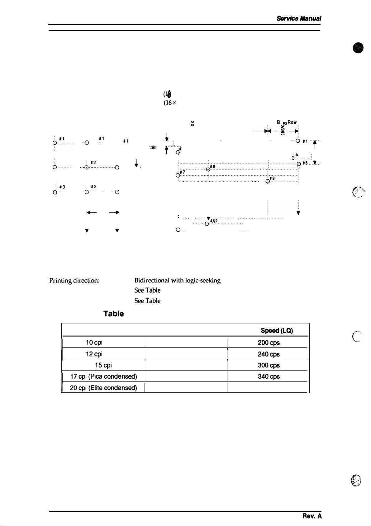
1.2.1 Printing Specifications
Msnual
Print system:
On demand inkjet system
Nozzle configuration: 64 nozzles
4$ nozzles
Yellow
i
#2
Q“-”--”-”””-
*#16
0
Cyan
’“0 ~’
-“”o”#-2-”””---e---e
“0:3 “““o
v
#16
o
Magenta
..() #l . .
64/360”
V
0
#16
t
1/90”
#2
4
. . . . . . . .
#3
.
,,36(J*
-- .-..
Figure 1-2. Nozzle Configuration
($
x
4 staggered): Monochrome
(16x
3
staggered): Color
Row D
+g-
. . . . . . . . . . . . . . . . . . . . . . . . . . . .
.$
--;..
----------------& 2-------------- .................. +...... -------------
:il
3
. . . . . . . . . . . . . . . . . . . . . . . . . . . . . . . . . . . . . . . . . . . . . . . . . . . . . . . . . . . . . . . . . . . . . . . . . . . .
tQ
i---------. ---"" ----i--" ----.. --"-. ----" ----------------6
:--.------;--------------
J87----::---""---------------"----------------.--.--!#8--------.-.----i
. . . . . . . . . . . . . . . . . . . . . . . . . . . . . . . . . . . . . . . . . . . . . . . . . . . . . . . . . . .
: ----- .
‘#63”
o -
Row C
:
.
-6;6
““””’viii”””-”””-
‘- -“0---=’------”” -
‘“ ’ --------- ‘- - --0864-- - --
721360”
.
. . . . . . . . . . . . . . . . . . . . . . . . . .
-------
“-”’”--”’-”
-------+ --------”
Row 8
-.4
.
. . .
__-+___..~#5
--”:--- --- -:
Q-.-......-:
“--””;-”””””-”
~
f?ow
A
s
0
.
.
--6 *I ‘- ““”
-;4--------------;
-.....0861
t
. :
1/90’
I
..*_.
Printingdirection: Bidirectionalwithlogic-seeking
Printspeed:
Printable columns:
SeeTable
SeeTable
l-2.
l-2.
TabIe l-2. Print Speed and Printable Columns
CharacterPitch
IOcpi
I
I
(Pica)
12cpi (Elite)
15cpi
17cpi (Picacondensed)
L
20cpi(Eiitecondensed)
I
PrintableColumns
I
I I
1
60
96
120
137
160
Print
I
1
Speed(LQ)
2oocps
240cps
3oocps
340cps
4oocps
1-2
Rev.A
Sty/us Co/or Service Manual
Product Description
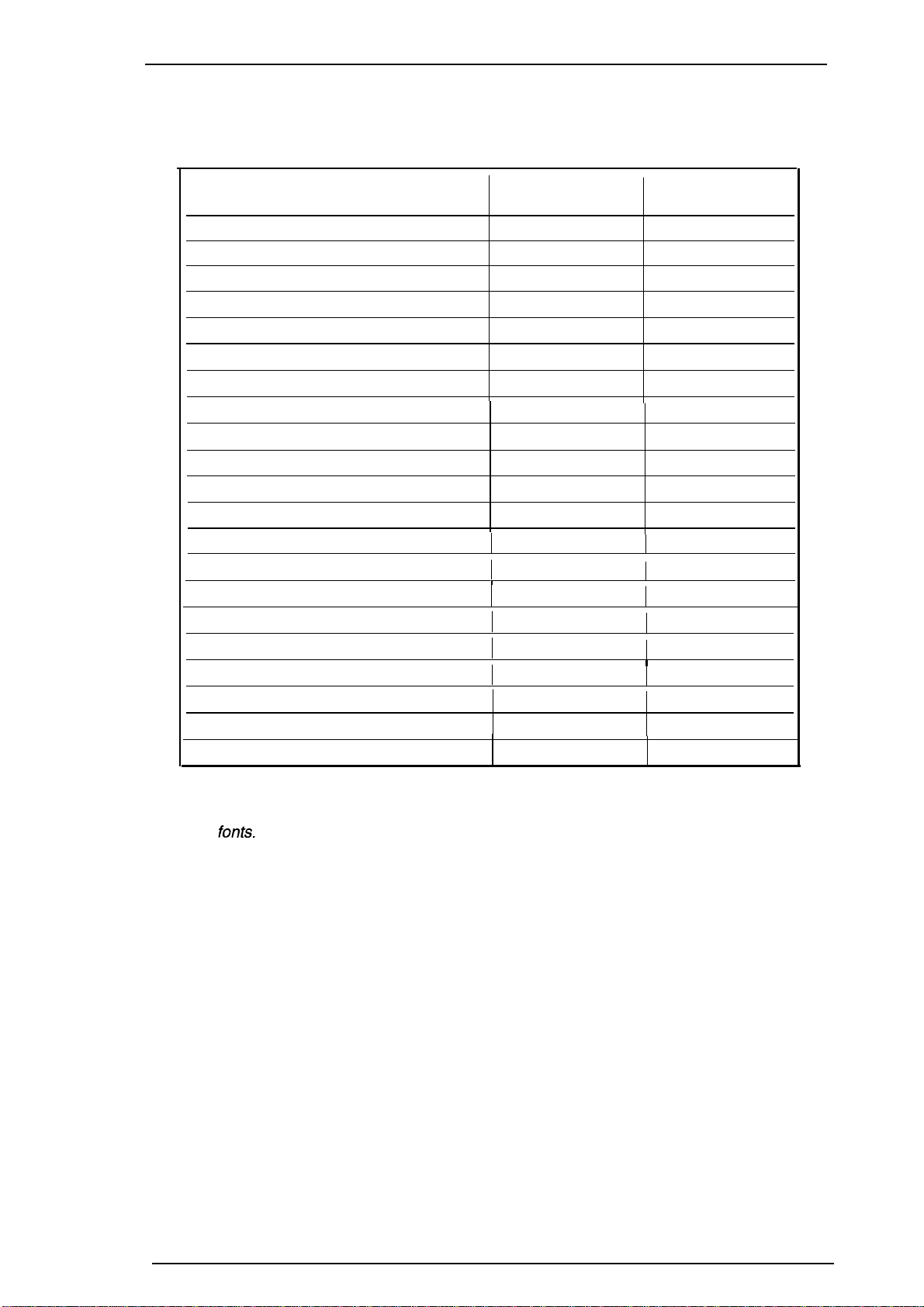
Character sets:
Character tables:
Character Tables
Italic
PC437 (U.S./Standard
PC850 (Multilingual)
PC860 (Portuguese)
PC861 (Iceland)
PC863 (Canadian-French)
PC865 (Nordic)
PC437 (Greek)
PC852 (East Europe)
PC853 (Turkish)
PC855 (Cyrillic)
PC857 (Turkish)
PC866 (Russian)
PC869 (Greek)
MAZOWIA (Poland)
Code MJK (Czechoslovakia)
ISO 8859-7 (Greek)
ISO Latin IT (Turkish)
Bulgaria (Bulgaria)
Abicomp
BRASCII
Legal and 14 international character sets.
See Table 1-3.
Table 1-3. Character Tables
Standard
Version
o 0
Europe)
0 o
o
o
o
o
o
x
x
x
x
x
I
1
x
x
x O
I
I
x
x
x
x
o
o
NLSP* Version
0
x
O
(Note)
O (Note)
O
(Note)
O
(Note)
O
(Note)
O
I
1
(Note)
O (Note)
(Note)
O
I
I
I
(Note)
O
(Note)
O
(Note)
O (Note)
x
x
x
x
x
o supported
Note:
These fonts are not supported for EPSON Roman Tand EPSON Saris Serif H of scalable
Fonts:
Control code:
Input data buffer:
X Not SUpported
Bitmap LQ fonts
-
EPSON Roman
- EPSON Saris Serif
- EPSON Courier
- EPSON Prestige
- EPSON Script
National Language Support Printer
*
(10 cpi/12 cpi/15 cpi/Proportional)
(10/12/15/Proportional)
(10/12/15)
(10/12/15)
(10/12/15)
Scalable fonts
-
EPSON Roman
- EPSON Saris Serif
- EPSON Roman T
10.5 points, 8
10.5 points, 8
-32
points (in
units of 2 points)
-32 points (in units of 2 points)
10.5 points, 8-32 points (in units of 2 points)
- EPSON Saris Serif H 10.5 points, 8-32 points (in units of 2 points)
ESC/P 2 and expanded raster graphics code
64K bytes
Rev.
A
1-3

Ptvduct
Rev. A
1.2.2
&SCf@th
Paper Handling Specifications
!wJdus
color
Sefvkw
Mmu8/
Feeding method:
Notes: The
following
1. Reverse feeding within 3 mm (O. 12in.) from the top edge of the paper or 16mm
(0.63 in.) from the bottom edge of the paper.
2. Reverse feeding beyond 7.9mm (0.3in.).
Line spacing:
Paper path:
Feeding speed:
1.2.3
Paper Specifications
Size (W x
L)
Thickness
Weight
Qualitv
Friction feed paper is fed from the built-in auto sheet feeder (ASF).
operations are
not allowed.
1/6 inch feed, 1/8 inch feed, or programmable with a 1/360 inch minimum
increment.
Cut sheet: Built-in auto sheet feeder (ASF) (front entry)
89 msec. (at l/6-inch feed pitch)
Table 1-4. Cut Sheet Paper Specifications
A4:
Letter:
B5:
I
Legal:
I
0.08 mm (0.003
55 g/m2 (17
Bond paper. PPC
210 mm
216 mm
(8.3
(8.5
in.)
in.) x
x 297
279
182 mm (7.2 in.) x 257
216
mm
(8.5
in.) x
356
in.) -0.11 mm (0.004 in.)
lb) -90 g/m2 (24
lb)
mm (1 1.7 in.)
mm (1 1.0 in.)
mm (10.1 in.)
mm (14.0 in.)
Size (W x
Thickness
Weight
Qualitv
Note:
Table 1-5. Envelope Specifications
I
I
No. 6:
L)
No. 10:
I
DL: 220 mm
]
Less than
75 g/m2 (20 lb) -90 g/m2 (24 lb)
Bond Paper
Envelope printing is supported onfy at room temperature.
When inserting envelopes, keep the longer side honzontal.
166
mm(6½ in.) x 92
mm (3 % in.)
240 mm(91A in.) x 104mm(41A in.)
(8.7
in.) x 110 mm (4.3 in.)
0.52
mm
(0.020
in.)
1-4
Stylus Color Service Manual
Product Description
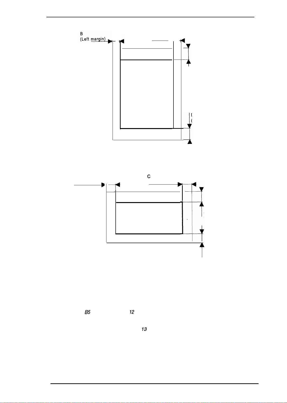
Printable area:
Cut sheet
c
(Right margin~
A
(Top margin)
Printable area
D
(Bottom margin)
i
Figure 1-3. Printable Area for Cut Sheet
Note:
Envelope
B
(Left margin)
A: The minimum top margin= 3 mm (0. 12 in.)
B: The minimum left margin= 3 mm (O. ?2 in.)
C: The minimum right margin is:
A4 size:
Letter size: 9 mm (0.35 in.)
i35
Legal size: 9mm (0.35 in.)
Envelope: 3 mm (0.12 in.)
D: The minimum bottom margin= 13 mm (0.51 in.)
B
-P
Figure 1-4. Printable Area for
3 mm (O. 12 in.)
size:
3 mm (0. 12 in.)
c
(Right margin)
Printable area
B
A
(Top
&
D
(Bottom margin)
Envelope
margin)
Rev. A
1-5
Product
Rev. A
Descfhtion
Stylus Color
Service
Ahnual
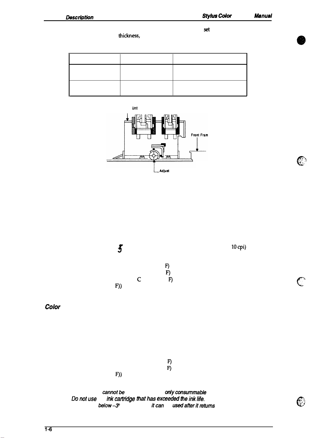
Adjust lever setting:
The adjust lever on the carriage unit must be
the paper
Lever Position
LEFT
(Vertical)
RIGHT
(Horizontal)
set
thiclmess,
as shown m Table 1-6.
Table 1-6. Adjust Lever Setting
Paper Thickness
0.08-0.11 mm
(0.003 -0.004 in.)
Less than 0.5 mm (0.020 in.)
Carriage
I
Paper
Cut Sheet
Envelope
Umt
~ Adjual
Lever
to the proper position for
e
Figure 1-5. Adjust Lever
1.2.4 Ink Cartridge Specifications
Black
Type:
Color:
Print capacity:
Life:
Storage temperature:
Dimension (W x D x H):
color
Type:
Color:
Exclusive cartridge
Black
1 million characters (315 dots/character, Roman
3
The effective life from the indicated production date is 2 years.
-30- 40° C (–22 - 104° F) (Storage, within a month at 40° C (104° F))
-30- 60° C (-22 –30 - 60° C (–22 -
F))
26.9 x67.4 X 41.8 mm (1.06 x2.65 X 1.65 in.)
Exclusive cartridge
Cyan, Magenta, Yellow
IOcpi)
140° F) (Transit, within a month at 40° C (104° F))
140” F) (Transit, within 120 hours at 60° C (140°
-%
c
Print capacity:
Life:
Storage Temperature:
Dimension (W x D x H):
Notes:- Ink cartridge
cannotbe
- Donotuse an inkcarlndge thathas exceededtheink/ife.
-
Ink freezes
below-~
1-6
28 sheets/color (A4, Full image printing at 360 dpi)
The effective life from the indicated production date is 2 years.
-30- 40° C (–22 - 104° F) (Storage, within a month at 40° C (104° F))
-30- 60° C (–22 - 140°
–30 - 60° C (–22 - 140”
F)
(Transit, within a month at 40° C (104° F))
F)
(Transit, within 120 hours at 60° C (140°
F))
54.0 X 67.4X
re-tiled; it is the
41.8 mm (2.13
onlywnsummable
X
2.65X
1.65 in.)
article.
C; however, itcan be usedafieritmfums to room temperature.
Stylus Color Service Manual
1.2.5 Electrical Specifications
Table 1-7. Rated Electrical Ranges
Product Description
Item
I
Rated voltage
Input voltage range
Rated frequency range
Input frequency range
Rated current
I
Power consumption
Insulation resistance
(self-test with
(applying 500
120 V Version
120
103.5-132 V
50-60 Hz
49.5 -60.5 Hz
0.6 A
Approx.
10-cpi LQ
10
Mf2,
minimum 10
VDC
and chassis)
1000
VAC rms
1200
Dielectric strength
VAC rms
(between AC line and chassis)
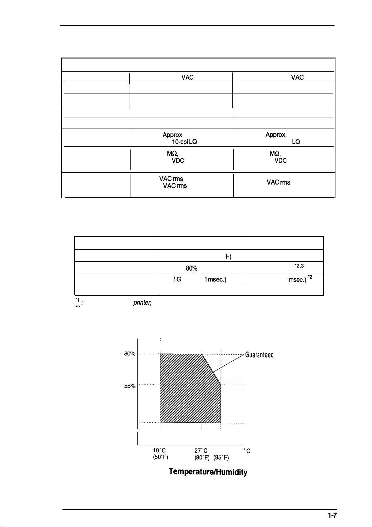
1.2.6 Environmental Conditions
Table 1-8. Acceptable Environmental Conditions
Description
VAC
20 W
characters)
between AC line
-1 minute or
-1 second
Operating
I
220-240 V Version
220-240
VAC
198-264 V
50-60 Hz
49.5 -60.5 Hz
I
0.4 A
Approx.
20 w
(self-test with 10-cpi LQ characters)
MQ,
minimum
(applying 500
VDC
between AC line
and chassis)
1500
VAC rms
-1 minute
(between AC line and chassis)
Non Operating
Temperature
Humidity
Shock resistance
Vibration resistance
:1:
For operating the
2
,
: These conditions are acceptable when the printer is in its shipping container.
3
: Without condensation.
Humidity
(% RH)
pn”nter,
80!!0
55?40
20?40
I
. . . . . . . . . . .
. . . . . . . . . . .
. . . . . . . . . . .
10-
35° c (50 - 95° F) “
20-
80!%0
RH ● ’73
IG (within 1
rnsec.)
0.15 G
–20 - 60° C (-4 - 122° F) ● 2
5- 85% RH
2G (within 2
0.50 G
“2’3
msec.)
2
conditions must be in the range shown in the figure below.
:
Guara,nleed
range
Rev. A
Io”c
(50”F)
Figure 1-6.
27°C
35°C
(80°F) (95°F)
Temperature/l=lumidity
‘c
(“F)
Range
1-7
Product
Llsscriptkm
1.2.7 Reliability
MTBF:
Total print volume:
Printhead life:
1.2.8 Safety Approvals
4JIO0
power on hour
75,0(X) pages
1$00 million
(pOH)
(A4,
Letter)
dots/nozzIe
stylus Colar
&wvke Msnusl
Safety
Radio frequency interference
standanis:
(RFI):
1.2.9 Physical Specifications
Dimension (W x D x H):
Weight
120V
version:
22@240V
120V
version:
220-240V
470
X
525X
7.4 Kg
(163 lb)
UL1950
CSA22.2
version:
version:
192 (mm) (18.5X 20.7X 7.56 (in.))
EN 60950
NEMKO,
FCC part 15 subpart B class B
Vfg.243 (VDE0878
EN55022
with D3,
#950 with D3
~, SEMKO, DEMKO,
SETI)
(CEPR
part 3, part 30)
PUB. 22) class B
.-
\
(
1-8
Rev. A

Stylus
Color
Service Manual
Product Description
1.3 INTERFACE SPECIFICATIONS
The Stylus Color is standard-equipped with an 8-bit parallel and serial interface.
1.3.1 Serial interface Specifications
Data format:
Synchronization:
Handshaking:
Signal level:
8-bit parallel
By STROBE pulse synchronization
By BUSY and
TTL compatible
ACKNLG
level
signals
Adaptable connector:
Data transmission timing:
BUSY
ACKNLG
DATA
STROBE
Figure 1-7. Data Transmission Timing
36 pin 57-30360
See Figure 1-7.
L.&
(Amphenol)
L_-
or equivalent
0.5 ps (minimum)
0.5
IJS
(minimum)
0.5
ps
(minimum)
Note:
The Busy signal is active (HIGH) under the following conditions:
The ERROR signal is active (LOW) under the following conditions:
The PE signal is active (HIGH) under the following conditions:
Transition time (rise time and fall time) of every input signal must be less than 0.2
- During data reception (See Figure 1-7.)
- When the input buffer is full
- When the INIT input signal is active
- During initialization
- When the ERROR or PE signal is active
- During the self-test mode
- During the demonstration mode
- During the default setting mode
- When a fatal error occurs
- When a paper-out error occurs
- When a no ink cartridge error occurs
- When a fatal error occurs
- When a paper-out error occurs
- When a fatal error occurs
ps.
Rev. A
1-9

Table 1-9 shows the
Rev. A
co
nm@or
pin assignments and signal functions
of the
8-bit parallel interface.
Table 1-9. Signal and Connector Pin Assignments
Pin No.
1
2-9 DATA 1-8
10
11
12
13
Signal Name
STROBE
ACKNLG
BUSY
PE
SLCT
I/o’
The
STROBE pulse is used to read data from the host
computer. The pulse
I
it is
HIGH, and data is latched with the rising edge of this
signal.
DATA 1-8 are parallel data
HIGH, the data bit is 1; when LOW, the data bit is O. The most
significant bit
I
maintained
active edge.
ACKNLG
approximately 10 p.s. This signal goes LOW upon the
o
completion of data reception to indicate that the printer
ready to receive further
The BUSY signal informs the host computer of the printer’s
status. When this signal is HIGH, the printer cannot accept
o
any more data.
This signal indicates whether paper is available in the printer
o
or not. A HIGH level indicates no paper.
o
Pulled up to
(MSB)
for 0.5 ps on either side of the STROBE signal’s
is an acknowledge pulse with a width of
+5V
through a 1.0 KQ resistor in the printer.
Description
width must be 0.5 ~ or more.
bits. When one of these signals
is
DATA 8. The signal state must
data.
for
Parallel Interface
Normally,
is
be
is
14
31
32
35
17
16
19-30
33,36
15,18,34
—
*
7he //0
If this signal is set to LOW, the printer automatically performs
AFXT
m
ERROR
+5V
CHASSIS
GND
-
-
-
column indicates the direction of the
one line feed upon receipt of a CR (carriage return) code. The
I
status of this signal is checked onty at power on and
initialization.
If this signal goes LOW, the printer is initialized. The pulse
I
width of this signal must be 50
This signal goes LOW if the printer has a fatal error or runs
o
out of paper.
Pulled up to
-
Chassis ground.
-
Signal ground.
.
.
.
Not
USed.
-
+5V
signal
@ or more.
through 1.0 KQ resistor in the printer.
as viewed hm the
printe~
. .
,.
c
2
1-1o

Stvlus Color
Service
Manual
1.3.2 Parallel Interface Specifications
RS-422
Data format:
serial
Product Description
Synchronization:
Handshaking:
Table 1-10.
State
Busy
Ready
Word length
Start bit:
Data bit: 8 bit
Parity bit:
Stop bit:
Bit rate:
Adaptable connector:
Recommended I/F cable:
Asynchronous
By
DTR
signal and X-ON/X-OFF protocol
DTR
and
X-OIVX-OFF
Buffer Space
Less than 512 bytes
More than 1,024 bytes
1 bit
none
1 bit
57.6K bps
8-pin mini-circular connector
Apple@
System Peripheral-8 cable
Protocol
DTR
off
On
X-OWX-OFF
X-OFF
X-ON
Table 1-11. Signal and Connector Pin Assignments for Serial Interface
Pin No.
Signal Name
I/o’
Description
1
2 NC
3
4 SG
5
6
7
8
* The
1/0 column
DTR
TXD
RXD
TXD
NC
RXD
indicates the data flow as viewed from the
out
out
In
In
out
In
Data terminal ready
No connection
Transmit data
Signal ground
Receive data
Balanced transmit
No connection
Balanced receive
printer.
Rev. A
1-11
Product
Rev. A
LMscriptkw
1.4 OPERATIONS
This
section describes the basic operations of the printer.
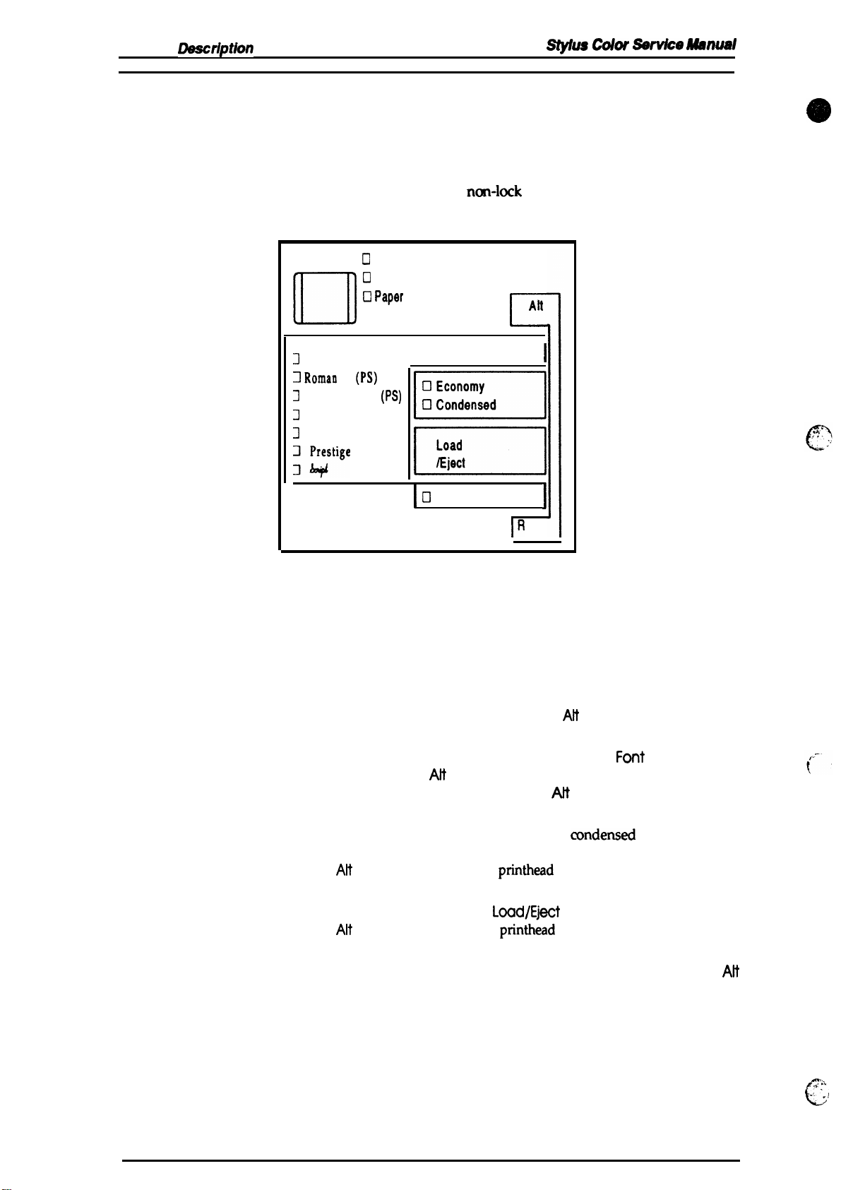
1.4.1 Control Panel
stylus COW
SerVke
Aww4d
The control panel for this printer has 1 lock type, 5
indicators for easy
operation
Un
J
3 Romau
3
Z
3
;$s’ige
of the various printer functions.
Cl
Operate
U
Data
O Pap9r
Out
No Ink Cartridge
Courier
T
(PS)
Saris Serif H
Roman
Saris Serif
Font
(PS)
m
m
Cl
ncm-lock
Pause
Figure 1-8. Control Panel Appearance
type push buttons, and 14 LED
Alt
c
I
I
IR
t
ese
Buttons
Operate
Att
Font
Economy/Condensed
Load/Eject
Pause Stops printing temporarily or resumes printing if it has been
Turns the printer on or off.
Modifies the function of other buttons. Holding down this button
for 3 seconds causes the printer to move the carriage to the ink
cartridge installation position. Pressing
to return to the home position.
Cycles through the font choices. pressing the
holding down the AH button causes the carriage to move to the gap
adjustment position. Pressing the AN button again causes the
carriage to return to the home position.
Selects either the economy printing or
Pressing the
the
Alt
button starts the color
Either loads a new sheet into the printer or ejects paper currently in
the paper path. Pressing the
the
Alt
button starts the black
stopped temporarily. Pressing
button resets the printer.
Economy/Condensed
printhead
L~d/E@t
printhead
Pause
Ait
again causes the carriage
F~t
button, while
mndensed
button while holding down
cleaning cycle.
button while holding down
cleaning cycle.
while holding down the
printing mode.
Alt
1-12
ma,.
L
~.
A
‘,
.;
Stvlus Color
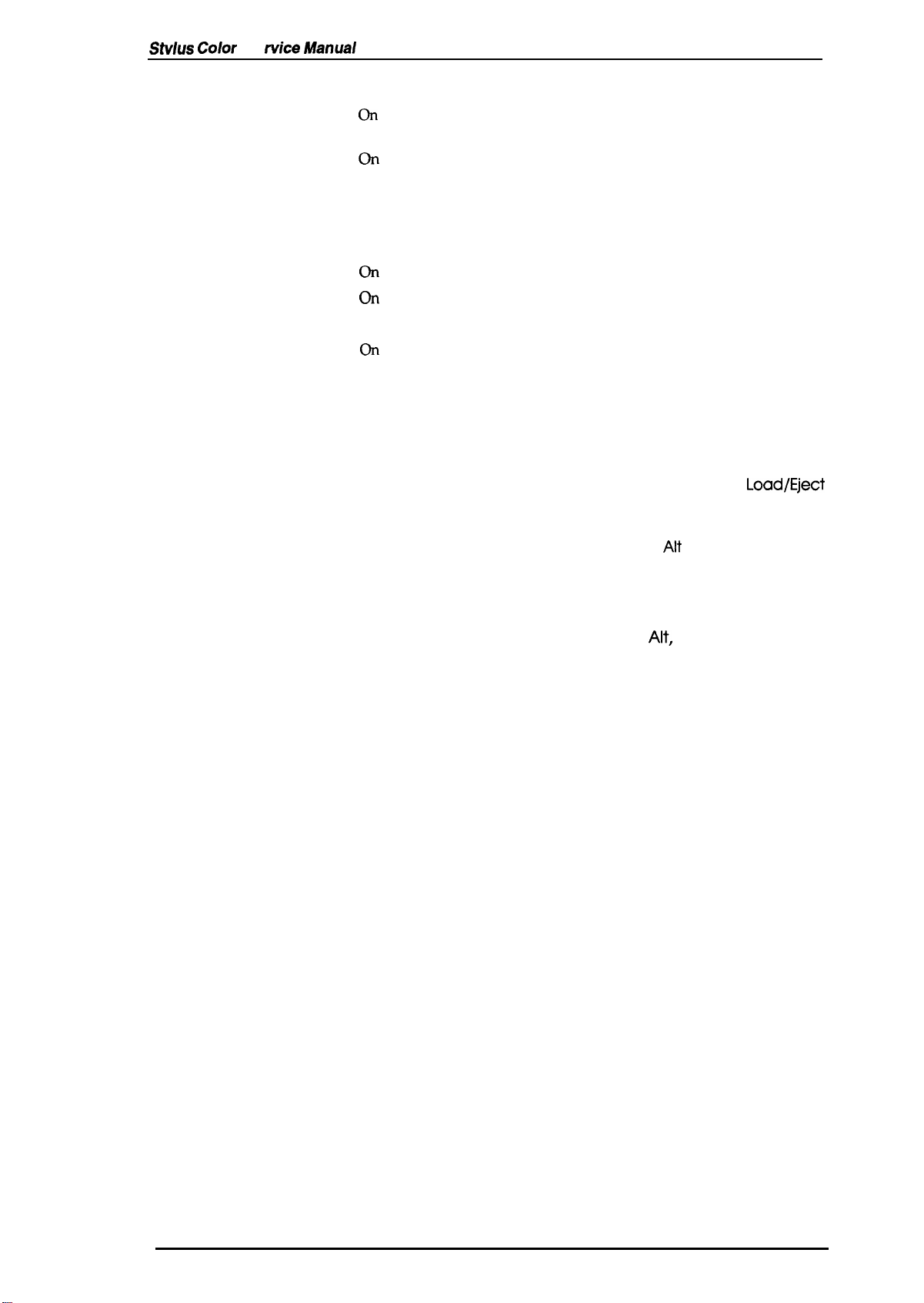
Indicators
Operate
Se
fvice Manual
Product Description
On
when the printer is on. Blinks during power on and off sequence.
Data
On when print data is in the input buffer. Data and Pause lights
blink if an error occurs.
On
Paper Out
when the printer is out of paper. Blinks when a paper jam
occurs.
On
No Ink Cartridge
Economy
Condensed
Font
Pause
when the ink is exhausted.
On
when economy printing mode is selected.
On
when condensed printing mode is selected.
These
LEDs indicate the selected font.
On
when printing is paused.
1.4.2 Panel Operation at Power On
You can activate the following modes by doing the following:
Self-test mode
Hex dump mode
Demonstration mode
Default setting mode
Initialize EEPROM
Turn on the printer while holding down the
Turn on the printer while holding down the
buttons. Once this mode is selected, the printer prints all received
data in hexadecimal format.
Turn on the printer while holding down the
Turn on the printer while holding down the Economy/
Condensed
button. For more information about the mode, see
Section 1.4.3.
Turn on the printer while holding the Alt, Font, Load/Eject, and
Pause
buttons.
Load/Eject
Font
and
Alt
button.
button.
Load/Eject
Rev. A
1-13
Product
Oesct’iptkm
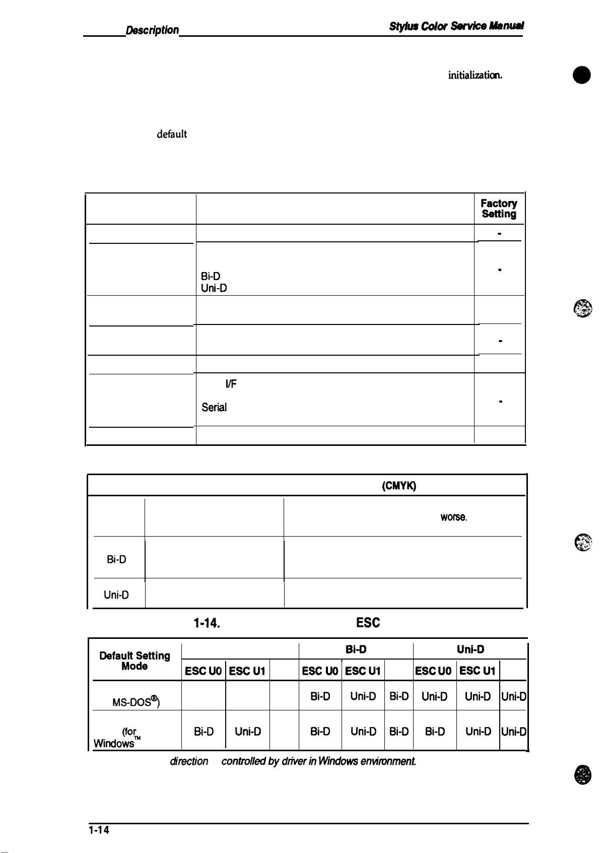
1.4.3 Default Settings
St’jms Cokw
SawicO
ManUd
The printer can save some printer setting parameters that define its functions at
can change these parameters by using the printer’s default setting mode.
initializatkn.
1.4.3.1 Default Setting Items
You can
default-setting mode by holding down the
printer.
use the
det%ult
setting mode to change the settings listed in the table below. Activate the
Economy/Condensed
button while turning on the
Table 1-12. Default Setting Items
Menu
Contents
Character table
Print direction
Network l/F mode
Auto line feed
Loading position
Selects the character table
Controls the print direction. (See Tables 1-12 and 1-13)
Auto
Bi-D
Uni-D
Off: For normal environments.
On: For network environments.
On: Valid
Off: Invalid
3.0/8.5
mm (0.12/0.33 in.)
Description
You
mct31111
.
.
off
.
3.0
mm
e
Interface mode
Auto l/F wait mode
Table 1-13. Characteristics of Print Direction Mode
ttem
Auto
Bi-D
Uni-D
Black and White Printing
I
Throughput and quality is
better.
Throughput is best.
Print quality may be down.
Throughput is worse.
Print quality is better.
Table
l)efaul:~~tting
Auto
I/F
mode
Parallel l/F mode
Seriil
l/F mode
Optional l/F mode
1 0/30 seconds
1-14.
Printing Direction and
Auto
ESC UO
ESC U1
.
10 sec.
Color
I
Throughput is better.
Color quality with special paper is
(Color correction depends on the printing direction.)
Throughput is better.
Color quality with special paper is worse.
(Color correction depends on the printing direction.)
Throughput is worse.
Color quality is best.
Bi-O
r
None
ESC UO
ESC UI
(CMYK)
ESC
U Command
Printing
WOW.
None ESC UO
Uni-D
ESC U1
None
Character mode
(for
MS-DOS?
Raster graphics
mode (fo~
Vvindows
Note:
1-14
)
Printing
Auto
Bi-D
ditection
Auto
Uni-D
is
controlkdby
Auto
Auto
dtiverin
Bi-D
Bi-D
IMndows entimnment
Uni-D
Uni-D
Bi-D
Bi-D
Uni-D Uni-D Uni-D
Bi-D Uni-D
Uni-D
Rev.
*
A

Stylus Color Service Manual
Product Description
1.4.3.2 Changing the Default Settings
To change the printer’s default settings:
a.
Hold down the
sheet that shows the firmware version and describes how to select the language used to print
messages.
b.
Press
the
Font
which language corresponds to which font LED.
Economy/Condensed
button until the appropriate font LED is selected. The following table shows
button and turn on the printer. The printer pMts a
Table 1-15. Language Selection
Language
English
Fran~is
Deutsch
Italiana Roman
Espafiol
c.
Press the
prints a table showing how to change the printer settings.
d.
Press
the
indicated by the Courier, Roman T
Font button, you adance to the next setting, and the three font
selection.
Alt
button. The printer prints the current settings using the selected language. It also
Font
button to advance through the setting menu. The current printer settings are
(PS)~and
Font LED
Courier
Roman T
Saris Serif H
Saris Serif
San Se;if H
(PS)
(PS)
Table 1-16. Feature Selection
Menu
Saris
Serif H
(ps)
LED
Setting
Feature/Menu
Courier
LED
Roman T
(PS)
LED
(PS) LEDs. Ead”time
LEDs
change according to the
Setting Value
I
O rate
r
ED
I i
Data Paper
LED
you
pr&s
the
Out LED
Character table
Print direction
Vetwork
Loading position
Auto l/F
e. Change the setting value by pressing
l/F mode
Auto line feed
interface mode
wait time
for the current menu. The status
On
On
off
On
off
On
off
On
off
On
On
off
off
On
Alt
of the
On
I
I
off
I
off
off
On
I
On
I
On
button. Pressing the
LEDs
I
Auto
I
Bi-D
Uni-D
off
On
off
On
3
mm
8.5 mm
Auto
Parallel
Serial
Option
I
10
sec.
30 sec.
will be changed as the button is pressed,
See Table 1-16
On
I
off
I
On
off
On
off
On
off
On
On
off
On On
I
Off
off
On
Alt
button changes the setting
off off
1
On
I
On
off
off
off
off off
off
off
off
On
off
1
off
off
+
I
r
off
1
off
off
off
off
off
off
off
off
off
On
1
off
off
-
Rev. A
1-15

Pfvduct
Rev.
Description
Sty#Us Cokw
Table 1-17. Character Table Selection
~
Mllnuul
Version
Common
Standard
NLSP
f. Repeat d and e to change other printer settings. The setting menu selection will return to the
first menu after the
g. Turn off the printer. The setting is stored intonon-volatile memory.
Settings
Italic U.S.A.
Italic France
Italic Germany
Italic U.K.
ttalic
Denmark 1
Italic Sweden
Italic Italy
Italic Spain 1
PC437
PC850
PC860
PC863
PC865
PC861
BRASCII Blinks
Abicomp
PC437
Greek
PC853 Blinks
PC855
PC852 On
PC857 Blinks
PC866
PC869
MAZOWIA
Code MJK
1s0
8859-7
ISO Latin IT
Bulgaria
lastmenu *l@ion
Operate LED
off off
On
Blinks
Off On
On On
Blinks
off
On
Blinks Blinks
off off
On
Blinks
off
On
off
off
off
off
On
Blinks
off
On
Blinks
off
is over.
Data LED
m
off off
On
Blinks
Blinks
off
off on
On
On
On
Blinks
off
Off
On
On
On
Blinks
Blinks
Blinks
off
off
off
On
Pa~hr)ut
Off
off
off
off
Off
Off
oft
Off
on
On
on
On
On
On
On
on
on
on
on
On
on
On
Blinks
Blinks
Blinks
Blinks
,
:-l.
.
t
,’
“
c.
. .
;
c
G.-
1-16
A
Sty/us Color Service
Manual
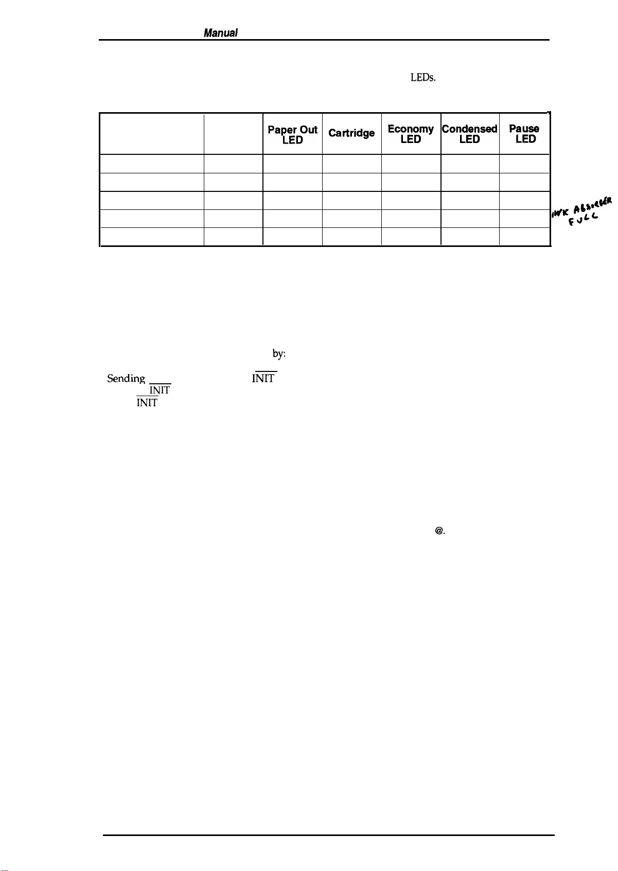
1.4.4 Error Conditions
Product Description
The printer can detect the various errors and indicate them with the
LEDs.
Table 1-18. Error Indications
f
Error
Paper out
No ink cartridge
Paper jam
Maintenance request
Carriage error
Data LED
off
off off
off
Blinks
Blinks
Pa~;rDOut
On
Blinks
Blinks
off off
No Ink
Catiridge
LED
off
On
off
Blinks Blinks
Ecm~my
off off
off off
off
off off
Con&sed
off off
Blinks
Pfg~
off
off
Blinks
Blinks
#KG@$4 L
1.4.5 Printer Initialization
There are three initialization methods: hardware initialization, software initialization, and panel
initialization.
1.4.5.1 Hardware
Hardware initialization is performed
Turning on the printer.
-
%mdin~
the parallel interface
(If the
INIT
the
INIT
signal becomes inactive.)
Initialization
by:
INIT
signal.
signal is active when the printer is turned on, hardware initialization is started when
,,4#R
When the hardware initialization is performed:
- The printer mechanism is initialized.
Input data buffer is cleared.
Downloaded character definitions are cleared.
Print buffer is cleared.
Default values are set.
1.4.5.2 Software Initialization
Software initialization is performed upon receipt of the control code ESC
When the software initialization is performed:
Print buffer is cleared.
Default values are set.
1.4.5.3 Panel Initialization
This printer is initialized by pressing the
When the panel initialization is performed:
Input data buffer is cleared.
Print buffer is cleared.
Default values are set.
Load/Eject
button while pressing the
@.
Alt
button.
Rev. A
1-17

Product
Rev. A
—
Descriptkm
1.5 MAIN COMPONENTS
- . — . - . --
-
Color Setvke
hfg@g##
.
The main components of the Stylus Color
Q
Printer mechanism
Q
Main control board
Cl
Power supply unit(C137PSB/PSE Board)
Q
Control panel board
Q
Housing
1.5.1 Main Control Board
The Main Control Board
array, a program ROM
and a lithium battery for powering the
equipped with both a logic system and a power system.
NJ.5P
(National Language Support Printer) specification.
z~
,
(M-4A10)
(C137
MAIN Board)
(C137PNL
(C137
(C137
MAIN Board) consists of an
(4M),
a dynamic
. . . . . . . . .
CN2
are:
Board)
MAIN Board)
RAM (4M),
protect counters.
IC14
a mask ROM
SLA7041
H8/3003
The
reset IC
The
8M program ROM is used only
1
1
m
l~bit CPU, E05A% gate
(4M
or
8M),
an
EEP-ROM
(M51955
~ ICl!i SI A7041
.-
,“ — .,
I
f-l
and ~ 592) is
“
—
c)
z
0
-
RM12
(lK),
fix
the
#——————
Figure 1-9.
/
Q14
CN1
K
BAT 1
C137
MAIN Board Component Layout
RM11
\@
i
I
(
“
.,
1-18
Stylus Color Service Manual
Product Description
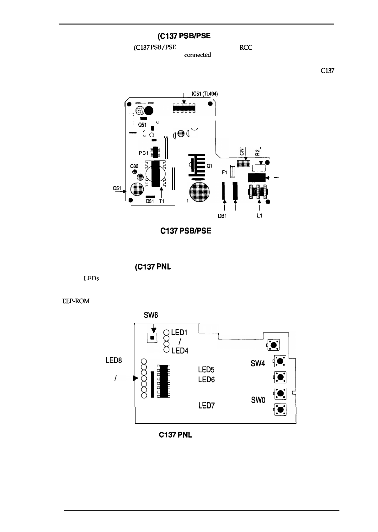
1.5.2 Power Supply Board
The
Power Supply Board
This board is equipped with a power switch
is turned off, it can continue to operate in order to eject the paper and perform the head capping
operation. The power on/off signal is always monitored by the E05A96 gate array on the
MAIN Board,
and the logic system
CN2 ,
(C137 PSB/PSE
:-
. .
; Q51
–Qo
c~
(C137 PSB/PSE
Board) consists of an
comected
recognizes the power switch status.
j-- IC51 (TL494)
n
Board)
RCC
switching regulator circuit.
to the secondary circuit. Thus, if the printer
I
J
(@r
aa
u
I
cl
1-
DB1
C3
1-
,
L1
C137
–
cl
—
Figure 1-10.
1.5.3 Control Panel
The 14
6 switches in combination with one another, the printer can operate in each protect operation (color
or black cleaning, cartridge exchanging self-test, default setting value exchanging, reset, and
EEP-ROM
LEDs
on this board indicate the error status (there is no buzzer system); by using the
clear operation).
LED8
/-
LED14
(C137 PNL
t
[It
C137 PSB/PSE
Board)
SW6
❑
q
LED1
LED4
Component Layout
t
1---1
/
LED5
0
LED6
0
I
m7
0
I
SW4 Ill
M
/
i-l
Swo
n
● 0
‘0
:0°
m
—
‘
I
Rev.
Figure 1-11.
A
C137 PNL
Board Component Layout
1-19
Product
Rev. A
D9sctiptk3n
Stylus
Color *vim Manual
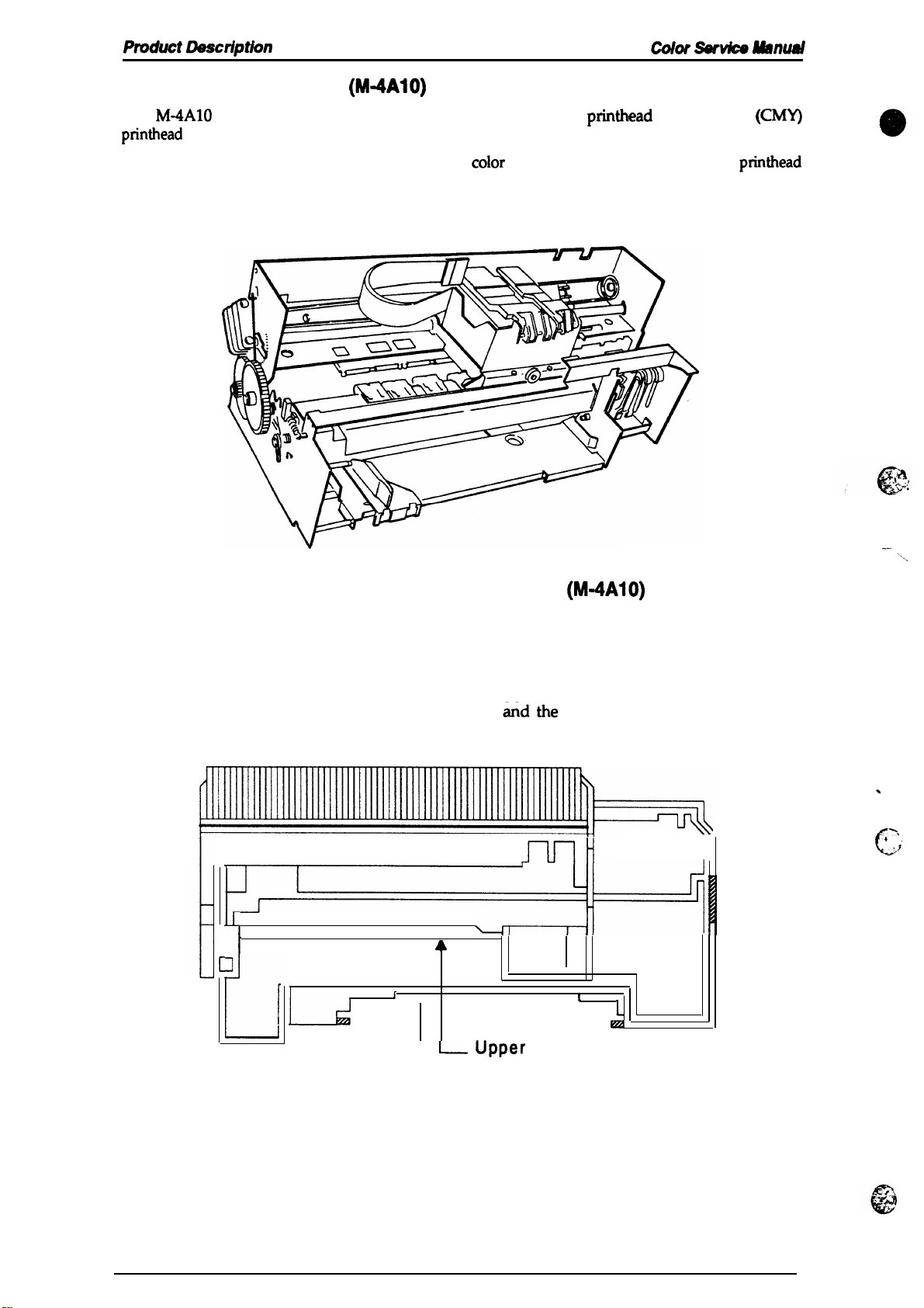
1.5.4 Printer Mechanism
The
M-4A1O
printhead
The ink system has both a black pump unit and a
is made to flow into the individual caps. Power for the pump system and paper feed system is
supplied from the paper feed motor.
printer mechanism is equipped with a 64-black
on the carnage unit. Resolution of 720 dpi is possible with special (non-absorbent) paper.
(M-4A1O)
printhead
coIor
pump unit. Waste ink from each
and M-color
(CMY)
printhead
Figure 1-12. Printer Mechanism
1.5.5 Housing
The Stylus Color housing consists of the printer cover, uppercase, and the lowercase.
Attached to the housing
separator.
1
I
are the front paper
r
A
L
support
4
L- upper
Lower Case
ejected paper support
mH
1
L
km
Case
with paper
II
-—
4
-.
c
‘.,
‘,
-7
1-20
Figure 1-13. Housing
Chapter 2 Operating Principles
Table of Contents
2.1 OVERVIEW
2.2
OPERATING PRINCIPLES OF THE PRINTER MECHANISM
2.2.1
2.2.2
Printer Mechanism. . . . . . . . . . . . . . . . . . . . . . . . . . . . . . . . . . . . . . . . . . 2-2
Carriage Drive Mechanism . . . . . . . . . . . . . . . . . . . . . . . . . . . . . . . . . . . 2-5
2.2.2.1 Platen GapAdjust Lever . . . . . . . . . . . . . . . . . . . . . . . . . . . . . . . 2-6
2.2.3
2.2.4
2.2.5
2.2.6
2.2.7
2.3
2.3.1 Operating Principles
2.3.2 Operating
Paper Feed Mechanism. . . . . . . . . . . . . . . . . . . . . . . . . . . . . . . . . . . . . . 2-6
InkSystem. . . . . . . . . . . . . . . . . . . . . . . . . . . . . . . . . . . . . . . . . . . . . . . . 2-8
Pump Mechanism . . . . . . . . . . . . . . . . . . . . . . . . . . . . . . . . . . . . . . . . . . 2-9
Cap Mechanism. . . . . . . . . . . . . . . . . . . . . . . . . . . . . . . . . . . . . . . . . . . 2-12
Wiping Mechanism
..~ . . . . . . . . . . . . . . . . . . . . . . . . . . . . . . . . . . . . . 2-12
OPERATING PRINCIPLES OF THE ELECTRICAL CIRCUITS
ofthe
Power Supply Circuit . . . . . . . . . . . . . . . . .
2.3.2.1
2.3.2.2
2.3.2.3
2.3.2.4
2.3.2.5
2.3.2.6
2.3.2.7
Principlesofthe
Reset Circuits.. . . . . . . . . . . . . . . . . . . . . . . . . . . . . . . . . . . . .
SensorCircuits. . . . . . . . . . . . . . . . . . . . . . . . . . . . . . . . . . . . .
Carriage MotorDriveCircuit . . . . . . . . . . . . . . . . . . . . . . . . . . .
Paper Feed Motor Drive Circuit. . . . . . . . . . . . . . . . . . . . . . . . .
Printhead
Drive Circuit . . . . . . . . . . . . . . . . . . . . . . . . . . . . . . .
DMAControlier. . . . . . . . . . . . . . . . . . . . . . . . . . . . . . . . . . . . .
D-RAM Refreshment Controller. . . . . . . . . . . . . . . . . . . . . . . . .
Main Control Circuit . . . . . . . . . . . . . . . . . .
2-1
2“1
2-13
2-13
2-15
2-16
2-16
2-17
2-19
2-20
2“21
2-22
2.4
INK SYSTEM MANAGEMENT
2.4.1
InkOperations. . . . . . . . . . . . . . .
2.4.1.1
2.4.1.2
2.4.1.3
2.4.1.4
2.4.1.5
2.4.1.6
2.4.1.7
2.4.1.8
2.4.1.9
2.4.1.10
2.1.4.11
2.4.1.12
2.4.1.13
2.4.1.14
2.4.1.15
2.4.1.16
2.4.1.17
2.4.1.18
PowerOnOperation. . . .
Cleaning Selection Mode
Micro Absorbing Cleaning
PowerOffOperation . . .
Print Start Operation . . .
Refresh Operation . . . . .
Standby Operation . . . . .
Fail Absorbing Operation
Ink Cartridge Replacement Operation . . . . . . . . . . . . . . . . . . . .
Wiping Operation 1 . . . . . . . . . . . . . . . . . . . . . . . . . . . . . . . . .
WipingOperation2 . . . . . . . . . . . . . . . . . . . . . . . . . . . . . . . .
Rubbing Operation . . . . . . . . . . . . . . . . . . . . . . . . . . . . . . . . .
Disengage ON Operation . . . . . . . . . . . . . . . . . . . . . . . . . . . .
Disengage OFFOperation . . . . . . . . . . . . . . . . . . . . . . . . . . .
Micro Absorbing Operation . . . . . . . . . . . . . . . . . . . . . . . . . . .
Carriage Lock Set. . . . . . . . . . . . . . . . . . . . . . . . . . . . . . . . . .
Carriage Lock Reset. . . . . . . . . . . . . . . . . . . . . . . . . . . . . . . .
Refresh Operation (Performed when loading or
ejecting paper) . . . . . . . . . . . . . . . . . . . . . . . . . . . . . . . . . . . .
Adjust Lever Operate Position Moving Sequence. . . . . . . . . .
2.4.2
2.4.1.19
TimerandCounter. . . . . . . . . . . . . . . . .
2.4.2.1 Refresh Timer (Monochrome and
2.4.2.2 Timer (Monochrome and
2.4.2.3 Flushing Counter (Black,
Rev. A
. . . . . . . . . . . . . . . . . . . . . . . . . . . .
. . . . . . . . . . . . . . . . . . . . . . . . . . . . .
. . . . . . . . . . . . . . . . . . . . . . . . . . . . .
Operation . . . . . . . . . . . . . . . . . . . .
. . . . . . . . . . . . . . . . . . . . . . . ,..,.,
. . . . . . . . . . . . . . . . . . . . . . . ,.,,..
. . . . . . . . . . . . . . . . . . . . . . . . . . . . .
. . . . . . . . . . . . . . . . . . . . . . . . . . . . .
. . . . . . . . . . . . . . . . . .m.,m, ,,..,.
....._...;..
CMY
CMY
Head). . . . . . .
CMY
Head). . . . . . .
Head)
. . . . . . . . . . . . .
. . . . . . . . . . . . .
. . . . . . . . . . . ,.
. . . . . . . . . . . . .
2-23
2-24
2-24
2-25
2-26
2-26
2-26
2-27
2-27
2-27
2-28
2-29
2-29
2-29
2-29
2-29
2-30
2-30
2-30
2-30
2-30
2-30
2-30
2-31
2-31
2-i

2.4.2.4 Fail Absorbing Timer (Black,
2.4.2.5
2.4.2.6
Ink Level Counter R (On the RAM)
CMY
(Monochrome = Rb,
= Ry) . . . . . . . . . . . . . . . . . . . . .. ..2-31
CL Counter K (Monochrome = Kb,
2.4.2.7 CL2 Counter KK (Monochrome = KKb,
2.4.2.8
Protect Counter. . . . . . . . . . . . . . . . . . . . . . . . . . . . . . . . . . . . . 2-32
CMy
Head) . . . . . . . . . . . . .....2-31
CMY
= Ky) . . . . . . . . . . . . . 2-32
CMY
= KKy). . . . . . . . . 2-32
@
List of Figures
Figure 2-1. Printer Mechanism Block . . . . . . . . . . . . . . . . . . . . . ...........2-1
Figure 2-2. Structure of
Figure 2-3. Principles of the Printing Operation. . . . . . . . . . . . . . . . . . . . . .. ..2-3
Figure 2-4. Microwave Mode Operation . . . . . . . . . . . . . . . . . . . . . ........2-4
Figure 2-5. Carriage Drive Mechanism . . . . . . . . . . . . . . . . . . . . . . . . . . . . . . . 2-5
Figure 2-6. Platen Gap Lever Operation. . . . . . . . . . . . . . . . . . . . . . . . . . . . . . 2-6
Figure 2-7. Paper Feed Mechanism . . . . . . . . . . . . . . . . . . . . . ............2-7
Figure 2-8. Ink System Block . . . . . . . . . . . . . . . . . . . . . .................2-8
Figure 2-9. Pump Mechanism Block. . . . . . . . . . . . . . . . . . . . . . ...........2-9
Figure 2-10. Switch Lever Set. . . . . . . . . . . . . . . . . . . . . . . . . . . . . . . . . . . . . . 2-9
Figure 2-11. Paper Feed Mechanism Block . . . . . . . . . . . . . . . . . . . . . . . . . . 2-IO ‘-=
Figure 2-12. Switch Lever Reset. . . . . . . . . . . . . . . . . . . . . . . . . . . . . . . . . . . 2-10
Figure 2-13. Pump Operation . . . . . . . . . . . . . . . . . . . . . . . . . . . . . . . . . . . . . 2-11
Figure 2-14. Cap Mechanism . . . . . . . . . . . . . . . . . . . . . . . . . . . . . . . . . . . . . 2-12
Figure 2-15. Wiping Mechanism . . . . . . . . . . . . . . . . . . . . . . . . . . . . . . . . . . . 2-12
Figure 2-16. Block Diagram of the Electrical Circuit . . . . . . . . . . . . . . . . . . . .
Figure 2-17. Power Supply Circuit Block Diagram. . . . . . . . . . . . . . . . . . . . . .
Figure 2-18. Main Control Circuit Block Diagram . . . . . . . . . . . . . . . . . . . . . . 2-15
Figure 2-19. Reset Circuit Block Diagram. . . . . . . . . . . . . . . . . . . . . . . . . . . . 2-16
Figure 2-20. Sensor Circuit Block Diagram. . . . . . . . . . . . . . . . . . . . . . . . . . . 2-16
Figure 2-21. Carriage Motor Circuit Block Diagram. . . . . . . . . . . . . . . . . . . . .
Figure 2-22. Serial Data Transfer Procedure. . . . . . . . . . . . . . . . . . . . . . . . . . 2-18
Figure 2-23. Paper Feed Motor Drive Circuit Diagram . . . . . . . . . . . . . . . . . . 2-19
Figure 2-24. Trapezoidal Drive Wave Form. . . . . . . . . . . . . . . . . . . . . . . . . . . 2-20
Figure 2-25.
Printhead
Figure 2-26. DMA Controller Operation. . . . . . . . . . . . . . . . . . . . . . . . . . . . . . 2-21
Figure 2-27. D-RAM Cycle Timings. . . . . . . . . . . . . . . . . . . . . . . . . . . . . . . . . 2-22
Figure 2-28. Junction Method (CPU-DRAM). . . . . . . . . . . . . . . . . . . . . .. ...2-22
Figure 2-29. Relation of Ink System & Carriage Operation. . . . . . . . . . . . . . . 2-23
Figure 2-30. Power On Operation Classification. . . . . . . . . . . . . . . . . . . . . . . 2-24
Figure 2-31. Power Off Operation Classification. . . . . . . . . . . . . . . . . . . . . . . 2-26
Figure 2-32. Ink Cartridge Replacement Classification . . . . . . . . . . . . . . . . . . 2-28
Printhead.
. . . . . . . . . . . . . . . . . . . . . .............2-2
2-13
2-14
2-17
Drive Circuit Block Diagram . . . . . . . . . . . . . . . . . . . . 2-20
f~l
f
k.
-.
~.-
List of Tables
Table 2-1. Carriage Drive Motor Specifications. . . . . . . . . . . . . . . . . . . . . .. ..2-5
2-2.
Table
Table
Table 2-4. Paper Feed Drive Motor Specification . . . . . . . . . . . . . . . . . . . . .. .2-6
Table 2-5. Drive Terms. . . . . . . . . . . . . . . . . . . . . . . . . . . . . . . . . . . . . . . . . .. 2-7
Table 2-6. Pump Mechanism Operation . . . . . . . . . . . . . . . . . . . . . . . . . . . . . 2-11
Table 2-7. DC Voltage Distribution . . . . . . . . . . . . . . . . . . . . . . . . . . . . . . . . . 2-13
Table 2-8. Serial Data contents . . . . . . . . . . . . . . . . . . . . . . . . . . . . . . .....2-17
Table 2-9. Paper
Table 2-10. Junction Method
2-ii
Drive Terms . . . . . . . . . . . . . . . . . . . . . . . . . . . . . . . . . . . . . . . . .. .2-5
2-3.
Platen Gap Adjust Lever Position. . . . . . . . . . . . . . . . . . . . . . . . . . . 2-6
Feed Motor Drive Modes. . . . . . . . . . . . . . . . . . . . . . .....2-19
(CPU-2CAS
DRAM) . . . . . . . . . . . . . . . . . . . . .2-22
Rev. A
C,?,
*U)
 Loading...